EP4099509B1 - Connector assembly - Google Patents
Connector assembly Download PDFInfo
- Publication number
- EP4099509B1 EP4099509B1 EP22172334.9A EP22172334A EP4099509B1 EP 4099509 B1 EP4099509 B1 EP 4099509B1 EP 22172334 A EP22172334 A EP 22172334A EP 4099509 B1 EP4099509 B1 EP 4099509B1
- Authority
- EP
- European Patent Office
- Prior art keywords
- connector
- mating
- terminal
- orientation
- horizontal direction
- Prior art date
- Legal status (The legal status is an assumption and is not a legal conclusion. Google has not performed a legal analysis and makes no representation as to the accuracy of the status listed.)
- Active
Links
Images


Classifications
-
- H—ELECTRICITY
- H01—ELECTRIC ELEMENTS
- H01R—ELECTRICALLY-CONDUCTIVE CONNECTIONS; STRUCTURAL ASSOCIATIONS OF A PLURALITY OF MUTUALLY-INSULATED ELECTRICAL CONNECTING ELEMENTS; COUPLING DEVICES; CURRENT COLLECTORS
- H01R13/00—Details of coupling devices of the kinds covered by groups H01R12/70 or H01R24/00 - H01R33/00
- H01R13/73—Means for mounting coupling parts to apparatus or structures, e.g. to a wall
-
- H—ELECTRICITY
- H01—ELECTRIC ELEMENTS
- H01R—ELECTRICALLY-CONDUCTIVE CONNECTIONS; STRUCTURAL ASSOCIATIONS OF A PLURALITY OF MUTUALLY-INSULATED ELECTRICAL CONNECTING ELEMENTS; COUPLING DEVICES; CURRENT COLLECTORS
- H01R13/00—Details of coupling devices of the kinds covered by groups H01R12/70 or H01R24/00 - H01R33/00
- H01R13/02—Contact members
- H01R13/20—Pins, blades, or sockets shaped, or provided with separate member, to retain co-operating parts together
-
- H—ELECTRICITY
- H01—ELECTRIC ELEMENTS
- H01R—ELECTRICALLY-CONDUCTIVE CONNECTIONS; STRUCTURAL ASSOCIATIONS OF A PLURALITY OF MUTUALLY-INSULATED ELECTRICAL CONNECTING ELEMENTS; COUPLING DEVICES; CURRENT COLLECTORS
- H01R13/00—Details of coupling devices of the kinds covered by groups H01R12/70 or H01R24/00 - H01R33/00
- H01R13/40—Securing contact members in or to a base or case; Insulating of contact members
-
- H—ELECTRICITY
- H01—ELECTRIC ELEMENTS
- H01R—ELECTRICALLY-CONDUCTIVE CONNECTIONS; STRUCTURAL ASSOCIATIONS OF A PLURALITY OF MUTUALLY-INSULATED ELECTRICAL CONNECTING ELEMENTS; COUPLING DEVICES; CURRENT COLLECTORS
- H01R12/00—Structural associations of a plurality of mutually-insulated electrical connecting elements, specially adapted for printed circuits, e.g. printed circuit boards [PCB], flat or ribbon cables, or like generally planar structures, e.g. terminal strips, terminal blocks; Coupling devices specially adapted for printed circuits, flat or ribbon cables, or like generally planar structures; Terminals specially adapted for contact with, or insertion into, printed circuits, flat or ribbon cables, or like generally planar structures
- H01R12/70—Coupling devices
- H01R12/71—Coupling devices for rigid printing circuits or like structures
- H01R12/712—Coupling devices for rigid printing circuits or like structures co-operating with the surface of the printed circuit or with a coupling device exclusively provided on the surface of the printed circuit
- H01R12/716—Coupling device provided on the PCB
-
- H—ELECTRICITY
- H01—ELECTRIC ELEMENTS
- H01R—ELECTRICALLY-CONDUCTIVE CONNECTIONS; STRUCTURAL ASSOCIATIONS OF A PLURALITY OF MUTUALLY-INSULATED ELECTRICAL CONNECTING ELEMENTS; COUPLING DEVICES; CURRENT COLLECTORS
- H01R13/00—Details of coupling devices of the kinds covered by groups H01R12/70 or H01R24/00 - H01R33/00
- H01R13/02—Contact members
- H01R13/22—Contacts for co-operating by abutting
- H01R13/24—Contacts for co-operating by abutting resilient; resiliently-mounted
-
- H—ELECTRICITY
- H01—ELECTRIC ELEMENTS
- H01R—ELECTRICALLY-CONDUCTIVE CONNECTIONS; STRUCTURAL ASSOCIATIONS OF A PLURALITY OF MUTUALLY-INSULATED ELECTRICAL CONNECTING ELEMENTS; COUPLING DEVICES; CURRENT COLLECTORS
- H01R13/00—Details of coupling devices of the kinds covered by groups H01R12/70 or H01R24/00 - H01R33/00
- H01R13/40—Securing contact members in or to a base or case; Insulating of contact members
- H01R13/405—Securing in non-demountable manner, e.g. moulding, riveting
-
- H—ELECTRICITY
- H01—ELECTRIC ELEMENTS
- H01R—ELECTRICALLY-CONDUCTIVE CONNECTIONS; STRUCTURAL ASSOCIATIONS OF A PLURALITY OF MUTUALLY-INSULATED ELECTRICAL CONNECTING ELEMENTS; COUPLING DEVICES; CURRENT COLLECTORS
- H01R13/00—Details of coupling devices of the kinds covered by groups H01R12/70 or H01R24/00 - H01R33/00
- H01R13/64—Means for preventing incorrect coupling
-
- H—ELECTRICITY
- H01—ELECTRIC ELEMENTS
- H01R—ELECTRICALLY-CONDUCTIVE CONNECTIONS; STRUCTURAL ASSOCIATIONS OF A PLURALITY OF MUTUALLY-INSULATED ELECTRICAL CONNECTING ELEMENTS; COUPLING DEVICES; CURRENT COLLECTORS
- H01R12/00—Structural associations of a plurality of mutually-insulated electrical connecting elements, specially adapted for printed circuits, e.g. printed circuit boards [PCB], flat or ribbon cables, or like generally planar structures, e.g. terminal strips, terminal blocks; Coupling devices specially adapted for printed circuits, flat or ribbon cables, or like generally planar structures; Terminals specially adapted for contact with, or insertion into, printed circuits, flat or ribbon cables, or like generally planar structures
- H01R12/70—Coupling devices
- H01R12/71—Coupling devices for rigid printing circuits or like structures
- H01R12/72—Coupling devices for rigid printing circuits or like structures coupling with the edge of the rigid printed circuits or like structures
- H01R12/73—Coupling devices for rigid printing circuits or like structures coupling with the edge of the rigid printed circuits or like structures connecting to other rigid printed circuits or like structures
Definitions
- This invention relates to a connector assembly comprising a mating connector and a connector which is configured to be mounted on an object.
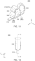
- Patent Document 1 JPA2017-84736 discloses a connector assembly 900 according to the preamble of claim 1.
- the connector assembly 900 comprises a connector 910 and a mating connector 950.
- the mating connector 950 is mateable from a positive Z-side of the connector 910 with the connector 910 which is positioned beyond the mating connector 950 in a negative Z-direction.
- the mating connector 950 comprises a mating housing 952 and mating terminals 954.
- the mating housing 952 holds the mating terminals 954.
- the connector 910 comprises a housing 920 and terminals 930.
- the housing 920 holds the terminals 930.
- each of the terminals 930 has a fixed portion 932, a held portion 934, a supporting portion 936 and a contact point 938.
- the fixed portion 932 is configured to be fixed on an object (not shown).
- the held portion 934 is held by the housing 920.
- the supporting portion 936 extends from the held portion 934 and is resiliently deformable.
- the contact point 938 is supported by the supporting portion 936. The contact point 938 is brought into contact with the mating terminal 954 under a mated state where the connector 910 and the mating connector 950 are mated with each other.
- a negative Z-side of the supporting portion 936 of the terminal 930 is not covered with the housing 920. Accordingly, when the connector 910 is mounted on an object, the supporting portion 936 of the terminal 930 and the object face each other in a Z-direction. Due to manufacturing variation of the housing 920 in each connector 910 or to variation in assembly of each connector 910, there occurs a difference among the connectors 910 in a distance between the supporting portion 936 of the terminal 930 and the object when the connector 910 is mounted on the object.
- the connector 910 might be different from other connectors 910 in presence or absence of contact of the supporting portion 936 of the terminal 930 with the object upon the mating of the mating connector 950 with the connector 910 mounted on the object. Additionally, a timing of the contact of the supporting portion 936 of the terminal 930 of each connector 910 with the object might be different from those of other connectors 910 even among the connectors 910 in each of which the supporting portion 936 of the terminal 930 is brought into contact with the object upon the mating of the mating connector 950 with the connector 910 mounted on the object. In other words, each connector 910 exhibits a variation in movement of the terminal 930 upon the mating of the mating connector 950 with the connector 910 mounted on the object.
- One aspect of the present invention provides a connector assembly comprising a mating connector and a connector which is configured to be mounted on an object.
- the mating connector is mateable from above with the connector which is positioned below the mating connector in an up-down direction.
- the mating connector comprises a mating housing and a mating terminal.
- the mating housing holds the mating terminal.
- the connector comprises a housing and a terminal.
- the housing holds the terminal.
- the terminal has a fixed portion, a held portion, a coupling portion, a supporting portion and a contact point.
- the fixed portion is configured to be fixed to the object.
- the held portion is held by the housing.
- the coupling portion couples the fixed portion and the held portion with each other.
- the coupling portion has a receiving portion.
- the supporting portion extends from the held portion and is resiliently deformable.
- the supporting portion has an abutment portion.
- the abutment portion is positioned above the receiving portion in the up-down direction.
- the abutment portion is in contact with the receiving portion under a mated state where the connector and the mating connector are mated with each other.
- the contact point is supported by the supporting portion. The contact point is brought into contact with the mating terminal under the mated state.
- the connector assembly of the present invention is configured as follows: the terminal of the connector has the coupling portion and the supporting portion; the coupling portion has the receiving portion; the supporting portion has the abutment portion; and the abutment portion is in contact with the receiving portion under the mated state where the connector and the mating connector are mated with each other. Accordingly, the connector assembly of the present invention exhibits no variation in movement of the terminal of the connector when the connector and the mating connector are mated with each other. Since the present invention has the aforementioned advantage, the present invention is applicable to a connector assembly comprising a so-called drop-in connector.
- a connector assembly 600 according to a first embodiment of the present invention comprises a mating connector 500 and a connector 100 which is configured to be mounted on an object 700.
- the object 700 of the present embodiment is a circuit board.
- the connector 100 and the object 700 form an electronic equipment 800.
- the mating connector 500 of the present embodiment is mateable from above with the connector 100 which is positioned below the mating connector 500 in an up-down direction.
- the up-down direction is a Z-direction. Specifically, upward is a positive Z-direction while downward is a negative Z-direction.
- the mating connector 500 comprises a mating housing 520 and a plurality of mating terminals 530.
- the present invention is not limited thereto. Specifically, the number of the mating terminal 530 may be one.
- the mating housing 520 of the present embodiment is made of insulator.
- the mating housing 520 holds the mating terminals 530.
- the mating housing 520 has an accommodating portion 522.
- the accommodating portion 522 of the present embodiment is a recess which is recessed upward in the up-down direction.
- each of the mating terminals 530 of the present embodiment is made of metal.
- the mating terminals 530 are arranged in two rows in a first horizontal direction.
- the first horizontal direction is an X-direction.
- the first horizontal direction is also referred to as a front-rear direction. Specifically, it is assumed that forward is a positive X-direction while rearward is a negative X-direction.
- the mating terminals 530 of each row are arranged in a second horizontal direction. In the present embodiment, the second horizontal direction is a Y-direction.
- a part of each of the mating terminals 530 is exposed in the accommodating portion 522.
- the connector 100 of the present embodiment comprises a housing 200 and a plurality of terminals 300.
- the present invention is not limited thereto.
- the number of the terminal 300 may be one.
- the housing 200 of the present embodiment is made of insulator.
- the housing 200 holds the terminals 300.
- a part of the housing 200 is accommodated in the accommodating portion 522 of the mating connector 500 when the connector 100 and the mating connector 500 are mated with each other.
- the housing 200 has a plurality of terminal accommodating portions 210 and a plurality of connection guiding surfaces 220.
- the present invention is not limited thereto. Specifically, the number of the connection guiding surfaces 220 may be two.
- each of the terminal accommodating portions 210 of the present embodiment opens downward in the up-down direction.
- Each of the terminal accommodating portions 210 opens outward in the first horizontal direction.
- each of the terminal accommodating portions 210 has an opening 212 which is positioned at its outer end in the first horizontal direction.
- Each of terminal accommodating portions 210 has a holding portion 214.
- the housing 200 has a plurality of the holding portions 214.
- the holding portion 214 of the present embodiment is a set of ditches which are positioned at opposite ends, respective, of the terminal accommodating portion 210 in the second horizontal direction.
- each of the connection guiding surfaces 220 of the present embodiment extends in a plane which is defined by the up-down direction and the second horizontal direction.
- Each of the connection guiding surfaces 220 is perpendicular to the first horizontal direction.
- Two of the connection guiding surfaces 220 are positioned at opposite sides, respectively, of the opening 212 in the second horizontal direction.
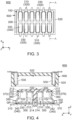
- the terminals 300 of the present embodiment is made of metal. As shown in Fig. 4 , the terminals 300 are held by the housing 200. As shown in Fig. 3 , the terminals 300 are arranged in two rows, namely, a front row and a rear row, in the first horizontal direction. The terminals 300 of each row are arranged in the second horizontal direction.
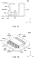
- each of the terminals 300 of the present embodiment has a fixed portion 310, a held portion 320, a coupling portion 330, a supporting portion 340 and a contact point 360.
- the fixed portion 310 of the present embodiment extends outward from an outer end of the coupling portion 330.
- the fixed portion 310 defines a lower end of the terminal 300 in the up-down direction.
- the fixed portion 310 defines an outer end of the terminal 300 in the first horizontal direction.
- the fixed portion 310 is configured to be fixed to the object 700.
- the held portion 320 of the present embodiment defines an inner end of the terminal 300 in the first horizontal direction.
- the held portion 320 extends upward in the up-down direction from the coupling portion 330.
- the held portion 320 is held by the housing 200. Specifically, the held portion 320 is held by the holding portion 214. More specifically, the held portion 320 is press-fit into the holding portion 214.
- the coupling portion 330 of the present embodiment extends in a first orientation of the first horizontal direction from the held portion 320.
- the coupling portion 330 extends in a second orientation of the first horizontal direction from the fixed portion 310.
- the first orientation starting from the contact point 360 is away from the held portion 320 while the second orientation starting from the contact point 360 is toward the held portion 320.
- the first orientation is outward in the first horizontal direction while the second orientation is inward in the first horizontal direction.
- the first orientation is forward while the second orientation is rearward.
- the first orientation is rearward while the second orientation is forward.
- the coupling portion 330 couples the fixed portion 310 and the held portion 320 with each other.
- the coupling portion 330 has a receiving portion 332.
- the receiving portion 332 of the present embodiment is positioned around an end portion of the coupling portion 330 in the first orientation.
- the receiving portion 332 is a surface facing upward in the up-down direction.
- the housing 200 does not have a bottom surface which is positioned just below the coupling portion 330.
- the coupling portion 330 is visible when the connector 100 is viewed from below in the up-down direction. This reduces a height of the connector 100 of the present embodiment in comparison with an assumption where the housing 200 have a bottom surface which is positioned just below the coupling portion 330.
- the supporting portion 340 of the present embodiment extends from the held portion 320.
- the supporting portion 340 is resiliently deformable.
- the supporting portion 340 has a first portion 341 and a second portion 343.
- the first portion 341 of the present embodiment defines an upper end of the supporting portion 340 in the up-down direction.
- the first portion 341 extends in the first orientation from the held portion 320 and is bent to extend downward and is further bent to extend in the first orientation and downward.
- the first portion 341 is away from the coupling portion 330 by a distance which is increased toward the held portion 320.
- the first portion 341 has an abutment portion 342.
- the supporting portion 340 has the abutment portion 342.
- the abutment portion 342 of the present embodiment is positioned at an end portion of the first portion 341 in the first orientation.
- the abutment portion 342 is positioned between the held portion 320 and the fixed portion 310 in the first horizontal direction.
- the abutment portion 342 is nearer to the contact point 360 than to the held portion 320 in the first horizontal direction perpendicular to the up-down direction.
- the abutment portion 342 is positioned above the receiving portion 332 in the up-down direction. In the up-down direction, the abutment portion 342 protrudes downward and defines the downward-most position of the supporting portion 340. Since the supporting portion 340 is resiliently deformable as described above, the abutment portion 342 is movable downward in the up-down direction.
- the abutment portion 342 is positioned beyond the connection guiding surface 220 in the first orientation of the first horizontal direction under an unmated state where the connector 100 and the mating connector 500 are not mated with each other.
- the abutment portion 342 is not in contact with the receiving portion 332 under the unmated state where the connector 100 and the mating connector 500 are not mated with each other.
- the connector 100 has a gap GP between the abutment portion 342 and the receiving portion 332 under the unmated state where the connector 100 and the mating connector 500 are not mated with each other.
- the gap GP has a size smaller than a thickness of the object 700.
- the abutment portion 342 is in contact with the receiving portion 332 under a mated state where the connector 100 and the mating connector 500 are mated with each other.
- the receiving portion 332 is provided on the coupling portion 330 coupling the fixed portion 310, which is configured to be fixed to the object 700, with the held portion 320 held by the housing 200. Accordingly, a relative position of the receiving portion 332 in the terminal 300 is hardly changed.
- the abutment portion 342 can be reliably brought into contact with the receiving portion 332 when the connector 100 and the mating connector 500 are mated with each other.
- the connector 100 has the gap GP, which is smaller than the thickness of the object 700, between the abutment portion 342 and the receiving portion 332 under the unmated state where the connector 100 and the mating connector 500 are not mated with each other. Accordingly, when the connector 100 and the mating connector 500 are mated with each other, the abutment portion 342 is brought into contact with the receiving portion 332 at an earlier period in the mating process and thereby a downward movement of the contact point 360 is prevented. In other words, the contact point 360 is moved by a short distance in the up-down direction when the connector 100 and the mating connector 500 are mated with each other.
- the connector assembly 600 of the present embodiment can have an increased effective contact length between the connector 100 and the mating connector 500. This can also reduce a size of the connector 100 in the up-down direction which is needed for the connector assembly 600 having a desired effective contact length. Thus, the connector assembly 600 can have a reduced height.
- the second portion 343 of the present embodiment extends upward in the up-down direction from the first portion 341. Specifically, the second portion 343 is bent from the first portion 341 and extends upward and toward the second orientation and is further bent to extend upward and toward the first orientation.
- the contact point 360 of the present embodiment is positioned at an upper end of the second portion 343.
- the contact point 360 is supported by the supporting portion 340.
- the contact point 360 is movable in the first horizontal direction perpendicular to the up-down direction under the unmated state where the connector 100 and the mating connector 500 are not mated with each other.
- the contact point 360 faces in the first orientation of the first horizontal direction perpendicular to the up-down direction, wherein the first orientation starting from the contact point 360 is away from the held portion 320.
- an orientation, in which the contact point 360 in an initial state should be moved is the second orientation which is opposite to the first orientation.
- the contact point 360 is positioned beyond any of the connection guiding surfaces 220 in the first orientation under the unmated state where the connector 100 and the mating connector 500 are not mated with each other. As shown in Fig. 11 , the contact point 360 is brought into contact with the mating terminal 530 under the mated state where the connector 100 and the mating connector 500 are mated with each other.
- the fixed portion 310, the held portion 320 and the contact point 360 are positioned on a common line parallel to the first horizontal direction. In other words, the fixed portion 310, the held portion 320 and the contact point 360 are positioned at the same location in the second horizontal direction.
- the terminal 300 further has a protruding portion 350.
- the protruding portion 350 of the present embodiment is formed on the supporting portion 340. More specifically, the protruding portion 350 is formed on the second portion 343. The protruding portion 350 is positioned beyond the contact point 360 in the first orientation of the first horizontal direction. The abutment portion 342 is positioned beyond the protruding portion 350 in the second orientation of the first horizontal direction. The receiving portion 332 is positioned beyond the protruding portion 350 in the second orientation of the first horizontal direction.
- the protruding portion 350 is bulged in the first orientation under the unmated state where the connector 100 and the mating connector 500 are not mated with each other.
- the protruding portion 350 is positioned beyond any of the connection guiding surfaces 220 in the first orientation under the unmated state where the connector 100 and the mating connector 500 are not mated with each other.
- the terminal 300 further has a guiding portion 370.
- the guiding portion 370 of the present embodiment is positioned above the contact point 360 in the up-down direction.
- the guiding portion 370 extends in the second orientation of the first horizontal direction and upward in the up-down direction, wherein the second orientation is opposite to the first orientation.
- the two connection guiding surfaces 220 are positioned at opposite outsides, respectively, of the guiding portion 370 in the second horizontal direction which is perpendicular to both the up-down direction and the first horizontal direction.
- the guiding portion 370 has a curved surface 372.
- the curved surface 372 of the present embodiment has an R-shape which is bulged upward and toward the first orientation. As shown in Fig. 4 , the curved surface 372 is positioned at a location same as a location of the connection guiding surface 220 in the first horizontal direction.
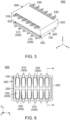
- the connector 100 and the mating connector 500 are arranged as shown in Fig. 4 .
- the mating connector 500 is moved so that the connector 100 and the mating connector 500 approach each other in the up-down direction.
- the mating terminal 530 is brought into contact with the guiding portion 370 of the terminal 300, and the mating of the connector 100 with the mating connector 500 begins.
- the mating connector 500 is further moved so that the connector 100 and the mating connector 500 further approach each other in the up-down direction. Then, the mating terminal 530 is moved on the guiding portion 370 while the mating terminal 530 pushes down the whole of the terminal 300, and the abutment portion 342 begins to be pressed against the receiving portion 332.
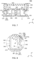
- the connector 100 and the mating connector 500 result in a specific contact state shown in each of Figs. 7 and 8 .
- the mating terminal 530 and the guiding portion 370 are in contact with each other at a specific contact location SP.
- the curved surface 372 of the guiding portion 370 of the terminal 300 is positioned at the specific contact location SP.
- the mating terminal 530 is moved on the guiding portion 370 while the mating terminal 530 pushes down the whole of the terminal 300, and the abutment portion 342 begins to be pressed against the receiving portion 332; and the mating terminal 530 and the guiding portion 370 are brought into contact with each other at the specific contact location SP at the beginning of the abutment portion 342 being pressed against the receiving portion 332.
- the guiding portion 370 receives, from the mating terminal 530, a force which is directed perpendicular to a contact surface where the mating terminal 530 and the guiding portion 370 are in contact with each other.
- the force is referred to as a vertical force VF.
- the guiding portion 370 receives, from the mating terminal 530, the vertical force VF which is directed perpendicular to the contact surface where the mating terminal 530 and the guiding portion 370 are in contact with each other.
- the guiding portion 370 receives another force caused by friction between the mating terminal 530 and the guiding portion 370.
- the force is referred to as a frictional force FF.
- the guiding portion 370 receives, at the specific contact location SP, the frictional force FF caused by friction between the mating terminal 530 and the guiding portion 370 upon the movement of the mating terminal 530 on the guiding portion 370.
- the guiding portion 370 receives a combined force JF of the vertical force VF and the frictional force FF under the specific contact state.
- An action line EL of the combined force JF intersects with the coupling portion 330 at a reference point RP.
- the abutment portion 342 is positioned beyond the reference point RP in the first orientation of the first horizontal direction.
- the guiding portion 370 receives the combined force JF while the abutment portion 342 is positioned beyond the reference point RP in the first orientation. Accordingly, referring to Fig. 8 , a moment M with respect to the abutment portion 342, which moves the guiding portion 370 in the second orientation, is produced at the specific contact location SP.
- the connector 100 of the present embodiment is configured so that the moment M with respect to the abutment portion 342 at the specific contact location SP is directed in the second orientation.
- the connector 100 of the present embodiment is configured so that the orientation, in which the contact point 360 in the initial state should be moved, coincides with the orientation of the moment M with respect to the abutment portion 342 at the specific contact location SP.
- the connector 100 of the present embodiment prevents an increase of a contact pressure between the mating terminal 530 and the terminal 300 upon the mating of the connector 100 with the mating connector 500. Consequently, the connector 100 of the present embodiment prevents buckling of the terminal 300 upon the mating of the connector 100 with the mating connector 500.
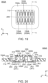
- a connector assembly (not shown) according to a second embodiment of the present invention has a structure similar to that of the connector assembly 600 (see Fig. 1 ) of the aforementioned first embodiment. Accordingly, components similar to those of the first embodiment among components shown in Figs. 18 to 20 will be designated by the same reference numerals as those of the first embodiment. As for directions and orientations in the present embodiment, expressions same as those of the first embodiment will be used hereinbelow.
- the connector assembly of the present embodiment comprises a mating connector (not shown) and a connector 100A which is configured to be mounted on an object 700A having an opening 710.
- the object 700A of the present embodiment is a circuit board.
- the connector 100A and the object 700A form an electronic equipment 800A.
- the mating connector of the present embodiment has a structure same as that of the mating connector 500 of the aforementioned first embodiment. Accordingly, a detailed explanation thereabout is omitted.
- the connector 100A of the present embodiment comprises a housing 200 and a plurality of terminals 300A.
- the present invention is not limited thereto.
- the number of the terminal 300A may be one.
- the housing 200 has a structure same as that of the first embodiment. Accordingly, a detailed explanation thereabout is omitted.
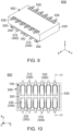
- each of the terminals 300A of the present embodiment is made of metal. As shown in Fig. 19 , the terminals 300A are held by the housing 200. The terminals 300A are arranged in two rows, namely, a front row and a rear row, in the first horizontal direction. The terminals 300A of each row are arranged in the second horizontal direction.
- each of the terminals 300A has a fixed portion 310, a held portion 320, a coupling portion 330A, a supporting portion 340 and a contact point 360.
- the terminal 300A has a structure similar to that of the first embodiment except for the coupling portion 330A. Accordingly, a detailed explanation thereabout is omitted.
- the coupling portion 330A of the present embodiment extends in the first orientation of the first horizontal direction from the held portion 320. More specifically, the coupling portion 330A extends in the first orientation from the held portion 320 and is bent to extend upward and is further bent to extend toward the first orientation.
- the coupling portion 330A extends in the second orientation of the first horizontal direction from the fixed portion 310. More specifically, the coupling portion 330A extends in the second orientation from the fixed portion 310 and is bent to extend downward and is further bent to extend in the second orientation.
- the coupling portion 330A couples the fixed portion 310 and the held portion 320 with each other.
- the coupling portion 330A has a receiving portion 332.
- a part of the connector 100A is positioned in the opening 710 of the object 700A when the connector 100A of the present embodiment is mounted on the object 700A.
- the connector 100A of the present embodiment is a so-called drop-in connector.
- the connector 100A of the present embodiment is configured so that the fixed portion 310 is positioned above any of the receiving portion 332 and an abutment portion 342 in the up-down direction.
- a force applied to the terminal 300A upon the mating of the connector 100A with the mating connector and a moment produced on the terminal 300A upon their mating are similar to those of the aforementioned first embodiment. Accordingly, a detailed explanation thereabout is omitted.
- the connector assembly of the present embodiment also has an effect similar to that of the aforementioned first embodiment.
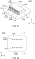
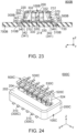
- a connector assembly (not shown) according to a third embodiment of the present invention has a structure similar to that of the connector assembly 600 (see Fig. 1 ) of the aforementioned first embodiment. Accordingly, components similar to those of the first embodiment among components shown in Figs. 21 to 23 will be designated by the same reference numerals as those of the first embodiment. As for directions and orientations in the present embodiment, expressions same as those of the first embodiment will be used hereinbelow.
- the connector assembly of the present embodiment comprises a mating connector (not shown) and a connector 100B which is configured to be mounted on an object 700B having a plurality of through holes 720.
- the object 700B of the present embodiment is a circuit board.
- Each of the through holes 720 pierces the object 700B in the up-down direction.
- the connector 100B and the object 700B form an electronic equipment 800B.
- the mating connector of the present embodiment has a structure same as that of the mating connector 500 of the aforementioned first embodiment. Accordingly, a detailed explanation thereabout is omitted.
- the connector 100B of the present embodiment comprises a housing 200 and a plurality of terminals 300B.
- the present invention is not limited thereto.
- the number of the terminal 300B may be one.
- the housing 200 has a structure same as that of the first embodiment. Accordingly, a detailed explanation thereabout is omitted.
- each of the terminals 300B of the present embodiment is made of metal.
- the terminals 300B are held by the housing 200.
- the terminals 300B are arranged in two rows, namely, a front row and a rear row, in the first horizontal direction.
- the terminals 300B of each row are arranged in the second horizontal direction.
- each of the terminals 300B of the present embodiment has a fixed portion 31 0B, a held portion 320, a coupling portion 330, a supporting portion 340 and a contact point 360.
- the terminal 300B has a structure similar to that of the first embodiment except for the fixed portion 310B. Accordingly, a detailed explanation thereabout is omitted.
- the fixed portion 310B of the present embodiment extends downward in the up-down direction from an outer end of the coupling portion 330 in the first horizontal direction.
- the fixed portion 310B defines a lower end of the terminal 300B in the up-down direction.
- the fixed portion 310B defines an outer end of the terminal 300B in the first horizontal direction.
- the fixed portion 310B is inserted into the through hole 720 of the object 700B to be fixed thereto when the connector 100B is mounted on the object 700B.
- a force applied to the terminal 300B upon the mating of the connector 100B with the mating connector and a moment produced on the terminal 300B upon their mating are similar to those of the aforementioned first embodiment. Accordingly, a detailed explanation thereabout is omitted.
- the connector assembly of the present embodiment also has an effect similar to that of the aforementioned first embodiment.
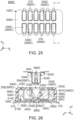
- a connector assembly 600C according to a fourth embodiment of the present invention comprises a mating connector 500C and a connector 100C which is configured to be mounted on an object 700C.
- the object 700C of the present embodiment is a circuit board.
- the connector 100C and the object 700C form an electronic equipment 800C.
- the mating connector 500C of the present embodiment is mateable from above with the connector 100C which is positioned below the mating connector 500C in an up-down direction.
- the up-down direction is a Z-direction. Specifically, upward is a positive Z-direction while downward is a negative Z-direction.
- the mating connector 500C comprises a mating housing 520C and a plurality of mating terminals 530C.
- the present invention is not limited thereto. Specifically, the number of the mating terminal 530C may be one.
- the mating housing 520C of the present embodiment is made of insulator.
- the mating housing 520C holds the mating terminals 530C.
- the mating housing 520C has an island-like portion 524.
- the island-like portion 524 extends downward in the up-down direction.
- the island-like portion 524 defines a lower end of the mating housing 520C in the up-down direction.
- each of the mating terminals 530C of the present embodiment is made of metal. As shown in Fig. 24 , the mating terminals 530C are arranged in two rows in a first horizontal direction. In the present embodiment, the first horizontal direction is an X-direction. The first horizontal direction is also referred to as a front-rear direction. Specifically, it is assumed that forward is a positive X-direction while rearward is a negative X-direction.
- the mating terminals 530C of each row are arranged in a second horizontal direction. In the present embodiment, the second horizontal direction is a Y-direction. A part of each of the mating terminals 530C is exposed to the outside of the mating connector 500C from an outer end of the island-like portion 524 in the first horizontal direction.
- the connector 100C of the present embodiment comprises a housing 200C and a plurality of terminals 300C.
- the present invention is not limited thereto.
- the number of the terminal 300C may be one.
- the housing 200C of the present embodiment is made of insulator.
- the housing 200C holds the terminals 300C.
- the housing 200C has a surrounding portion 202 and a connector-side accommodating portion 204.
- the surrounding portion 202 of the present embodiment defines an outer end of the housing 200C in the first horizontal direction.
- the surrounding portion 202 defines an outer end of the housing 200C in the second horizontal direction.
- the surrounding portion 202 surrounds the connector-side accommodating portion 204 in a direction perpendicular to the up-down direction.
- the surrounding portion 202 has a plurality of terminal accommodating portions 210C and a plurality of connection guiding surfaces 220C.
- the present invention is not limited thereto. Specifically, the number of the connection guiding surfaces 220C may be two.
- each of the terminal accommodating portions 210C of the present embodiment opens downward in the up-down direction.
- Each of the terminal accommodating portions 210C communicates with the connector-side accommodating portion 204 in the first horizontal direction.
- Each of the terminal accommodating portions 210C opens inward in the first horizontal direction.
- each of the terminal accommodating portions 210C has an opening 212C which is positioned at its inner end in the first horizontal direction.
- each of terminal accommodating portions 210C has a holding portion 214C. In other words, the housing 200C has a plurality of the holding portions 214C.
- the holding portion 214C of the present embodiment is a set of ditches which are positioned at opposite ends, respective, of the terminal accommodating portion 210C in the second horizontal direction.
- each of the connection guiding surfaces 220C of the present embodiment extends in a plane which is defined by the up-down direction and the second horizontal direction.
- Each of the connection guiding surfaces 220C is perpendicular to the first horizontal direction.
- Two of the connection guiding surfaces 220C are positioned at opposite sides, respectively, of the opening 212C in the second horizontal direction.
- the connector-side accommodating portion 204 of the present embodiment is a recess which is recessed downward in the up-down direction.
- a part of the mating connector 500C is accommodated in the connector-side accommodating portion 204 of the connector 100C when the connector 100C and the mating connector 500C are mated with each other.
- the island-like portion 524 of the mating connector 500C is accommodated in the connector-side accommodating portion 204 of the connector 100C when the connector 100C and the mating connector 500C are mated with each other,
- each of the terminals 300C of the present embodiment is made of metal.
- the terminals 300C are held by the housing 200C.
- the terminals 300C are arranged in two rows, namely, a front row and a rear row, in the first horizontal direction.
- the terminals 300C of each row are arranged in the second horizontal direction.
- each of the terminals 300C of the present embodiment has a fixed portion 310, a held portion 320C, a coupling portion 330C, a supporting portion 340C and a contact point 360C.
- the fixed portion 310 of the present embodiment is configured to be fixed to the object 700C.
- the fixed portion 310 has a structure same as that of the first embodiment. Accordingly, a detailed explanation thereabout is omitted.
- the held portion 320C of the present embodiment extends upward in the up-down direction from the coupling portion 330C.
- the held portion 320C is held by the housing 200C.
- the held portion 320C is held by the holding portion 214C. More specifically, the held portion 320C is press-fit into the holding portion 214C.
- the coupling portion 330C of the present embodiment extends in a first orientation of the first horizontal direction from the held portion 320C and is bent to extend in a second orientation of the first horizontal direction.
- the coupling portion 330C extends in the first orientation of the first horizontal direction from the fixed portion 310 and is bent to extend in the second orientation of the first horizontal direction.
- the first orientation starting from the contact point 360C is away from the held portion 320C while the second orientation starting from the contact point 360C is toward the held portion 320C.
- the first orientation is inward in the first horizontal direction while the second orientation is outward in the first horizontal direction.
- the first orientation is rearward while the second orientation is forward.
- the first orientation is forward while the second orientation is rearward.
- the coupling portion 330C couples the fixed portion 310 and the held portion 320C with each other.
- the coupling portion 330C has a receiving portion 332C.
- the receiving portion 332C of the present embodiment is positioned around an end portion of the coupling portion 330C in the first orientation.
- the receiving portion 332C is a surface facing upward in the up-down direction.
- the housing 200C does not have a bottom surface which is positioned just below the coupling portion 330C.
- the coupling portion 330C is visible when the connector 100C is viewed from below in the up-down direction. This reduces a height of the connector 100C of the present embodiment in comparison with an assumption where the housing 200C have a bottom surface which is positioned just below the coupling portion 330C.
- the supporting portion 340C of the present embodiment extends from the held portion 320C.
- the supporting portion 340C is resiliently deformable.
- the supporting portion 340C has a first portion 341C and a second portion 343C.
- the first portion 341C of the present embodiment defines an upper end of the supporting portion 340C in the up-down direction.
- the first portion 341C extends in the first orientation from the held portion 320C and is bent to extend downward and is further bent to extend in the first orientation and downward.
- the first portion 341C is away from the coupling portion 330C by a distance which is increased toward the held portion 320C.
- the first portion 341C has an abutment portion 342C.
- the supporting portion 340C has the abutment portion 342C.
- the abutment portion 342C of the present embodiment is positioned at an end portion of the first portion 341C in the first orientation.
- the abutment portion 342C is nearer to the contact point 360C than to the held portion 320C in the first horizontal direction perpendicular to the up-down direction.
- the abutment portion 342C is positioned above the receiving portion 332C in the up-down direction.
- the abutment portion 342C protrudes downward and defines the downward-most position of the supporting portion 340C. Since the supporting portion 340C is resiliently deformable as described above, the abutment portion 342C is movable downward in the up-down direction.
- the abutment portion 342C is positioned beyond the connection guiding surface 220C in the first orientation of the first horizontal direction under an unmated state where the connector 100C and the mating connector 500C are not mated with each other.
- the abutment portion 342C is not in contact with the receiving portion 332C under the unmated state where the connector 100 and the mating connector 500 are not mated with each other.
- the connector 100C has a gap GPC between the abutment portion 342C and the receiving portion 332C under the unmated state where the connector 100 and the mating connector 500 are not mated with each other.
- the gap GPC has a size smaller than a thickness of the object 700C.
- the abutment portion 342C is in contact with the receiving portion 332C under a mated state where the connector 100C and the mating connector 500C are mated with each other.
- the receiving portion 332C is provided on the coupling portion 330C coupling the fixed portion 310, which is configured to be fixed to the object 700C, with the held portion 320C held by the housing 200C. Accordingly, a relative position of the receiving portion 332C in the terminal 300C is hardly changed.
- the abutment portion 342C can be reliably brought into contact with the receiving portion 332C when the connector 100C and the mating connector 500C are mated with each other.
- the connector 100C has the gap GPC, which is smaller than the thickness of the object 700C, between the abutment portion 342C and the receiving portion 332C under the unmated state where the connector 100 and the mating connector 500 are not mated with each other. Accordingly, when the connector 100C and the mating connector 500C are mated with each other, the abutment portion 342C is brought into contact with the receiving portion 332C at an earlier period in the mating process and thereby a downward movement of the contact point 360C is prevented. In other words, the contact point 360C is moved by a short distance in the up-down direction when the connector 100C and the mating connector 500C are mated with each other.
- the connector assembly 600C of the present embodiment can have an increased effective contact length between the connector 100C and the mating connector 500C.
- the second portion 343C of the present embodiment extends upward in the up-down direction from the first portion 341C. Specifically, the second portion 343C is bent from the first portion 341C and extends upward and toward the second orientation and is further bent to extend upward and toward the first orientation.
- the contact point 360C of the present embodiment is positioned at an upper end of the second portion 343C.
- the contact point 360C is supported by the supporting portion 340C.
- the contact point 360C is movable in the first horizontal direction perpendicular to the up-down direction under the unmated state where the connector 100C and the mating connector 500C are not mated with each other.
- the contact point 360C faces in the first orientation of the first horizontal direction perpendicular to the up-down direction, wherein the first orientation starting from the contact point 360C is away from the held portion 320C.
- an orientation, in which the contact point 360C in an initial state should be moved is the second orientation which is opposite to the first orientation.
- the contact point 360C is positioned beyond any of the connection guiding surfaces 220C in the first orientation under the unmated state where the connector 100C and the mating connector 500C are not mated with each other.
- the contact point 360C is brought into contact with the mating terminal 530C under the mated state where the connector 100C and the mating connector 500C are mated with each other.
- the fixed portion 310, the held portion 320C and the contact point 360C are positioned on a common line parallel to the first horizontal direction.
- the fixed portion 310, the held portion 320C and the contact point 360C are positioned at the same location in the second horizontal direction.
- the terminal 300C further has a protruding portion 350C.
- the protruding portion 350C of the present embodiment is formed on the supporting portion 340C. More specifically, the protruding portion 350C is formed on the second portion 343C. The protruding portion 350C is positioned beyond the contact point 360C in the first orientation of the first horizontal direction. The abutment portion 342C is positioned beyond the protruding portion 350C in the second orientation of the first horizontal direction. The receiving portion 332C is positioned beyond the protruding portion 350C in the second orientation of the first horizontal direction.
- the protruding portion 350C is bulged in the first orientation under the unmated state where the connector 100C and the mating connector 500C are not mated with each other.
- the protruding portion 350C is positioned beyond any of the connection guiding surfaces 220C in the first orientation under the unmated state where the connector 100C and the mating connector 500C are not mated with each other.
- the terminal 300C further has a guiding portion 370C.
- the guiding portion 370C of the present embodiment is positioned above the contact point 360C in the up-down direction.
- the guiding portion 370C extends in the second orientation of the first horizontal direction and upward in the up-down direction, wherein the second orientation is opposite to the first orientation.
- the two connection guiding surfaces 220C are positioned at opposite outsides, respectively, of the guiding portion 370C in the second horizontal direction which is perpendicular to both the up-down direction and the first horizontal direction.
- the guiding portion 370C has a curved surface 372C.
- the curved surface 372C of the present embodiment has an R-shape which is bulged upward and toward the first orientation.
- the curved surface 372C is positioned at a location same as a location of the connection guiding surface 220C in the first horizontal direction.
- a force applied to the terminal 300C upon the mating of the connector 100C with the mating connector 500C and a moment produced on the terminal 300C upon their mating are substantially similar to those of the first embodiment. Accordingly, a detailed explanation thereabout is omitted.
- the connector assembly 600C of the present embodiment also has an effect similar to that of the aforementioned first embodiment.
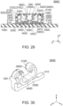
- the configurations of the terminals 300, 300A, 300B, 300C of the connectors 100, 100A, 100B, 100C are not limited thereto and may be modified as follows.
- a terminal 300D of a modification has a fixed portion 310, a held portion 320, a coupling portion 330D, a supporting portion 340D and a contact point 360D.
- the fixed portion 310 and the held portion 320 of the present modification have structures similar to those of the fixed portion 310 and the held portion 320 of the terminal 300 of the aforementioned embodiment. Accordingly, a detailed explanation thereabout is omitted.
- the coupling portion 330D of the present modification extends from the fixed portion 310 to the held portion 320.
- the coupling portion 330D couples the fixed portion 310 and the held portion 320 with each other.
- the coupling portion 330D has a receiving portion 332D.
- the receiving portion 332D of the present modification is a surface facing upward in the up-down direction.
- the receiving portion 332D is provided on the coupling portion 330D coupling the fixed portion 310, which is configured to be fixed to an object (not shown), with the held portion 320 held by a housing (not shown).
- the supporting portion 340D of the present modification extends from the held portion 320.
- the supporting portion 340D is resiliently deformable.
- the supporting portion 340D has an abutment portion 342D.
- the abutment portion 342D of the present modification is positioned between the held portion 320 and the fixed portion 310 in the first horizontal direction.
- the abutment portion 342D is positioned above the receiving portion 332D in the up-down direction.
- the abutment portion 342D protrudes downward and defines the downward-most position of the supporting portion 340D. Since the supporting portion 340D is resiliently deformable as described above, the abutment portion 342D is movable downward in the up-down direction.
- the abutment portion 342D is not in contact with the receiving portion 332D under an unmated state where a connector (not shown), which comprises the terminals 300D, and a mating connector (not shown) are not mated with each other.
- the connector has a gap GPD between the abutment portion 342D and the receiving portion 332D under the unmated state where the connector, which comprises the terminals 300D, and the mating connector are not mated with each other.
- the abutment portion 342D is in contact with the receiving portion 332D under a mated state where the connector, which comprises the terminals 300D, and the mating connector are mated with each other.
- the receiving portion 332D is provided on the coupling portion 330D coupling the fixed portion 310, which is configured to be fixed to the object (not shown), with the held portion 320 held by the housing (not shown). Accordingly, a relative position of the receiving portion 332D in the terminal 300D is hardly changed.
- the abutment portion 342D can be reliably brought into contact with the receiving portion 332D when the connector, which comprises the terminals 300D, and the mating connector are mated with each other.
- the contact point 360D of the present modification is supported by the supporting portion 340D.
- the contact point 360D is movable in the first horizontal direction perpendicular to the up-down direction under the unmated state where the connector, which comprises the terminals 300D, and the mating connector are not mated with each other.
- the contact point 360D faces in the second orientation of the first horizontal direction perpendicular to the up-down direction, wherein the second orientation starting from the contact point 360D is toward the held portion 320.
- an orientation, in which the contact point 360D in an initial state should be moved is the first orientation which is opposite to the second orientation.
- the contact point 360D is brought into contact with a mating terminal (not shown) under the mated state where the connector, which comprises the terminals 300D, and the mating connector are mated with each other.
- the terminal 300D further has a guiding portion 370D.
- the guiding portion 370D of the present modification is positioned above the contact point 360D in the up-down direction.
- the guiding portion 370D extends in the first orientation of the first horizontal direction and upward in the up-down direction.
- the abutment portion 342, 342C is positioned beyond the connection guiding surface 220, 220C in the first orientation of the first horizontal direction under the unmated state where the connector 100, 100A, 100B, 100C and the mating connector 500, 500C are not mated with each other.
- the present invention is not limited thereto.
- the abutment portion 342, 342C may be positioned at a location same as a location of the connection guiding surface 220, 220C in the first horizontal direction under the unmated state where the connector 100, 100A, 100B, 100C and the mating connector 500, 500C are not mated with each other.
- the connector 100, 100A, 100B, 100C should be configured so that, under the unmated state where the connector 100, 100A, 100B, 100C and the mating connector 500, 500C are not mated with each other, the abutment portion 342, 342C is positioned at the location same as the location of the connection guiding surface 220, 220C in the first horizontal direction or beyond the connection guiding surface 220, 220C in the first orientation of the first horizontal direction.
- the connector 100, 100A, 100B, 100C can reliably prevent buckling of the terminal 300, 300A, 300B, 300C upon the mating of the connector 100, 100A, 100B, 100C with the mating connector 500, 500C.
- the protruding portion 350, 350C is bulged in the first orientation under the unmated state where the connector 100, 100A, 100B, 100C and the mating connector 500, 500C are not mated with each other.
- the present invention is not limited thereto.
- the protruding portion 350, 350C may protrude in the first orientation under the unmated state where the connector 100, 100A, 100B, 100C and the mating connector 500, 500C are not mated with each other.
- the protruding portion 350, 350C should be configured so that, under the unmated state where the connector 100, 100A, 100B, 100C and the mating connector 500, 500C are not mated with each other, the protruding portion 350, 350C protrudes in the first orientation or is bulged in the first orientation.
- the connector 100, 100A, 100B, 100C can further prevent buckling of the terminal 300, 300A, 300B, 300C upon the mating of the connector 100, 100A, 100B, 100C with the mating connector 500, 500C.
- each of the coupling portions 330, 330A, 330C of the terminals 300, 300A, 300B, 300C of the aforementioned embodiments has no portion which is press-fit into the housing 200, 200C
- the present invention is not limited thereto.
- the terminal 300, 300A, 300B, 300C may be modified as follows: instead of having the fixed portion 310, 310B, the terminal 300, 300A, 300B, 300C has a fixed portion 310, 310B which is positioned outward in the first horizontal direction beyond the original location of the fixed portion 310, 310B; and the coupling portion 330, 330A, 330C has a press-fit portion which is press-fit into the housing 200, 200C.
- the receiving portion 332, 332C is positioned between the aforementioned press-fit portion and the held portion 320, 320C in the first horizontal direction.
- the electronic equipment 800, 800A, 800B, 800C comprises the object 700, 700A, 700B, 700C, which is the circuit board, and the connector 100, 100A, 100B ,100C of the connector assembly 600, 600C which is mounted on the circuit board
- the present invention is not limited thereto.
- the electronic equipment 800, 800A, 800B, 800C may, for example, be modified as follows: the housing 200, 200C of the connector 100, 100A, 100B ,100C functions as a floating housing; the object 700, 700A, 700B, 700C functions as a fixed housing; and the connector 100, 100A, 100B ,100C is mounted on the fixed housing.
- the electronic equipment 800, 800A, 800B, 800C may be modified to function as a floating connector. That is, the present invention is also applicable to a floating connector.
Landscapes
- Details Of Connecting Devices For Male And Female Coupling (AREA)
- Coupling Device And Connection With Printed Circuit (AREA)
Applications Claiming Priority (1)
| Application Number | Priority Date | Filing Date | Title |
|---|---|---|---|
| JP2021092054A JP7685877B2 (ja) | 2021-06-01 | 2021-06-01 | コネクタ組立体 |
Publications (2)
| Publication Number | Publication Date |
|---|---|
| EP4099509A1 EP4099509A1 (en) | 2022-12-07 |
| EP4099509B1 true EP4099509B1 (en) | 2023-09-13 |
Family
ID=81595707
Family Applications (1)
| Application Number | Title | Priority Date | Filing Date |
|---|---|---|---|
| EP22172334.9A Active EP4099509B1 (en) | 2021-06-01 | 2022-05-09 | Connector assembly |
Country Status (4)
| Country | Link |
|---|---|
| US (1) | US12218464B2 (enExample) |
| EP (1) | EP4099509B1 (enExample) |
| JP (1) | JP7685877B2 (enExample) |
| CN (1) | CN115441229B (enExample) |
Families Citing this family (2)
| Publication number | Priority date | Publication date | Assignee | Title |
|---|---|---|---|---|
| JP2023137208A (ja) * | 2022-03-18 | 2023-09-29 | 日本航空電子工業株式会社 | コネクタ |
| US20250079735A1 (en) * | 2023-09-05 | 2025-03-06 | Foxconn (Kunshan) Computer Connector Co., Ltd. | Electrical connector assembly with improved mating interfaces |
Family Cites Families (11)
| Publication number | Priority date | Publication date | Assignee | Title |
|---|---|---|---|---|
| JP3051313B2 (ja) | 1994-12-09 | 2000-06-12 | ヒロセ電機株式会社 | 電気コネクタ |
| JP4143092B2 (ja) | 2005-02-23 | 2008-09-03 | 日本航空電子工業株式会社 | コネクタ |
| US7387541B1 (en) | 2007-04-25 | 2008-06-17 | Cheng Uei Precision Industry Co., Ltd. | Battery connector |
| JP2009037970A (ja) | 2007-08-03 | 2009-02-19 | Taiko Denki Co Ltd | ソケット及びコネクタ |
| JP5270703B2 (ja) * | 2011-02-17 | 2013-08-21 | ヒロセ電機株式会社 | 電気コネクタ |
| CN103682738B (zh) * | 2012-09-04 | 2017-12-01 | 泰科电子(上海)有限公司 | 一种连接器及板对板连接器对 |
| JP6635583B2 (ja) | 2015-10-30 | 2020-01-29 | 日本航空電子工業株式会社 | コネクタ及びコネクタ組立体 |
| KR20180111144A (ko) * | 2017-03-31 | 2018-10-11 | 몰렉스 엘엘씨 | 기판 대 기판 커넥터 |
| JP7065400B2 (ja) * | 2018-04-26 | 2022-05-12 | パナソニックIpマネジメント株式会社 | コンタクト、コネクタ及び接続装置 |
| JP7128711B2 (ja) * | 2018-10-09 | 2022-08-31 | 日本航空電子工業株式会社 | コネクタ |
| JP7638764B2 (ja) * | 2021-04-01 | 2025-03-04 | 日本航空電子工業株式会社 | コネクタ |
-
2021
- 2021-06-01 JP JP2021092054A patent/JP7685877B2/ja active Active
-
2022
- 2022-04-28 US US17/731,336 patent/US12218464B2/en active Active
- 2022-05-09 EP EP22172334.9A patent/EP4099509B1/en active Active
- 2022-05-11 CN CN202210512653.2A patent/CN115441229B/zh active Active
Also Published As
| Publication number | Publication date |
|---|---|
| US20220385004A1 (en) | 2022-12-01 |
| JP2022184291A (ja) | 2022-12-13 |
| US12218464B2 (en) | 2025-02-04 |
| JP7685877B2 (ja) | 2025-05-30 |
| EP4099509A1 (en) | 2022-12-07 |
| CN115441229A (zh) | 2022-12-06 |
| CN115441229B (zh) | 2025-12-05 |
Similar Documents
| Publication | Publication Date | Title |
|---|---|---|
| US11552419B2 (en) | Floating connector | |
| US20200313331A1 (en) | Connector | |
| EP4099509B1 (en) | Connector assembly | |
| EP0363170A2 (en) | Elastically supported dual cantilever beam pin-receiving electrical contact | |
| US11309661B2 (en) | Connector assembly | |
| EP3667834B1 (en) | Connector assembly | |
| EP4068523B1 (en) | Connector | |
| US20220115796A1 (en) | Connector | |
| US6814605B2 (en) | Connector having a shielding shell provided with a locking portion | |
| US10541486B2 (en) | Connector assembly and connector | |
| US10797422B2 (en) | Connector | |
| US20190273334A1 (en) | Connector and connector assembly | |
| US12362521B2 (en) | Connector assembly | |
| US20040180576A1 (en) | Connector in which a locking portion to be engaged with a housing is formed inside a contact | |
| US12431649B2 (en) | Mateable surface mount connectors with different distances between contact points | |
| US4869685A (en) | Electrical connector having terminals with positive retention means and improved mating zones | |
| US20230238727A1 (en) | Connector | |
| EP4250493B1 (en) | Floating connector | |
| US12469996B2 (en) | Connector and connector assembly | |
| EP4429037A1 (en) | Structure comprising a contact | |
| US20250118921A1 (en) | Connector and assembly | |
| US20240204457A1 (en) | Connector assembly |
Legal Events
| Date | Code | Title | Description |
|---|---|---|---|
| PUAI | Public reference made under article 153(3) epc to a published international application that has entered the european phase |
Free format text: ORIGINAL CODE: 0009012 |
|
| STAA | Information on the status of an ep patent application or granted ep patent |
Free format text: STATUS: THE APPLICATION HAS BEEN PUBLISHED |
|
| AK | Designated contracting states |
Kind code of ref document: A1 Designated state(s): AL AT BE BG CH CY CZ DE DK EE ES FI FR GB GR HR HU IE IS IT LI LT LU LV MC MK MT NL NO PL PT RO RS SE SI SK SM TR |
|
| STAA | Information on the status of an ep patent application or granted ep patent |
Free format text: STATUS: REQUEST FOR EXAMINATION WAS MADE |
|
| 17P | Request for examination filed |
Effective date: 20230120 |
|
| RBV | Designated contracting states (corrected) |
Designated state(s): AL AT BE BG CH CY CZ DE DK EE ES FI FR GB GR HR HU IE IS IT LI LT LU LV MC MK MT NL NO PL PT RO RS SE SI SK SM TR |
|
| GRAP | Despatch of communication of intention to grant a patent |
Free format text: ORIGINAL CODE: EPIDOSNIGR1 |
|
| STAA | Information on the status of an ep patent application or granted ep patent |
Free format text: STATUS: GRANT OF PATENT IS INTENDED |
|
| RIC1 | Information provided on ipc code assigned before grant |
Ipc: H01R 12/73 20110101ALN20230308BHEP Ipc: H01R 12/71 20110101AFI20230308BHEP |
|
| RIC1 | Information provided on ipc code assigned before grant |
Ipc: H01R 12/73 20110101ALN20230313BHEP Ipc: H01R 12/71 20110101AFI20230313BHEP |
|
| INTG | Intention to grant announced |
Effective date: 20230331 |
|
| RIC1 | Information provided on ipc code assigned before grant |
Ipc: H01R 12/73 20110101ALN20230320BHEP Ipc: H01R 12/71 20110101AFI20230320BHEP |
|
| GRAS | Grant fee paid |
Free format text: ORIGINAL CODE: EPIDOSNIGR3 |
|
| GRAA | (expected) grant |
Free format text: ORIGINAL CODE: 0009210 |
|
| STAA | Information on the status of an ep patent application or granted ep patent |
Free format text: STATUS: THE PATENT HAS BEEN GRANTED |
|
| AK | Designated contracting states |
Kind code of ref document: B1 Designated state(s): AL AT BE BG CH CY CZ DE DK EE ES FI FR GB GR HR HU IE IS IT LI LT LU LV MC MK MT NL NO PL PT RO RS SE SI SK SM TR |
|
| REG | Reference to a national code |
Ref country code: CH Ref legal event code: EP |
|
| REG | Reference to a national code |
Ref country code: DE Ref legal event code: R096 Ref document number: 602022000496 Country of ref document: DE |
|
| REG | Reference to a national code |
Ref country code: IE Ref legal event code: FG4D |
|
| REG | Reference to a national code |
Ref country code: LT Ref legal event code: MG9D |
|
| REG | Reference to a national code |
Ref country code: NL Ref legal event code: MP Effective date: 20230913 |
|
| PG25 | Lapsed in a contracting state [announced via postgrant information from national office to epo] |
Ref country code: GR Free format text: LAPSE BECAUSE OF FAILURE TO SUBMIT A TRANSLATION OF THE DESCRIPTION OR TO PAY THE FEE WITHIN THE PRESCRIBED TIME-LIMIT Effective date: 20231214 |
|
| PG25 | Lapsed in a contracting state [announced via postgrant information from national office to epo] |
Ref country code: SE Free format text: LAPSE BECAUSE OF FAILURE TO SUBMIT A TRANSLATION OF THE DESCRIPTION OR TO PAY THE FEE WITHIN THE PRESCRIBED TIME-LIMIT Effective date: 20230913 Ref country code: RS Free format text: LAPSE BECAUSE OF FAILURE TO SUBMIT A TRANSLATION OF THE DESCRIPTION OR TO PAY THE FEE WITHIN THE PRESCRIBED TIME-LIMIT Effective date: 20230913 Ref country code: NO Free format text: LAPSE BECAUSE OF FAILURE TO SUBMIT A TRANSLATION OF THE DESCRIPTION OR TO PAY THE FEE WITHIN THE PRESCRIBED TIME-LIMIT Effective date: 20231213 Ref country code: LV Free format text: LAPSE BECAUSE OF FAILURE TO SUBMIT A TRANSLATION OF THE DESCRIPTION OR TO PAY THE FEE WITHIN THE PRESCRIBED TIME-LIMIT Effective date: 20230913 Ref country code: LT Free format text: LAPSE BECAUSE OF FAILURE TO SUBMIT A TRANSLATION OF THE DESCRIPTION OR TO PAY THE FEE WITHIN THE PRESCRIBED TIME-LIMIT Effective date: 20230913 Ref country code: HR Free format text: LAPSE BECAUSE OF FAILURE TO SUBMIT A TRANSLATION OF THE DESCRIPTION OR TO PAY THE FEE WITHIN THE PRESCRIBED TIME-LIMIT Effective date: 20230913 Ref country code: GR Free format text: LAPSE BECAUSE OF FAILURE TO SUBMIT A TRANSLATION OF THE DESCRIPTION OR TO PAY THE FEE WITHIN THE PRESCRIBED TIME-LIMIT Effective date: 20231214 Ref country code: FI Free format text: LAPSE BECAUSE OF FAILURE TO SUBMIT A TRANSLATION OF THE DESCRIPTION OR TO PAY THE FEE WITHIN THE PRESCRIBED TIME-LIMIT Effective date: 20230913 |
|
| REG | Reference to a national code |
Ref country code: AT Ref legal event code: MK05 Ref document number: 1612256 Country of ref document: AT Kind code of ref document: T Effective date: 20230913 |
|
| PG25 | Lapsed in a contracting state [announced via postgrant information from national office to epo] |
Ref country code: NL Free format text: LAPSE BECAUSE OF FAILURE TO SUBMIT A TRANSLATION OF THE DESCRIPTION OR TO PAY THE FEE WITHIN THE PRESCRIBED TIME-LIMIT Effective date: 20230913 |
|
| PG25 | Lapsed in a contracting state [announced via postgrant information from national office to epo] |
Ref country code: IS Free format text: LAPSE BECAUSE OF FAILURE TO SUBMIT A TRANSLATION OF THE DESCRIPTION OR TO PAY THE FEE WITHIN THE PRESCRIBED TIME-LIMIT Effective date: 20240113 |
|
| PG25 | Lapsed in a contracting state [announced via postgrant information from national office to epo] |
Ref country code: AT Free format text: LAPSE BECAUSE OF FAILURE TO SUBMIT A TRANSLATION OF THE DESCRIPTION OR TO PAY THE FEE WITHIN THE PRESCRIBED TIME-LIMIT Effective date: 20230913 |
|
| PG25 | Lapsed in a contracting state [announced via postgrant information from national office to epo] |
Ref country code: ES Free format text: LAPSE BECAUSE OF FAILURE TO SUBMIT A TRANSLATION OF THE DESCRIPTION OR TO PAY THE FEE WITHIN THE PRESCRIBED TIME-LIMIT Effective date: 20230913 |
|
| PG25 | Lapsed in a contracting state [announced via postgrant information from national office to epo] |
Ref country code: SM Free format text: LAPSE BECAUSE OF FAILURE TO SUBMIT A TRANSLATION OF THE DESCRIPTION OR TO PAY THE FEE WITHIN THE PRESCRIBED TIME-LIMIT Effective date: 20230913 Ref country code: RO Free format text: LAPSE BECAUSE OF FAILURE TO SUBMIT A TRANSLATION OF THE DESCRIPTION OR TO PAY THE FEE WITHIN THE PRESCRIBED TIME-LIMIT Effective date: 20230913 Ref country code: IS Free format text: LAPSE BECAUSE OF FAILURE TO SUBMIT A TRANSLATION OF THE DESCRIPTION OR TO PAY THE FEE WITHIN THE PRESCRIBED TIME-LIMIT Effective date: 20240113 Ref country code: ES Free format text: LAPSE BECAUSE OF FAILURE TO SUBMIT A TRANSLATION OF THE DESCRIPTION OR TO PAY THE FEE WITHIN THE PRESCRIBED TIME-LIMIT Effective date: 20230913 Ref country code: EE Free format text: LAPSE BECAUSE OF FAILURE TO SUBMIT A TRANSLATION OF THE DESCRIPTION OR TO PAY THE FEE WITHIN THE PRESCRIBED TIME-LIMIT Effective date: 20230913 Ref country code: CZ Free format text: LAPSE BECAUSE OF FAILURE TO SUBMIT A TRANSLATION OF THE DESCRIPTION OR TO PAY THE FEE WITHIN THE PRESCRIBED TIME-LIMIT Effective date: 20230913 Ref country code: AT Free format text: LAPSE BECAUSE OF FAILURE TO SUBMIT A TRANSLATION OF THE DESCRIPTION OR TO PAY THE FEE WITHIN THE PRESCRIBED TIME-LIMIT Effective date: 20230913 Ref country code: PT Free format text: LAPSE BECAUSE OF FAILURE TO SUBMIT A TRANSLATION OF THE DESCRIPTION OR TO PAY THE FEE WITHIN THE PRESCRIBED TIME-LIMIT Effective date: 20240115 Ref country code: SK Free format text: LAPSE BECAUSE OF FAILURE TO SUBMIT A TRANSLATION OF THE DESCRIPTION OR TO PAY THE FEE WITHIN THE PRESCRIBED TIME-LIMIT Effective date: 20230913 |
|
| PG25 | Lapsed in a contracting state [announced via postgrant information from national office to epo] |
Ref country code: PL Free format text: LAPSE BECAUSE OF FAILURE TO SUBMIT A TRANSLATION OF THE DESCRIPTION OR TO PAY THE FEE WITHIN THE PRESCRIBED TIME-LIMIT Effective date: 20230913 Ref country code: IT Free format text: LAPSE BECAUSE OF FAILURE TO SUBMIT A TRANSLATION OF THE DESCRIPTION OR TO PAY THE FEE WITHIN THE PRESCRIBED TIME-LIMIT Effective date: 20230913 |
|
| REG | Reference to a national code |
Ref country code: DE Ref legal event code: R097 Ref document number: 602022000496 Country of ref document: DE |
|
| PG25 | Lapsed in a contracting state [announced via postgrant information from national office to epo] |
Ref country code: DK Free format text: LAPSE BECAUSE OF FAILURE TO SUBMIT A TRANSLATION OF THE DESCRIPTION OR TO PAY THE FEE WITHIN THE PRESCRIBED TIME-LIMIT Effective date: 20230913 |
|
| PLBE | No opposition filed within time limit |
Free format text: ORIGINAL CODE: 0009261 |
|
| STAA | Information on the status of an ep patent application or granted ep patent |
Free format text: STATUS: NO OPPOSITION FILED WITHIN TIME LIMIT |
|
| PG25 | Lapsed in a contracting state [announced via postgrant information from national office to epo] |
Ref country code: DK Free format text: LAPSE BECAUSE OF FAILURE TO SUBMIT A TRANSLATION OF THE DESCRIPTION OR TO PAY THE FEE WITHIN THE PRESCRIBED TIME-LIMIT Effective date: 20230913 |
|
| 26N | No opposition filed |
Effective date: 20240614 |
|
| PG25 | Lapsed in a contracting state [announced via postgrant information from national office to epo] |
Ref country code: SI Free format text: LAPSE BECAUSE OF FAILURE TO SUBMIT A TRANSLATION OF THE DESCRIPTION OR TO PAY THE FEE WITHIN THE PRESCRIBED TIME-LIMIT Effective date: 20230913 |
|
| PG25 | Lapsed in a contracting state [announced via postgrant information from national office to epo] |
Ref country code: SI Free format text: LAPSE BECAUSE OF FAILURE TO SUBMIT A TRANSLATION OF THE DESCRIPTION OR TO PAY THE FEE WITHIN THE PRESCRIBED TIME-LIMIT Effective date: 20230913 |
|
| PG25 | Lapsed in a contracting state [announced via postgrant information from national office to epo] |
Ref country code: BG Free format text: LAPSE BECAUSE OF FAILURE TO SUBMIT A TRANSLATION OF THE DESCRIPTION OR TO PAY THE FEE WITHIN THE PRESCRIBED TIME-LIMIT Effective date: 20230913 |
|
| PG25 | Lapsed in a contracting state [announced via postgrant information from national office to epo] |
Ref country code: BG Free format text: LAPSE BECAUSE OF FAILURE TO SUBMIT A TRANSLATION OF THE DESCRIPTION OR TO PAY THE FEE WITHIN THE PRESCRIBED TIME-LIMIT Effective date: 20230913 |
|
| PG25 | Lapsed in a contracting state [announced via postgrant information from national office to epo] |
Ref country code: MC Free format text: LAPSE BECAUSE OF FAILURE TO SUBMIT A TRANSLATION OF THE DESCRIPTION OR TO PAY THE FEE WITHIN THE PRESCRIBED TIME-LIMIT Effective date: 20230913 |
|
| PG25 | Lapsed in a contracting state [announced via postgrant information from national office to epo] |
Ref country code: LU Free format text: LAPSE BECAUSE OF NON-PAYMENT OF DUE FEES Effective date: 20240509 |
|
| PG25 | Lapsed in a contracting state [announced via postgrant information from national office to epo] |
Ref country code: MC Free format text: LAPSE BECAUSE OF FAILURE TO SUBMIT A TRANSLATION OF THE DESCRIPTION OR TO PAY THE FEE WITHIN THE PRESCRIBED TIME-LIMIT Effective date: 20230913 Ref country code: LU Free format text: LAPSE BECAUSE OF NON-PAYMENT OF DUE FEES Effective date: 20240509 |
|
| REG | Reference to a national code |
Ref country code: BE Ref legal event code: MM Effective date: 20240531 |
|
| PG25 | Lapsed in a contracting state [announced via postgrant information from national office to epo] |
Ref country code: IE Free format text: LAPSE BECAUSE OF NON-PAYMENT OF DUE FEES Effective date: 20240509 |
|
| PG25 | Lapsed in a contracting state [announced via postgrant information from national office to epo] |
Ref country code: BE Free format text: LAPSE BECAUSE OF NON-PAYMENT OF DUE FEES Effective date: 20240531 |
|
| PGFP | Annual fee paid to national office [announced via postgrant information from national office to epo] |
Ref country code: DE Payment date: 20250527 Year of fee payment: 4 |
|
| PGFP | Annual fee paid to national office [announced via postgrant information from national office to epo] |
Ref country code: FR Payment date: 20250516 Year of fee payment: 4 |
|
| PG25 | Lapsed in a contracting state [announced via postgrant information from national office to epo] |
Ref country code: CY Free format text: LAPSE BECAUSE OF FAILURE TO SUBMIT A TRANSLATION OF THE DESCRIPTION OR TO PAY THE FEE WITHIN THE PRESCRIBED TIME-LIMIT; INVALID AB INITIO Effective date: 20220509 |
|
| PG25 | Lapsed in a contracting state [announced via postgrant information from national office to epo] |
Ref country code: HU Free format text: LAPSE BECAUSE OF FAILURE TO SUBMIT A TRANSLATION OF THE DESCRIPTION OR TO PAY THE FEE WITHIN THE PRESCRIBED TIME-LIMIT; INVALID AB INITIO Effective date: 20220509 |
|
| REG | Reference to a national code |
Ref country code: CH Ref legal event code: H13 Free format text: ST27 STATUS EVENT CODE: U-0-0-H10-H13 (AS PROVIDED BY THE NATIONAL OFFICE) Effective date: 20251223 |