EP4099453A2 - Fuel cell ship - Google Patents
Fuel cell ship Download PDFInfo
- Publication number
- EP4099453A2 EP4099453A2 EP22175809.7A EP22175809A EP4099453A2 EP 4099453 A2 EP4099453 A2 EP 4099453A2 EP 22175809 A EP22175809 A EP 22175809A EP 4099453 A2 EP4099453 A2 EP 4099453A2
- Authority
- EP
- European Patent Office
- Prior art keywords
- fuel
- compartment
- fuel cell
- tank
- gas
- Prior art date
- Legal status (The legal status is an assumption and is not a legal conclusion. Google has not performed a legal analysis and makes no representation as to the accuracy of the status listed.)
- Pending
Links
- 239000000446 fuel Substances 0.000 title claims abstract description 283
- 239000002828 fuel tank Substances 0.000 claims abstract description 71
- 230000001141 propulsive effect Effects 0.000 claims abstract description 7
- 238000003487 electrochemical reaction Methods 0.000 claims abstract description 5
- 239000002737 fuel gas Substances 0.000 claims description 259
- 239000011261 inert gas Substances 0.000 claims description 61
- 238000004891 communication Methods 0.000 claims description 50
- 238000010248 power generation Methods 0.000 claims description 11
- 231100001261 hazardous Toxicity 0.000 abstract description 22
- 239000007789 gas Substances 0.000 description 137
- 238000001514 detection method Methods 0.000 description 29
- UFHFLCQGNIYNRP-UHFFFAOYSA-N Hydrogen Chemical compound [H][H] UFHFLCQGNIYNRP-UHFFFAOYSA-N 0.000 description 26
- 239000002826 coolant Substances 0.000 description 21
- 230000002093 peripheral effect Effects 0.000 description 13
- XEEYBQQBJWHFJM-UHFFFAOYSA-N Iron Chemical compound [Fe] XEEYBQQBJWHFJM-UHFFFAOYSA-N 0.000 description 10
- 239000007788 liquid Substances 0.000 description 8
- 229920002430 Fibre-reinforced plastic Polymers 0.000 description 6
- 238000001816 cooling Methods 0.000 description 6
- 239000011151 fibre-reinforced plastic Substances 0.000 description 6
- 239000001257 hydrogen Substances 0.000 description 6
- 229910052739 hydrogen Inorganic materials 0.000 description 6
- 239000007787 solid Substances 0.000 description 6
- 238000006243 chemical reaction Methods 0.000 description 5
- 229910052742 iron Inorganic materials 0.000 description 5
- 239000012528 membrane Substances 0.000 description 5
- 239000007800 oxidant agent Substances 0.000 description 5
- 230000001590 oxidative effect Effects 0.000 description 5
- 239000005518 polymer electrolyte Substances 0.000 description 5
- 238000010586 diagram Methods 0.000 description 4
- 238000002474 experimental method Methods 0.000 description 4
- 238000004880 explosion Methods 0.000 description 4
- 239000000463 material Substances 0.000 description 4
- 238000000034 method Methods 0.000 description 4
- 238000005192 partition Methods 0.000 description 4
- 239000000779 smoke Substances 0.000 description 4
- 238000011144 upstream manufacturing Methods 0.000 description 4
- LYCAIKOWRPUZTN-UHFFFAOYSA-N Ethylene glycol Chemical compound OCCO LYCAIKOWRPUZTN-UHFFFAOYSA-N 0.000 description 3
- FAPWRFPIFSIZLT-UHFFFAOYSA-M Sodium chloride Chemical compound [Na+].[Cl-] FAPWRFPIFSIZLT-UHFFFAOYSA-M 0.000 description 3
- 239000003054 catalyst Substances 0.000 description 3
- 238000009792 diffusion process Methods 0.000 description 3
- 239000000428 dust Substances 0.000 description 3
- 238000007667 floating Methods 0.000 description 3
- -1 hydrogen ions Chemical class 0.000 description 3
- 238000012423 maintenance Methods 0.000 description 3
- 230000014759 maintenance of location Effects 0.000 description 3
- 239000002245 particle Substances 0.000 description 3
- 238000012545 processing Methods 0.000 description 3
- 235000002639 sodium chloride Nutrition 0.000 description 3
- 239000011780 sodium chloride Substances 0.000 description 3
- XLYOFNOQVPJJNP-UHFFFAOYSA-N water Substances O XLYOFNOQVPJJNP-UHFFFAOYSA-N 0.000 description 3
- ATUOYWHBWRKTHZ-UHFFFAOYSA-N Propane Chemical compound CCC ATUOYWHBWRKTHZ-UHFFFAOYSA-N 0.000 description 2
- 230000002528 anti-freeze Effects 0.000 description 2
- QVGXLLKOCUKJST-UHFFFAOYSA-N atomic oxygen Chemical group [O] QVGXLLKOCUKJST-UHFFFAOYSA-N 0.000 description 2
- 108010066114 cabin-2 Proteins 0.000 description 2
- 238000004590 computer program Methods 0.000 description 2
- 238000009434 installation Methods 0.000 description 2
- VNWKTOKETHGBQD-UHFFFAOYSA-N methane Chemical compound C VNWKTOKETHGBQD-UHFFFAOYSA-N 0.000 description 2
- 239000001301 oxygen Substances 0.000 description 2
- 229910052760 oxygen Inorganic materials 0.000 description 2
- 238000010926 purge Methods 0.000 description 2
- 230000000717 retained effect Effects 0.000 description 2
- 239000004065 semiconductor Substances 0.000 description 2
- IJGRMHOSHXDMSA-UHFFFAOYSA-N Atomic nitrogen Chemical compound N#N IJGRMHOSHXDMSA-UHFFFAOYSA-N 0.000 description 1
- UGFAIRIUMAVXCW-UHFFFAOYSA-N Carbon monoxide Chemical compound [O+]#[C-] UGFAIRIUMAVXCW-UHFFFAOYSA-N 0.000 description 1
- OTMSDBZUPAUEDD-UHFFFAOYSA-N Ethane Chemical compound CC OTMSDBZUPAUEDD-UHFFFAOYSA-N 0.000 description 1
- WHXSMMKQMYFTQS-UHFFFAOYSA-N Lithium Chemical compound [Li] WHXSMMKQMYFTQS-UHFFFAOYSA-N 0.000 description 1
- 238000004378 air conditioning Methods 0.000 description 1
- 230000005540 biological transmission Effects 0.000 description 1
- 230000000903 blocking effect Effects 0.000 description 1
- OJIJEKBXJYRIBZ-UHFFFAOYSA-N cadmium nickel Chemical compound [Ni].[Cd] OJIJEKBXJYRIBZ-UHFFFAOYSA-N 0.000 description 1
- 229910002091 carbon monoxide Inorganic materials 0.000 description 1
- 229910001873 dinitrogen Inorganic materials 0.000 description 1
- 230000000694 effects Effects 0.000 description 1
- 230000005611 electricity Effects 0.000 description 1
- 230000005484 gravity Effects 0.000 description 1
- 238000007689 inspection Methods 0.000 description 1
- 229910052744 lithium Inorganic materials 0.000 description 1
- 239000001294 propane Substances 0.000 description 1
- 238000009423 ventilation Methods 0.000 description 1
Images


Classifications
-
- H—ELECTRICITY
- H01—ELECTRIC ELEMENTS
- H01M—PROCESSES OR MEANS, e.g. BATTERIES, FOR THE DIRECT CONVERSION OF CHEMICAL ENERGY INTO ELECTRICAL ENERGY
- H01M8/00—Fuel cells; Manufacture thereof
- H01M8/04—Auxiliary arrangements, e.g. for control of pressure or for circulation of fluids
- H01M8/04082—Arrangements for control of reactant parameters, e.g. pressure or concentration
- H01M8/04201—Reactant storage and supply, e.g. means for feeding, pipes
-
- B—PERFORMING OPERATIONS; TRANSPORTING
- B60—VEHICLES IN GENERAL
- B60L—PROPULSION OF ELECTRICALLY-PROPELLED VEHICLES; SUPPLYING ELECTRIC POWER FOR AUXILIARY EQUIPMENT OF ELECTRICALLY-PROPELLED VEHICLES; ELECTRODYNAMIC BRAKE SYSTEMS FOR VEHICLES IN GENERAL; MAGNETIC SUSPENSION OR LEVITATION FOR VEHICLES; MONITORING OPERATING VARIABLES OF ELECTRICALLY-PROPELLED VEHICLES; ELECTRIC SAFETY DEVICES FOR ELECTRICALLY-PROPELLED VEHICLES
- B60L3/00—Electric devices on electrically-propelled vehicles for safety purposes; Monitoring operating variables, e.g. speed, deceleration or energy consumption
- B60L3/0023—Detecting, eliminating, remedying or compensating for drive train abnormalities, e.g. failures within the drive train
- B60L3/0053—Detecting, eliminating, remedying or compensating for drive train abnormalities, e.g. failures within the drive train relating to fuel cells
-
- B—PERFORMING OPERATIONS; TRANSPORTING
- B60—VEHICLES IN GENERAL
- B60L—PROPULSION OF ELECTRICALLY-PROPELLED VEHICLES; SUPPLYING ELECTRIC POWER FOR AUXILIARY EQUIPMENT OF ELECTRICALLY-PROPELLED VEHICLES; ELECTRODYNAMIC BRAKE SYSTEMS FOR VEHICLES IN GENERAL; MAGNETIC SUSPENSION OR LEVITATION FOR VEHICLES; MONITORING OPERATING VARIABLES OF ELECTRICALLY-PROPELLED VEHICLES; ELECTRIC SAFETY DEVICES FOR ELECTRICALLY-PROPELLED VEHICLES
- B60L50/00—Electric propulsion with power supplied within the vehicle
- B60L50/50—Electric propulsion with power supplied within the vehicle using propulsion power supplied by batteries or fuel cells
- B60L50/70—Electric propulsion with power supplied within the vehicle using propulsion power supplied by batteries or fuel cells using power supplied by fuel cells
- B60L50/72—Constructional details of fuel cells specially adapted for electric vehicles
-
- B—PERFORMING OPERATIONS; TRANSPORTING
- B60—VEHICLES IN GENERAL
- B60L—PROPULSION OF ELECTRICALLY-PROPELLED VEHICLES; SUPPLYING ELECTRIC POWER FOR AUXILIARY EQUIPMENT OF ELECTRICALLY-PROPELLED VEHICLES; ELECTRODYNAMIC BRAKE SYSTEMS FOR VEHICLES IN GENERAL; MAGNETIC SUSPENSION OR LEVITATION FOR VEHICLES; MONITORING OPERATING VARIABLES OF ELECTRICALLY-PROPELLED VEHICLES; ELECTRIC SAFETY DEVICES FOR ELECTRICALLY-PROPELLED VEHICLES
- B60L50/00—Electric propulsion with power supplied within the vehicle
- B60L50/50—Electric propulsion with power supplied within the vehicle using propulsion power supplied by batteries or fuel cells
- B60L50/75—Electric propulsion with power supplied within the vehicle using propulsion power supplied by batteries or fuel cells using propulsion power supplied by both fuel cells and batteries
-
- B—PERFORMING OPERATIONS; TRANSPORTING
- B60—VEHICLES IN GENERAL
- B60L—PROPULSION OF ELECTRICALLY-PROPELLED VEHICLES; SUPPLYING ELECTRIC POWER FOR AUXILIARY EQUIPMENT OF ELECTRICALLY-PROPELLED VEHICLES; ELECTRODYNAMIC BRAKE SYSTEMS FOR VEHICLES IN GENERAL; MAGNETIC SUSPENSION OR LEVITATION FOR VEHICLES; MONITORING OPERATING VARIABLES OF ELECTRICALLY-PROPELLED VEHICLES; ELECTRIC SAFETY DEVICES FOR ELECTRICALLY-PROPELLED VEHICLES
- B60L58/00—Methods or circuit arrangements for monitoring or controlling batteries or fuel cells, specially adapted for electric vehicles
- B60L58/30—Methods or circuit arrangements for monitoring or controlling batteries or fuel cells, specially adapted for electric vehicles for monitoring or controlling fuel cells
-
- B—PERFORMING OPERATIONS; TRANSPORTING
- B63—SHIPS OR OTHER WATERBORNE VESSELS; RELATED EQUIPMENT
- B63B—SHIPS OR OTHER WATERBORNE VESSELS; EQUIPMENT FOR SHIPPING
- B63B11/00—Interior subdivision of hulls
- B63B11/02—Arrangement of bulkheads, e.g. defining cargo spaces
-
- B—PERFORMING OPERATIONS; TRANSPORTING
- B63—SHIPS OR OTHER WATERBORNE VESSELS; RELATED EQUIPMENT
- B63B—SHIPS OR OTHER WATERBORNE VESSELS; EQUIPMENT FOR SHIPPING
- B63B11/00—Interior subdivision of hulls
- B63B11/04—Constructional features of bunkers, e.g. structural fuel tanks, or ballast tanks, e.g. with elastic walls
-
- B—PERFORMING OPERATIONS; TRANSPORTING
- B63—SHIPS OR OTHER WATERBORNE VESSELS; RELATED EQUIPMENT
- B63B—SHIPS OR OTHER WATERBORNE VESSELS; EQUIPMENT FOR SHIPPING
- B63B79/00—Monitoring properties or operating parameters of vessels in operation
- B63B79/10—Monitoring properties or operating parameters of vessels in operation using sensors, e.g. pressure sensors, strain gauges or accelerometers
-
- B—PERFORMING OPERATIONS; TRANSPORTING
- B63—SHIPS OR OTHER WATERBORNE VESSELS; RELATED EQUIPMENT
- B63H—MARINE PROPULSION OR STEERING
- B63H21/00—Use of propulsion power plant or units on vessels
- B63H21/12—Use of propulsion power plant or units on vessels the vessels being motor-driven
- B63H21/17—Use of propulsion power plant or units on vessels the vessels being motor-driven by electric motor
-
- B—PERFORMING OPERATIONS; TRANSPORTING
- B63—SHIPS OR OTHER WATERBORNE VESSELS; RELATED EQUIPMENT
- B63H—MARINE PROPULSION OR STEERING
- B63H21/00—Use of propulsion power plant or units on vessels
- B63H21/38—Apparatus or methods specially adapted for use on marine vessels, for handling power plant or unit liquids, e.g. lubricants, coolants, fuels or the like
-
- B—PERFORMING OPERATIONS; TRANSPORTING
- B63—SHIPS OR OTHER WATERBORNE VESSELS; RELATED EQUIPMENT
- B63J—AUXILIARIES ON VESSELS
- B63J2/00—Arrangements of ventilation, heating, cooling, or air-conditioning
- B63J2/02—Ventilation; Air-conditioning
-
- H—ELECTRICITY
- H01—ELECTRIC ELEMENTS
- H01M—PROCESSES OR MEANS, e.g. BATTERIES, FOR THE DIRECT CONVERSION OF CHEMICAL ENERGY INTO ELECTRICAL ENERGY
- H01M8/00—Fuel cells; Manufacture thereof
- H01M8/04—Auxiliary arrangements, e.g. for control of pressure or for circulation of fluids
- H01M8/04082—Arrangements for control of reactant parameters, e.g. pressure or concentration
- H01M8/04089—Arrangements for control of reactant parameters, e.g. pressure or concentration of gaseous reactants
-
- H—ELECTRICITY
- H01—ELECTRIC ELEMENTS
- H01M—PROCESSES OR MEANS, e.g. BATTERIES, FOR THE DIRECT CONVERSION OF CHEMICAL ENERGY INTO ELECTRICAL ENERGY
- H01M8/00—Fuel cells; Manufacture thereof
- H01M8/04—Auxiliary arrangements, e.g. for control of pressure or for circulation of fluids
- H01M8/04298—Processes for controlling fuel cells or fuel cell systems
- H01M8/04313—Processes for controlling fuel cells or fuel cell systems characterised by the detection or assessment of variables; characterised by the detection or assessment of failure or abnormal function
- H01M8/0444—Concentration; Density
- H01M8/04447—Concentration; Density of anode reactants at the inlet or inside the fuel cell
-
- H—ELECTRICITY
- H01—ELECTRIC ELEMENTS
- H01M—PROCESSES OR MEANS, e.g. BATTERIES, FOR THE DIRECT CONVERSION OF CHEMICAL ENERGY INTO ELECTRICAL ENERGY
- H01M8/00—Fuel cells; Manufacture thereof
- H01M8/04—Auxiliary arrangements, e.g. for control of pressure or for circulation of fluids
- H01M8/04298—Processes for controlling fuel cells or fuel cell systems
- H01M8/04313—Processes for controlling fuel cells or fuel cell systems characterised by the detection or assessment of variables; characterised by the detection or assessment of failure or abnormal function
- H01M8/0444—Concentration; Density
- H01M8/04455—Concentration; Density of cathode reactants at the inlet or inside the fuel cell
-
- H—ELECTRICITY
- H01—ELECTRIC ELEMENTS
- H01M—PROCESSES OR MEANS, e.g. BATTERIES, FOR THE DIRECT CONVERSION OF CHEMICAL ENERGY INTO ELECTRICAL ENERGY
- H01M8/00—Fuel cells; Manufacture thereof
- H01M8/04—Auxiliary arrangements, e.g. for control of pressure or for circulation of fluids
- H01M8/04298—Processes for controlling fuel cells or fuel cell systems
- H01M8/04694—Processes for controlling fuel cells or fuel cell systems characterised by variables to be controlled
- H01M8/04746—Pressure; Flow
- H01M8/04753—Pressure; Flow of fuel cell reactants
-
- B—PERFORMING OPERATIONS; TRANSPORTING
- B60—VEHICLES IN GENERAL
- B60K—ARRANGEMENT OR MOUNTING OF PROPULSION UNITS OR OF TRANSMISSIONS IN VEHICLES; ARRANGEMENT OR MOUNTING OF PLURAL DIVERSE PRIME-MOVERS IN VEHICLES; AUXILIARY DRIVES FOR VEHICLES; INSTRUMENTATION OR DASHBOARDS FOR VEHICLES; ARRANGEMENTS IN CONNECTION WITH COOLING, AIR INTAKE, GAS EXHAUST OR FUEL SUPPLY OF PROPULSION UNITS IN VEHICLES
- B60K15/00—Arrangement in connection with fuel supply of combustion engines or other fuel consuming energy converters, e.g. fuel cells; Mounting or construction of fuel tanks
- B60K15/03—Fuel tanks
- B60K15/04—Tank inlets
-
- B—PERFORMING OPERATIONS; TRANSPORTING
- B60—VEHICLES IN GENERAL
- B60K—ARRANGEMENT OR MOUNTING OF PROPULSION UNITS OR OF TRANSMISSIONS IN VEHICLES; ARRANGEMENT OR MOUNTING OF PLURAL DIVERSE PRIME-MOVERS IN VEHICLES; AUXILIARY DRIVES FOR VEHICLES; INSTRUMENTATION OR DASHBOARDS FOR VEHICLES; ARRANGEMENTS IN CONNECTION WITH COOLING, AIR INTAKE, GAS EXHAUST OR FUEL SUPPLY OF PROPULSION UNITS IN VEHICLES
- B60K15/00—Arrangement in connection with fuel supply of combustion engines or other fuel consuming energy converters, e.g. fuel cells; Mounting or construction of fuel tanks
- B60K15/03—Fuel tanks
- B60K15/03006—Gas tanks
- B60K2015/03019—Filling of gas tanks
-
- B—PERFORMING OPERATIONS; TRANSPORTING
- B60—VEHICLES IN GENERAL
- B60K—ARRANGEMENT OR MOUNTING OF PROPULSION UNITS OR OF TRANSMISSIONS IN VEHICLES; ARRANGEMENT OR MOUNTING OF PLURAL DIVERSE PRIME-MOVERS IN VEHICLES; AUXILIARY DRIVES FOR VEHICLES; INSTRUMENTATION OR DASHBOARDS FOR VEHICLES; ARRANGEMENTS IN CONNECTION WITH COOLING, AIR INTAKE, GAS EXHAUST OR FUEL SUPPLY OF PROPULSION UNITS IN VEHICLES
- B60K15/00—Arrangement in connection with fuel supply of combustion engines or other fuel consuming energy converters, e.g. fuel cells; Mounting or construction of fuel tanks
- B60K15/03—Fuel tanks
- B60K15/04—Tank inlets
- B60K15/05—Inlet covers
- B60K2015/0515—Arrangements for closing or opening of inlet cover
- B60K2015/053—Arrangements for closing or opening of inlet cover with hinged connection to the vehicle body
-
- B—PERFORMING OPERATIONS; TRANSPORTING
- B60—VEHICLES IN GENERAL
- B60L—PROPULSION OF ELECTRICALLY-PROPELLED VEHICLES; SUPPLYING ELECTRIC POWER FOR AUXILIARY EQUIPMENT OF ELECTRICALLY-PROPELLED VEHICLES; ELECTRODYNAMIC BRAKE SYSTEMS FOR VEHICLES IN GENERAL; MAGNETIC SUSPENSION OR LEVITATION FOR VEHICLES; MONITORING OPERATING VARIABLES OF ELECTRICALLY-PROPELLED VEHICLES; ELECTRIC SAFETY DEVICES FOR ELECTRICALLY-PROPELLED VEHICLES
- B60L2200/00—Type of vehicles
- B60L2200/32—Waterborne vessels
-
- B—PERFORMING OPERATIONS; TRANSPORTING
- B63—SHIPS OR OTHER WATERBORNE VESSELS; RELATED EQUIPMENT
- B63H—MARINE PROPULSION OR STEERING
- B63H21/00—Use of propulsion power plant or units on vessels
- B63H2021/003—Use of propulsion power plant or units on vessels the power plant using fuel cells for energy supply or accumulation, e.g. for buffering photovoltaic energy
-
- H—ELECTRICITY
- H01—ELECTRIC ELEMENTS
- H01M—PROCESSES OR MEANS, e.g. BATTERIES, FOR THE DIRECT CONVERSION OF CHEMICAL ENERGY INTO ELECTRICAL ENERGY
- H01M8/00—Fuel cells; Manufacture thereof
- H01M8/10—Fuel cells with solid electrolytes
- H01M2008/1095—Fuel cells with polymeric electrolytes
-
- H—ELECTRICITY
- H01—ELECTRIC ELEMENTS
- H01M—PROCESSES OR MEANS, e.g. BATTERIES, FOR THE DIRECT CONVERSION OF CHEMICAL ENERGY INTO ELECTRICAL ENERGY
- H01M2250/00—Fuel cells for particular applications; Specific features of fuel cell system
- H01M2250/20—Fuel cells in motive systems, e.g. vehicle, ship, plane
-
- Y—GENERAL TAGGING OF NEW TECHNOLOGICAL DEVELOPMENTS; GENERAL TAGGING OF CROSS-SECTIONAL TECHNOLOGIES SPANNING OVER SEVERAL SECTIONS OF THE IPC; TECHNICAL SUBJECTS COVERED BY FORMER USPC CROSS-REFERENCE ART COLLECTIONS [XRACs] AND DIGESTS
- Y02—TECHNOLOGIES OR APPLICATIONS FOR MITIGATION OR ADAPTATION AGAINST CLIMATE CHANGE
- Y02E—REDUCTION OF GREENHOUSE GAS [GHG] EMISSIONS, RELATED TO ENERGY GENERATION, TRANSMISSION OR DISTRIBUTION
- Y02E60/00—Enabling technologies; Technologies with a potential or indirect contribution to GHG emissions mitigation
- Y02E60/30—Hydrogen technology
- Y02E60/50—Fuel cells
-
- Y—GENERAL TAGGING OF NEW TECHNOLOGICAL DEVELOPMENTS; GENERAL TAGGING OF CROSS-SECTIONAL TECHNOLOGIES SPANNING OVER SEVERAL SECTIONS OF THE IPC; TECHNICAL SUBJECTS COVERED BY FORMER USPC CROSS-REFERENCE ART COLLECTIONS [XRACs] AND DIGESTS
- Y02—TECHNOLOGIES OR APPLICATIONS FOR MITIGATION OR ADAPTATION AGAINST CLIMATE CHANGE
- Y02T—CLIMATE CHANGE MITIGATION TECHNOLOGIES RELATED TO TRANSPORTATION
- Y02T70/00—Maritime or waterways transport
- Y02T70/50—Measures to reduce greenhouse gas emissions related to the propulsion system
-
- Y—GENERAL TAGGING OF NEW TECHNOLOGICAL DEVELOPMENTS; GENERAL TAGGING OF CROSS-SECTIONAL TECHNOLOGIES SPANNING OVER SEVERAL SECTIONS OF THE IPC; TECHNICAL SUBJECTS COVERED BY FORMER USPC CROSS-REFERENCE ART COLLECTIONS [XRACs] AND DIGESTS
- Y02—TECHNOLOGIES OR APPLICATIONS FOR MITIGATION OR ADAPTATION AGAINST CLIMATE CHANGE
- Y02T—CLIMATE CHANGE MITIGATION TECHNOLOGIES RELATED TO TRANSPORTATION
- Y02T90/00—Enabling technologies or technologies with a potential or indirect contribution to GHG emissions mitigation
- Y02T90/40—Application of hydrogen technology to transportation, e.g. using fuel cells
Definitions
- the present invention relates to a fuel cell ship.
- Patent Document 1 Japanese Unexamined Patent Application Publication No. 2018-92815
- a fuel cell ship it may be required not to arrange electrical equipment (such as ventilation fans) around a portion through which a flammable fuel gas passes, for example, around a fuel gas filling port. This is because the arranged electrical equipment can ignite the fuel gas.
- electrical equipment such as ventilation fans
- a portion through which the fuel gas passes may be referred to as a hazardous site
- a location around the hazardous site where electrical equipment cannot be arranged may be referred to as a hazardous location.
- the area in which electrical equipment can be arranged becomes narrow. As a result, the degree of freedom of arranging electrical equipment is reduced.
- the present invention has been made to solve the above-described problem, and an object the present invention is to provide a fuel cell ship by which the hazardous location where electrical equipment cannot be arranged is narrowed, and the degree of freedom of arranging the electrical equipment can be increased.
- a fuel cell ship is a fuel cell ship including a fuel cell that generates electric power by an electrochemical reaction of fuel, and a propulsion device that generates propulsive force on a hull by electric power supplied from the fuel cell.
- the fuel cell ship further includes a fuel supply pipe through which the fuel is supplied from a fuel tank housing the fuel to the fuel cell, a duct compartment that houses a part of the fuel supply pipe, a vent pipe that communicates with the duct compartment, and a fuel filling port that serves as an inlet for filling the fuel tank with the fuel.
- the fuel filling port is provided in the duct compartment.
- direction is defined as follows. First, a direction from a stern to a bow of a fuel cell ship is "front”, and a direction from the bow to the stern is “rear”. A horizontal direction perpendicular to a front-rear direction is defined as a left-right direction. At this time, when the fuel cell ship is moving forward, the left side is defined as “left” and the right side is defined as “right” when viewed from the operator.
- the upstream side in the gravity direction perpendicular to the front-back direction and the left-right direction is referred to as "up”, and the downstream side is referred to as "down”.
- FIG. 1 is a rear perspective view illustrating an appearance of the fuel cell ship SH.
- FIG. 2 is an explanatory diagram illustrating a schematic configuration of the fuel cell ship SH.
- the fuel cell ship SH includes a hull 1 and a cabin 2.
- the cabin 2 is arranged on top of the hull 1.
- the fuel cell ship SH further includes a fuel cell system 3, a fuel gas storage unit 4, a storage battery system 5, a propulsion device 6, a plurality of pieces of peripheral equipment 11, and a control device 12.
- a control signal or a high voltage power supply line is indicated by a solid line
- a control signal or a low voltage power supply line is indicated by a dashed line.
- the fuel cell system 3 functions as a main power supply.
- the fuel cell system 3 consumes a fuel gas to generate electric power (specifically, DC electric power).
- the fuel gas is an example of a fuel, for example, a combustible gas.
- the fuel gas is hydrogen gas.
- the fuel cell system 3 supplies generated electric power to the propulsion device 6 and the peripheral equipment 11.
- the fuel cell system 3 can also supply electric power to the storage battery system 5 to charge the storage battery system 5.
- the fuel gas storage unit 4 stores the fuel gas to be supplied to the fuel cell system 3.
- the supply of fuel gas from the fuel gas storage unit 4 to the fuel cell system 3 is performed via a fuel gas supply pipe 32 described later (see FIG. 3 ).
- the storage battery system 5 includes a storage battery.
- the storage battery is, for example, a lithium secondary battery, but may also be a nickel-cadmium storage battery, a nickel-hydrogen storage battery, or the like.
- the storage battery system 5 functions as an auxiliary power source for supplying the stored electric power (specifically, DC electric power) to the propulsion device 6 and the peripheral equipment 11.
- DC electric power the stored electric power
- the storage battery system 5 may supply electric power to the control device 12.
- the propulsion device 6 is driven by electric power supplied from a fuel cell 31 (described later) (see FIG. 3 ) of the fuel cell system 3, and generates a propulsive force on the hull 1. That is, the fuel cell ship SH includes the propulsion device 6 that generates a propulsive force on the hull 1 by the electric power supplied from the fuel cell 31.
- the propulsion device 6 may be driven only by the electric power supplied from the storage battery included in the storage battery system 5, or may be driven by the electric power supplied from both the fuel cell 31 and the storage battery. That is, the propulsion device 6 may be driven by the electric power supplied from at least one of the fuel cell and the storage battery to generate the propulsive force on the hull 1.
- the propulsion device 6 includes an electric power conversion device 6a, a propulsion motor 6b, and a propeller 6c.
- the electric power conversion device 6a converts the electric power supplied from the fuel cell system 3 into electric power according to the specifications of the propulsion motor 6b.
- the electric power conversion device 6a converts DC electric power into AC electric power.
- the electric power conversion device 6a has, for example, an inverter.
- the propulsion motor 6b is driven by electric power (for example, AC electric power) supplied from the electric power conversion device 6a.
- the propulsion motor 6b When the propulsion motor 6b is driven, the rotational force of the propulsion motor 6b is transmitted to the propeller 6c.
- the propeller 6c rotates, and a propulsive force is generated on the hull 1.
- a configuration is also possible in which a marine gear is provided between the propulsion motor 6b and the propeller 6c.
- peripheral equipment 11 examples include a compressor, a solenoid valve, and a pump. Examples of the peripheral equipment 11 also include electrical equipment such as lighting equipment and air conditioning equipment, but the types of peripheral equipment 11 are not particularly limited.
- the control device 12 controls the fuel cell system 3, the fuel gas storage unit 4, the storage battery system 5, the propulsion device 6, and the plurality of pieces of peripheral equipment 11.
- the control device 12 is composed of, for example, one or two or more computers.
- the computer is, for example, a Programmable Logic Controller (PLC), but may also be an Electronic Control Unit (ECU).
- PLC Programmable Logic Controller
- ECU Electronic Control Unit
- the control device 12 is supplied with electric power from a battery (for example, a lead battery) (not illustrated) or the storage battery of the storage battery system 5.
- the control device 12 has a control unit 12a and a storage unit 12b.
- the control unit 12a includes a processor such as a Central Processing Unit (CPU).
- the storage unit 12b includes a storage device and stores data and computer programs.
- the storage unit 12b includes a main storage device such as a semiconductor memory and an auxiliary storage device such as a semiconductor memory, a solid state drive, and/or a hard disk drive.
- the storage unit 12b may also include removable media.
- the storage unit 12b corresponds to an example of a non-transitory computer-readable storage medium.
- the processor of the control unit 12a executes a computer program stored in the storage device of the storage unit 12b, to control the fuel cell system 3, the fuel gas storage unit 4, the storage battery system 5, the propulsion device 6, and the plurality of pieces of peripheral equipment 11.
- FIG. 3 is an explanatory diagram schematically illustrating the internal structure of the fuel cell ship SH.
- the air flow is indicated by a dashed line arrow.
- Each member is illustrated in FIG. 3 in which the right side of the drawing is the bow side and the left side of the drawing is the stern side.
- the position of each member is not limited to the position illustrated in FIG. 3 as long as the connection relationship between each member is maintained.
- the fuel cell ship SH includes an engine room 13 and a fuel room 14.
- the engine room 13 and the fuel room 14 are arranged below a deck 1a of the hull 1.
- the engine room 13 is located on the bow side with respect to the fuel room 14.
- partition walls W1, W2 and W3 are located in order from the bow side to the stern side.
- the engine room 13 is separated from other spaces by the partition walls W1 and W2.
- the fuel room 14 is separated from other spaces by the partition walls W2 and W3.
- the partition walls W1 to W3 are made of, for example, fiber reinforced plastics (FRP), but may be iron plates.
- FRP fiber reinforced plastics
- the fuel cell system 3 of the fuel cell ship SH is located in the engine room 13.
- the fuel cell system 3 includes the fuel cell 31, the fuel gas supply pipe 32, and a fuel cell side shutoff valve 33.
- the fuel cell side shutoff valve 33 is an example of the peripheral equipment 11 (see FIG. 2 ).
- the fuel cell 31 generates electric power (specifically, DC electric power) by an electrochemical reaction between the fuel gas being an example of fuel and an oxidant gas.
- the oxidant gas is air and the oxidant is oxygen. That is, the fuel cell ship SH includes the fuel cell 31 that generates electric power by an electrochemical reaction of fuel.
- the fuel cell 31 is a fuel cell stack composed of a plurality of stacked cells.
- each cell of the fuel cell 31 has a solid polymer electrolyte membrane, an anode electrode, a cathode electrode, and a pair of separators.
- the solid polymer electrolyte membrane is sandwiched between the anode electrode and the cathode electrode.
- the anode electrode is a negative electrode (fuel electrode).
- the anode electrode includes an anode catalyst layer and a gas diffusion layer.
- the cathode electrode is a positive electrode (air electrode).
- the cathode electrode includes a cathode catalyst layer and a gas diffusion layer.
- the anode electrode, the solid polymer electrolyte membrane, and the cathode electrode form a Membrane-Electrode Assembly (MEA).
- MEA Membrane-Electrode Assembly
- the pair of separators sandwich the membrane-electrode assembly.
- Each separator has a plurality of grooves. Each groove of one separator forms a flow path for the fuel gas.
- Each groove of the other separator forms a flow path for the oxidant gas.
- the fuel cell 31 supplies generated electric power to the propulsion device 6 and the peripheral equipment 11 which are illustrated in FIG. 2 .
- the fuel cell 31 may indirectly supply generated electric power to the propulsion device 6 and the peripheral equipment 11 via a circuit such as a DC/DC converter or the like.
- the fuel gas supply pipe 32 is a fuel supply pipe for supplying, to the anode electrode of the fuel cell 31, fuel (for example, the fuel gas) stored in a fuel tank 41 (described later) of the fuel gas storage unit 4. That is, the fuel cell ship SH includes the fuel gas supply pipe 32 as a fuel supply pipe through which fuel is supplied to the fuel cell 31 from the fuel tank 41 that houses the fuel.
- the fuel cell side shutoff valve 33 is an example of a shutoff valve SV that opens or closes the flow path of the fuel gas supply pipe 32.
- the opening and closing of the fuel cell side shutoff valve 33 is controlled by the control unit 12a (see FIG. 2 ). Specifically, the fuel cell side shutoff valve 33 switches between supplying the fuel gas from the fuel tank 41 to the fuel cell 31 and stopping the supply of fuel gas based on the control of the control unit 12a.
- only one fuel cell side shutoff valve 33 is provided in the fuel gas supply pipe 32 in a fuel cell compartment 30 (described later), two or more may be provided.
- the fuel cell ship SH further includes the fuel cell compartment 30.
- the fuel cell compartment 30 is a housing body for housing the fuel cell 31.
- the fuel cell compartment 30 is arranged in the engine room 13.
- the fuel cell compartment 30 has a hollow shape.
- the fuel cell compartment 30 has a hollow and substantially rectangular parallelepiped shape.
- the outer walls of the fuel cell compartment 30 include, for example, a top wall 30a, a bottom wall 30b, a front wall (not illustrated), a back wall (not illustrated), a side wall 30c, and a side wall 30d.
- the top surface, bottom surface, front surface, back surface, and side surfaces of the fuel cell compartment 30 can be arbitrarily determined.
- the shape of the fuel cell compartment 30 is not particularly limited as long as the fuel cell compartment 30 has a space that can house the fuel cell 31.
- the fuel cell compartment 30 can also be considered as a container, chamber, or box for housing the fuel cell 31.
- the material of the outer wall of the fuel cell compartment 30 is, for example, FRP, but may be an iron plate.
- a cell compartment air supply port 30e with an opening is provided on the side wall 30d of the fuel cell compartment 30.
- the cell compartment air supply port 30e is connected to a cell compartment air supply pipe 35, which will be described later.
- the cell compartment air supply port 30e may be provided on an outer wall other than the side wall 30d in the fuel cell compartment 30.
- a cell compartment exhaust port 30f with an opening is provided on the side wall 30c of the fuel cell compartment 30.
- the cell compartment exhaust port 30f communicates with a duct compartment 90, which will be described later.
- the cell compartment exhaust port 30f may be provided on an outer wall other than the side wall 30c in the fuel cell compartment 30.
- the fuel cell compartment 30 has an interior that is a closed space, with the exception of the cell compartment air supply port 30e and the cell compartment exhaust port 30f.
- the fuel cell compartment 30 further houses a cell compartment internal gas detector 34a and a cell compartment internal fire detector 34b.
- the cell compartment internal gas detector 34a is a fuel gas detector arranged inside the fuel cell compartment 30.
- the cell compartment internal gas detector 34a includes a hydrogen gas detection sensor.
- the cell compartment internal gas detector 34a is arranged on an inner surface of the top wall 30a located at an upper part of the fuel cell compartment 30. Hydrogen gas as the fuel gas is lighter than air and rises. Therefore, by arranging the cell compartment internal gas detector 34a on the top wall 30a of the fuel cell compartment 30, a leaked fuel gas can be reliably detected by the cell compartment internal gas detector 34a even if the fuel gas leaks in the fuel cell compartment 30.
- the installation position of the cell compartment internal gas detector 34a may be located on the most downstream side of the flow path through which the fuel gas flows when the fuel gas leaks in the fuel cell compartment 30.
- the control unit 12a can control the fuel cell side shutoff valve 33 provided in the fuel gas supply pipe 32 to stop the supply of fuel gas from the fuel tank 41 to the fuel cell 31.
- the cell compartment internal fire detector 34b is a fire detector arranged inside the fuel cell compartment 30.
- the cell compartment internal fire detector 34b includes, for example, one or more sensors among a smoke sensor for detecting smoke, a heat sensor for detecting heat, and a flame sensor for detecting flame.
- the cell compartment internal fire detector 34b may include a thermocouple type fire detector.
- the cell compartment internal fire detector 34b is arranged on an inner surface of the top wall 30a located at an upper part of the fuel cell compartment 30. In the unlikely event that a fire occurs inside the fuel cell compartment 30, the cell compartment internal fire detector 34b detects the fire and outputs a detection signal indicating that a fire has occurred to the control unit 12a. In this case, the control unit 12a can control the fuel cell side shutoff valve 33 to stop the supply of fuel gas from the fuel tank 41 to the fuel cell 31. As a result, in the fuel cell compartment 30, the risk of explosion due to ignition of the fuel gas can be reduced as much as possible.
- the cell compartment air supply pipe 35 is connected to the fuel cell compartment 30.
- the cell compartment air supply pipe 35 extends from the cell compartment air supply port 30e of the fuel cell compartment 30, to the deck 1a and is exposed from the upper surface of the deck 1a.
- a cell compartment air supply device 36 and a cell compartment external gas detector 37 are arranged at an end portion on the deck 1a side of the cell compartment air supply pipe 35.
- the cell compartment air supply device 36 and the cell compartment external gas detector 37 are located above the deck 1a.
- the cell compartment air supply device 36 includes, for example, an inexpensive non-explosion-proof air supply fan, but may include an explosion-proof air supply fan.
- the drive of the cell compartment air supply device 36 is controlled by the control unit 12a.
- One or more filters may be arranged in the cell compartment air supply device 36. The filter removes, for example, dust or sea salt particles.
- the cell compartment air supply device 36 supplies air outside the fuel cell compartment 30 to the inside of the fuel cell compartment 30 via the cell compartment air supply pipe 35 and the cell compartment air supply port 30e.
- the air inside the fuel cell compartment 30 is discharged to the duct compartment 90 via the cell compartment exhaust port 30f. In this way, the inside of the fuel cell compartment 30 is ventilated.
- combustible gas for example, the fuel gas leaking from the fuel cell 31
- the cell compartment external gas detector 37 detects combustible gas (for example, hydrogen gas floating around the hull 1) flowing into the fuel cell compartment 30 from the outside.
- the cell compartment external gas detector 37 is, for example, a combustible gas sensor such as a hydrogen gas sensor.
- the cell compartment external gas detector 37 is arranged on a side opposite to the cell compartment air supply pipe 35 with respect to the cell compartment air supply device 36, that is, on the upstream side of the air flow from the outside to the inside of the fuel cell compartment 30.
- the cell compartment external gas detector 37 may include a gas sensor that detects a combustible gas other than hydrogen gas. Examples of combustible gases other than hydrogen gas include methane, ethane, propane, and carbon monoxide.
- the cell compartment external gas detector 37 outputs, for example, a detection signal indicating the concentration of combustible gas to the control unit 12a.
- the control unit 12a can determine, based on the detection signal, whether the concentration of the combustible gas is equal to or higher than a standard value. Then, if the concentration is equal to or higher than the standard value, the control unit 12a can close the fuel cell side shutoff valve 33 to stop the supply of fuel gas from the fuel tank 41 to the fuel cell 31.
- the above-mentioned standard value may be determined based on experiments and/or experience.
- the fuel cell ship SH further includes a cooling medium tank 38 and a cooling medium pipe 39.
- the cooling medium tank 38 stores a cooling medium for cooling the fuel cell 31.
- the cooling medium is, for example, an antifreeze liquid having low electrical conductivity.
- the antifreeze liquid is, for example, a liquid obtained by mixing pure water and ethylene glycol in a predetermined ratio.
- the cooling medium tank 38 is sealed, but an upper portion may be open.
- the cooling medium pipe 39 is a pipe for circulating the cooling medium between the fuel cell 31 and a heat exchanger (not illustrated).
- a circulation pump (not illustrated) is also provided at a location along the cooling medium pipe 39.
- the fuel cell 31 is cooled by driving the circulation pump to supply the cooling medium from the heat exchanger to the fuel cell 31 via the cooling medium pipe 39.
- the cooling medium supplied for cooling the fuel cell 31 is also supplied, via the cooling medium pipe 39, to the cooling medium tank 38, at which a volume change due to a temperature change of the cooling medium is absorbed and the amount of the cooling medium liquid is monitored.
- a cooling tank internal gas detector 38a is provided in an upper portion inside the cooling medium tank 38.
- the cooling tank internal gas detector 38a is a fuel gas detector that detects the fuel gas existing in the cooling medium tank 38.
- the fuel gas detection result for example, fuel gas concentration information
- the cooling tank internal gas detector 38a is sent to the control unit 12a.
- control unit 12a determines, based on the detection result of the cooling tank internal gas detector 38a, whether there is a fuel gas leak in the fuel cell 31, and if there is a leak, the control unit 12a can, for example, perform control to stop electric power generation by the fuel cell 31.
- the fuel gas storage unit 4 of the fuel cell ship SH includes the fuel tank 41, a gas filling pipe 42, and a tank side shutoff valve 43.
- the tank side shutoff valve 43 is an example of the peripheral equipment 11.
- the fuel tank 41 stores the fuel (for example, the fuel gas) to be supplied to the fuel cell 31.
- the fuel for example, the fuel gas
- FIG. 3 for convenience, only one fuel tank 41 is illustrated, but the number of fuel tanks 41 is not particularly limited and there may be a plurality of the fuel tanks 41.
- the gas filling pipe 42 is a pipe (fuel filling pipe) for replenishing the fuel tank 41 with fuel (for example, the fuel gas), or filling the fuel tank 41 with an inert gas.
- fuel for example, the fuel gas
- One end side of the gas filling pipe 42 is connected to the fuel tank 41.
- the other end side of the gas filling pipe 42 is branched into two, and these ends are connected to a fuel gas filling port 82 and an inert gas filling port 84, respectively.
- the fuel gas filling port 82 and the inert gas filling port 84 are provided in the duct compartment 90 (particularly, an upper duct compartment 80) described later.
- the above-mentioned inert gas is, for example, nitrogen gas.
- nitrogen gas for example, nitrogen gas.
- a side opposite to the connection side with the fuel cell 31 is connected to the fuel tank 41, and a main valve 41a is provided between the fuel cell 31 and the fuel tank 41. That is, the fuel tank 41 and the fuel cell 31 are connected via the fuel gas supply pipe 32.
- the opening and closing of the main valve 41a of the fuel tank 41 is controlled by the control unit 12a.
- the tank side shutoff valve 43 is an example of a shutoff valve SV that opens or closes the flow path of the fuel gas supply pipe 32.
- the opening and closing of the tank side shutoff valve 43 is controlled by the control unit 12a. More specifically, the tank side shutoff valve 43 switches between supplying the fuel gas from the fuel tank 41 to the fuel cell 31 and stopping the supply of fuel gas based on the control of the control unit 12a.
- the tank side shutoff valve 43 switches between supplying the fuel gas from the fuel tank 41 to the fuel cell 31 and stopping the supply of fuel gas based on the control of the control unit 12a.
- two or more tank side shutoff valves 43 may be provided.
- the fuel cell ship SH further includes the tank compartment 40.
- the tank compartment 40 is a housing body that houses the fuel tank 41.
- the tank compartment 40 is arranged in the fuel room 14.
- the tank compartment 40 has a hollow shape.
- the tank compartment 40 has a hollow and substantially rectangular parallelepiped shape.
- the outer walls of the tank compartment 40 include, for example, a top wall 40a, a bottom wall 40b, a front wall (not illustrated), a back wall (not illustrated), a side wall 40c, and a side wall 40d.
- the top surface, bottom surface, front surface, back surface, and side surfaces of the tank compartment 40 can be arbitrarily determined.
- the shape of the tank compartment 40 is not particularly limited as long as the tank compartment 40 has a space that can house at least one fuel tank 41.
- the tank compartment 40 can also be considered as a container, chamber, or box for housing the fuel tank 41.
- the material of the outer wall of the tank compartment 40 is, for example, FRP, but may be an iron plate.
- a tank compartment air supply port 40e with an opening is provided on the side wall 40c of the tank compartment 40.
- the tank compartment air supply port 40e is connected to a tank compartment air supply pipe 45 described later.
- the tank compartment air supply port 40e may be provided on an outer wall other than the side wall 40c in the tank compartment 40.
- a tank compartment exhaust port 40f with an opening is provided on the top wall 40a of the tank compartment 40.
- the tank compartment exhaust port 40f communicates with a vent pipe 10.
- the vent pipe 10 is a pipe for guiding air inside the tank compartment 40 to the outside of the ship.
- the tank compartment exhaust port 40f may be provided on an outer wall other than the top wall 40a in the tank compartment 40.
- the tank compartment 40 has an interior that is a closed space except for the tank compartment air supply port 40e and the tank compartment exhaust port 40f.
- vent pipes 10 are provided on the left and right sides, respectively.
- the vent pipes 10 are located on the stern side with respect to the center of the hull 1 in the front-rear direction.
- the fuel cell ship SH of the present embodiment includes two fuel cell compartments 30 on the right and left sides and two tank compartments 40 on the right and left sides, and two duct compartments 90 on the right and left sides, which will be described later. That is, the vent pipe 10 located on the left side of the hull 1 is provided corresponding to the fuel cell compartment 30, the tank compartment 40, and the duct compartment 90 located on the left side of the hull 1.
- the vent pipe 10 located on the right side of the hull 1 is provided corresponding to the fuel cell compartment 30, the tank compartment 40, and the duct compartment 90 located on the right side of the hull 1.
- a part of the fuel gas supply pipe 32 described above and the tank side shutoff valve 43 are housed in the tank compartment 40.
- the tank compartment 40 further houses a tank compartment internal gas detector 44a and a tank compartment internal fire detector 44b.
- the tank compartment internal gas detector 44a is a fuel gas detector arranged inside the tank compartment 40.
- the tank compartment internal gas detector 44a includes a hydrogen gas detection sensor.
- the tank compartment internal gas detector 44a is arranged on the top wall 40a located at the upper part of the tank compartment 40 to be close to the tank compartment exhaust port 40f or inside the tank compartment exhaust port 40f. In the unlikely event that the fuel gas leaks from the fuel tank 41 in the tank compartment 40, the leaked fuel gas goes toward the vent pipe 10 through the tank compartment exhaust port 40f. That is, the tank compartment exhaust port 40f is located on the most downstream side of the flow path through which the fuel gas flows when the fuel gas leaks inside the tank compartment 40.
- the tank compartment internal gas detector 44a at a position near the tank compartment exhaust port 40f or inside the tank compartment exhaust port 40f, a fuel gas leaked in the tank compartment 40 can be reliably detected by the tank compartment internal gas detector 44a located on the most downstream side of the flow path, regardless of where the fuel gas leaks.
- the control unit 12a can control the tank side shutoff valve 43 provided in the fuel gas supply pipe 32 to stop the supply of fuel gas from the fuel tank 41 to the fuel cell 31.
- the details of control for opening and closing of the tank side shutoff valve 43 will be described later.
- the tank compartment internal fire detector 44b is a fire detector arranged inside the tank compartment 40.
- the tank compartment internal fire detector 44b includes, for example, one or more sensors among a smoke sensor for detecting smoke, a heat sensor for detecting heat, and a flame sensor for detecting flame.
- the tank compartment internal fire detector 44b may include a thermocouple type fire detector.
- the tank compartment internal fire detector 44b is arranged on an inner surface of the top wall 40a located at an upper part of the tank compartment 40. In the unlikely event that a fire occurs inside the tank compartment 40, the tank compartment internal fire detector 44b detects the fire and outputs a detection signal indicating that a fire has occurred to the control unit 12a. In this case, the control unit 12a can control the tank side shutoff valve 43 to stop the supply of fuel gas from the fuel tank 41 to the fuel cell 31. As a result, in the tank compartment 40, the risk of explosion due to ignition of the fuel gas can be reduced as much as possible.
- the tank compartment air supply pipe 45 is connected to the tank compartment 40.
- the tank compartment air supply pipe 45 extends from the tank compartment air supply port 40e of the tank compartment 40 to the deck 1a, and is exposed from an upper surface of the deck 1a.
- a tank compartment air supply device 46 and a tank compartment external gas detector 47 are arranged at an end portion on the deck 1a side of the tank compartment air supply pipe 45.
- the tank compartment air supply device 46 and the tank compartment external gas detector 47 are located above the deck 1a.
- the tank compartment air supply device 46 includes, for example, an inexpensive non-explosion-proof air supply fan, but may include an explosion-proof air supply fan.
- the drive of the tank compartment air supply device 46 is controlled by the control unit 12a.
- One or more filters may be arranged in the tank compartment air supply device 46. The filter removes, for example, dust or sea salt particles.
- the tank compartment air supply device 46 supplies air outside the tank compartment 40 to the inside of the tank compartment 40 via the tank compartment air supply pipe 45 and the tank compartment air supply port 40e.
- the air inside the tank compartment 40 is discharged to the vent pipe 10 via the tank compartment exhaust port 40f. In this way, the inside of the tank compartment 40 is ventilated. As a result, even if the fuel gas leaks from the fuel tank 41 in the tank compartment 40, the retention of the fuel gas can be suppressed.
- the tank compartment external gas detector 47 detects combustible gas (for example, hydrogen gas floating around the hull 1) flowing into the tank compartment 40 from the outside.
- the tank compartment external gas detector 47 is, for example, a combustible gas sensor such as a hydrogen gas sensor.
- the tank compartment external gas detector 47 is arranged on a side opposite to the tank compartment air supply pipe 45 with respect to the tank compartment air supply device 46, that is, on the upstream side of the air flow from the outside to the inside of the tank compartment 40.
- the tank compartment external gas detector 47 may include a gas sensor that detects a combustible gas other than hydrogen gas.
- the tank compartment external gas detector 47 outputs, for example, a detection signal indicating the concentration of combustible gas to the control unit 12a.
- the control unit 12a can determine, based on the detection signal, whether the concentration of the combustible gas is equal to or higher than a standard value. Then, if the concentration is equal to or higher than the standard value, the control unit 12a can close the tank side shutoff valve 43 to stop the supply of fuel gas from the fuel tank 41 to the fuel cell 31.
- the above-mentioned standard value may be determined based on experiments and/or experience.
- the fuel cell ship SH further includes a lower duct compartment 70 and the upper duct compartment 80.
- the lower duct compartment 70 and the upper duct compartment 80 are collectively referred to as a duct compartment 90.
- the duct compartment 90 is a housing body that houses various pipes.
- the duct compartment 90 houses a part of the fuel gas supply pipe 32.
- the inside of the lower duct compartment 70 and the inside of the upper duct compartment 80 communicate with each other via a duct communication portion 91.
- a duct communication portion 91 details of the lower duct compartment 70 and the upper duct compartment 80 will be described.
- the lower duct compartment 70 is located below the deck 1a. More specifically, the lower duct compartment 70 is arranged in the engine room 13. In the engine room 13, the lower duct compartment 70 is located on the stern side with respect to the fuel cell compartment 30. That is, below the deck 1a, the lower duct compartment 70 is located between the fuel cell compartment 30 and the tank compartment 40.
- the lower duct compartment 70 houses a part of the fuel gas supply pipe 32 and a part of the gas filling pipe 42.
- the "part of the fuel gas supply pipe 32" housed in the lower duct compartment 70 refers to a portion of the fuel gas supply pipe 32 located between the fuel cell compartment 30 and the tank compartment 40.
- the “part of the gas filling pipe 42" housed in the lower duct compartment 70 refers to a portion of the gas filling pipe 42 located between the tank compartment 40 and the upper duct compartment 80.
- the material of the lower duct compartment 70 is, for example, FRP, but may be an iron plate.
- the lower duct compartment 70 has a hollow shape.
- the lower duct compartment 70 has a hollow and substantially rectangular parallelepiped shape.
- the outer walls of the lower duct compartment 70 include, for example, a top wall 70a, a bottom wall 70b, a front wall (not illustrated), a back wall (not illustrated), a side wall 70c, and a side wall 70d.
- the top surface, bottom surface, front surface, back surface, and side surfaces of the lower duct compartment 70 can be arbitrarily determined.
- the shape of the lower duct compartment 70 is not particularly limited as long as the lower duct compartment 70 has a space that can house a part of the fuel gas supply pipe 32 and the like.
- the lower duct compartment 70 can also be regarded as a container, a chamber, or a box for housing a part of the fuel gas supply pipe 32 and the like.
- a lower duct compartment air supply port 70e with an opening is provided in the side wall 70d of the lower duct compartment 70.
- the lower duct compartment air supply port 70e is connected to a lower duct compartment air supply pipe 74 described later.
- the lower duct compartment air supply port 70e may be provided on an outer wall other than the side wall 70d in the lower duct compartment 70.
- a lower duct compartment communication port 70f with an opening is provided in the top wall 70a of the lower duct compartment 70.
- the lower duct compartment communication port 70f communicates with the duct communication portion 91 described above.
- the lower duct compartment communication port 70f may be provided on an outer wall other than the top wall 70a in the lower duct compartment 70.
- a cell compartment communication port 70g with an opening is provided in the side wall 70d of the lower duct compartment 70.
- the cell compartment communication port 70g is connected to the cell compartment exhaust port 30f of the fuel cell compartment 30 described above via a communication pipe 92.
- the cell compartment communication port 70g may be provided on an outer wall other than the side wall 70d in the lower duct compartment 70.
- the communication pipe 92 includes, for example, a double pipe having an inner pipe and an outer pipe.
- Examples of the inner pipe include the fuel gas supply pipe 32.
- the outer pipe is located on the outside of the inner pipe in the radial direction.
- the gas inside the fuel cell compartment 30 travels between the inner pipe and the outer pipe of the communication pipe 92, from the cell compartment exhaust port 30f to the cell compartment communication port 70g of the lower duct compartment 70.
- the lower duct compartment 70 has a closed space inside except for the lower duct compartment air supply port 70e, the lower duct compartment communication port 70f, and the cell compartment communication port 70g.
- the lower duct compartment 70 houses a part of a fuel gas discharge pipe 71.
- the fuel gas discharge pipe 71 is a fuel discharge pipe provided by branching from the fuel gas supply pipe 32 located in the lower duct compartment 70.
- the fuel gas discharge pipe 71 is provided by branching from the fuel gas supply pipe 32 between the two shutoff valves SV.
- the fuel gas discharge pipe 71 is provided by branching from the fuel gas supply pipe 32 between the tank side shutoff valve 43 in the tank compartment 40 and the fuel cell side shutoff valve 33 in the fuel cell compartment 30.
- the fuel gas discharge pipe 71 extends from the inside of the lower duct compartment 70 to the inside of the upper duct compartment 80 via the lower duct compartment communication port 70f and the duct communication portion 91, and further communicates with the inside of the vent pipe 10. Therefore, the "part of the fuel gas discharge pipe 71" housed in the lower duct compartment 70 refers to a portion of the fuel gas discharge pipe 71 located between the point of the branching from the fuel gas supply pipe 32 and the upper duct compartment 80.
- the lower duct compartment 70 further houses a release valve 72.
- the release valve 72 is an on-off valve installed in the fuel gas discharge pipe 71 to open or close the flow path of the fuel gas discharge pipe 71.
- the release valve 72 is an example of peripheral equipment 11. The opening and closing of the release valve 72 are controlled by the control unit 12a.
- the release valve 72 may be installed in the upper duct compartment 80.
- the lower duct compartment 70 further houses a lower duct compartment internal gas detector 73.
- the lower duct compartment internal gas detector 73 is a fuel gas detector arranged inside the lower duct compartment 70.
- the fuel gas is hydrogen gas
- the lower duct compartment internal gas detector 73 includes a hydrogen gas detection sensor.
- the lower duct compartment internal gas detector 73 is arranged on the top wall 70a located at an upper portion of the lower duct compartment 70 to be close to the lower duct compartment communication port 70f or inside the lower duct compartment communication port 70f.
- the leaked fuel gas goes toward the upper duct compartment 80 through the lower duct compartment communication port 70f. That is, the lower duct compartment communication port 70f is located on the most downstream side of the flow path through which the fuel gas flows when the fuel gas leaks in the lower duct compartment 70.
- the lower duct compartment internal gas detector 73 at a position close to the lower duct compartment communication port 70f or inside the lower duct compartment communication port 70f, a fuel gas leaked in the lower duct compartment 70 can be reliably detected by the lower duct compartment internal gas detector 73 located on the most downstream side of the flow path, regardless of where the fuel gas leaks.
- the control unit 12a can perform control described later to stop the electric power generation of the fuel cell 31 based on the detection signal.
- the lower duct compartment 70 may further house a fire detector that detects a fire inside the lower duct compartment 70.
- the lower duct compartment air supply pipe 74 is connected to the lower duct compartment 70.
- the lower duct compartment air supply pipe 74 extends from the lower duct compartment air supply port 70e of the lower duct compartment 70 to the deck 1a and is exposed from the upper surface of the deck 1a.
- a lower duct compartment air supply device 75 and a lower duct compartment external gas detector 76 are arranged at an end portion on the deck 1a side of the lower duct compartment air supply pipe 74.
- the lower duct compartment air supply device 75 and the lower duct compartment external gas detector 76 are located above the deck 1a.
- the lower duct compartment air supply device 75 includes, for example, an inexpensive non-explosion-proof air supply fan, but may include an explosion-proof air supply fan.
- the drive of the lower duct compartment air supply device 75 is controlled by the control unit 12a.
- One or more filters may be arranged in the lower duct compartment air supply device 75. The filter removes, for example, dust or sea salt particles.
- the lower duct compartment air supply device 75 supplies the air outside the lower duct compartment 70 (duct compartment 90) to the inside of the lower duct compartment 70 via the lower duct compartment air supply pipe 74 and the lower duct compartment air supply port 70e.
- the air inside the lower duct compartment 70 is discharged to the upper duct compartment 80 through the lower duct compartment communication port 70f. In this way, the inside of the lower duct compartment 70 is ventilated. As a result, even if the fuel gas leaks from the fuel gas supply pipe 32 in the lower duct compartment 70, retention of the fuel gas can be suppressed.
- the lower duct compartment external gas detector 76 detects combustible gas (for example, hydrogen gas floating around the hull 1) flowing into the duct compartment 90 from the outside.
- the lower duct compartment external gas detector 76 is, for example, a combustible gas sensor such as a hydrogen gas sensor.
- the lower duct compartment external gas detector 76 is arranged on a side opposite to the lower duct compartment air supply pipe 74 with respect to the lower duct compartment air supply device 75, that is, on the upstream side of the air flow from the outside to the inside of the duct compartment 90.
- the lower duct compartment external gas detector 76 may include a gas sensor that detects a combustible gas other than hydrogen gas.
- the lower duct compartment external gas detector 76 outputs, for example, a detection signal indicating the concentration of combustible gas to the control unit 12a.
- the control unit 12a can determine, based on the detection signal, whether the concentration of the combustible gas is equal to or higher than a standard value. Then, if the concentration is equal to or higher than the standard value, the control unit 12a can control the shutoff valves SV to stop the supply of fuel gas from the fuel tank 41 to the fuel cell 31.
- the above-mentioned standard value may be determined based on experiments and/or experience.
- the upper duct compartment 80 is located on the deck 1a. More specifically, the upper duct compartment 80 is arranged on the deck 1a to cover an area partially including the lower duct compartment 70 and the tank compartment 40.
- the upper duct compartment 80 houses a part of the fuel gas discharge pipe 71 and a part of the gas filling pipe 42.
- the "part of the fuel gas discharge pipe 71" housed in the upper duct compartment 80 refers to a portion of the fuel gas discharge pipe 71 that extends from the lower duct compartment 70 toward the vent pipe 10.
- the “part of the gas filling pipe 42" housed in the upper duct compartment 80 refers to a portion of the gas filling pipe 42 that extends from the lower duct compartment 70 to the fuel gas filling port 82 described later.
- the material of the upper duct compartment 80 is, for example, FRP, but may be an iron plate.
- the upper duct compartment 80 has a hollow shape.
- the upper duct compartment 80 has a hollow and substantially rectangular parallelepiped shape.
- the outer walls of the upper duct compartment 80 include, for example, a top wall 80a, a bottom wall 80b, a front wall (not illustrated), a back wall (not illustrated), a side wall 80c, and a side wall 80d.
- the top surface, bottom surface, front surface, back surface, and side surfaces of the upper duct compartment 80 can be arbitrarily determined.
- the shape of the upper duct compartment 80 is not particularly limited as long as the upper duct compartment 80 has a space that can house a part of the fuel gas discharge pipe 71 and the like.
- the upper duct compartment 80 can also be regarded as a container, a chamber, or a box for housing the part of the fuel gas discharge pipe 71 and the like.
- the fuel gas discharge pipe 71 communicates with the inside of the vent pipe 10.
- the gas inside the fuel gas discharge pipe 71 (for example, the fuel gas) flows from an end portion 71a of the fuel gas discharge pipe 71 into the vent pipe 10 and is released from the vent pipe 10 to the outside of the ship.
- the end portion 71a of the fuel gas discharge pipe 71 faces upward, that is, faces the open port side of the vent pipe 10. In this case, the discharge direction of gas discharged from the end portion 71a of the fuel gas discharge pipe 71 is upward.
- the discharged fuel gas reaches the inner wall surface of the vent pipe 10 and then flows downward. This may result in unwanted detection by the tank compartment internal gas detector 44a in the tank compartment 40.
- the end portion 71a of the fuel gas discharge pipe 71 facing upward inside the vent pipe 10 as described above, it is possible to reduce unwanted detection by the tank compartment internal gas detector 44a due to the fuel gas discharged from the end portion 71a.
- An upper duct compartment air supply port 80e with an opening is provided in the bottom wall 80b of the upper duct compartment 80.
- the upper duct compartment air supply port 80e communicates with the duct communication portion 91. Therefore, the upper duct compartment 80 communicates with the lower duct compartment 70 via the upper duct compartment air supply port 80e, the duct communication portion 91, and the lower duct compartment communication port 70f.
- the upper duct compartment air supply port 80e may be provided on an outer wall other than the bottom wall 80b in the upper duct compartment 80.
- the upper duct compartment 80 has a vent pipe communication portion 81.
- the vent pipe communication portion 81 is a pipe by which the inside of the upper duct compartment 80 communicates with the vent pipe 10.
- the vent pipe communication portion 81 is illustrated as having a shape bent upward from the horizontal orientation, but the shape of the vent pipe communication portion 81 is not limited to the shape in FIG. 3 .
- the reason why the vent pipe communication portion 81 is bent upward is similar to the reason why the end portion 71a of the fuel gas discharge pipe 71 is bent upward. That is, the vent pipe communication portion 81 is bent upward to reduce unwanted detection by the tank compartment internal gas detector 44a due to the fuel gas discharged from the vent pipe communication portion 81, which will be described later.
- the vent pipe 10 extends upward from the tank compartment 40 and passes through the interior of the upper duct compartment 80. More specifically, the vent pipe 10 passes through the bottom wall 80b of the upper duct compartment 80, enters the inside of the vent pipe 10, and passes through the top wall 80a. Although the top wall 80a is actually inclined as illustrated in FIG. 1 , the top wall 80a is illustrated as being horizontal in FIG. 3 , for convenience.
- the vent pipe communication portion 81 is provided in the upper duct compartment 80 to penetrate through the side wall of the vent pipe 10. As a result, the upper duct compartment 80 communicates with the vent pipe 10 via the vent pipe communication portion 81.
- the air inside the upper duct compartment 80 is discharged to the outside of the ship through the vent pipe communication portion 81 and the vent pipe 10. In this way, it is possible to ventilate the inside of the upper duct compartment 80. If the fuel gas leaks from the fuel gas discharge pipe 71 in the upper duct compartment 80, the leaked fuel gas is discharged to the outside of the ship through the vent pipe communication portion 81 and the vent pipe 10. In this way, it is possible to prevent the leaked fuel gas from being retained in the upper duct compartment 80.
- the upper duct compartment 80 and the lower duct compartment 70 communicate with each other via the duct communication portion 91.
- (1) air taken into the inside of the lower duct compartment 70 via the lower duct compartment air supply pipe 74, (2) a fuel gas leaked from the fuel gas supply pipe 32 in the lower duct compartment 70 for some reason, and (3) air or a fuel gas discharged from the fuel cell compartment 30 to the lower duct compartment 70 via the communication pipe 92 can be discharged to the outside of the ship via the upper duct compartment 80 and the vent pipe 10. In this way, it is possible to suppress the retention of the fuel gas inside the lower duct compartment 70 and inside the fuel cell compartment 30.
- the fuel gas filling port 82 and a fuel gas check valve 83 are provided in the upper duct compartment 80.
- the fuel gas filling port 82 is a fuel filling port that serves as an inlet for filling the fuel tank 41 with fuel (for example, the fuel gas), and is connected to the gas filling pipe 42.
- the fuel gas check valve 83 is provided in the gas filling pipe 42. More specifically, the fuel gas check valve 83 is located between the point where an inert gas pipe 87 (described later) branches from the gas filling pipe 42 and the fuel gas filling port 82.
- the fuel gas supplied from the fuel gas filling port 82 travels through the fuel gas check valve 83 and the gas filling pipe 42, and is supplied to the fuel tank 41 in the tank compartment 40. As a result, the fuel gas is filled in the fuel tank 41 and stored.
- the fuel gas check valve 83 is provided to prevent backflow of the fuel gas from the fuel tank 41 side to the fuel gas filling port 82.
- the upper duct compartment 80 is further provided with the inert gas filling port 84, an on-off valve 85, an inert gas check valve 86, and the inert gas pipe 87.
- the inert gas filling port 84 is an inlet for filling the fuel tank 41 with an inert gas, and is connected to the inert gas pipe 87.
- the inert gas pipe 87 is provided by branching from the gas filling pipe 42 in the upper duct compartment 80.
- the on-off valve 85 and the inert gas check valve 86 are provided in the inert gas pipe 87. In the inert gas pipe 87, the on-off valve 85 is located between the inert gas filling port 84 and the inert gas check valve 86.
- the on-off valve 85 opens or closes the flow path of the inert gas pipe 87.
- installation of the on-off valve 85 may be omitted.
- inert gas When inert gas is supplied to the inert gas filling port 84 and the on-off valve 85 opens the flow path of the inert gas pipe 87 in a state in which the fuel gas is not supplied to the fuel gas filling port 82, the inert gas is supplied to the fuel tank 41 in the tank compartment 40 through the inert gas check valve 86, and via the inert gas pipe 87 and the gas filling pipe 42.
- the tank side shutoff valve 43 opens the flow path of the fuel gas supply pipe 32
- the fuel cell side shutoff valve 33 closes the flow path of the fuel gas supply pipe 32
- the release valve 72 opens the flow path of the fuel gas discharge pipe 71, whereby the fuel gas remaining in the fuel tank 41 is discharged to the vent pipe 10 via the fuel gas supply pipe 32 and the fuel gas discharge pipe 71.
- the fuel gas can be removed from the fuel tank 41 (purge process).
- the main valve 41 is opened or closed at the right time.
- the fuel gas filling port 82 and the inert gas filling port 84 are provided in the upper duct compartment 80 as described above.
- the fuel gas filling port 82 and a fuel gas filling port lid portion 82a (described later) is considered as one and the inert gas filling port 84 and an inert gas filling port lid portion 84a (described later) is considered as one, it can be said that the fuel gas filling port 82 and the inert gas filling port 84 are located at a boundary surface between the inside and the outside of the upper duct compartment 80.
- the fuel gas filling port 82 and the inert gas filling port 84 are provided in the upper duct compartment 80
- An upper duct compartment internal gas detector 88 is housed in the upper duct compartment 80.
- the upper duct compartment internal gas detector 88 is a fuel gas detector arranged inside the upper duct compartment 80.
- the upper duct compartment internal gas detector 88 includes a hydrogen gas detection sensor.
- the upper duct compartment internal gas detector 88 is arranged on the top wall 80a located in an upper portion of the upper duct compartment 80. Hydrogen gas as the fuel gas is lighter than air and rises. Therefore, if the fuel gas leaks in the upper duct compartment 80, the leaked fuel gas can be reliably detected by the upper duct compartment internal gas detector 88. To more reliably detect the fuel gas leaked in the upper duct compartment 80, the upper duct compartment internal gas detector 88 may be arranged at a position close to the vent pipe communication portion 81.
- the control unit 12a can perform control described later to stop the electric power generation of the fuel cell 31 based on the detection signal.
- the upper duct compartment 80 may further house a fire detector that detects a fire inside the upper duct compartment 80.
- a vent pipe internal gas detector 10a is provided further on the downstream side than a discharge port 81a of the vent pipe communication portion 81.
- the downstream side refers to the downstream side in the air flow direction when the air inside the tank compartment 40 flows inside the vent pipe 10 and is discharged to the outside of the ship.
- the vent pipe internal gas detector 10a includes a diffusion type or suction type hydrogen gas detection sensor. A detection signal from the vent pipe internal gas detector 10a is sent to the control unit 12a.
- the control unit 12a In a state where the control unit 12a outputs a signal (closing signal) for closing the release valve 72, if the vent pipe internal gas detector 10a detects the fuel gas even though the tank compartment internal gas detector 44a and the upper duct compartment internal gas detector 88 do not detect the fuel gas, it is possible to determine that the release valve 72 is not completely blocking the flow path of the fuel gas discharge pipe 71, that is, the release valve 72 is malfunctioning. In this case, by sending a notification to the outside, for example, the control unit 12a can prompt a maintenance person to inspect, repair, or replace the release valve 72.
- the notification to the outside includes a monitor display, output of an alarm sound, transmission of information to an external terminal, and the like.
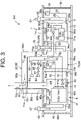
- FIG. 4 is an enlarged perspective view illustrating a portion A in FIG. 1 .
- FIG. 5 is a perspective view of the portion A in FIG. 1 in which the fuel gas filling port lid portion 82a and the inert gas filling port lid portion 84a are not illustrated.
- the fuel gas filling port lid portion 82a is pivotably provided with respect to an upper window portion 82b illustrated in FIG. 5 .
- the fuel gas filling port 82 provided in the upper duct compartment 80 is located inside the upper window portion 82b.
- the fuel gas filling port 82 is exposed to the outside.
- the fuel gas filling port lid portion 82a to close the upper window portion 82b the fuel gas filling port 82 is hidden.
- the fuel cell ship SH navigates in such a state where the fuel gas filling port 82 is hidden by the fuel gas filling port lid portion 82a.
- the inert gas filling port lid portion 84a is pivotably provided with respect to a lower window portion 84b illustrated in FIG. 5 .
- the inert gas filling port 84 and the on-off valve 85 provided in the upper duct compartment 80 are located inside the lower window portion 84b.
- the inert gas filling port lid portion 84a By pivoting the inert gas filling port lid portion 84a to open the lower window portion 84b, the inert gas filling port 84 and the on-off valve 85 are exposed to the outside. As a result, it becomes possible to open the on-off valve 85, and fill the fuel tank 41 with the inert gas via the inert gas filling port 84.
- the inert gas filling port 84 and the on-off valve 85 are hidden.
- the fuel cell ship SH navigates in such a state where the inert gas filling port 84 and the on-off valve 85 are hidden by the inert gas filling port lid portion 84a.
- the fuel cell ship SH includes the duct compartment 90 that houses a part of the fuel gas supply pipe 32 (fuel supply pipe), the vent pipe 10 that communicates (via the vent pipe communication portion 81) with the duct compartment 90 (particularly, the upper duct compartment 80), and the fuel gas filling port 82 (fuel filling port) that serves as an inlet for filling the fuel tank 41 with fuel.
- the fuel gas filling port 82 is provided in the duct compartment 90 (particularly, the upper duct compartment 80).
- the vent pipe 10 and the fuel gas filling port 82 are hazardous sites through which the fuel gas passes.
- various electrical equipment for example, the lower duct compartment air supply device 75 being a non-explosion-proof air supply fan
- the hazardous sites through which the fuel gas passes are concentrated in the duct compartment 90.
- the degree of freedom of arranging various electrical equipment can be increased.
- the fuel cell ship SH includes the fuel gas discharge pipe 71 (fuel discharge pipe) provided by branching from the fuel gas supply pipe 32 (fuel supply pipe), and also includes the gas filling pipe 42 (fuel filling pipe) that connects the fuel gas filling port 82 (fuel filling port) and the fuel tank 41.
- the duct compartment 90 houses the fuel gas discharge pipe 71 and the gas filling pipe 42 (see FIG. 3 ).
- the fuel gas discharge pipe 71 and the gas filling pipe 42 are also hazardous sites through which the fuel gas passes.
- the configuration in which the duct compartment 90 houses the fuel gas discharge pipe 71 and the gas filling pipe 42, which are hazardous sites, together, makes it possible to narrow the hazardous location as compared with a configuration in which these pipes are provided in different locations. Therefore, similar to the above, the degree of freedom of arranging various electrical equipment can be increased.
- the fuel cell ship SH includes the inert gas filling port 84 that serves as an inlet for filling the fuel tank 41 with an inert gas, and also includes the inert gas pipe 87 connected to the inert gas filling port 84 and the gas filling pipe 42.
- the duct compartment 90 further houses the inert gas pipe 87 (see FIG. 3 ).
- the pipes for supplying gas to the fuel tank 41 can be gathered in the duct compartment 90 to realize a compact arrangement. That is, the gas filling pipe 42 for supplying the fuel gas to the fuel tank 41 and the inert gas pipe 87 for supplying the inert gas to the fuel tank 41 can be gathered in the duct compartment 90 to realize a compact arrangement.
- the fuel cell ship SH includes the fuel cell compartment 30 in which the fuel cell 31 is installed, and also includes the communication pipe 92 by which the fuel cell compartment 30 communicates with the duct compartment 90 (for example, the lower duct compartment 70) (see FIG. 3 ).
- the exhaust gas from the fuel cell compartment 30 can be discharged to the duct compartment 90 via the communication pipe 92, and can be discharged from the duct compartment 90 to the outside (for example, the outside of the ship) via the vent pipe 10. Therefore, the total number of vent pipes can be reduced and the configuration can be simplified as compared with the configuration in which a dedicated vent pipe (independent of the other compartments) is separately provided in the fuel cell compartment 30. Even in the unlikely event that the fuel gas leaks in the fuel cell compartment 30, the leaked fuel gas is guided to the duct compartment 90 via the communication pipe 92. That is, the sites through which the leaked fuel gas passes are concentrated in the duct compartment 90. As a result, the hazardous location is narrowed as compared with, for example, a configuration in which a dedicated vent pipe is provided in the fuel cell compartment 30. This makes it possible to further increase the degree of freedom of arranging various electrical equipment.
- the fuel cell ship SH includes the tank compartment 40 in which the fuel tank 41 is installed.
- the vent pipe 10 communicates with both the duct compartment 90 (particularly, the upper duct compartment 80) and the tank compartment 40 (see FIG. 3 ).
- the exhaust gas from the tank compartment 40 can be discharged to the outside (for example, the outside of the ship) via the vent pipe 10.
- the vent pipe 10 for evacuation is shared by the tank compartment 40 and the duct compartment 90, because of which it is possible to reduce the total number of vent pipes as compared with a configuration in which vent pipes are separately provided in the tank compartment 40 and the duct compartment 90, and thus simplify the configuration. Even in the unlikely event that the fuel gas leaks from at least one of the tank compartment 40 and the duct compartment 90, the leaked fuel gas is concentrated in one vent pipe 10 and discharged to the outside.
- the hazardous location is narrowed as compared with, for example, a configuration in which separate vent pipes are provided in the tank compartment 40 and the duct compartment 90 to discharge the fuel gas from the separate vent pipes.
- This makes it possible to further increase the degree of freedom of arranging various electrical equipment.
- the lower duct compartment air supply device 75 is arranged around the duct compartment 90.
- the lower duct compartment air supply device 75 is an example of electrical equipment EM (see FIG. 3 ) arranged around the duct compartment 90. That is, the fuel cell ship SH of the present embodiment includes the electrical equipment EM arranged around the duct compartment 90. In this case, the degree of freedom of arranging the electrical equipment EM around the duct compartment 90 can be increased.
- the electrical equipment EM includes a duct compartment air supply device (lower duct compartment air supply device 75) that supplies air to the inside of the duct compartment 90 (lower duct compartment 70).
- a duct compartment air supply device lower duct compartment air supply device 75
- the degree of freedom of arranging the lower duct compartment air supply device 75 around the duct compartment 90 can be increased.
- fuel gas detectors (the upper duct compartment internal gas detector 88 and the lower duct compartment internal gas detector 73) that detect the fuel gas being the fuel in a gaseous state are installed inside the duct compartment 90.
- the control unit 12a controls the electric power generation of the fuel cell 31 based on the detection signal output from the fuel gas detector. Only the upper duct compartment internal gas detector 88 may be installed in the duct compartment 90. That is, the lower duct compartment internal gas detector 73 may not be installed. This is because hydrogen that has leaked in the lower duct compartment 70 will eventually flow into the upper duct compartment 80 and be detected by the upper duct compartment internal gas detector 88.
- FIG. 6 is a flowchart of processing based on detection of the fuel gas in the duct compartment 90. If the lower duct compartment internal gas detector 73 or the upper duct compartment internal gas detector 88 detects that the concentration of the fuel gas in the lower duct compartment 70 or the upper duct compartment 80 is equal to or higher than the standard value, and the detection signal is sent to the control unit 12a (SI), then the control unit 12a stops the driving of the fuel cell 31 to stop the electric power generation of the fuel cell 31 (S2).
- the standard value for example, 40% LEL can be considered, but the standard value may be appropriately determined based on experiments or experience.
- control unit 12a closes the main valve 41a of the fuel tank 41 (S3). As a result, the supply of fuel gas from the fuel tank 41 to the fuel cell 31 is stopped.
- control unit 12a may also perform a control to close the shutoff valve SV (the tank side shutoff valve 43, the fuel cell side shutoff valve 33) provided in the fuel gas supply pipe 32.
- the fuel cell ship SH includes the control unit 12a that controls the electric power generation of fuel cell 31. If the fuel gas detector (the upper duct compartment internal gas detector 88, the lower duct compartment internal gas detector 73) detects that the concentration of the fuel gas is equal to or higher than a predetermined standard value, the control unit 12a stops the electric power generation of the fuel cell 31 (SI, S2).
- the control unit 12a closes the main valve 41a of the fuel tank 41 (S3). By closing the main valve 41a, the supply of fuel gas from the fuel tank 41 to the fuel cell 31 is stopped, and thus the electric power generation of the fuel cell 31 can be reliably stopped.
- the fuel gas is used as the fuel supplied from the fuel tank 41 to the fuel cell 31, but the fuel is not limited to a gas and may be a liquid.
- a liquid fuel is used, if the liquid fuel leaks from a pipe, the leaked liquid fuel vaporizes and becomes a gas (a fuel gas).
- the present invention can be used, for example, in a fuel cell ship.
Landscapes
- Engineering & Computer Science (AREA)
- Chemical & Material Sciences (AREA)
- Life Sciences & Earth Sciences (AREA)
- Sustainable Energy (AREA)
- Sustainable Development (AREA)
- Mechanical Engineering (AREA)
- Chemical Kinetics & Catalysis (AREA)
- Electrochemistry (AREA)
- General Chemical & Material Sciences (AREA)
- Manufacturing & Machinery (AREA)
- Combustion & Propulsion (AREA)
- Ocean & Marine Engineering (AREA)
- Power Engineering (AREA)
- Transportation (AREA)
- Fuel Cell (AREA)
Abstract
Description
- The present invention relates to a fuel cell ship.
- In the related art, a fuel cell ship in which a fuel gas (for example, hydrogen gas) is supplied from a fuel tank to a fuel cell and a propulsion device is driven by electric power generated by the fuel cell has been proposed (see, for example, Patent Document 1).
- Patent Document 1:
Japanese Unexamined Patent Application Publication No. 2018-92815 - In a fuel cell ship, it may be required not to arrange electrical equipment (such as ventilation fans) around a portion through which a flammable fuel gas passes, for example, around a fuel gas filling port. This is because the arranged electrical equipment can ignite the fuel gas. Hereinafter, a portion through which the fuel gas passes may be referred to as a hazardous site, and a location around the hazardous site where electrical equipment cannot be arranged may be referred to as a hazardous location. In a fuel cell ship, if hazardous sites are scattered, which results in expansion of the hazardous location, the area in which electrical equipment can be arranged becomes narrow. As a result, the degree of freedom of arranging electrical equipment is reduced.
- The present invention has been made to solve the above-described problem, and an object the present invention is to provide a fuel cell ship by which the hazardous location where electrical equipment cannot be arranged is narrowed, and the degree of freedom of arranging the electrical equipment can be increased.
- A fuel cell ship according to an aspect of the present invention is a fuel cell ship including a fuel cell that generates electric power by an electrochemical reaction of fuel, and a propulsion device that generates propulsive force on a hull by electric power supplied from the fuel cell. The fuel cell ship further includes a fuel supply pipe through which the fuel is supplied from a fuel tank housing the fuel to the fuel cell, a duct compartment that houses a part of the fuel supply pipe, a vent pipe that communicates with the duct compartment, and a fuel filling port that serves as an inlet for filling the fuel tank with the fuel. The fuel filling port is provided in the duct compartment.
- According to the above configuration, it is possible to narrow the hazardous location in which electrical equipment cannot be arranged, and increase the degree of freedom of arranging the electric equipment.
-
-
FIG. 1 is a rear perspective view illustrating an appearance of a fuel cell ship according to an embodiment of the present invention. -
FIG. 2 is an explanatory diagram illustrating a schematic configuration of the fuel cell ship. -
FIG. 3 is an explanatory diagram schematically illustrating an internal structure of the fuel cell ship. -
FIG. 4 is an enlarged perspective view illustrating a portion A inFIG. 1 . -
FIG. 5 is a perspective view of the portion A inFIG. 1 in which a fuel gas filling port lid portion and an inert gas filling port lid portion are not illustrated. -
FIG. 6 is a flowchart of processing based on detection of a fuel gas in a duct compartment of the fuel cell ship. - An embodiment of the present invention will be described below based on the drawings. In this description, direction is defined as follows. First, a direction from a stern to a bow of a fuel cell ship is "front", and a direction from the bow to the stern is "rear". A horizontal direction perpendicular to a front-rear direction is defined as a left-right direction. At this time, when the fuel cell ship is moving forward, the left side is defined as "left" and the right side is defined as "right" when viewed from the operator. The upstream side in the gravity direction perpendicular to the front-back direction and the left-right direction is referred to as "up", and the downstream side is referred to as "down".
- Firstly, a fuel cell ship SH according to the present embodiment will be described with reference to
FIGS. 1 and2 .FIG. 1 is a rear perspective view illustrating an appearance of the fuel cell ship SH.FIG. 2 is an explanatory diagram illustrating a schematic configuration of the fuel cell ship SH. The fuel cell ship SH includes a hull 1 and acabin 2. Thecabin 2 is arranged on top of the hull 1. - The fuel cell ship SH further includes a
fuel cell system 3, a fuelgas storage unit 4, a storage battery system 5, apropulsion device 6, a plurality of pieces ofperipheral equipment 11, and a control device 12. InFIG. 2 , a control signal or a high voltage power supply line is indicated by a solid line, and a control signal or a low voltage power supply line is indicated by a dashed line. - The
fuel cell system 3 functions as a main power supply. Thefuel cell system 3 consumes a fuel gas to generate electric power (specifically, DC electric power). The fuel gas is an example of a fuel, for example, a combustible gas. Typically, the fuel gas is hydrogen gas. Thefuel cell system 3 supplies generated electric power to thepropulsion device 6 and theperipheral equipment 11. Thefuel cell system 3 can also supply electric power to the storage battery system 5 to charge the storage battery system 5. - The fuel
gas storage unit 4 stores the fuel gas to be supplied to thefuel cell system 3. The supply of fuel gas from the fuelgas storage unit 4 to thefuel cell system 3 is performed via a fuelgas supply pipe 32 described later (seeFIG. 3 ). - The storage battery system 5 includes a storage battery. The storage battery is, for example, a lithium secondary battery, but may also be a nickel-cadmium storage battery, a nickel-hydrogen storage battery, or the like. The storage battery system 5 functions as an auxiliary power source for supplying the stored electric power (specifically, DC electric power) to the
propulsion device 6 and theperipheral equipment 11. By the storage battery system 5 functioning as an auxiliary power source, it is possible to compensate for a shortage of electric power supplied from thefuel cell system 3 to thepropulsion device 6 or the like. The storage battery system 5 may supply electric power to the control device 12. - The
propulsion device 6 is driven by electric power supplied from a fuel cell 31 (described later) (seeFIG. 3 ) of thefuel cell system 3, and generates a propulsive force on the hull 1. That is, the fuel cell ship SH includes thepropulsion device 6 that generates a propulsive force on the hull 1 by the electric power supplied from thefuel cell 31. - The
propulsion device 6 may be driven only by the electric power supplied from the storage battery included in the storage battery system 5, or may be driven by the electric power supplied from both thefuel cell 31 and the storage battery. That is, thepropulsion device 6 may be driven by the electric power supplied from at least one of the fuel cell and the storage battery to generate the propulsive force on the hull 1. - The
propulsion device 6 includes an electricpower conversion device 6a, apropulsion motor 6b, and apropeller 6c. The electricpower conversion device 6a converts the electric power supplied from thefuel cell system 3 into electric power according to the specifications of thepropulsion motor 6b. For example, the electricpower conversion device 6a converts DC electric power into AC electric power. In this case, the electricpower conversion device 6a has, for example, an inverter. Thepropulsion motor 6b is driven by electric power (for example, AC electric power) supplied from the electricpower conversion device 6a. When thepropulsion motor 6b is driven, the rotational force of thepropulsion motor 6b is transmitted to thepropeller 6c. As a result, thepropeller 6c rotates, and a propulsive force is generated on the hull 1. A configuration is also possible in which a marine gear is provided between thepropulsion motor 6b and thepropeller 6c. - Examples of the
peripheral equipment 11 include a compressor, a solenoid valve, and a pump. Examples of theperipheral equipment 11 also include electrical equipment such as lighting equipment and air conditioning equipment, but the types ofperipheral equipment 11 are not particularly limited. - The control device 12 controls the
fuel cell system 3, the fuelgas storage unit 4, the storage battery system 5, thepropulsion device 6, and the plurality of pieces ofperipheral equipment 11. The control device 12 is composed of, for example, one or two or more computers. The computer is, for example, a Programmable Logic Controller (PLC), but may also be an Electronic Control Unit (ECU). The control device 12 is supplied with electric power from a battery (for example, a lead battery) (not illustrated) or the storage battery of the storage battery system 5. - The control device 12 has a
control unit 12a and a storage unit 12b. Thecontrol unit 12a includes a processor such as a Central Processing Unit (CPU). The storage unit 12b includes a storage device and stores data and computer programs. Specifically, the storage unit 12b includes a main storage device such as a semiconductor memory and an auxiliary storage device such as a semiconductor memory, a solid state drive, and/or a hard disk drive. The storage unit 12b may also include removable media. The storage unit 12b corresponds to an example of a non-transitory computer-readable storage medium. - The processor of the
control unit 12a executes a computer program stored in the storage device of the storage unit 12b, to control thefuel cell system 3, the fuelgas storage unit 4, the storage battery system 5, thepropulsion device 6, and the plurality of pieces ofperipheral equipment 11. - Next, an internal structure of the fuel cell ship SH will be described with reference to
FIG. 3. FIG. 3 is an explanatory diagram schematically illustrating the internal structure of the fuel cell ship SH. InFIG. 3 , the air flow is indicated by a dashed line arrow. Each member is illustrated inFIG. 3 in which the right side of the drawing is the bow side and the left side of the drawing is the stern side. However, the position of each member is not limited to the position illustrated inFIG. 3 as long as the connection relationship between each member is maintained. - The fuel cell ship SH includes an
engine room 13 and afuel room 14. Theengine room 13 and thefuel room 14 are arranged below adeck 1a of the hull 1. Theengine room 13 is located on the bow side with respect to thefuel room 14. Below thedeck 1a, partition walls W1, W2 and W3 are located in order from the bow side to the stern side. Theengine room 13 is separated from other spaces by the partition walls W1 and W2. Thefuel room 14 is separated from other spaces by the partition walls W2 and W3. The partition walls W1 to W3 are made of, for example, fiber reinforced plastics (FRP), but may be iron plates. - The
fuel cell system 3 of the fuel cell ship SH is located in theengine room 13. Thefuel cell system 3 includes thefuel cell 31, the fuelgas supply pipe 32, and a fuel cellside shutoff valve 33. The fuel cellside shutoff valve 33 is an example of the peripheral equipment 11 (seeFIG. 2 ). - The
fuel cell 31 generates electric power (specifically, DC electric power) by an electrochemical reaction between the fuel gas being an example of fuel and an oxidant gas. Typically, the oxidant gas is air and the oxidant is oxygen. That is, the fuel cell ship SH includes thefuel cell 31 that generates electric power by an electrochemical reaction of fuel. - The
fuel cell 31 is a fuel cell stack composed of a plurality of stacked cells. For example, each cell of thefuel cell 31 has a solid polymer electrolyte membrane, an anode electrode, a cathode electrode, and a pair of separators. The solid polymer electrolyte membrane is sandwiched between the anode electrode and the cathode electrode. The anode electrode is a negative electrode (fuel electrode). The anode electrode includes an anode catalyst layer and a gas diffusion layer. The cathode electrode is a positive electrode (air electrode). The cathode electrode includes a cathode catalyst layer and a gas diffusion layer. The anode electrode, the solid polymer electrolyte membrane, and the cathode electrode form a Membrane-Electrode Assembly (MEA). The pair of separators sandwich the membrane-electrode assembly. Each separator has a plurality of grooves. Each groove of one separator forms a flow path for the fuel gas. Each groove of the other separator forms a flow path for the oxidant gas. - In the configuration described above of the
fuel cell 31, hydrogen included in the fuel gas is decomposed into hydrogen ions and electrons by the catalyst on the anode electrode side. Hydrogen ions pass through the solid polymer electrolyte membrane and move to the cathode electrode side. On the other hand, the electrons move to the cathode electrode side through an external circuit. As a result, an electric current is generated (electricity is generated). On the cathode electrode side, oxygen included in the oxidant gas combines with the electrons that flow through the external circuit and hydrogen ions that pass through the solid polymer electrolyte membrane to generate water. The generated water is discharged to the outside of the ship via adischarge pipe 31a. - The
fuel cell 31 supplies generated electric power to thepropulsion device 6 and theperipheral equipment 11 which are illustrated inFIG. 2 . Thefuel cell 31 may indirectly supply generated electric power to thepropulsion device 6 and theperipheral equipment 11 via a circuit such as a DC/DC converter or the like. - The fuel
gas supply pipe 32 is a fuel supply pipe for supplying, to the anode electrode of thefuel cell 31, fuel (for example, the fuel gas) stored in a fuel tank 41 (described later) of the fuelgas storage unit 4. That is, the fuel cell ship SH includes the fuelgas supply pipe 32 as a fuel supply pipe through which fuel is supplied to thefuel cell 31 from thefuel tank 41 that houses the fuel. - The fuel cell
side shutoff valve 33 is an example of a shutoff valve SV that opens or closes the flow path of the fuelgas supply pipe 32. The opening and closing of the fuel cellside shutoff valve 33 is controlled by thecontrol unit 12a (seeFIG. 2 ). Specifically, the fuel cellside shutoff valve 33 switches between supplying the fuel gas from thefuel tank 41 to thefuel cell 31 and stopping the supply of fuel gas based on the control of thecontrol unit 12a. Although only one fuel cellside shutoff valve 33 is provided in the fuelgas supply pipe 32 in a fuel cell compartment 30 (described later), two or more may be provided. - The fuel cell ship SH further includes the
fuel cell compartment 30. Thefuel cell compartment 30 is a housing body for housing thefuel cell 31. Thefuel cell compartment 30 is arranged in theengine room 13. - The
fuel cell compartment 30 has a hollow shape. For example, thefuel cell compartment 30 has a hollow and substantially rectangular parallelepiped shape. In this case, the outer walls of thefuel cell compartment 30 include, for example, atop wall 30a, abottom wall 30b, a front wall (not illustrated), a back wall (not illustrated), aside wall 30c, and a side wall 30d. However, the top surface, bottom surface, front surface, back surface, and side surfaces of thefuel cell compartment 30 can be arbitrarily determined. The shape of thefuel cell compartment 30 is not particularly limited as long as thefuel cell compartment 30 has a space that can house thefuel cell 31. Thefuel cell compartment 30 can also be considered as a container, chamber, or box for housing thefuel cell 31. The material of the outer wall of thefuel cell compartment 30 is, for example, FRP, but may be an iron plate. - A cell compartment
air supply port 30e with an opening is provided on the side wall 30d of thefuel cell compartment 30. The cell compartmentair supply port 30e is connected to a cell compartmentair supply pipe 35, which will be described later. The cell compartmentair supply port 30e may be provided on an outer wall other than the side wall 30d in thefuel cell compartment 30. - On the other hand, a cell
compartment exhaust port 30f with an opening is provided on theside wall 30c of thefuel cell compartment 30. The cellcompartment exhaust port 30f communicates with a duct compartment 90, which will be described later. The cellcompartment exhaust port 30f may be provided on an outer wall other than theside wall 30c in thefuel cell compartment 30. - The
fuel cell compartment 30 has an interior that is a closed space, with the exception of the cell compartmentair supply port 30e and the cellcompartment exhaust port 30f. - A part of the fuel
gas supply pipe 32 described above and the fuel cellside shutoff valve 33 are housed in thefuel cell compartment 30. Thefuel cell compartment 30 further houses a cell compartmentinternal gas detector 34a and a cell compartmentinternal fire detector 34b. - The cell compartment
internal gas detector 34a is a fuel gas detector arranged inside thefuel cell compartment 30. For example, if the fuel gas is hydrogen gas, the cell compartmentinternal gas detector 34a includes a hydrogen gas detection sensor. - The cell compartment
internal gas detector 34a is arranged on an inner surface of thetop wall 30a located at an upper part of thefuel cell compartment 30. Hydrogen gas as the fuel gas is lighter than air and rises. Therefore, by arranging the cell compartmentinternal gas detector 34a on thetop wall 30a of thefuel cell compartment 30, a leaked fuel gas can be reliably detected by the cell compartmentinternal gas detector 34a even if the fuel gas leaks in thefuel cell compartment 30. The installation position of the cell compartmentinternal gas detector 34a may be located on the most downstream side of the flow path through which the fuel gas flows when the fuel gas leaks in thefuel cell compartment 30. - If the cell compartment
internal gas detector 34a detects the fuel gas in thefuel cell compartment 30, a detection signal is sent from the cell compartmentinternal gas detector 34a to thecontrol unit 12a. As a result, thecontrol unit 12a can control the fuel cellside shutoff valve 33 provided in the fuelgas supply pipe 32 to stop the supply of fuel gas from thefuel tank 41 to thefuel cell 31. - The cell compartment
internal fire detector 34b is a fire detector arranged inside thefuel cell compartment 30. The cell compartmentinternal fire detector 34b includes, for example, one or more sensors among a smoke sensor for detecting smoke, a heat sensor for detecting heat, and a flame sensor for detecting flame. The cell compartmentinternal fire detector 34b may include a thermocouple type fire detector. - The cell compartment
internal fire detector 34b is arranged on an inner surface of thetop wall 30a located at an upper part of thefuel cell compartment 30. In the unlikely event that a fire occurs inside thefuel cell compartment 30, the cell compartmentinternal fire detector 34b detects the fire and outputs a detection signal indicating that a fire has occurred to thecontrol unit 12a. In this case, thecontrol unit 12a can control the fuel cellside shutoff valve 33 to stop the supply of fuel gas from thefuel tank 41 to thefuel cell 31. As a result, in thefuel cell compartment 30, the risk of explosion due to ignition of the fuel gas can be reduced as much as possible. - The cell compartment
air supply pipe 35 is connected to thefuel cell compartment 30. The cell compartmentair supply pipe 35 extends from the cell compartmentair supply port 30e of thefuel cell compartment 30, to thedeck 1a and is exposed from the upper surface of thedeck 1a. - A cell compartment
air supply device 36 and a cell compartmentexternal gas detector 37 are arranged at an end portion on thedeck 1a side of the cell compartmentair supply pipe 35. The cell compartmentair supply device 36 and the cell compartmentexternal gas detector 37 are located above thedeck 1a. - The cell compartment
air supply device 36 includes, for example, an inexpensive non-explosion-proof air supply fan, but may include an explosion-proof air supply fan. The drive of the cell compartmentair supply device 36 is controlled by thecontrol unit 12a. One or more filters (not illustrated) may be arranged in the cell compartmentair supply device 36. The filter removes, for example, dust or sea salt particles. - The cell compartment
air supply device 36 supplies air outside thefuel cell compartment 30 to the inside of thefuel cell compartment 30 via the cell compartmentair supply pipe 35 and the cell compartmentair supply port 30e. The air inside thefuel cell compartment 30 is discharged to the duct compartment 90 via the cellcompartment exhaust port 30f. In this way, the inside of thefuel cell compartment 30 is ventilated. As a result, it is possible to prevent combustible gas (for example, the fuel gas leaking from the fuel cell 31) from being retained in thefuel cell compartment 30. - The cell compartment
external gas detector 37 detects combustible gas (for example, hydrogen gas floating around the hull 1) flowing into thefuel cell compartment 30 from the outside. The cell compartmentexternal gas detector 37 is, for example, a combustible gas sensor such as a hydrogen gas sensor. The cell compartmentexternal gas detector 37 is arranged on a side opposite to the cell compartmentair supply pipe 35 with respect to the cell compartmentair supply device 36, that is, on the upstream side of the air flow from the outside to the inside of thefuel cell compartment 30. The cell compartmentexternal gas detector 37 may include a gas sensor that detects a combustible gas other than hydrogen gas. Examples of combustible gases other than hydrogen gas include methane, ethane, propane, and carbon monoxide. - The cell compartment
external gas detector 37 outputs, for example, a detection signal indicating the concentration of combustible gas to thecontrol unit 12a. As a result, thecontrol unit 12a can determine, based on the detection signal, whether the concentration of the combustible gas is equal to or higher than a standard value. Then, if the concentration is equal to or higher than the standard value, thecontrol unit 12a can close the fuel cellside shutoff valve 33 to stop the supply of fuel gas from thefuel tank 41 to thefuel cell 31. The above-mentioned standard value may be determined based on experiments and/or experience. - The fuel cell ship SH further includes a cooling
medium tank 38 and a coolingmedium pipe 39. The coolingmedium tank 38 stores a cooling medium for cooling thefuel cell 31. The cooling medium is, for example, an antifreeze liquid having low electrical conductivity. The antifreeze liquid is, for example, a liquid obtained by mixing pure water and ethylene glycol in a predetermined ratio. The coolingmedium tank 38 is sealed, but an upper portion may be open. - The cooling
medium pipe 39 is a pipe for circulating the cooling medium between thefuel cell 31 and a heat exchanger (not illustrated). A circulation pump (not illustrated) is also provided at a location along the coolingmedium pipe 39. Thefuel cell 31 is cooled by driving the circulation pump to supply the cooling medium from the heat exchanger to thefuel cell 31 via the coolingmedium pipe 39. The cooling medium supplied for cooling thefuel cell 31 is also supplied, via the coolingmedium pipe 39, to the coolingmedium tank 38, at which a volume change due to a temperature change of the cooling medium is absorbed and the amount of the cooling medium liquid is monitored. - A cooling tank
internal gas detector 38a is provided in an upper portion inside the coolingmedium tank 38. The cooling tankinternal gas detector 38a is a fuel gas detector that detects the fuel gas existing in the coolingmedium tank 38. As the fuel gas existing in the coolingmedium tank 38, for example, a fuel gas which is leaked in thefuel cell 31 and then enters into the coolingmedium tank 38 via the coolingmedium pipe 39 can be considered. The fuel gas detection result (for example, fuel gas concentration information) by the cooling tankinternal gas detector 38a is sent to thecontrol unit 12a. As a result, thecontrol unit 12a determines, based on the detection result of the cooling tankinternal gas detector 38a, whether there is a fuel gas leak in thefuel cell 31, and if there is a leak, thecontrol unit 12a can, for example, perform control to stop electric power generation by thefuel cell 31. - The fuel
gas storage unit 4 of the fuel cell ship SH includes thefuel tank 41, agas filling pipe 42, and a tankside shutoff valve 43. The tankside shutoff valve 43 is an example of theperipheral equipment 11. - The
fuel tank 41 stores the fuel (for example, the fuel gas) to be supplied to thefuel cell 31. InFIG. 3 , for convenience, only onefuel tank 41 is illustrated, but the number offuel tanks 41 is not particularly limited and there may be a plurality of thefuel tanks 41. - The
gas filling pipe 42 is a pipe (fuel filling pipe) for replenishing thefuel tank 41 with fuel (for example, the fuel gas), or filling thefuel tank 41 with an inert gas. One end side of thegas filling pipe 42 is connected to thefuel tank 41. The other end side of thegas filling pipe 42 is branched into two, and these ends are connected to a fuelgas filling port 82 and an inertgas filling port 84, respectively. The fuelgas filling port 82 and the inertgas filling port 84 are provided in the duct compartment 90 (particularly, an upper duct compartment 80) described later. - The above-mentioned inert gas is, for example, nitrogen gas. For example, if the fuel gas remains in the
fuel tank 41 when performing maintenance such as inspection or repair of the fuel cell ship SH in the dock (dry dock), there is a danger that an explosion may occur when the fuel gas ignites for some reason. Therefore, at the time of maintenance of the fuel cell ship SH, thefuel tank 41 is filled with the inert gas, and the fuel gas is removed from thefuel tank 41. As a result, it possible to avoid the danger of explosion. - In the fuel
gas supply pipe 32 described above, a side opposite to the connection side with thefuel cell 31 is connected to thefuel tank 41, and amain valve 41a is provided between thefuel cell 31 and thefuel tank 41. That is, thefuel tank 41 and thefuel cell 31 are connected via the fuelgas supply pipe 32. The opening and closing of themain valve 41a of thefuel tank 41 is controlled by thecontrol unit 12a. - The tank
side shutoff valve 43 is an example of a shutoff valve SV that opens or closes the flow path of the fuelgas supply pipe 32. The opening and closing of the tankside shutoff valve 43 is controlled by thecontrol unit 12a. More specifically, the tankside shutoff valve 43 switches between supplying the fuel gas from thefuel tank 41 to thefuel cell 31 and stopping the supply of fuel gas based on the control of thecontrol unit 12a. Although only one tankside shutoff valve 43 is provided in the fuelgas supply pipe 32 in atank compartment 40 described later, two or more tankside shutoff valves 43 may be provided. - The fuel cell ship SH further includes the
tank compartment 40. Thetank compartment 40 is a housing body that houses thefuel tank 41. Thetank compartment 40 is arranged in thefuel room 14. - The
tank compartment 40 has a hollow shape. For example, thetank compartment 40 has a hollow and substantially rectangular parallelepiped shape. In this case, the outer walls of thetank compartment 40 include, for example, atop wall 40a, abottom wall 40b, a front wall (not illustrated), a back wall (not illustrated), aside wall 40c, and aside wall 40d. However, the top surface, bottom surface, front surface, back surface, and side surfaces of thetank compartment 40 can be arbitrarily determined. The shape of thetank compartment 40 is not particularly limited as long as thetank compartment 40 has a space that can house at least onefuel tank 41. Thetank compartment 40 can also be considered as a container, chamber, or box for housing thefuel tank 41. The material of the outer wall of thetank compartment 40 is, for example, FRP, but may be an iron plate. - A tank compartment
air supply port 40e with an opening is provided on theside wall 40c of thetank compartment 40. The tank compartmentair supply port 40e is connected to a tank compartmentair supply pipe 45 described later. The tank compartmentair supply port 40e may be provided on an outer wall other than theside wall 40c in thetank compartment 40. - On the other hand, a tank
compartment exhaust port 40f with an opening is provided on thetop wall 40a of thetank compartment 40. The tankcompartment exhaust port 40f communicates with avent pipe 10. Thevent pipe 10 is a pipe for guiding air inside thetank compartment 40 to the outside of the ship. The tankcompartment exhaust port 40f may be provided on an outer wall other than thetop wall 40a in thetank compartment 40. - The
tank compartment 40 has an interior that is a closed space except for the tank compartmentair supply port 40e and the tankcompartment exhaust port 40f. - As illustrated in
FIG. 1 , twovent pipes 10 are provided on the left and right sides, respectively. Thevent pipes 10 are located on the stern side with respect to the center of the hull 1 in the front-rear direction. The reason why the twovent pipes 10 are provided is that the fuel cell ship SH of the present embodiment includes two fuel cell compartments 30 on the right and left sides and twotank compartments 40 on the right and left sides, and two duct compartments 90 on the right and left sides, which will be described later. That is, thevent pipe 10 located on the left side of the hull 1 is provided corresponding to thefuel cell compartment 30, thetank compartment 40, and the duct compartment 90 located on the left side of the hull 1. Thevent pipe 10 located on the right side of the hull 1 is provided corresponding to thefuel cell compartment 30, thetank compartment 40, and the duct compartment 90 located on the right side of the hull 1. - A part of the fuel
gas supply pipe 32 described above and the tankside shutoff valve 43 are housed in thetank compartment 40. Thetank compartment 40 further houses a tank compartmentinternal gas detector 44a and a tank compartmentinternal fire detector 44b. - The tank compartment
internal gas detector 44a is a fuel gas detector arranged inside thetank compartment 40. For example, if the fuel gas is hydrogen gas, the tank compartmentinternal gas detector 44a includes a hydrogen gas detection sensor. - The tank compartment
internal gas detector 44a is arranged on thetop wall 40a located at the upper part of thetank compartment 40 to be close to the tankcompartment exhaust port 40f or inside the tankcompartment exhaust port 40f. In the unlikely event that the fuel gas leaks from thefuel tank 41 in thetank compartment 40, the leaked fuel gas goes toward thevent pipe 10 through the tankcompartment exhaust port 40f. That is, the tankcompartment exhaust port 40f is located on the most downstream side of the flow path through which the fuel gas flows when the fuel gas leaks inside thetank compartment 40. Therefore, by arranging the tank compartmentinternal gas detector 44a at a position near the tankcompartment exhaust port 40f or inside the tankcompartment exhaust port 40f, a fuel gas leaked in thetank compartment 40 can be reliably detected by the tank compartmentinternal gas detector 44a located on the most downstream side of the flow path, regardless of where the fuel gas leaks. - If the tank compartment
internal gas detector 44a detects the fuel gas inside thetank compartment 40, a detection signal is sent from the tank compartmentinternal gas detector 44a to thecontrol unit 12a. As a result, thecontrol unit 12a can control the tankside shutoff valve 43 provided in the fuelgas supply pipe 32 to stop the supply of fuel gas from thefuel tank 41 to thefuel cell 31. The details of control for opening and closing of the tankside shutoff valve 43 will be described later. - The tank compartment
internal fire detector 44b is a fire detector arranged inside thetank compartment 40. The tank compartmentinternal fire detector 44b includes, for example, one or more sensors among a smoke sensor for detecting smoke, a heat sensor for detecting heat, and a flame sensor for detecting flame. The tank compartmentinternal fire detector 44b may include a thermocouple type fire detector. - The tank compartment
internal fire detector 44b is arranged on an inner surface of thetop wall 40a located at an upper part of thetank compartment 40. In the unlikely event that a fire occurs inside thetank compartment 40, the tank compartmentinternal fire detector 44b detects the fire and outputs a detection signal indicating that a fire has occurred to thecontrol unit 12a. In this case, thecontrol unit 12a can control the tankside shutoff valve 43 to stop the supply of fuel gas from thefuel tank 41 to thefuel cell 31. As a result, in thetank compartment 40, the risk of explosion due to ignition of the fuel gas can be reduced as much as possible. - The tank compartment
air supply pipe 45 is connected to thetank compartment 40. The tank compartmentair supply pipe 45 extends from the tank compartmentair supply port 40e of thetank compartment 40 to thedeck 1a, and is exposed from an upper surface of thedeck 1a. - A tank compartment
air supply device 46 and a tank compartmentexternal gas detector 47 are arranged at an end portion on thedeck 1a side of the tank compartmentair supply pipe 45. The tank compartmentair supply device 46 and the tank compartmentexternal gas detector 47 are located above thedeck 1a. - The tank compartment
air supply device 46 includes, for example, an inexpensive non-explosion-proof air supply fan, but may include an explosion-proof air supply fan. The drive of the tank compartmentair supply device 46 is controlled by thecontrol unit 12a. One or more filters (not illustrated) may be arranged in the tank compartmentair supply device 46. The filter removes, for example, dust or sea salt particles. - The tank compartment
air supply device 46 supplies air outside thetank compartment 40 to the inside of thetank compartment 40 via the tank compartmentair supply pipe 45 and the tank compartmentair supply port 40e. The air inside thetank compartment 40 is discharged to thevent pipe 10 via the tankcompartment exhaust port 40f. In this way, the inside of thetank compartment 40 is ventilated. As a result, even if the fuel gas leaks from thefuel tank 41 in thetank compartment 40, the retention of the fuel gas can be suppressed. - The tank compartment
external gas detector 47 detects combustible gas (for example, hydrogen gas floating around the hull 1) flowing into thetank compartment 40 from the outside. The tank compartmentexternal gas detector 47 is, for example, a combustible gas sensor such as a hydrogen gas sensor. The tank compartmentexternal gas detector 47 is arranged on a side opposite to the tank compartmentair supply pipe 45 with respect to the tank compartmentair supply device 46, that is, on the upstream side of the air flow from the outside to the inside of thetank compartment 40. The tank compartmentexternal gas detector 47 may include a gas sensor that detects a combustible gas other than hydrogen gas. - The tank compartment
external gas detector 47 outputs, for example, a detection signal indicating the concentration of combustible gas to thecontrol unit 12a. As a result, thecontrol unit 12a can determine, based on the detection signal, whether the concentration of the combustible gas is equal to or higher than a standard value. Then, if the concentration is equal to or higher than the standard value, thecontrol unit 12a can close the tankside shutoff valve 43 to stop the supply of fuel gas from thefuel tank 41 to thefuel cell 31. The above-mentioned standard value may be determined based on experiments and/or experience. - The fuel cell ship SH further includes a lower duct compartment 70 and the upper duct compartment 80. Here, the lower duct compartment 70 and the upper duct compartment 80 are collectively referred to as a duct compartment 90. The duct compartment 90 is a housing body that houses various pipes. For example, the duct compartment 90 houses a part of the fuel
gas supply pipe 32. The inside of the lower duct compartment 70 and the inside of the upper duct compartment 80 communicate with each other via aduct communication portion 91. In the following, details of the lower duct compartment 70 and the upper duct compartment 80 will be described. - The lower duct compartment 70 is located below the
deck 1a. More specifically, the lower duct compartment 70 is arranged in theengine room 13. In theengine room 13, the lower duct compartment 70 is located on the stern side with respect to thefuel cell compartment 30. That is, below thedeck 1a, the lower duct compartment 70 is located between thefuel cell compartment 30 and thetank compartment 40. The lower duct compartment 70 houses a part of the fuelgas supply pipe 32 and a part of thegas filling pipe 42. - Here, the "part of the fuel
gas supply pipe 32" housed in the lower duct compartment 70 refers to a portion of the fuelgas supply pipe 32 located between thefuel cell compartment 30 and thetank compartment 40. The "part of thegas filling pipe 42" housed in the lower duct compartment 70 refers to a portion of thegas filling pipe 42 located between thetank compartment 40 and the upper duct compartment 80. - The material of the lower duct compartment 70 is, for example, FRP, but may be an iron plate. The lower duct compartment 70 has a hollow shape. For example, the lower duct compartment 70 has a hollow and substantially rectangular parallelepiped shape. In this case, the outer walls of the lower duct compartment 70 include, for example, a
top wall 70a, abottom wall 70b, a front wall (not illustrated), a back wall (not illustrated), aside wall 70c, and aside wall 70d. However, the top surface, bottom surface, front surface, back surface, and side surfaces of the lower duct compartment 70 can be arbitrarily determined. The shape of the lower duct compartment 70 is not particularly limited as long as the lower duct compartment 70 has a space that can house a part of the fuelgas supply pipe 32 and the like. The lower duct compartment 70 can also be regarded as a container, a chamber, or a box for housing a part of the fuelgas supply pipe 32 and the like. - A lower duct compartment
air supply port 70e with an opening is provided in theside wall 70d of the lower duct compartment 70. The lower duct compartmentair supply port 70e is connected to a lower duct compartmentair supply pipe 74 described later. The lower duct compartmentair supply port 70e may be provided on an outer wall other than theside wall 70d in the lower duct compartment 70. - On the other hand, a lower duct
compartment communication port 70f with an opening is provided in thetop wall 70a of the lower duct compartment 70. The lower ductcompartment communication port 70f communicates with theduct communication portion 91 described above. The lower ductcompartment communication port 70f may be provided on an outer wall other than thetop wall 70a in the lower duct compartment 70. - A cell
compartment communication port 70g with an opening is provided in theside wall 70d of the lower duct compartment 70. The cellcompartment communication port 70g is connected to the cellcompartment exhaust port 30f of thefuel cell compartment 30 described above via acommunication pipe 92. As a result, the air inside thefuel cell compartment 30 flows into the lower duct compartment 70 via the cellcompartment exhaust port 30f, thecommunication pipe 92, and the cellcompartment communication port 70g. The cellcompartment communication port 70g may be provided on an outer wall other than theside wall 70d in the lower duct compartment 70. - The
communication pipe 92 includes, for example, a double pipe having an inner pipe and an outer pipe. Examples of the inner pipe include the fuelgas supply pipe 32. The outer pipe is located on the outside of the inner pipe in the radial direction. The gas inside thefuel cell compartment 30 travels between the inner pipe and the outer pipe of thecommunication pipe 92, from the cellcompartment exhaust port 30f to the cellcompartment communication port 70g of the lower duct compartment 70. - The lower duct compartment 70 has a closed space inside except for the lower duct compartment
air supply port 70e, the lower ductcompartment communication port 70f, and the cellcompartment communication port 70g. - The lower duct compartment 70 houses a part of a fuel
gas discharge pipe 71. The fuelgas discharge pipe 71 is a fuel discharge pipe provided by branching from the fuelgas supply pipe 32 located in the lower duct compartment 70. For example, the fuelgas discharge pipe 71 is provided by branching from the fuelgas supply pipe 32 between the two shutoff valves SV. - More specifically, the fuel
gas discharge pipe 71 is provided by branching from the fuelgas supply pipe 32 between the tankside shutoff valve 43 in thetank compartment 40 and the fuel cellside shutoff valve 33 in thefuel cell compartment 30. The fuelgas discharge pipe 71 extends from the inside of the lower duct compartment 70 to the inside of the upper duct compartment 80 via the lower ductcompartment communication port 70f and theduct communication portion 91, and further communicates with the inside of thevent pipe 10. Therefore, the "part of the fuelgas discharge pipe 71" housed in the lower duct compartment 70 refers to a portion of the fuelgas discharge pipe 71 located between the point of the branching from the fuelgas supply pipe 32 and the upper duct compartment 80. - The lower duct compartment 70 further houses a
release valve 72. Therelease valve 72 is an on-off valve installed in the fuelgas discharge pipe 71 to open or close the flow path of the fuelgas discharge pipe 71. Therelease valve 72 is an example ofperipheral equipment 11. The opening and closing of therelease valve 72 are controlled by thecontrol unit 12a. Therelease valve 72 may be installed in the upper duct compartment 80. - The lower duct compartment 70 further houses a lower duct compartment
internal gas detector 73. The lower duct compartmentinternal gas detector 73 is a fuel gas detector arranged inside the lower duct compartment 70. For example, if the fuel gas is hydrogen gas, the lower duct compartmentinternal gas detector 73 includes a hydrogen gas detection sensor. - The lower duct compartment
internal gas detector 73 is arranged on thetop wall 70a located at an upper portion of the lower duct compartment 70 to be close to the lower ductcompartment communication port 70f or inside the lower ductcompartment communication port 70f. In the unlikely event that the fuel gas leaks from the fuelgas supply pipe 32 in the lower duct compartment 70, the leaked fuel gas goes toward the upper duct compartment 80 through the lower ductcompartment communication port 70f. That is, the lower ductcompartment communication port 70f is located on the most downstream side of the flow path through which the fuel gas flows when the fuel gas leaks in the lower duct compartment 70. Therefore, by arranging the lower duct compartmentinternal gas detector 73 at a position close to the lower ductcompartment communication port 70f or inside the lower ductcompartment communication port 70f, a fuel gas leaked in the lower duct compartment 70 can be reliably detected by the lower duct compartmentinternal gas detector 73 located on the most downstream side of the flow path, regardless of where the fuel gas leaks. - If the lower duct compartment
internal gas detector 73 detects the fuel gas in the lower duct compartment 70, a detection signal is sent from the lower duct compartmentinternal gas detector 73 to thecontrol unit 12a. As a result, thecontrol unit 12a can perform control described later to stop the electric power generation of thefuel cell 31 based on the detection signal. - The lower duct compartment 70 may further house a fire detector that detects a fire inside the lower duct compartment 70.
- The lower duct compartment
air supply pipe 74 is connected to the lower duct compartment 70. The lower duct compartmentair supply pipe 74 extends from the lower duct compartmentair supply port 70e of the lower duct compartment 70 to thedeck 1a and is exposed from the upper surface of thedeck 1a. - A lower duct compartment
air supply device 75 and a lower duct compartmentexternal gas detector 76 are arranged at an end portion on thedeck 1a side of the lower duct compartmentair supply pipe 74. The lower duct compartmentair supply device 75 and the lower duct compartmentexternal gas detector 76 are located above thedeck 1a. - The lower duct compartment
air supply device 75 includes, for example, an inexpensive non-explosion-proof air supply fan, but may include an explosion-proof air supply fan. The drive of the lower duct compartmentair supply device 75 is controlled by thecontrol unit 12a. One or more filters (not illustrated) may be arranged in the lower duct compartmentair supply device 75. The filter removes, for example, dust or sea salt particles. - The lower duct compartment
air supply device 75 supplies the air outside the lower duct compartment 70 (duct compartment 90) to the inside of the lower duct compartment 70 via the lower duct compartmentair supply pipe 74 and the lower duct compartmentair supply port 70e. The air inside the lower duct compartment 70 is discharged to the upper duct compartment 80 through the lower ductcompartment communication port 70f. In this way, the inside of the lower duct compartment 70 is ventilated. As a result, even if the fuel gas leaks from the fuelgas supply pipe 32 in the lower duct compartment 70, retention of the fuel gas can be suppressed. - The lower duct compartment
external gas detector 76 detects combustible gas (for example, hydrogen gas floating around the hull 1) flowing into the duct compartment 90 from the outside. The lower duct compartmentexternal gas detector 76 is, for example, a combustible gas sensor such as a hydrogen gas sensor. The lower duct compartmentexternal gas detector 76 is arranged on a side opposite to the lower duct compartmentair supply pipe 74 with respect to the lower duct compartmentair supply device 75, that is, on the upstream side of the air flow from the outside to the inside of the duct compartment 90. The lower duct compartmentexternal gas detector 76 may include a gas sensor that detects a combustible gas other than hydrogen gas. - The lower duct compartment
external gas detector 76 outputs, for example, a detection signal indicating the concentration of combustible gas to thecontrol unit 12a. As a result, thecontrol unit 12a can determine, based on the detection signal, whether the concentration of the combustible gas is equal to or higher than a standard value. Then, if the concentration is equal to or higher than the standard value, thecontrol unit 12a can control the shutoff valves SV to stop the supply of fuel gas from thefuel tank 41 to thefuel cell 31. The above-mentioned standard value may be determined based on experiments and/or experience. - The upper duct compartment 80 is located on the
deck 1a. More specifically, the upper duct compartment 80 is arranged on thedeck 1a to cover an area partially including the lower duct compartment 70 and thetank compartment 40. The upper duct compartment 80 houses a part of the fuelgas discharge pipe 71 and a part of thegas filling pipe 42. - Here, the "part of the fuel
gas discharge pipe 71" housed in the upper duct compartment 80 refers to a portion of the fuelgas discharge pipe 71 that extends from the lower duct compartment 70 toward thevent pipe 10. The "part of thegas filling pipe 42" housed in the upper duct compartment 80 refers to a portion of thegas filling pipe 42 that extends from the lower duct compartment 70 to the fuelgas filling port 82 described later. - The material of the upper duct compartment 80 is, for example, FRP, but may be an iron plate. The upper duct compartment 80 has a hollow shape. For example, the upper duct compartment 80 has a hollow and substantially rectangular parallelepiped shape. In this case, the outer walls of the upper duct compartment 80 include, for example, a
top wall 80a, abottom wall 80b, a front wall (not illustrated), a back wall (not illustrated), aside wall 80c, and aside wall 80d. However, the top surface, bottom surface, front surface, back surface, and side surfaces of the upper duct compartment 80 can be arbitrarily determined. The shape of the upper duct compartment 80 is not particularly limited as long as the upper duct compartment 80 has a space that can house a part of the fuelgas discharge pipe 71 and the like. The upper duct compartment 80 can also be regarded as a container, a chamber, or a box for housing the part of the fuelgas discharge pipe 71 and the like. - The fuel
gas discharge pipe 71, as described above, communicates with the inside of thevent pipe 10. Thus, when therelease valve 72 is opened, the gas inside the fuel gas discharge pipe 71 (for example, the fuel gas) flows from anend portion 71a of the fuelgas discharge pipe 71 into thevent pipe 10 and is released from thevent pipe 10 to the outside of the ship. Here, it is desirable that, in thevent pipe 10, theend portion 71a of the fuelgas discharge pipe 71 faces upward, that is, faces the open port side of thevent pipe 10. In this case, the discharge direction of gas discharged from theend portion 71a of the fuelgas discharge pipe 71 is upward. - For example, if the fuel gas is discharged sideways from the
end portion 71a of the fuelgas discharge pipe 71, the discharged fuel gas reaches the inner wall surface of thevent pipe 10 and then flows downward. This may result in unwanted detection by the tank compartmentinternal gas detector 44a in thetank compartment 40. By theend portion 71a of the fuelgas discharge pipe 71 facing upward inside thevent pipe 10 as described above, it is possible to reduce unwanted detection by the tank compartmentinternal gas detector 44a due to the fuel gas discharged from theend portion 71a. - An upper duct compartment
air supply port 80e with an opening is provided in thebottom wall 80b of the upper duct compartment 80. The upper duct compartmentair supply port 80e communicates with theduct communication portion 91. Therefore, the upper duct compartment 80 communicates with the lower duct compartment 70 via the upper duct compartmentair supply port 80e, theduct communication portion 91, and the lower ductcompartment communication port 70f. The upper duct compartmentair supply port 80e may be provided on an outer wall other than thebottom wall 80b in the upper duct compartment 80. - The upper duct compartment 80 has a vent
pipe communication portion 81. The ventpipe communication portion 81 is a pipe by which the inside of the upper duct compartment 80 communicates with thevent pipe 10. InFIG. 3 , the ventpipe communication portion 81 is illustrated as having a shape bent upward from the horizontal orientation, but the shape of the ventpipe communication portion 81 is not limited to the shape inFIG. 3 . The reason why the ventpipe communication portion 81 is bent upward is similar to the reason why theend portion 71a of the fuelgas discharge pipe 71 is bent upward. That is, the ventpipe communication portion 81 is bent upward to reduce unwanted detection by the tank compartmentinternal gas detector 44a due to the fuel gas discharged from the ventpipe communication portion 81, which will be described later. - The
vent pipe 10 extends upward from thetank compartment 40 and passes through the interior of the upper duct compartment 80. More specifically, thevent pipe 10 passes through thebottom wall 80b of the upper duct compartment 80, enters the inside of thevent pipe 10, and passes through thetop wall 80a. Although thetop wall 80a is actually inclined as illustrated inFIG. 1 , thetop wall 80a is illustrated as being horizontal inFIG. 3 , for convenience. The ventpipe communication portion 81 is provided in the upper duct compartment 80 to penetrate through the side wall of thevent pipe 10. As a result, the upper duct compartment 80 communicates with thevent pipe 10 via the ventpipe communication portion 81. - Therefore, the air inside the upper duct compartment 80 is discharged to the outside of the ship through the vent
pipe communication portion 81 and thevent pipe 10. In this way, it is possible to ventilate the inside of the upper duct compartment 80. If the fuel gas leaks from the fuelgas discharge pipe 71 in the upper duct compartment 80, the leaked fuel gas is discharged to the outside of the ship through the ventpipe communication portion 81 and thevent pipe 10. In this way, it is possible to prevent the leaked fuel gas from being retained in the upper duct compartment 80. - The upper duct compartment 80 and the lower duct compartment 70 communicate with each other via the
duct communication portion 91. As a result, (1) air taken into the inside of the lower duct compartment 70 via the lower duct compartmentair supply pipe 74, (2) a fuel gas leaked from the fuelgas supply pipe 32 in the lower duct compartment 70 for some reason, and (3) air or a fuel gas discharged from thefuel cell compartment 30 to the lower duct compartment 70 via thecommunication pipe 92 can be discharged to the outside of the ship via the upper duct compartment 80 and thevent pipe 10. In this way, it is possible to suppress the retention of the fuel gas inside the lower duct compartment 70 and inside thefuel cell compartment 30. - The fuel
gas filling port 82 and a fuelgas check valve 83 are provided in the upper duct compartment 80. The fuelgas filling port 82 is a fuel filling port that serves as an inlet for filling thefuel tank 41 with fuel (for example, the fuel gas), and is connected to thegas filling pipe 42. - The fuel
gas check valve 83 is provided in thegas filling pipe 42. More specifically, the fuelgas check valve 83 is located between the point where an inert gas pipe 87 (described later) branches from thegas filling pipe 42 and the fuelgas filling port 82. - The fuel gas supplied from the fuel
gas filling port 82 travels through the fuelgas check valve 83 and thegas filling pipe 42, and is supplied to thefuel tank 41 in thetank compartment 40. As a result, the fuel gas is filled in thefuel tank 41 and stored. The fuelgas check valve 83 is provided to prevent backflow of the fuel gas from thefuel tank 41 side to the fuelgas filling port 82. - The upper duct compartment 80 is further provided with the inert
gas filling port 84, an on-offvalve 85, an inertgas check valve 86, and theinert gas pipe 87. The inertgas filling port 84 is an inlet for filling thefuel tank 41 with an inert gas, and is connected to theinert gas pipe 87. Theinert gas pipe 87 is provided by branching from thegas filling pipe 42 in the upper duct compartment 80. The on-offvalve 85 and the inertgas check valve 86 are provided in theinert gas pipe 87. In theinert gas pipe 87, the on-offvalve 85 is located between the inertgas filling port 84 and the inertgas check valve 86. - The on-off
valve 85 opens or closes the flow path of theinert gas pipe 87. In a configuration in which the inertgas check valve 86 is provided in theinert gas pipe 87, installation of the on-offvalve 85 may be omitted. - When inert gas is supplied to the inert
gas filling port 84 and the on-offvalve 85 opens the flow path of theinert gas pipe 87 in a state in which the fuel gas is not supplied to the fuelgas filling port 82, the inert gas is supplied to thefuel tank 41 in thetank compartment 40 through the inertgas check valve 86, and via theinert gas pipe 87 and thegas filling pipe 42. In addition, the tankside shutoff valve 43 opens the flow path of the fuelgas supply pipe 32, the fuel cellside shutoff valve 33 closes the flow path of the fuelgas supply pipe 32, and therelease valve 72 opens the flow path of the fuelgas discharge pipe 71, whereby the fuel gas remaining in thefuel tank 41 is discharged to thevent pipe 10 via the fuelgas supply pipe 32 and the fuelgas discharge pipe 71. As a result, the fuel gas can be removed from the fuel tank 41 (purge process). In this process, themain valve 41 is opened or closed at the right time. - There may be a pipe from the
gas filling pipe 42 that is directly connected to the fuelgas supply pipe 32 between thefuel tank 41 and the tank side shutoff valve 43 (tank method). In this configuration, when performing a purge process for thefuel tank 41 using the inert gas, it is necessary to fill thefuel tank 41 with the inert gas in a state in which the tankside shutoff valve 43 is closed, and after that, to open the tankside shutoff valve 43 for the purpose of facilitating the release of the inert gas from thefuel tank 41. - The fuel
gas filling port 82 and the inertgas filling port 84 are provided in the upper duct compartment 80 as described above. Here, when the fuelgas filling port 82 and a fuel gas fillingport lid portion 82a (described later) is considered as one and the inertgas filling port 84 and an inert gas fillingport lid portion 84a (described later) is considered as one, it can be said that the fuelgas filling port 82 and the inertgas filling port 84 are located at a boundary surface between the inside and the outside of the upper duct compartment 80. Therefore, "the fuelgas filling port 82 and the inertgas filling port 84 are provided in the upper duct compartment 80" includes a case where the fuelgas filling port 82 and the inertgas filling port 84 are provided at the boundary surface of the upper duct compartment 80. - An upper duct compartment
internal gas detector 88 is housed in the upper duct compartment 80. The upper duct compartmentinternal gas detector 88 is a fuel gas detector arranged inside the upper duct compartment 80. For example, if the fuel gas is hydrogen gas, the upper duct compartmentinternal gas detector 88 includes a hydrogen gas detection sensor. - The upper duct compartment
internal gas detector 88 is arranged on thetop wall 80a located in an upper portion of the upper duct compartment 80. Hydrogen gas as the fuel gas is lighter than air and rises. Therefore, if the fuel gas leaks in the upper duct compartment 80, the leaked fuel gas can be reliably detected by the upper duct compartmentinternal gas detector 88. To more reliably detect the fuel gas leaked in the upper duct compartment 80, the upper duct compartmentinternal gas detector 88 may be arranged at a position close to the ventpipe communication portion 81. - If the upper duct compartment
internal gas detector 88 detects the fuel gas in the upper duct compartment 80, a detection signal is sent from the upper duct compartmentinternal gas detector 88 to thecontrol unit 12a. As a result, thecontrol unit 12a can perform control described later to stop the electric power generation of thefuel cell 31 based on the detection signal. - The upper duct compartment 80 may further house a fire detector that detects a fire inside the upper duct compartment 80.
- Inside the
vent pipe 10, a vent pipeinternal gas detector 10a is provided further on the downstream side than adischarge port 81a of the ventpipe communication portion 81. The downstream side refers to the downstream side in the air flow direction when the air inside thetank compartment 40 flows inside thevent pipe 10 and is discharged to the outside of the ship. For example, if the fuel gas is hydrogen gas, the vent pipeinternal gas detector 10a includes a diffusion type or suction type hydrogen gas detection sensor. A detection signal from the vent pipeinternal gas detector 10a is sent to thecontrol unit 12a. - For example, in a state where the
control unit 12a outputs a signal (closing signal) for closing therelease valve 72, if the vent pipeinternal gas detector 10a detects the fuel gas even though the tank compartmentinternal gas detector 44a and the upper duct compartmentinternal gas detector 88 do not detect the fuel gas, it is possible to determine that therelease valve 72 is not completely blocking the flow path of the fuelgas discharge pipe 71, that is, therelease valve 72 is malfunctioning. In this case, by sending a notification to the outside, for example, thecontrol unit 12a can prompt a maintenance person to inspect, repair, or replace therelease valve 72. The notification to the outside includes a monitor display, output of an alarm sound, transmission of information to an external terminal, and the like. - Next, concentration of hazardous sites through which the fuel gas passes in the duct compartment 90, in the above-described fuel cell ship SH, will be described with reference to
FIGS. 1 to 3 as well asFIGS. 4 and5 .FIG. 4 is an enlarged perspective view illustrating a portion A inFIG. 1 .FIG. 5 is a perspective view of the portion A inFIG. 1 in which the fuel gas fillingport lid portion 82a and the inert gas fillingport lid portion 84a are not illustrated. - The fuel gas filling
port lid portion 82a is pivotably provided with respect to anupper window portion 82b illustrated inFIG. 5 . The fuelgas filling port 82 provided in the upper duct compartment 80 is located inside theupper window portion 82b. By pivoting the fuel gas fillingport lid portion 82a to open theupper window portion 82b, the fuelgas filling port 82 is exposed to the outside. As a result, it becomes possible to fill thefuel tank 41 with the fuel gas via the fuelgas filling port 82. On the other hand, by pivoting the fuel gas fillingport lid portion 82a to close theupper window portion 82b, the fuelgas filling port 82 is hidden. The fuel cell ship SH navigates in such a state where the fuelgas filling port 82 is hidden by the fuel gas fillingport lid portion 82a. - The inert gas filling
port lid portion 84a is pivotably provided with respect to alower window portion 84b illustrated inFIG. 5 . The inertgas filling port 84 and the on-offvalve 85 provided in the upper duct compartment 80 are located inside thelower window portion 84b. By pivoting the inert gas fillingport lid portion 84a to open thelower window portion 84b, the inertgas filling port 84 and the on-offvalve 85 are exposed to the outside. As a result, it becomes possible to open the on-offvalve 85, and fill thefuel tank 41 with the inert gas via the inertgas filling port 84. On the other hand, by pivoting the fuel gas fillingport lid portion 84a to close thelower window portion 84b, the inertgas filling port 84 and the on-offvalve 85 are hidden. The fuel cell ship SH navigates in such a state where the inertgas filling port 84 and the on-offvalve 85 are hidden by the inert gas fillingport lid portion 84a. - As described above, the fuel cell ship SH includes the duct compartment 90 that houses a part of the fuel gas supply pipe 32 (fuel supply pipe), the
vent pipe 10 that communicates (via the vent pipe communication portion 81) with the duct compartment 90 (particularly, the upper duct compartment 80), and the fuel gas filling port 82 (fuel filling port) that serves as an inlet for filling thefuel tank 41 with fuel. As illustrated inFIGS. 1 ,3 , and5 , the fuelgas filling port 82 is provided in the duct compartment 90 (particularly, the upper duct compartment 80). - In the unlikely event that the fuel gas leaks from the fuel
gas supply pipe 32 in the duct compartment 90, the leaked fuel gas travels toward the vent pipe 10 (via the vent pipe communication portion 81) and passes through thevent pipe 10 to be discharged to the outside of the duct compartment 90 (for example, the outside of the ship). In filling thefuel tank 41 with the fuel gas, the fuel gas is supplied to thefuel tank 41 through the fuelgas filling port 82. Therefore, thevent pipe 10 and the fuelgas filling port 82 are hazardous sites through which the fuel gas passes. To ensure safety, it may be required not to arrange various electrical equipment (for example, the lower duct compartmentair supply device 75 being a non-explosion-proof air supply fan) around the hazardous sites (for example, within a radius of 1.5 m). Therefore, if thevent pipe 10 and the fuelgas filling port 82 are provided apart from each other, the hazardous locations where various electrical equipment cannot be arranged will increase. - By providing the fuel
gas filling port 82 in the duct compartment 90 that communicates with thevent pipe 10, the hazardous sites through which the fuel gas passes (the fuelgas filling port 82 and the vent pipe 10) are concentrated in the duct compartment 90. This makes it possible to narrow the hazardous location in which various electrical equipment cannot be arranged (the range of the hazardous location can be made compact), as compared with a configuration in which the fuelgas filling port 82 and thevent pipe 10 are provided apart from each other (for example, in separate compartments). As a result, the degree of freedom of arranging various electrical equipment can be increased. - The fuel cell ship SH includes the fuel gas discharge pipe 71 (fuel discharge pipe) provided by branching from the fuel gas supply pipe 32 (fuel supply pipe), and also includes the gas filling pipe 42 (fuel filling pipe) that connects the fuel gas filling port 82 (fuel filling port) and the
fuel tank 41. The duct compartment 90 houses the fuelgas discharge pipe 71 and the gas filling pipe 42 (seeFIG. 3 ). - As with the fuel
gas filling port 82 and thevent pipe 10, the fuelgas discharge pipe 71 and thegas filling pipe 42 are also hazardous sites through which the fuel gas passes. The configuration in which the duct compartment 90 houses the fuelgas discharge pipe 71 and thegas filling pipe 42, which are hazardous sites, together, makes it possible to narrow the hazardous location as compared with a configuration in which these pipes are provided in different locations. Therefore, similar to the above, the degree of freedom of arranging various electrical equipment can be increased. - The fuel cell ship SH includes the inert
gas filling port 84 that serves as an inlet for filling thefuel tank 41 with an inert gas, and also includes theinert gas pipe 87 connected to the inertgas filling port 84 and thegas filling pipe 42. The duct compartment 90 further houses the inert gas pipe 87 (seeFIG. 3 ). - In this configuration, the pipes for supplying gas to the
fuel tank 41 can be gathered in the duct compartment 90 to realize a compact arrangement. That is, thegas filling pipe 42 for supplying the fuel gas to thefuel tank 41 and theinert gas pipe 87 for supplying the inert gas to thefuel tank 41 can be gathered in the duct compartment 90 to realize a compact arrangement. - The fuel cell ship SH includes the
fuel cell compartment 30 in which thefuel cell 31 is installed, and also includes thecommunication pipe 92 by which thefuel cell compartment 30 communicates with the duct compartment 90 (for example, the lower duct compartment 70) (seeFIG. 3 ). - In this configuration, the exhaust gas from the
fuel cell compartment 30 can be discharged to the duct compartment 90 via thecommunication pipe 92, and can be discharged from the duct compartment 90 to the outside (for example, the outside of the ship) via thevent pipe 10. Therefore, the total number of vent pipes can be reduced and the configuration can be simplified as compared with the configuration in which a dedicated vent pipe (independent of the other compartments) is separately provided in thefuel cell compartment 30. Even in the unlikely event that the fuel gas leaks in thefuel cell compartment 30, the leaked fuel gas is guided to the duct compartment 90 via thecommunication pipe 92. That is, the sites through which the leaked fuel gas passes are concentrated in the duct compartment 90. As a result, the hazardous location is narrowed as compared with, for example, a configuration in which a dedicated vent pipe is provided in thefuel cell compartment 30. This makes it possible to further increase the degree of freedom of arranging various electrical equipment. - The fuel cell ship SH includes the
tank compartment 40 in which thefuel tank 41 is installed. Thevent pipe 10 communicates with both the duct compartment 90 (particularly, the upper duct compartment 80) and the tank compartment 40 (seeFIG. 3 ). - In this configuration, the exhaust gas from the
tank compartment 40 can be discharged to the outside (for example, the outside of the ship) via thevent pipe 10. Thevent pipe 10 for evacuation is shared by thetank compartment 40 and the duct compartment 90, because of which it is possible to reduce the total number of vent pipes as compared with a configuration in which vent pipes are separately provided in thetank compartment 40 and the duct compartment 90, and thus simplify the configuration. Even in the unlikely event that the fuel gas leaks from at least one of thetank compartment 40 and the duct compartment 90, the leaked fuel gas is concentrated in onevent pipe 10 and discharged to the outside. As a result, the hazardous location is narrowed as compared with, for example, a configuration in which separate vent pipes are provided in thetank compartment 40 and the duct compartment 90 to discharge the fuel gas from the separate vent pipes. This makes it possible to further increase the degree of freedom of arranging various electrical equipment. - In the present embodiment, the lower duct compartment
air supply device 75 is arranged around the duct compartment 90. The lower duct compartmentair supply device 75 is an example of electrical equipment EM (seeFIG. 3 ) arranged around the duct compartment 90. That is, the fuel cell ship SH of the present embodiment includes the electrical equipment EM arranged around the duct compartment 90. In this case, the degree of freedom of arranging the electrical equipment EM around the duct compartment 90 can be increased. - In particular, the electrical equipment EM includes a duct compartment air supply device (lower duct compartment air supply device 75) that supplies air to the inside of the duct compartment 90 (lower duct compartment 70). In this case, the degree of freedom of arranging the lower duct compartment
air supply device 75 around the duct compartment 90 can be increased. - As described above, the hazardous sites through which the fuel gas passes are concentrated in the duct compartment 90. Therefore, to take appropriate measures when a fuel gas leak occurs in the duct compartment 90, fuel gas detectors (the upper duct compartment
internal gas detector 88 and the lower duct compartment internal gas detector 73) that detect the fuel gas being the fuel in a gaseous state are installed inside the duct compartment 90. Thecontrol unit 12a controls the electric power generation of thefuel cell 31 based on the detection signal output from the fuel gas detector. Only the upper duct compartmentinternal gas detector 88 may be installed in the duct compartment 90. That is, the lower duct compartmentinternal gas detector 73 may not be installed. This is because hydrogen that has leaked in the lower duct compartment 70 will eventually flow into the upper duct compartment 80 and be detected by the upper duct compartmentinternal gas detector 88. -
FIG. 6 is a flowchart of processing based on detection of the fuel gas in the duct compartment 90. If the lower duct compartmentinternal gas detector 73 or the upper duct compartmentinternal gas detector 88 detects that the concentration of the fuel gas in the lower duct compartment 70 or the upper duct compartment 80 is equal to or higher than the standard value, and the detection signal is sent to thecontrol unit 12a (SI), then thecontrol unit 12a stops the driving of thefuel cell 31 to stop the electric power generation of the fuel cell 31 (S2). As the standard value, for example, 40% LEL can be considered, but the standard value may be appropriately determined based on experiments or experience. - Subsequently, the
control unit 12a closes themain valve 41a of the fuel tank 41 (S3). As a result, the supply of fuel gas from thefuel tank 41 to thefuel cell 31 is stopped. In addition to closing themain valve 41a, thecontrol unit 12a may also perform a control to close the shutoff valve SV (the tankside shutoff valve 43, the fuel cell side shutoff valve 33) provided in the fuelgas supply pipe 32. - As described above, the fuel cell ship SH includes the
control unit 12a that controls the electric power generation offuel cell 31. If the fuel gas detector (the upper duct compartmentinternal gas detector 88, the lower duct compartment internal gas detector 73) detects that the concentration of the fuel gas is equal to or higher than a predetermined standard value, thecontrol unit 12a stops the electric power generation of the fuel cell 31 (SI, S2). - When a fuel gas leak equal to or higher than the standard value is detected in the duct compartment 90, the electric power generation of the
fuel cell 31 can be safely stopped. - In particular, if the fuel gas detector detects that the concentration of the fuel gas is equal to or higher than the predetermined standard value, the
control unit 12a closes themain valve 41a of the fuel tank 41 (S3). By closing themain valve 41a, the supply of fuel gas from thefuel tank 41 to thefuel cell 31 is stopped, and thus the electric power generation of thefuel cell 31 can be reliably stopped. - In the present embodiment, the fuel gas is used as the fuel supplied from the
fuel tank 41 to thefuel cell 31, but the fuel is not limited to a gas and may be a liquid. When a liquid fuel is used, if the liquid fuel leaks from a pipe, the leaked liquid fuel vaporizes and becomes a gas (a fuel gas). - Embodiments of the present invention have been described above; however, the scope of the present invention is not limited to these embodiments, and can be extended or modified without departing from the gist of the invention.
- The present invention can be used, for example, in a fuel cell ship.
-
- 1 Hull
- 6 Propulsion device
- 10 Vent pipe
- 12a Control unit
- 30 Fuel cell compartment
- 31 fuel cell
- 32 Fuel gas supply pipe (fuel supply pipe)
- 40 Tank compartment
- 41 Fuel tank
- 41a Main valve
- 42 Gas filling pipe (fuel filling pipe)
- 70 Lower duct compartment (duct compartment)
- 71 Fuel gas discharge pipe
- 73 Lower duct compartment internal gas detector (Fuel gas detector)
- 75 Lower duct compartment air supply device (duct compartment air supply device)
- 80 Upper duct compartment (duct compartment)
- 82 Fuel gas filling port (fuel filling port)
- 84 Inert gas filling port
- 87 Inert gas pipe
- 88 Upper duct compartment internal gas detector (Fuel gas detector)
- 90 Duct compartment
- 92 Communication pipe
- EM Electrical equipment
- SH Fuel cell ship
Claims (9)
- A fuel cell ship comprising:a fuel cell that generates electric power by an electrochemical reaction of fuel; anda propulsion device that generates propulsive force on a hull by electric power supplied from the fuel cell, whereinthe fuel cell ship further comprises:a fuel supply pipe through which the fuel is supplied from a fuel tank housing the fuel to the fuel cell;a duct compartment that houses a part of the fuel supply pipe;a vent pipe that communicates with the duct compartment; anda fuel filling port that serves as an inlet for filling the fuel tank with the fuel, andthe fuel filling port is provided in the duct compartment.
- The fuel cell ship according to claim 1, further comprising:a fuel discharge pipe provided by branching from the fuel supply pipe; anda fuel filling pipe that connects the fuel filling port and the fuel tank, whereinthe duct compartment houses the fuel discharge pipe and the fuel filling pipe.
- The fuel cell ship according to claim 2, further comprising:an inert gas filling port that serves as an inlet for filling the fuel tank with an inert gas; andan inert gas pipe connected to the inert gas filling port and the fuel filling pipe, whereinthe duct compartment further houses the inert gas pipe.
- The fuel cell ship according to any one of claims 1 to 3, further comprising:a fuel cell compartment installed with the fuel cell; anda communication pipe by which the fuel cell compartment communicates with the duct compartment.
- The fuel cell ship according to any one of claims 1 to 4, further comprising a tank compartment installed with the fuel tank, wherein
the vent pipe communicates with both the duct compartment and the tank compartment. - The fuel cell ship according to any one of claims 1 to 5, further comprising electrical equipment arranged around the duct compartment.
- The fuel cell ship according to claim 6, wherein the electrical equipment includes a duct compartment air supply device that supplies air to inside of the duct compartment.
- The fuel cell ship according to any one of claims 1 to 7, further comprising a control unit that controls electric power generation of the fuel cell, whereina fuel gas detector that detects a fuel gas being the fuel in a gaseous state is installed inside the duct compartment, andif the fuel gas detector detects that concentration of the fuel gas is equal to or higher than a predetermined standard value, the control unit stops the electric power generation of the fuel cell.
- The fuel cell ship according to claim 8, wherein, if the fuel gas detector detects that the concentration of the fuel gas is equal to or higher than the predetermined standard value, the control unit closes a main valve of the fuel tank.
Applications Claiming Priority (1)
| Application Number | Priority Date | Filing Date | Title |
|---|---|---|---|
| JP2021092712A JP2022185202A (en) | 2021-06-02 | 2021-06-02 | fuel cell ship |
Publications (2)
| Publication Number | Publication Date |
|---|---|
| EP4099453A2 true EP4099453A2 (en) | 2022-12-07 |
| EP4099453A3 EP4099453A3 (en) | 2023-07-05 |
Family
ID=81851566
Family Applications (1)
| Application Number | Title | Priority Date | Filing Date |
|---|---|---|---|
| EP22175809.7A Pending EP4099453A3 (en) | 2021-06-02 | 2022-05-27 | Fuel cell ship |
Country Status (5)
| Country | Link |
|---|---|
| US (1) | US20220393201A1 (en) |
| EP (1) | EP4099453A3 (en) |
| JP (1) | JP2022185202A (en) |
| KR (1) | KR20220163868A (en) |
| CN (1) | CN115489317A (en) |
Cited By (1)
| Publication number | Priority date | Publication date | Assignee | Title |
|---|---|---|---|---|
| FR3136198A1 (en) * | 2022-06-06 | 2023-12-08 | Seabubbles | FUEL REFUELING HATCH HAVING AN AIR PATH FOR EVACUATION OF GAS LEAKS |
Citations (1)
| Publication number | Priority date | Publication date | Assignee | Title |
|---|---|---|---|---|
| JP2018092815A (en) | 2016-12-05 | 2018-06-14 | スズキ株式会社 | Fuel cell ship |
Family Cites Families (1)
| Publication number | Priority date | Publication date | Assignee | Title |
|---|---|---|---|---|
| JP6667949B2 (en) * | 2016-01-20 | 2020-03-18 | 新明和工業株式会社 | Work vehicle |
-
2021
- 2021-06-02 JP JP2021092712A patent/JP2022185202A/en active Pending
-
2022
- 2022-05-06 KR KR1020220056049A patent/KR20220163868A/en unknown
- 2022-05-27 EP EP22175809.7A patent/EP4099453A3/en active Pending
- 2022-05-30 CN CN202210600589.3A patent/CN115489317A/en active Pending
- 2022-06-01 US US17/830,144 patent/US20220393201A1/en active Pending
Patent Citations (1)
| Publication number | Priority date | Publication date | Assignee | Title |
|---|---|---|---|---|
| JP2018092815A (en) | 2016-12-05 | 2018-06-14 | スズキ株式会社 | Fuel cell ship |
Cited By (1)
| Publication number | Priority date | Publication date | Assignee | Title |
|---|---|---|---|---|
| FR3136198A1 (en) * | 2022-06-06 | 2023-12-08 | Seabubbles | FUEL REFUELING HATCH HAVING AN AIR PATH FOR EVACUATION OF GAS LEAKS |
Also Published As
| Publication number | Publication date |
|---|---|
| CN115489317A (en) | 2022-12-20 |
| KR20220163868A (en) | 2022-12-12 |
| US20220393201A1 (en) | 2022-12-08 |
| EP4099453A3 (en) | 2023-07-05 |
| JP2022185202A (en) | 2022-12-14 |
Similar Documents
| Publication | Publication Date | Title |
|---|---|---|
| US20220388405A1 (en) | Fuel cell ship | |
| EP4099455A2 (en) | Fuel cell ship | |
| JP2024105404A (en) | Power Generation System | |
| EP4099453A2 (en) | Fuel cell ship | |
| EP4099452A2 (en) | Fuel cell ship | |
| EP4098552A2 (en) | Fuel cell ship | |
| JP5330675B2 (en) | Fuel cell system | |
| US20220388620A1 (en) | Fuel cell ship | |
| JP2007080655A (en) | Fuel cell power generator | |
| US20220393195A1 (en) | Fuel cell ship | |
| US20220388618A1 (en) | Fuel cell ship | |
| US20220393202A1 (en) | Fuel cell ship |
Legal Events
| Date | Code | Title | Description |
|---|---|---|---|
| PUAI | Public reference made under article 153(3) epc to a published international application that has entered the european phase |
Free format text: ORIGINAL CODE: 0009012 |
|
| STAA | Information on the status of an ep patent application or granted ep patent |
Free format text: STATUS: REQUEST FOR EXAMINATION WAS MADE |
|
| 17P | Request for examination filed |
Effective date: 20220527 |
|
| AK | Designated contracting states |
Kind code of ref document: A2 Designated state(s): AL AT BE BG CH CY CZ DE DK EE ES FI FR GB GR HR HU IE IS IT LI LT LU LV MC MK MT NL NO PL PT RO RS SE SI SK SM TR |
|
| PUAL | Search report despatched |
Free format text: ORIGINAL CODE: 0009013 |
|
| AK | Designated contracting states |
Kind code of ref document: A3 Designated state(s): AL AT BE BG CH CY CZ DE DK EE ES FI FR GB GR HR HU IE IS IT LI LT LU LV MC MK MT NL NO PL PT RO RS SE SI SK SM TR |
|
| RIC1 | Information provided on ipc code assigned before grant |
Ipc: H01M 8/04082 20160101AFI20230530BHEP |