EP4099425A1 - Method for evaluating insulation of overlay part - Google Patents
Method for evaluating insulation of overlay part Download PDFInfo
- Publication number
- EP4099425A1 EP4099425A1 EP21895063.2A EP21895063A EP4099425A1 EP 4099425 A1 EP4099425 A1 EP 4099425A1 EP 21895063 A EP21895063 A EP 21895063A EP 4099425 A1 EP4099425 A1 EP 4099425A1
- Authority
- EP
- European Patent Office
- Prior art keywords
- insulation coating
- thickness
- coating layer
- relation formula
- pure
- Prior art date
- Legal status (The legal status is an assumption and is not a legal conclusion. Google has not performed a legal analysis and makes no representation as to the accuracy of the status listed.)
- Pending
Links
Images




Classifications
-
- H—ELECTRICITY
- H01—ELECTRIC ELEMENTS
- H01M—PROCESSES OR MEANS, e.g. BATTERIES, FOR THE DIRECT CONVERSION OF CHEMICAL ENERGY INTO ELECTRICAL ENERGY
- H01M4/00—Electrodes
- H01M4/02—Electrodes composed of, or comprising, active material
- H01M4/13—Electrodes for accumulators with non-aqueous electrolyte, e.g. for lithium-accumulators; Processes of manufacture thereof
- H01M4/139—Processes of manufacture
-
- H—ELECTRICITY
- H01—ELECTRIC ELEMENTS
- H01M—PROCESSES OR MEANS, e.g. BATTERIES, FOR THE DIRECT CONVERSION OF CHEMICAL ENERGY INTO ELECTRICAL ENERGY
- H01M4/00—Electrodes
- H01M4/02—Electrodes composed of, or comprising, active material
- H01M4/04—Processes of manufacture in general
- H01M4/0402—Methods of deposition of the material
- H01M4/0404—Methods of deposition of the material by coating on electrode collectors
-
- H—ELECTRICITY
- H01—ELECTRIC ELEMENTS
- H01M—PROCESSES OR MEANS, e.g. BATTERIES, FOR THE DIRECT CONVERSION OF CHEMICAL ENERGY INTO ELECTRICAL ENERGY
- H01M50/00—Constructional details or processes of manufacture of the non-active parts of electrochemical cells other than fuel cells, e.g. hybrid cells
- H01M50/10—Primary casings; Jackets or wrappings
- H01M50/102—Primary casings; Jackets or wrappings characterised by their shape or physical structure
- H01M50/109—Primary casings; Jackets or wrappings characterised by their shape or physical structure of button or coin shape
-
- G—PHYSICS
- G01—MEASURING; TESTING
- G01B—MEASURING LENGTH, THICKNESS OR SIMILAR LINEAR DIMENSIONS; MEASURING ANGLES; MEASURING AREAS; MEASURING IRREGULARITIES OF SURFACES OR CONTOURS
- G01B21/00—Measuring arrangements or details thereof, where the measuring technique is not covered by the other groups of this subclass, unspecified or not relevant
- G01B21/02—Measuring arrangements or details thereof, where the measuring technique is not covered by the other groups of this subclass, unspecified or not relevant for measuring length, width, or thickness
- G01B21/08—Measuring arrangements or details thereof, where the measuring technique is not covered by the other groups of this subclass, unspecified or not relevant for measuring length, width, or thickness for measuring thickness
-
- G—PHYSICS
- G01—MEASURING; TESTING
- G01R—MEASURING ELECTRIC VARIABLES; MEASURING MAGNETIC VARIABLES
- G01R31/00—Arrangements for testing electric properties; Arrangements for locating electric faults; Arrangements for electrical testing characterised by what is being tested not provided for elsewhere
- G01R31/36—Arrangements for testing, measuring or monitoring the electrical condition of accumulators or electric batteries, e.g. capacity or state of charge [SoC]
- G01R31/367—Software therefor, e.g. for battery testing using modelling or look-up tables
-
- G—PHYSICS
- G01—MEASURING; TESTING
- G01R—MEASURING ELECTRIC VARIABLES; MEASURING MAGNETIC VARIABLES
- G01R31/00—Arrangements for testing electric properties; Arrangements for locating electric faults; Arrangements for electrical testing characterised by what is being tested not provided for elsewhere
- G01R31/36—Arrangements for testing, measuring or monitoring the electrical condition of accumulators or electric batteries, e.g. capacity or state of charge [SoC]
- G01R31/385—Arrangements for measuring battery or accumulator variables
- G01R31/3865—Arrangements for measuring battery or accumulator variables related to manufacture, e.g. testing after manufacture
-
- H—ELECTRICITY
- H01—ELECTRIC ELEMENTS
- H01M—PROCESSES OR MEANS, e.g. BATTERIES, FOR THE DIRECT CONVERSION OF CHEMICAL ENERGY INTO ELECTRICAL ENERGY
- H01M10/00—Secondary cells; Manufacture thereof
- H01M10/42—Methods or arrangements for servicing or maintenance of secondary cells or secondary half-cells
- H01M10/4235—Safety or regulating additives or arrangements in electrodes, separators or electrolyte
-
- H—ELECTRICITY
- H01—ELECTRIC ELEMENTS
- H01M—PROCESSES OR MEANS, e.g. BATTERIES, FOR THE DIRECT CONVERSION OF CHEMICAL ENERGY INTO ELECTRICAL ENERGY
- H01M4/00—Electrodes
- H01M4/02—Electrodes composed of, or comprising, active material
- H01M4/04—Processes of manufacture in general
- H01M4/0402—Methods of deposition of the material
- H01M4/0409—Methods of deposition of the material by a doctor blade method, slip-casting or roller coating
-
- H—ELECTRICITY
- H01—ELECTRIC ELEMENTS
- H01M—PROCESSES OR MEANS, e.g. BATTERIES, FOR THE DIRECT CONVERSION OF CHEMICAL ENERGY INTO ELECTRICAL ENERGY
- H01M50/00—Constructional details or processes of manufacture of the non-active parts of electrochemical cells other than fuel cells, e.g. hybrid cells
- H01M50/10—Primary casings; Jackets or wrappings
- H01M50/116—Primary casings; Jackets or wrappings characterised by the material
- H01M50/124—Primary casings; Jackets or wrappings characterised by the material having a layered structure
- H01M50/126—Primary casings; Jackets or wrappings characterised by the material having a layered structure comprising three or more layers
-
- H—ELECTRICITY
- H01—ELECTRIC ELEMENTS
- H01M—PROCESSES OR MEANS, e.g. BATTERIES, FOR THE DIRECT CONVERSION OF CHEMICAL ENERGY INTO ELECTRICAL ENERGY
- H01M50/00—Constructional details or processes of manufacture of the non-active parts of electrochemical cells other than fuel cells, e.g. hybrid cells
- H01M50/10—Primary casings; Jackets or wrappings
- H01M50/131—Primary casings; Jackets or wrappings characterised by physical properties, e.g. gas permeability, size or heat resistance
- H01M50/133—Thickness
-
- H—ELECTRICITY
- H01—ELECTRIC ELEMENTS
- H01M—PROCESSES OR MEANS, e.g. BATTERIES, FOR THE DIRECT CONVERSION OF CHEMICAL ENERGY INTO ELECTRICAL ENERGY
- H01M50/00—Constructional details or processes of manufacture of the non-active parts of electrochemical cells other than fuel cells, e.g. hybrid cells
- H01M50/50—Current conducting connections for cells or batteries
- H01M50/572—Means for preventing undesired use or discharge
- H01M50/584—Means for preventing undesired use or discharge for preventing incorrect connections inside or outside the batteries
- H01M50/586—Means for preventing undesired use or discharge for preventing incorrect connections inside or outside the batteries inside the batteries, e.g. incorrect connections of electrodes
-
- G—PHYSICS
- G01—MEASURING; TESTING
- G01R—MEASURING ELECTRIC VARIABLES; MEASURING MAGNETIC VARIABLES
- G01R27/00—Arrangements for measuring resistance, reactance, impedance, or electric characteristics derived therefrom
- G01R27/02—Measuring real or complex resistance, reactance, impedance, or other two-pole characteristics derived therefrom, e.g. time constant
- G01R27/26—Measuring inductance or capacitance; Measuring quality factor, e.g. by using the resonance method; Measuring loss factor; Measuring dielectric constants ; Measuring impedance or related variables
- G01R27/2617—Measuring dielectric properties, e.g. constants
-
- H—ELECTRICITY
- H01—ELECTRIC ELEMENTS
- H01M—PROCESSES OR MEANS, e.g. BATTERIES, FOR THE DIRECT CONVERSION OF CHEMICAL ENERGY INTO ELECTRICAL ENERGY
- H01M4/00—Electrodes
- H01M4/02—Electrodes composed of, or comprising, active material
- H01M2004/021—Physical characteristics, e.g. porosity, surface area
-
- H—ELECTRICITY
- H01—ELECTRIC ELEMENTS
- H01M—PROCESSES OR MEANS, e.g. BATTERIES, FOR THE DIRECT CONVERSION OF CHEMICAL ENERGY INTO ELECTRICAL ENERGY
- H01M4/00—Electrodes
- H01M4/02—Electrodes composed of, or comprising, active material
- H01M2004/026—Electrodes composed of, or comprising, active material characterised by the polarity
- H01M2004/028—Positive electrodes
-
- Y—GENERAL TAGGING OF NEW TECHNOLOGICAL DEVELOPMENTS; GENERAL TAGGING OF CROSS-SECTIONAL TECHNOLOGIES SPANNING OVER SEVERAL SECTIONS OF THE IPC; TECHNICAL SUBJECTS COVERED BY FORMER USPC CROSS-REFERENCE ART COLLECTIONS [XRACs] AND DIGESTS
- Y02—TECHNOLOGIES OR APPLICATIONS FOR MITIGATION OR ADAPTATION AGAINST CLIMATE CHANGE
- Y02E—REDUCTION OF GREENHOUSE GAS [GHG] EMISSIONS, RELATED TO ENERGY GENERATION, TRANSMISSION OR DISTRIBUTION
- Y02E60/00—Enabling technologies; Technologies with a potential or indirect contribution to GHG emissions mitigation
- Y02E60/10—Energy storage using batteries
Definitions
- the present invention relates to a method of evaluating insulation of an insulation coating layer, and specifically to a method of evaluating insulation of an overlay part without measuring the thickness of an insulation coating layer in an overlay part where the insulation coating layer has been laminated on an electrode mixture layer.
- Such a phenomenon usually occurs at the end of the electrode active material applied on the electrode current collector at the time of electrode lamination, and various methods to reduce the possibility of a short circuit of an electrode at an external shock or high temperature have been tried.
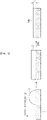
- FIG. 1 shows a process of applying insulation coating liquid on the end of a positive electrode mixture coated portion in order to prevent a short circuit of a positive electrode and a negative electrode.
- an electrode mixture layer 12 is formed by coating an electrode slurry including an electrode active material on an electrode current collector 11, and insulation coating liquid is applied on the non-coated part around the end of the electrode mixture layer 12 and is dried to thereby form insulation coating layers 13a and 13b. Since the electrode mixture layer before being dried has fluidity, a sliding phenomenon, in which the thickness of the end gradually decreases, is shown. Further, since the insulation coating liquid is fluid, the insulation coating liquid is coated not only on the non-coated part, but also on the sliding portion of the electrode mixture layer. Hence, the finally formed insulation coating layer includes a pure insulation coating layer 13b formed on the non-coated part and an overlay part insulation coating layer 13a formed on the electrode mixture layer.
- the pure insulation coating layer blocks movement of electrons to thereby prevent a short circuit of the positive electrode and the negative electrode, and the overlay part insulation coating layer limits the movement of lithium ions to a non-existing place to thereby further improve safety of the battery.
- the insulation of the insulation coating layer is proportional to the thickness of the insulation coating layer, the insulating performance is managed by measuring the thickness of the insulation coating layer.
- the thickness of the coated pure insulation coating layer 13b can be easily measured, but in order to separately measure the thickness of the insulation coating layer 13a of the overlay part, new equipment should be introduced, which may take a lot of time and costs.
- part of the insulation coating liquid is permeated into pores of the electrode mixture layer unlike the pure insulation coating layer, and accordingly, the insulating performance of the overlay part is shown by the action of both the insulating material of the insulation coating layer and the insulating material permeated into the electrode mixture layer. Hence, it is difficult to evaluate insulation by measuring the thickness of the insulation coating layer of the overlay part.
- an aspect of the present invention provides a method of evaluating insulation of an insulation coating layer in an overlay part without introduction of new equipment.
- a method of evaluating insulation of the present invention for solving the above problems includes:
- the process (c) includes:
- the process (a) includes:
- the process (b) includes:
- the process (c-2) includes:
- the process (a-3) includes a process of manufacturing a coin cell including the simulated overlay part, and measuring capacity f of the overlay part by measuring a charge capacity or a discharge capacity of the coin cell, and the coin cell may be a half cell.
- part of the insulation coating liquid applied on the electrode mixture layer is permeated into the electrode mixture layer during the simulating of the overlay part of the process (a).
- the thickness d which has been increased by insulation coating is obtained by subtracting a thickness of the electrode mixture layer before application of the insulation coating liquid from a total thickness of the electrode mixture layer and the insulation coating layer after drying the insulation coating liquid.
- the insulation coating layer includes polyvinylidene fluoride (PVDF).
- PVDF polyvinylidene fluoride
- the electrode is a positive electrode.
- the thickness of the pure insulation coating layer is equal to or less than 15 ⁇ m.
- the present invention it is possible to evaluate the insulation of the overlay part by measuring the thickness of the pure insulation coating layer of which the thickness can be easily measured, and the insulation evaluation result is also relatively accurate by reflecting the insulating performance by insulating materials permeated into the electrode mixture layer in the overlay part.
- the overlay part means a partial electrode portion where an insulation coating layer has been formed on an electrode mixture layer in an electrode including an insulation coating layer.
- the present invention relates to a method of evaluating insulation in an overlay part where an insulation coating layer has been laminated on a sliding portion of an electrode mixture layer, and more specifically to a new method of evaluating insulation in an overlay part by measuring the thickness of an insulation coating layer coated on a non-coated part (hereinafter, referred to as "pure insulation coating layer") because it is difficult to measure the thickness of the insulation coating layer in the overlay part.
- the sliding portion has a concept of including an inclined region of the end of the electrode mixture layer, and its periphery, which are formed by fluidity of the electrode slurry.
- the insulating material may be at least one selected from the group consisting of polybutadiene, polyurethane, polyimide, acetate, polyester, polyphenylene sulfide (PPS), polyphenylene, styrene-butadiene-based copolymer, (meta)acrylic acid copolymer, (meta)acrylate copolymer, polyacrylonitrile, polyvinyl chloride, polyfluoro compound, polyvinyl alcohol, and polycyanoacrylate.
- PPS polyphenylene sulfide
- PVDF polyvinylidene fluoride
- the insulation coating layer may be formed on the regions including from the end of the electrode mixture layer to the active material non-coated part and may be formed to have a thickness equal to or less than 15 ⁇ m and specifically in the range of 2 to 15 ⁇ m.
- the thickness of the insulation coating layer is less than 2 ⁇ m, the effects of preventing deintercalation of active materials or suppressing the movement of lithium ions become insignificant, and when the thickness of the insulation coating layer exceeds 15 ⁇ m, a crack may be generated on the active material layer due to a step difference of the thickness.
- the insulation coating layer generally forms a positive electrode, and the method of evaluating insulation of the present invention may be applied to a positive electrode.
- FIG. 2 is a flowchart illustrating the flow of a method of evaluating insulation of an overlay part according to an embodiment of the present invention.
- a method for evaluating insulation of an overlay part according to the present invention includes:
- FIG. 3 is a flowchart illustrating a process of deriving relation formula 1 of process (c) according to an embodiment of the present invention.
- the process of deriving relation formula 1 includes:
- the overlay part simulation process of the process (a) and the pure insulation coating layer simulation process of the process (b) are performed, and data, which are necessary to derive the relation formula 2 and relation formula 3, is collected through the two simulation processes.
- the thickness of the insulation coating layer is not measured, and the insulation in the overlay part is evaluated by measuring the thickness of the pure insulation coating layer.
- two simulation processes of simulating the overlay part and simulating the pure insulation coating layer are performed. Hence, the process (a) of simulating the overlay part will be described, and the process (b) of simulating the pure insulation coating layer will then be described.
- FIG. 4 is a schematic diagram illustrating a process of simulating the overlay part of the process (a).
- an electrode slurry including the electrode active material is coated on the current collector 11, and insulation coating liquid S is then coated on the electrode mixture layer 12.
- the gap c of the applicator, which applies the insulation coating liquid is measured, and the measurement values are saved as c 1 , c 2 , c 3 , c 4.... c n .
- the overlay part is simulated as an insulation coating layer 13a is formed on the electrode mixture layer.
- the coating thickness of the insulation coating liquid before the drying process is I and the thickness decreases and becomes e after the drying process. This occurs as the solvent of the insulation coating liquid is removed and part of the insulation coating liquid elements is permeated into pores of the electrode mixture layer. As such, the insulation in the overlay part is shown by the insulation coating liquid elements existing in the electrode mixture layer together with the insulation coating layer which is distinguished with the naked eye.
- the thickness of the electrode mixture layer slightly increases, which is due to the insulation coating elements existing in the electrode mixture layer.
- both the increase in the thickness of the electrode mixture layer and the thickness e of the final insulation coating layer show insulation, and accordingly, the process of collecting data about the thickness d which has been increased by insulation coating is included.
- the thickness d which has been increased by insulation coating is obtained by subtracting a thickness of the electrode mixture layer before application of the insulation coating liquid from a total thickness of the electrode mixture layer and the insulation coating layer after drying the insulation coating liquid.
- the overlay part is simulated, and the thickness d, which has been increased by insulation coating, is considered as a portion which shows insulation by insulation coating, and the process of measuring the thickness d and the capacity f of the overlay part is performed.
- the capacity f is measured to measure the insulation.
- FIG. 6 is a flowchart illustrating a detailed process of process (a) according to an embodiment of the present invention.
- the process (a) according to one embodiment of the present invention includes:
- the process (a-3) includes a process of manufacturing a coin cell including the simulated overlay part, and measuring capacity f of the overlay part by measuring a charge capacity or a discharge capacity of the coin cell.
- the coin cell may be a half cell.
- FIG. 5 is a schematic diagram illustrating a process of simulating a pure insulation coating layer of process (b) and collecting data according to an embodiment of the present invention.
- a pure insulation coating layer 13b is simulated by applying insulation coating liquid S on the current collector 11 and drying the insulation coating liquid S.
- FIG. 7 is a flowchart illustrating a detailed process of process (b) according to an embodiment of the present invention.
- the process (b) according to one embodiment of the present invention includes:
- the data which is collected by repeating the processes (b-1) to (b-2), is used as reference data when generating relation formula 5 to be described later.
- the process (c-1) of the present invention is a process of deriving relation formula 2 between the thickness D which has been increased by insulation coating and the capacity F of the overlay part. This is generated based on the thickness d which has been increased by insulation coating and its corresponding capacity f of the overlay part, collected in the process (a). Namely, relation formula 2 is derived through the analysis on the correlation between the d and the capacity f corresponding thereto.
- FIG. 8 is a flowchart illustrating a detailed process for deriving relation formula 3 of process (c-2) according to an embodiment of the present invention.
- the process (c-2) of deriving relation formula 3 of the present invention includes:
- relation formula 4 of the (c-2-1) is generated from the data about the length c of the gap of the applicator, which is collected during the process (a), and the data about the thickness d, which has been increased by insulation coating, according thereto. Namely, relation formula 4 is derived through the analysis on the correlation between the c and the d corresponding thereto.
- relation formula 5 of the (c-2-2) is generated from the data about the length g of the gap of the applicator, which is collected during the process (b), and the data about the thickness d of the pure insulation coating layer according thereto. Namely, relation formula 5 is derived through the analysis on the correlation between the g and the h corresponding thereto.
- the process of generating relation formula 3 of the (c-2-3) is a process of deriving relation formula 3 between thickness D which has been increased by insulation coating and thickness H of the pure insulation coating layer by combining the above-generated relation formula 4 and relation formula 5 and eliminating the length c and g of the gap of the applicator, which is the common parameter of these formulas.
- relation formula 2 is a relation formula between the thickness D which has been increased by insulation coating and the capacity F of the overlay part
- relation formula 3 is a relation formula between the thickness D which has been increased by insulation coating and the thickness H of the pure insulation coating layer.
- the capacity F of the overlay part can be calculated by measuring the thickness of the pure insulation coating layer and substituting the measured thickness of the pure insulation coating layer into the relation formula 1, and the insulation can be evaluated through the capacity F. Hence, it is possible to easily evaluate the insulation of the overlay part, and the insulation evaluated like this can be guaranteed.
- a positive electrode slurry was manufactured by mixing a positive electrode active material, which contains nickel, manganese and chrome at the ratio of 7: 1: 2, carbon black as a conductive material, and SBR as a binder, at the weight ratio of 97: 1.5 and 1.5, and dispersing the mixture in an NMP solvent.
- An electrode mixture layer was manufactured by applying the positive electrode slurry on an aluminum current collector and drying the positive electrode slurry. Thereafter, the simulation of the overlay part was completed by applying insulation coating liquid of 10 ⁇ m or less including PVDF and drying the insulation coating liquid at a temperature of 130°C for 20 minutes.
- Insulation coating liquid was applied on an aluminum current collector while adjusting the length g of the gap of the applicator using the aluminum current collector and the insulation coating liquid which are the same as in the simulation of the overlay part, and the applied insulation coating liquid was dried at 130°C for 20 minutes to thereby simulate a pure insulation coating layer.
- the relation formula 2 between the thickness D which has been increased by insulation coating, and the capacity F of the overlay part was generated from data d and f collected during the process (a), and the generated relation formula 2 is as follows.
- the relation formula 3 was derived by performing the process (c-2-1) of deriving relation formula 4 between the gap C of the applicator and the thickness D which has been increased by insulation coating, and the process (c-2-2) of deriving the relation formula 5 between the length G of the gap of the applicator and the thickness H of the pure insulation coating layer.
- the relation formula 4 is derived through the analysis of data c and d collected during the process (a), and the derived relation formula 4 is shown in FIG. 9 and is as follows.
- D 0.0566 C ⁇ 1.2553
- the relation formula 3 between thickness D which has been increased by insulation coating and thickness H of the pure insulation coating layer is derived by the combination of the derived relation formula 4 and relation formula 5.
- both C and G are the length of the gap of the applicator of the insulation coating liquid.
- the insulation of the overlay part can be evaluated by measuring the thickness of the pure insulation coating layer and substituting the measured thickness into the relation formula 1.
Landscapes
- Chemical & Material Sciences (AREA)
- Chemical Kinetics & Catalysis (AREA)
- Electrochemistry (AREA)
- General Chemical & Material Sciences (AREA)
- Engineering & Computer Science (AREA)
- Manufacturing & Machinery (AREA)
- General Physics & Mathematics (AREA)
- Physics & Mathematics (AREA)
- Materials Engineering (AREA)
- Battery Electrode And Active Subsutance (AREA)
- Investigating Or Analyzing Materials By The Use Of Electric Means (AREA)
- Application Of Or Painting With Fluid Materials (AREA)
- Secondary Cells (AREA)
Abstract
Description
- This application claims the benefit of priority based on
Korean Patent Application No. 10-2020-0153807, filed on November 17, 2020 - The present invention relates to a method of evaluating insulation of an insulation coating layer, and specifically to a method of evaluating insulation of an overlay part without measuring the thickness of an insulation coating layer in an overlay part where the insulation coating layer has been laminated on an electrode mixture layer.
- As technology development and demand for mobile devices increase, the demand for batteries as an energy source is rapidly increasing, and among such secondary batteries, many studies have been conducted on lithium secondary batteries having a high energy density and a discharge voltage, and have been commercialized and widely used.
- When such a lithium secondary battery is exposed to a high temperature, there is a possibility that a short circuit occurs due to a contact between the positive electrode and the negative electrode. Further, even when a large electric current flows within a short period of time by overcharge, an external short circuit, nail penetration, a local crush, etc., there is a danger of ignition/explosion as the battery is heated by heat generation.
- Such a phenomenon usually occurs at the end of the electrode active material applied on the electrode current collector at the time of electrode lamination, and various methods to reduce the possibility of a short circuit of an electrode at an external shock or high temperature have been tried.
-
FIG. 1 shows a process of applying insulation coating liquid on the end of a positive electrode mixture coated portion in order to prevent a short circuit of a positive electrode and a negative electrode. Referring toFIG. 1 , anelectrode mixture layer 12 is formed by coating an electrode slurry including an electrode active material on anelectrode current collector 11, and insulation coating liquid is applied on the non-coated part around the end of theelectrode mixture layer 12 and is dried to thereby forminsulation coating layers insulation coating layer 13b formed on the non-coated part and an overlay partinsulation coating layer 13a formed on the electrode mixture layer. - In the electrode as shown in
FIG. 1 , the pure insulation coating layer blocks movement of electrons to thereby prevent a short circuit of the positive electrode and the negative electrode, and the overlay part insulation coating layer limits the movement of lithium ions to a non-existing place to thereby further improve safety of the battery. - Further, since the insulation of the insulation coating layer is proportional to the thickness of the insulation coating layer, the insulating performance is managed by measuring the thickness of the insulation coating layer. In an electrode having an overlay part, the thickness of the coated pure
insulation coating layer 13b can be easily measured, but in order to separately measure the thickness of theinsulation coating layer 13a of the overlay part, new equipment should be introduced, which may take a lot of time and costs. Further, in the insulation coating layer of the overlay part, part of the insulation coating liquid is permeated into pores of the electrode mixture layer unlike the pure insulation coating layer, and accordingly, the insulating performance of the overlay part is shown by the action of both the insulating material of the insulation coating layer and the insulating material permeated into the electrode mixture layer. Hence, it is difficult to evaluate insulation by measuring the thickness of the insulation coating layer of the overlay part. - As such, there is a need for a technology for predicting insulation of an overlay part using conventional management factors without introducing new equipment.
- The present invention is believed to solve at least some of the above problems. For example, an aspect of the present invention provides a method of evaluating insulation of an insulation coating layer in an overlay part without introduction of new equipment.
- A method of evaluating insulation of the present invention for solving the above problems includes:
- (a) a process of applying and drying insulation coating liquid on the electrode mixture layer to thereby simulate the overlay part, and collecting data about a length c of a gap of an applicator, a thickness d which has been increased by insulation coating, and a capacity f of the overlay part;
- (b) a process of applying and drying insulation coating liquid on a current collector to thereby simulate a pure insulation coating layer, and collecting data about a length g of a gap of an applicator and a thickness h of the pure insulation coating layer;
- (c) a process of generating a
relation formula 1 between thickness H of the pure insulation coating layer and capacity F of the overlay part based on data collected through the processes (a) and (b); - (d) a process of measuring a thickness of a pure insulation coating layer at an electrode for evaluation; and
- (e) a process of calculating the capacity of the overlay part by substituting the thickness of the pure insulation coating layer measured in the process (d) into the
relation formula 1. - In one specific example, the process (c) includes:
- (c-1) a process of deriving
relation formula 2 between thickness D which has been increased by insulation coating and capacity F of the overlay part based on data about the capacity f of the overlay part according to the thickness d which has been increased by insulation coating, which has been collected during the process (a); - (c-2) a process of deriving
relation formula 3 between the thickness D which has been increased by insulation coating and the thickness H of the pure insulation coating layer, based on data about the length c of the gap of the applicator and the thickness d which has been increased by insulation coating, collected during the process (a), and data about the length g of the gap of the applicator and the thickness h of the pure insulation coating layer, collected during the process (b); and - (c-3) a process of deriving the
relation formula 1 by combination of therelation formula 2 and therelation formula 3. - In one specific example, the process (a) includes:
- (a-1) a process of applying and drying insulation coating liquid on the electrode mixture layer to thereby simulate the overlay part, and measuring a length c of the gap of the applicator which applies the insulation coating liquid;
- (a-2) a process of measuring the thickness d which has been increased by insulation coating in the simulated overlay part; and
- (a-3) a process of measuring capacity f of the simulated overlay part.
- Herein, data about the length c of the gap of the applicator, the thickness d which has been increased by insulation coating, and the capacity f of the overlay part is collected by repeating the processes (a-1) to (a-3).
- In one specific example, the process (b) includes:
- (b-1) a process of applying and drying insulation coating liquid on the current collector to thereby simulate the pure insulation coating layer, and measuring a length g of the gap of the applicator which applies the insulation coating liquid; and
- (b-2) a process of measuring thickness h of the pure insulation coating layer simulated by the process (b-1).
- Herein, data about the length g of the gap of the applicator which applies the insulation coating liquid, and the thickness h of the pure insulation coating layer is collected by repeating the processes (b-1) to (b-2).
- In one specific example, the process (c-2) includes:
- (c-2-1) a process of deriving
relation formula 4 between length C of the gap of the applicator and thickness D which has been increased by insulation coating based on data about the length c of the gap of the applicator and the thickness d which has been increased by insulation coating, collected during the process (a); - (c-2-2) a process of deriving
relation formula 5 between length G of the gap of the applicator and thickness H of the pure insulation coating layer, based on data about the length g of the gap of the applicator and the thickness h of the pure insulation coating layer, collected during the process (b); and - (c-2-3) a process of deriving
relation formula 3 between thickness D which has been increased by insulation coating and thickness H of the pure insulation coating layer by eliminating a gap of the applicator, which is a parameter, by combination of therelation formula 4 and therelation formula 5. - In one specific example, the process (a-3) includes a process of manufacturing a coin cell including the simulated overlay part, and measuring capacity f of the overlay part by measuring a charge capacity or a discharge capacity of the coin cell, and the coin cell may be a half cell.
- In one specific example, part of the insulation coating liquid applied on the electrode mixture layer is permeated into the electrode mixture layer during the simulating of the overlay part of the process (a).
- In one specific example, the thickness d which has been increased by insulation coating is obtained by subtracting a thickness of the electrode mixture layer before application of the insulation coating liquid from a total thickness of the electrode mixture layer and the insulation coating layer after drying the insulation coating liquid.
- In one specific example, the insulation coating layer includes polyvinylidene fluoride (PVDF).
- In one specific example, the electrode is a positive electrode.
- In one specific example, the thickness of the pure insulation coating layer is equal to or less than 15 µm.
- According to the present invention, it is possible to evaluate the insulation of the overlay part by measuring the thickness of the pure insulation coating layer of which the thickness can be easily measured, and the insulation evaluation result is also relatively accurate by reflecting the insulating performance by insulating materials permeated into the electrode mixture layer in the overlay part.
-
-
FIG. 1 is a schematic diagram showing a process of applying an insulation coating liquid to the end of a positive electrode mixture coated portion. -
FIG. 2 is a flowchart illustrating the flow of a method of evaluating insulation of an overlay part according to an embodiment of the present invention. -
FIG. 3 is a flowchart illustrating a process of derivingrelation formula 1 of process (c) according to an embodiment of the present invention. -
FIG. 4 is a schematic diagram illustrating a process of process (a) of simulating an overlay part and collecting data according to an embodiment of the present invention. -
FIG. 5 is a schematic diagram illustrating a process of process (b) of simulating a pure insulation coating layer and collecting data according to an embodiment of the present invention. -
FIG. 6 is a flowchart illustrating a detailed process of process (a) according to an embodiment of the present invention. -
FIG. 7 is a flowchart illustrating a detailed process of process (b) according to an embodiment of the present invention. -
FIG. 8 is a flowchart illustrating a detailed process for derivingrelation formula 3 of process (c-2) according to an embodiment of the present invention. -
FIG. 9 is a graph showingrelation formula 4 andrelation formula 5 according to an embodiment of the present invention. - Hereinafter, the present invention will be described in detail with reference to the drawings. The terms and words used in the present specification and claims should not be construed as limited to ordinary or dictionary terms and the inventor may properly define the concept of the terms in order to best describe its invention. The terms and words should be construed as meaning and concept consistent with the technical idea of the present invention.
- In this application, it should be understood that terms such as "include" or "have" are intended to indicate that there is a feature, number, step, operation, component, part, or a combination thereof described on the specification, and they do not exclude in advance the possibility of the presence or addition of one or more other features or numbers, steps, operations, components, parts or combinations thereof. Also, when a portion such as a layer, a film, an area, a plate, etc. is referred to as being "on" another portion, this includes not only the case where the portion is "directly on" the another portion but also the case where further another portion is interposed therebetween. On the other hand, when a portion such as a layer, a film, an area, a plate, etc. is referred to as being "under" another portion, this includes not only the case where the portion is "directly under" the another portion but also the case where further another portion is interposed therebetween. In addition, to be disposed "on" in the present application may include the case disposed at the bottom as well as the top.
- Further, in the present invention, the overlay part means a partial electrode portion where an insulation coating layer has been formed on an electrode mixture layer in an electrode including an insulation coating layer.
- Hereinafter, the present invention will be described in detail with reference to the drawings.
- The present invention relates to a method of evaluating insulation in an overlay part where an insulation coating layer has been laminated on a sliding portion of an electrode mixture layer, and more specifically to a new method of evaluating insulation in an overlay part by measuring the thickness of an insulation coating layer coated on a non-coated part (hereinafter, referred to as "pure insulation coating layer") because it is difficult to measure the thickness of the insulation coating layer in the overlay part.
- In the specification of the present invention, the sliding portion has a concept of including an inclined region of the end of the electrode mixture layer, and its periphery, which are formed by fluidity of the electrode slurry.
- In the present invention, there is no limitation to the type of the insulating material included in the insulation coating liquid for forming an insulation coating layer as long as it exhibits insulating effects. The insulating material may be at least one selected from the group consisting of polybutadiene, polyurethane, polyimide, acetate, polyester, polyphenylene sulfide (PPS), polyphenylene, styrene-butadiene-based copolymer, (meta)acrylic acid copolymer, (meta)acrylate copolymer, polyacrylonitrile, polyvinyl chloride, polyfluoro compound, polyvinyl alcohol, and polycyanoacrylate. In the example of the present invention, polyvinylidene fluoride (PVDF) included in the insulating material.
- The insulation coating layer may be formed on the regions including from the end of the electrode mixture layer to the active material non-coated part and may be formed to have a thickness equal to or less than 15 µm and specifically in the range of 2 to 15 µm. When the thickness of the insulation coating layer is less than 2 µm, the effects of preventing deintercalation of active materials or suppressing the movement of lithium ions become insignificant, and when the thickness of the insulation coating layer exceeds 15 µm, a crack may be generated on the active material layer due to a step difference of the thickness.
- The insulation coating layer generally forms a positive electrode, and the method of evaluating insulation of the present invention may be applied to a positive electrode.
-
FIG. 2 is a flowchart illustrating the flow of a method of evaluating insulation of an overlay part according to an embodiment of the present invention. Referring toFIG. 2 , a method for evaluating insulation of an overlay part according to the present invention includes: - (a) a process of applying and drying insulation coating liquid on the electrode mixture layer to thereby simulate the overlay part, and collecting data about a length c of a gap of an applicator, a thickness d which has been increased by insulation coating, and a capacity f of the overlay part;
- (b) a process of applying and drying insulation coating liquid on a current collector to thereby simulate a pure insulation coating layer, and collecting data about a length g of a gap of an applicator and a thickness h of the pure insulation coating layer;
- (c) a process of generating a
relation formula 1 between thickness H of the pure insulation coating layer and capacity F of the overlay part based on data collected through the processes (a) and (b); - (d) a process of measuring a thickness of a pure insulation coating layer at an electrode for evaluation; and
- (e) a process of calculating the capacity of the overlay part by substituting the thickness of the pure insulation coating layer measured in the process (d) into the
relation formula 1. - Likewise, according to the present invention, it is possible to evaluate insulation of the overlay part by measuring the thickness of the pure insulation coating layer and substituting the thickness of the measured pure insulation coating layer into
relation formula 1. Hence, introduction of new equipment is not necessary in order to measure the thickness of the insulation coating layer in the overlay part, and there is no error at the time of measuring the thickness of the insulation coating layer in the overlay part. - Hereinafter, the process of deriving the
relation formula 1 will be described in detail. -
FIG. 3 is a flowchart illustrating a process of derivingrelation formula 1 of process (c) according to an embodiment of the present invention. Referring toFIG. 3 , the process of derivingrelation formula 1 includes: - (c-1) a process of deriving
relation formula 2 between thickness D which has been increased by insulation coating and capacity F of the overlay part based on data about the capacity f of the overlay part according to the thickness d which has been increased by insulation coating, which has been collected during the process (a); - (c-2) a process of deriving
relation formula 3 between the thickness D which has been increased by insulation coating and the thickness H of the pure insulation coating layer, based on data about the length c of the gap of the applicator and the thickness d which has been increased by insulation coating, collected during the process (a), and data about the length g of the gap of the applicator and the thickness h of the pure insulation coating layer, collected during the process (b); and - (c-3) a process of deriving the
relation formula 1 by combination of therelation formula 2 and therelation formula 3. - In the present invention, in order to derive
relation formula 2 between the thickness D which has been increased by insulation coating in the overlay part and the capacity F of the overlay part, andrelation formula 3 between the thickness D which has been increased by insulation coating in the overlay part and the thickness H of the pure insulation coating layer, the overlay part simulation process of the process (a) and the pure insulation coating layer simulation process of the process (b) are performed, and data, which are necessary to derive therelation formula 2 andrelation formula 3, is collected through the two simulation processes. - Hereinafter, the process of deriving the
relation formula 2 andrelation formula 3 through two simulation processes will be described. - In the present invention, in order to evaluate insulation in the overlay part, the thickness of the insulation coating layer is not measured, and the insulation in the overlay part is evaluated by measuring the thickness of the pure insulation coating layer. As such, in the present invention, two simulation processes of simulating the overlay part and simulating the pure insulation coating layer are performed. Hence, the process (a) of simulating the overlay part will be described, and the process (b) of simulating the pure insulation coating layer will then be described.
-
FIG. 4 is a schematic diagram illustrating a process of simulating the overlay part of the process (a). Referring toFIG. 4 , an electrode slurry including the electrode active material is coated on thecurrent collector 11, and insulation coating liquid S is then coated on theelectrode mixture layer 12. At this time, the gap c of the applicator, which applies the insulation coating liquid, is measured, and the measurement values are saved as c1, c2, c3, c4....cn. Thereafter, if the drying process is performed, the overlay part is simulated as aninsulation coating layer 13a is formed on the electrode mixture layer. - As described above, in the overlay part of the electrode, part of the elements of the insulation coating liquid are permeated into pores of the electrode mixture layer. As such, the insulation of the overlay part is shown by the insulation coating liquid permeated into the electrode mixture layer, too. Hence, in order to guarantee the reliability, data, which is obtained by simulating the overlay part, is necessary.
- Referring to
FIG. 4 , the coating thickness of the insulation coating liquid before the drying process is I and the thickness decreases and becomes e after the drying process. This occurs as the solvent of the insulation coating liquid is removed and part of the insulation coating liquid elements is permeated into pores of the electrode mixture layer. As such, the insulation in the overlay part is shown by the insulation coating liquid elements existing in the electrode mixture layer together with the insulation coating layer which is distinguished with the naked eye. - Referring to
FIG. 4 , after applying and drying the insulation coating liquid, the thickness of the electrode mixture layer slightly increases, which is due to the insulation coating elements existing in the electrode mixture layer. Hence, in the present invention, in the simulated overlay part, after the drying of the insulation coating liquid, both the increase in the thickness of the electrode mixture layer and the thickness e of the final insulation coating layer show insulation, and accordingly, the process of collecting data about the thickness d which has been increased by insulation coating is included. - The thickness d which has been increased by insulation coating is obtained by subtracting a thickness of the electrode mixture layer before application of the insulation coating liquid from a total thickness of the electrode mixture layer and the insulation coating layer after drying the insulation coating liquid.
- Likewise, in the process (a) of the present invention, the overlay part is simulated, and the thickness d, which has been increased by insulation coating, is considered as a portion which shows insulation by insulation coating, and the process of measuring the thickness d and the capacity f of the overlay part is performed. The capacity f is measured to measure the insulation.
-
FIG. 6 is a flowchart illustrating a detailed process of process (a) according to an embodiment of the present invention. Referring toFIG. 6 , the process (a) according to one embodiment of the present invention includes: - (a-1) a process of applying and drying insulation coating liquid on the electrode mixture layer to thereby simulate the overlay part, and measuring a length c of the gap of the applicator which applies the insulation coating liquid;
- (a-2) a process of measuring the thickness d which has been increased by insulation coating in the simulated overlay part; and
- (a-3) a process of measuring capacity f of the simulated overlay part.
- Herein, data about the length c of the gap of the applicator, the thickness d which has been increased by insulation coating, and the capacity f of the overlay part is collected by repeating the processes (a-1) to (a-3).
- In the process (a-1), data of c1, c2, c3, c4...cn is collected by measuring the gap c of the applicator, and in the process (a-2), data of d1, d2, d3, d4...dn is collected by measuring the thickness d which has been increased by insulation coating, and in the process (a-3), data of f1, f2, f3, f4...fn is collected by measuring the capacity f of the overlay part.
- In an embodiment of the present invention, the process (a-3) includes a process of manufacturing a coin cell including the simulated overlay part, and measuring capacity f of the overlay part by measuring a charge capacity or a discharge capacity of the coin cell. At this time, the coin cell may be a half cell.
- The data, which is collected by repeating the processes (a-1) to (a-3), is used as reference data when generating
relation formula 2 andrelation formula 4. -
FIG. 5 is a schematic diagram illustrating a process of simulating a pure insulation coating layer of process (b) and collecting data according to an embodiment of the present invention. Referring toFIG. 5 , a pureinsulation coating layer 13b is simulated by applying insulation coating liquid S on thecurrent collector 11 and drying the insulation coating liquid S. -
FIG. 7 is a flowchart illustrating a detailed process of process (b) according to an embodiment of the present invention. Referring toFIG. 7 , the process (b) according to one embodiment of the present invention includes: - (b-1) a process of applying and drying insulation coating liquid on the current collector to thereby simulate the pure insulation coating layer, and measuring a length g of the gap of the applicator which applies the insulation coating liquid; and
- (b-2) a process of measuring thickness h of the pure insulation coating layer simulated by the process (b-1).
- Herein, data about the length g of the gap of the applicator which applies the insulation coating liquid, and the thickness h of the pure insulation coating layer is collected by repeating the processes (b-1) to (b-2).
- In the process (b-1), data of g1, g2, g3, g4...gn is collected by measuring the length g of the gap of the applicator which applies insulation coating liquid, and in the process (b-2), data of h1, h2, h3, h4...hn is collected by measuring the thickness h of the pure insulation coating layer corresponding to the g.
- The data, which is collected by repeating the processes (b-1) to (b-2), is used as reference data when generating
relation formula 5 to be described later. - The process (c-1) of the present invention is a process of deriving
relation formula 2 between the thickness D which has been increased by insulation coating and the capacity F of the overlay part. This is generated based on the thickness d which has been increased by insulation coating and its corresponding capacity f of the overlay part, collected in the process (a). Namely,relation formula 2 is derived through the analysis on the correlation between the d and the capacity f corresponding thereto. -
FIG. 8 is a flowchart illustrating a detailed process for derivingrelation formula 3 of process (c-2) according to an embodiment of the present invention. Referring toFIG. 8 , the process (c-2) of derivingrelation formula 3 of the present invention includes: - (c-2-1) a process of deriving
relation formula 4 between length C of the gap of the applicator and thickness D which has been increased by insulation coating based on data about the length c of the gap of the applicator and the thickness d which has been increased by insulation coating, collected during the process (a); - (c-2-2) a process of deriving
relation formula 5 between length G of the gap of the applicator and thickness H of the pure insulation coating layer, based on data about the length g of the gap of the applicator and the thickness h of the pure insulation coating layer, collected during the process (b); and - (c-2-3) a process of deriving
relation formula 3 between thickness D which has been increased by insulation coating and thickness H of the pure insulation coating layer by eliminating a gap of the applicator, which is a parameter, by combination of therelation formula 4 and therelation formula 5. - The
relation formula 4 of the (c-2-1) is generated from the data about the length c of the gap of the applicator, which is collected during the process (a), and the data about the thickness d, which has been increased by insulation coating, according thereto. Namely,relation formula 4 is derived through the analysis on the correlation between the c and the d corresponding thereto. - The
relation formula 5 of the (c-2-2) is generated from the data about the length g of the gap of the applicator, which is collected during the process (b), and the data about the thickness d of the pure insulation coating layer according thereto. Namely,relation formula 5 is derived through the analysis on the correlation between the g and the h corresponding thereto. - The process of generating
relation formula 3 of the (c-2-3) is a process of derivingrelation formula 3 between thickness D which has been increased by insulation coating and thickness H of the pure insulation coating layer by combining the above-generatedrelation formula 4 andrelation formula 5 and eliminating the length c and g of the gap of the applicator, which is the common parameter of these formulas. - The above-described
relation formula 2 is a relation formula between the thickness D which has been increased by insulation coating and the capacity F of the overlay part, and therelation formula 3 is a relation formula between the thickness D which has been increased by insulation coating and the thickness H of the pure insulation coating layer. When combining these two formulas, the common parameter D can be eliminated. As such,relation formula 1 between the thickness H of the pure insulation coating layer and the capacity F of the overlay part is generated. - In the evaluation method of the present invention, when evaluating insulation of an overlay part in an electrode including an overlay part, the capacity F of the overlay part can be calculated by measuring the thickness of the pure insulation coating layer and substituting the measured thickness of the pure insulation coating layer into the
relation formula 1, and the insulation can be evaluated through the capacity F. Hence, it is possible to easily evaluate the insulation of the overlay part, and the insulation evaluated like this can be guaranteed. - Hereinafter, embodiments of the present invention are described, but the following embodiments are used to illustrate the invention, and the category of the present invention is not limited to these alone.
- A positive electrode slurry was manufactured by mixing a positive electrode active material, which contains nickel, manganese and chrome at the ratio of 7: 1: 2, carbon black as a conductive material, and SBR as a binder, at the weight ratio of 97: 1.5 and 1.5, and dispersing the mixture in an NMP solvent. An electrode mixture layer was manufactured by applying the positive electrode slurry on an aluminum current collector and drying the positive electrode slurry. Thereafter, the simulation of the overlay part was completed by applying insulation coating liquid of 10 µm or less including PVDF and drying the insulation coating liquid at a temperature of 130°C for 20 minutes.
- At this time, data was collected by measuring the length c of the gap of the applicator which applies insulation coating liquid, the thickness d which has been increased by insulation coating corresponding thereto, and the capacity f of the overlay part, and then repeating the process while changing the c.
- When measuring the capacity f, a coin-half cell was manufactured using the positive electrode including the simulated overlay part, and the counter electrode of lithium, and charge/discharge was performed, and discharge capacity f was then measured.
- Insulation coating liquid was applied on an aluminum current collector while adjusting the length g of the gap of the applicator using the aluminum current collector and the insulation coating liquid which are the same as in the simulation of the overlay part, and the applied insulation coating liquid was dried at 130°C for 20 minutes to thereby simulate a pure insulation coating layer.
- At this time, data was collected by measuring the length g of the gap of the applicator which applies insulation coating liquid and the thickness h of the pure insulation coating layer, and then repeating the process while changing the g.
- The
relation formula 2 between the thickness D which has been increased by insulation coating, and the capacity F of the overlay part was generated from data d and f collected during the process (a), and the generatedrelation formula 2 is as follows. - The derived
relation formula 2 is as follows.
- The
relation formula 3 was derived by performing the process (c-2-1) of derivingrelation formula 4 between the gap C of the applicator and the thickness D which has been increased by insulation coating, and the process (c-2-2) of deriving therelation formula 5 between the length G of the gap of the applicator and the thickness H of the pure insulation coating layer. - The
relation formula 4 is derived through the analysis of data c and d collected during the process (a), and the derivedrelation formula 4 is shown inFIG. 9 and is as follows.
- The
relation formula 5 is derived through the analysis of data g and h collected during the process (b), and the derivedrelation formula 5 is shown inFIG. 9 and is as follows.
- The
relation formula 3 between thickness D which has been increased by insulation coating and thickness H of the pure insulation coating layer is derived by the combination of the derivedrelation formula 4 andrelation formula 5. Specifically, in the derived relation formula 4 (D=0.0566C-1.2553) and relation formula 5 (H=0.0417G-1.5335), both C and G are the length of the gap of the applicator of the insulation coating liquid. As such, therelation formula 3 between the thickness H of the pure insulation coating layer and the thickness D which has been increased by insulation coating is derived using C and G as parameters, and therelation formula 3 is as follows.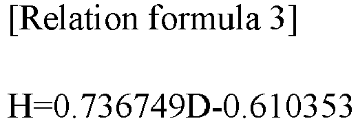
- The
relation formula 1 between the thickness H of the pure insulation coating layer and the capacity F of the overlay part may be obtained by combination of therelation formula 3 and therelation formula 2. Specifically, therelation formula 1 is obtained as common parameter D is eliminated by combination ofrelation formula 3 andrelation formula 2, and therelation formula 1 is as follows.
- The insulation of the overlay part can be evaluated by measuring the thickness of the pure insulation coating layer and substituting the measured thickness into the
relation formula 1. -
- 11: current collector
- 12: electrode mixture layer
- 13: insulation coating layer
- 13a: insulation coating layer of overlay part
- 13b: pure insulation coating layer
- S: insulation coating liquid
Claims (12)
- A method for evaluating insulation of an overlay part where an insulation coating layer has been laminated on a sliding portion of an electrode mixture layer, the method comprising:(a) a process of applying and drying insulation coating liquid on the electrode mixture layer to thereby simulate the overlay part, and collecting data about a length c of a gap of an applicator, a thickness d which has been increased by insulation coating, and a capacity f of the overlay part;(b) a process of applying and drying insulation coating liquid on a current collector to thereby simulate a pure insulation coating layer, and collecting data about a length g of a gap of an applicator and a thickness h of the pure insulation coating layer;(c) a process of generating a relation formula 1 between thickness H of the pure insulation coating layer and capacity F of the overlay part based on data collected through the processes (a) and (b);(d) a process of measuring a thickness of a pure insulation coating layer at an electrode for evaluation; and(e) a process of calculating the capacity of the overlay part by substituting the thickness of the pure insulation coating layer measured in the process (d) into the relation formula 1.
- The method of claim 1, wherein the process (c) comprises:(c-1) a process of deriving relation formula 2 between thickness D which has been increased by insulation coating and capacity F of the overlay part based on data about the capacity f of the overlay part according to the thickness d which has been increased by insulation coating, which has been collected during the process (a);(c-2) a process of deriving relation formula 3 between the thickness D which has been increased by insulation coating and the thickness H of the pure insulation coating layer, based on data about the length c of the gap of the applicator and the thickness d which has been increased by insulation coating, collected during the process (a), and data about the length g of the gap of the applicator and the thickness h of the pure insulation coating layer, collected during the process (b); and(c-3) a process of deriving the relation formula 1 by combination of the relation formula 2 and the relation formula 3.
- The method of claim 1, wherein the process (a) comprises:(a-1) a process of applying and drying insulation coating liquid on the electrode mixture layer to thereby simulate the overlay part, and measuring a length c of the gap of the applicator which applies the insulation coating liquid;(a-2) a process of measuring the thickness d which has been increased by insulation coating in the simulated overlay part; and(a-3) a process of measuring capacity f of the simulated overlay part,wherein data about the length c of the gap of the applicator, the thickness d which has been increased by insulation coating, and the capacity f of the overlay part is collected by repeating the processes (a-1) to (a-3).
- The method of claim 1, wherein the process (b) comprises:(b-1) a process of applying and drying insulation coating liquid on the current collector to thereby simulate the pure insulation coating layer, and measuring a length g of the gap of the applicator which applies the insulation coating liquid; and(b-2) a process of measuring thickness h of the pure insulation coating layer simulated by the process (b-1),wherein data about the length g of the gap of the applicator which applies the insulation coating liquid, and the thickness h of the pure insulation coating layer is collected by repeating the processes (b-1) to (b-2).
- The method of claim 2, wherein the process (c-2) comprises:(c-2-1) a process of deriving relation formula 4 between length C of the gap of the applicator and thickness D which has been increased by insulation coating based on data about the length c of the gap of the applicator and the thickness d which has been increased by insulation coating, collected during the process (a);(c-2-2) a process of deriving relation formula 5 between length G of the gap of the applicator and thickness H of the pure insulation coating layer, based on data about the length g of the gap of the applicator and the thickness h of the pure insulation coating layer, collected during the process (b); and(c-2-3) a process of deriving relation formula 3 between thickness D which has been increased by insulation coating and thickness H of the pure insulation coating layer by eliminating a gap of the applicator, which is a parameter, by combination of the relation formula 4 and the relation formula 5.
- The method of claim 3, wherein the process (a-3) includes a process of manufacturing a coin cell including the simulated overlay part, and measuring capacity f of the overlay part by measuring a charge capacity or a discharge capacity of the coin cell.
- The method of claim 6, wherein the coin cell is a half cell.
- The method of claim 1, wherein part of the insulation coating liquid applied on the electrode mixture layer is permeated into the electrode mixture layer during the simulating of the overlay part of the process (a).
- The method of claim 1, wherein the thickness d which has been increased by insulation coating is obtained by subtracting a thickness of the electrode mixture layer before application of the insulation coating liquid from a total thickness of the electrode mixture layer and the insulation coating layer after drying the insulation coating liquid.
- The method of claim 1, wherein the insulation coating layer includes polyvinylidene fluoride (PVDF).
- The method of claim 1, wherein the electrode is a positive electrode.
- The method of claim 1, wherein the thickness of the pure insulation coating layer is equal to or less than 15 µm.
Applications Claiming Priority (2)
| Application Number | Priority Date | Filing Date | Title |
|---|---|---|---|
| KR1020200153807A KR102835258B1 (en) | 2020-11-17 | 2020-11-17 | Insulation evaluation method of overlay electrode |
| PCT/KR2021/016740 WO2022108295A1 (en) | 2020-11-17 | 2021-11-16 | Method for evaluating insulation of overlay part |
Publications (2)
| Publication Number | Publication Date |
|---|---|
| EP4099425A1 true EP4099425A1 (en) | 2022-12-07 |
| EP4099425A4 EP4099425A4 (en) | 2024-05-15 |
Family
ID=81709412
Family Applications (1)
| Application Number | Title | Priority Date | Filing Date |
|---|---|---|---|
| EP21895063.2A Pending EP4099425A4 (en) | 2020-11-17 | 2021-11-16 | METHOD FOR EVALUATING THE INSULATION OF AN OVERLAY PART |
Country Status (5)
| Country | Link |
|---|---|
| US (1) | US20230138500A1 (en) |
| EP (1) | EP4099425A4 (en) |
| KR (1) | KR102835258B1 (en) |
| CN (1) | CN115280547B (en) |
| WO (1) | WO2022108295A1 (en) |
Families Citing this family (2)
| Publication number | Priority date | Publication date | Assignee | Title |
|---|---|---|---|---|
| EP4333089A1 (en) * | 2022-09-05 | 2024-03-06 | LG Energy Solution, Ltd. | Battery manufacturing method and system |
| CN119495751B (en) * | 2024-11-20 | 2026-01-02 | 江阴纳力新材料科技有限公司 | A composite foil material and its preparation method and processing equipment |
Family Cites Families (17)
| Publication number | Priority date | Publication date | Assignee | Title |
|---|---|---|---|---|
| US20050112462A1 (en) * | 2003-11-21 | 2005-05-26 | Marple Jack W. | High discharge capacity lithium battery |
| JP4201619B2 (en) * | 2003-02-26 | 2008-12-24 | 三洋電機株式会社 | Nonaqueous electrolyte secondary battery and method for producing electrode used therefor |
| US8628876B2 (en) * | 2008-06-20 | 2014-01-14 | Samsung Sdi Co., Ltd. | Electrode assembly and lithium secondary battery with same |
| US20150010460A1 (en) * | 2012-02-27 | 2015-01-08 | Sumitomo Bakelite Co., Ltd. | Method of producing carbon material for lithium ion secondary battery negative electrode, mixture for lithium ion secondary battery negative electrode, lithium ion secondary battery negative electrode, and lithium ion secondary battery |
| KR101816763B1 (en) * | 2013-05-08 | 2018-01-09 | 주식회사 엘지화학 | Electrode structure of electrochemical device including insulating layer and manufacturing thereof |
| WO2015156213A1 (en) * | 2014-04-09 | 2015-10-15 | 株式会社日立ハイテクノロジーズ | Lithium ion secondary battery, method for manufacturing same and apparatus for manufacturing same |
| EP3240085B1 (en) * | 2014-12-26 | 2020-02-26 | Sekisui Chemical Co., Ltd. | Electrode manufacturing method, electrode, and secondary battery |
| KR101768195B1 (en) * | 2015-01-26 | 2017-08-16 | 주식회사 엘지화학 | Method for Preparing Positive Electrode Having Insulation Coating portion and Positive Electrode Prepared Thereby |
| CN108475818A (en) * | 2015-11-20 | 2018-08-31 | 株式会社村田制作所 | Secondary batteries, battery packs, electric vehicles, power storage systems, power tools and electronic equipment |
| JP6699351B2 (en) * | 2016-05-25 | 2020-05-27 | 日本電気株式会社 | Electrode manufacturing method and electrode inspection method |
| KR102272519B1 (en) * | 2016-06-09 | 2021-07-02 | 주식회사 엘지에너지솔루션 | Manufacturing Method of Cathode for Lithium secondary battery |
| JP6696324B2 (en) * | 2016-06-29 | 2020-05-20 | 日本電気株式会社 | Inspection device, inspection method, and inspection program |
| JP2018045952A (en) * | 2016-09-16 | 2018-03-22 | Necエナジーデバイス株式会社 | Method of manufacturing electrode and electrochemical device, and electrode roll |
| JP7200143B2 (en) * | 2017-06-20 | 2023-01-06 | コアシェル テクノロジーズ インコーポレイテッド | Methods, systems, and compositions for liquid deposition of thin films on surfaces of battery electrodes |
| EP3951934A4 (en) * | 2019-03-26 | 2023-01-04 | NGK Insulators, Ltd. | Lithium composite oxide sintered body plate |
| JP7174335B2 (en) * | 2019-09-02 | 2022-11-17 | トヨタ自動車株式会社 | Non-aqueous electrolyte secondary battery |
| JP7192809B2 (en) * | 2020-02-20 | 2022-12-20 | トヨタ自動車株式会社 | Electrode sheet manufacturing method |
-
2020
- 2020-11-17 KR KR1020200153807A patent/KR102835258B1/en active Active
-
2021
- 2021-11-16 CN CN202180021276.6A patent/CN115280547B/en active Active
- 2021-11-16 US US17/910,991 patent/US20230138500A1/en active Pending
- 2021-11-16 WO PCT/KR2021/016740 patent/WO2022108295A1/en not_active Ceased
- 2021-11-16 EP EP21895063.2A patent/EP4099425A4/en active Pending
Also Published As
| Publication number | Publication date |
|---|---|
| KR102835258B1 (en) | 2025-07-16 |
| KR20220067279A (en) | 2022-05-24 |
| CN115280547A (en) | 2022-11-01 |
| CN115280547B (en) | 2025-05-27 |
| WO2022108295A1 (en) | 2022-05-27 |
| EP4099425A4 (en) | 2024-05-15 |
| US20230138500A1 (en) | 2023-05-04 |
Similar Documents
| Publication | Publication Date | Title |
|---|---|---|
| Adam et al. | Fast-charging of automotive lithium-ion cells: In-situ lithium-plating detection and comparison of different cell designs | |
| Müller et al. | Effects of mechanical compression on the aging and the expansion behavior of Si/C-composite| NMC811 in different lithium-ion battery cell formats | |
| Wright et al. | Calendar-and cycle-life studies of advanced technology development program generation 1 lithium-ion batteries | |
| Fear et al. | Elucidating copper dissolution phenomenon in Li-ion cells under overdischarge extremes | |
| Keil et al. | Calendar aging of lithium-ion batteries: I. impact of the graphite anode on capacity fade | |
| Takahashi et al. | Examination of graphite particle cracking as a failure mode in lithium-ion batteries: a model-experimental study | |
| Wang et al. | Research progress of the electrochemical impedance technique applied to the high-capacity lithium-ion battery | |
| Kirchev | Battery management and battery diagnostics | |
| Chao et al. | Fault mechanism study on Li‐ion battery at over‐discharge and its diagnosis approach | |
| EP4099425A1 (en) | Method for evaluating insulation of overlay part | |
| Williard et al. | Reliability and failure analysis of Lithium Ion batteries for electronic systems | |
| Attidekou et al. | A study of 40 Ah lithium ion batteries at zero percent state of charge as a function of temperature | |
| EP2738854B1 (en) | Collector and electrode structure, non-aqueous electrolyte cell, electrical double layer capacitor, lithium ion capacitor, or electricity storage component using same | |
| Togasaki et al. | Detection of over-discharged nickel cobalt aluminum oxide lithium ion cells using electrochemical impedance spectroscopy and differential voltage analysis | |
| JP7699243B2 (en) | Secondary battery diagnostic method and secondary battery diagnostic program | |
| Broad et al. | Influence of geometrical manufacturing tolerances on lithium‐ion battery performance | |
| Christophersen et al. | Electrochemical impedance spectroscopy testing on the advanced technology development program lithium-ion cells | |
| Sun et al. | Effects of electrolyte, state of charge, and strain rate on the mechanical properties of lithium-ion battery electrodes and separators | |
| EP4679664A1 (en) | Method for assessing recycling of secondary battery electrode, program for assessing recycling of secondary battery electrode, and device for assessing recycling of secondary battery electrode | |
| JP2005251538A (en) | Secondary battery inspection method and apparatus | |
| Liu et al. | A fatigue perspective on damage accumulating in lithium-ion batteries under dynamic cycling | |
| Kawashima et al. | Aging-driven mechanical degradation of lithium-ion battery cathodes | |
| CN110231569B (en) | Method for inspecting all-solid-state battery, method for manufacturing all-solid-state battery, and method for manufacturing battery pack | |
| CN114608996A (en) | Method for detecting electrolyte wetting performance of lithium ion battery | |
| Jones et al. | Analysis of Capacity Decay, Impedance, and Heat Generation of Lithium-ion Batteries Experiencing Multiple Simultaneous Abuse Conditions. |
Legal Events
| Date | Code | Title | Description |
|---|---|---|---|
| STAA | Information on the status of an ep patent application or granted ep patent |
Free format text: STATUS: THE INTERNATIONAL PUBLICATION HAS BEEN MADE |
|
| PUAI | Public reference made under article 153(3) epc to a published international application that has entered the european phase |
Free format text: ORIGINAL CODE: 0009012 |
|
| STAA | Information on the status of an ep patent application or granted ep patent |
Free format text: STATUS: REQUEST FOR EXAMINATION WAS MADE |
|
| 17P | Request for examination filed |
Effective date: 20220902 |
|
| AK | Designated contracting states |
Kind code of ref document: A1 Designated state(s): AL AT BE BG CH CY CZ DE DK EE ES FI FR GB GR HR HU IE IS IT LI LT LU LV MC MK MT NL NO PL PT RO RS SE SI SK SM TR |
|
| DAV | Request for validation of the european patent (deleted) | ||
| DAX | Request for extension of the european patent (deleted) | ||
| A4 | Supplementary search report drawn up and despatched |
Effective date: 20240412 |
|
| RIC1 | Information provided on ipc code assigned before grant |
Ipc: H01M 4/139 20100101ALI20240408BHEP Ipc: G01R 27/26 20060101ALI20240408BHEP Ipc: H01M 50/586 20210101ALI20240408BHEP Ipc: H01M 4/02 20060101ALI20240408BHEP Ipc: G01B 21/08 20060101ALI20240408BHEP Ipc: G01R 31/385 20190101ALI20240408BHEP Ipc: G01R 31/367 20190101ALI20240408BHEP Ipc: H01M 10/42 20060101ALI20240408BHEP Ipc: H01M 4/04 20060101AFI20240408BHEP |
|
| STAA | Information on the status of an ep patent application or granted ep patent |
Free format text: STATUS: EXAMINATION IS IN PROGRESS |
|
| 17Q | First examination report despatched |
Effective date: 20250611 |
|
| GRAP | Despatch of communication of intention to grant a patent |
Free format text: ORIGINAL CODE: EPIDOSNIGR1 |
|
| STAA | Information on the status of an ep patent application or granted ep patent |
Free format text: STATUS: GRANT OF PATENT IS INTENDED |
|
| INTG | Intention to grant announced |
Effective date: 20251218 |
|
| GRAS | Grant fee paid |
Free format text: ORIGINAL CODE: EPIDOSNIGR3 |
|
| GRAA | (expected) grant |
Free format text: ORIGINAL CODE: 0009210 |
|
| STAA | Information on the status of an ep patent application or granted ep patent |
Free format text: STATUS: THE PATENT HAS BEEN GRANTED |