EP4099025A1 - System frequency detector - Google Patents
System frequency detector Download PDFInfo
- Publication number
- EP4099025A1 EP4099025A1 EP20816873.2A EP20816873A EP4099025A1 EP 4099025 A1 EP4099025 A1 EP 4099025A1 EP 20816873 A EP20816873 A EP 20816873A EP 4099025 A1 EP4099025 A1 EP 4099025A1
- Authority
- EP
- European Patent Office
- Prior art keywords
- voltage signal
- frequency
- phase
- state
- rate limiter
- Prior art date
- Legal status (The legal status is an assumption and is not a legal conclusion. Google has not performed a legal analysis and makes no representation as to the accuracy of the status listed.)
- Granted
Links
Images






Classifications
-
- G—PHYSICS
- G01—MEASURING; TESTING
- G01R—MEASURING ELECTRIC VARIABLES; MEASURING MAGNETIC VARIABLES
- G01R23/00—Arrangements for measuring frequencies; Arrangements for analysing frequency spectra
- G01R23/02—Arrangements for measuring frequency, e.g. pulse repetition rate; Arrangements for measuring period of current or voltage
- G01R23/12—Arrangements for measuring frequency, e.g. pulse repetition rate; Arrangements for measuring period of current or voltage by converting frequency into phase shift
-
- G—PHYSICS
- G01—MEASURING; TESTING
- G01R—MEASURING ELECTRIC VARIABLES; MEASURING MAGNETIC VARIABLES
- G01R23/00—Arrangements for measuring frequencies; Arrangements for analysing frequency spectra
- G01R23/02—Arrangements for measuring frequency, e.g. pulse repetition rate; Arrangements for measuring period of current or voltage
- G01R23/15—Indicating that frequency of pulses is either above or below a predetermined value or within or outside a predetermined range of values, by making use of non-linear or digital elements (indicating that pulse width is above or below a certain limit)
-
- G—PHYSICS
- G01—MEASURING; TESTING
- G01R—MEASURING ELECTRIC VARIABLES; MEASURING MAGNETIC VARIABLES
- G01R23/00—Arrangements for measuring frequencies; Arrangements for analysing frequency spectra
- G01R23/02—Arrangements for measuring frequency, e.g. pulse repetition rate; Arrangements for measuring period of current or voltage
-
- G—PHYSICS
- G01—MEASURING; TESTING
- G01R—MEASURING ELECTRIC VARIABLES; MEASURING MAGNETIC VARIABLES
- G01R23/00—Arrangements for measuring frequencies; Arrangements for analysing frequency spectra
- G01R23/02—Arrangements for measuring frequency, e.g. pulse repetition rate; Arrangements for measuring period of current or voltage
- G01R23/06—Arrangements for measuring frequency, e.g. pulse repetition rate; Arrangements for measuring period of current or voltage by converting frequency into an amplitude of current or voltage
Definitions
- Embodiments of the invention relate to a system frequency detector.
- a zero crossing point detection-type frequency calculation is known as a technique of detecting a system frequency of a power system.
- the zero crossing point detection-type frequency calculation can take measurement data only in intervals synchronized with the system frequency; ordinarily, a filter of a relatively long time constant of 200 msec or more has been provided to acquire resistance to system disturbances. Therefore, for example, rapid output tracking for a change of the system frequency such as tracking with a delay of 40 msec or less, etc., is difficult.
- a frequency calculation using PLL Phase Locked Loop
- PLL Phase Locked Loop
- DQ transformation a frequency calculation using PLL can be used as a good frequency detector if there is no trouble at the power system side, and the system frequency can be tracked more quickly than the zero crossing point detection-type frequency calculation.
- the calculated frequency temporarily oscillates greatly when a phase jump occurs in the system voltage.
- a system frequency detector it is desirable to be able to quickly track the change of the system frequency and to be able to suppress an erroneous detection of the system frequency even when a system disturbance occurs.
- Embodiments of the invention provide a system frequency detector in which the change of the system frequency can be quickly tracked and an erroneous detection of the system frequency can be suppressed even when a system disturbance occurs.
- a system frequency detector includes: an orthogonal coordinate signal generator generating an orthogonal two-phase voltage signal from a three-phase voltage signal of three-phase alternating current power of a power system by converting the three-phase voltage signal into a two-phase voltage signal orthogonal to the three-phase voltage signal, converting the two-phase voltage signal into a voltage signal of a rotating coordinate system, calculating a moving average of the voltage signal of the rotating coordinate system, and performing an inverse transformation of the voltage signal of the rotating coordinate system after calculating the moving average; and a frequency calculator including an angular frequency calculator calculating an angular frequency of the power system based on the two-phase voltage signal after calculating the moving average generated by the orthogonal coordinate signal generator, and an arithmetic unit calculating a system frequency of the power system from the angular frequency by multiplying the angular frequency by 1/2 ⁇ , wherein the frequency calculator further includes a rate limiter that is provided in series with the arithmetic unit and limits
- a system frequency detector in which the change of the system frequency can be quickly tracked and an erroneous detection of the system frequency can be suppressed even when a system disturbance occurs.
- FIG. 1 is a block diagram schematically illustrating a system frequency detector according to a first embodiment.
- the system frequency detector 10 includes an orthogonal coordinate signal generator 12 and a frequency calculator 14.
- the system frequency detector 10 detects the system frequency of a power system of three-phase alternating current power.
- the system frequency detector 10 is used in a power conversion device in which a distributed power source such as solar power generation, wind power generation, or the like is connected to a power system, etc.
- a distributed power source such as solar power generation, wind power generation, or the like
- applications of the system frequency detector 10 are not limited thereto.
- the system frequency detector 10 can be used in any device in which it is necessary to detect the system frequency of a power system of three-phase alternating current power.
- the orthogonal coordinate signal generator 12 generates orthogonal two-phase voltage signals V ⁇ ' and V ⁇ ' from three-phase voltage signals V a , V b , and V c of the three-phase alternating current power of the power system.
- the three-phase voltage signals V a , V b , and V c are detected by a voltage detector or the like and are input to the orthogonal coordinate signal generator 12.
- the three-phase voltage signals V a , V b , and V c are instantaneous values of a three-phase alternating current voltage input at a prescribed sampling interval.
- the orthogonal coordinate signal generator 12 includes a three-phase to two-phase converter 20, a rotating coordinate converter 21, moving average filters 22 and 23, and an inverse converter 24.
- the three-phase to two-phase converter 20 converts the three-phase voltage signals V a , V b , and V c into two-phase voltage signals V ⁇ and V ⁇ of an ⁇ -phase and a ⁇ -phase by performing an ⁇ - ⁇ transform (a Clarke transformation).
- the two-phase voltage signals V ⁇ and V ⁇ are input to the rotating coordinate converter 21, and a nominal phase ⁇ n obtained by integrating a nominal angular frequency ⁇ n of the power system is input to the rotating coordinate converter 21.
- the rotating coordinate converter 21 performs a rotating coordinate transformation of the voltage signals V ⁇ and V ⁇ of the orthogonal two-axis coordinates into voltage signals V d and V q of a coordinate system (dq coordinates) synchronized with the phase ⁇ n by a so-called dq transformation (a Park transformation).
- the voltage signal V d is a voltage signal of the d-axis component of the three-phase alternating current power (the voltage signals V a , V b , and V c ) of the power system
- the voltage signal V q is a voltage signal of the q-axis component of the three-phase alternating current power (the voltage signals V a , V b , and V c ) of the power system.
- the moving average filter 22 outputs a voltage signal V d ' after the moving average calculation by calculating the moving average of the voltage signal V d .
- the moving average filter 23 outputs a voltage signal V q ' after the moving average calculation by calculating the moving average of the voltage signal V q .
- the moving average filters 22 and 23 suppress the high frequency components of the voltage signals V d and V q by calculating the moving averages of the voltage signals V d and V q .
- the moving average filters 22 and 23 suppress the harmonic components included in the voltage signals V d and V q . Thereby, for example, the undesirable effects on the detection of the system frequency due to trouble at the power system side such as voltage imbalance of the three phases, harmonics, noise, etc., can be suppressed.
- the inverse converter 24 converts the voltage signal V d ' and V q ' into the voltage signals V ⁇ ' and V ⁇ ' of the orthogonal two-axis coordinates after the moving average calculation.
- the orthogonal coordinate signal generator 12 generates the orthogonal two-phase voltage signals V ⁇ ' and V ⁇ ' from the three-phase voltage signals V a , V b , and V c .
- the frequency calculator 14 calculates a system frequency f of the power system based on the two-phase voltage signals V ⁇ ' and V ⁇ ' generated by the orthogonal coordinate signal generator 12. By using a PLL (Phase-Locked-Loop) calculation, the frequency calculator 14 detects a synchronous phase ⁇ ⁇ PLL synchronized with the voltage signals V ⁇ ' and V ⁇ ' after the two-phase conversion and calculates the system frequency f of the power system from an angular frequency ⁇ obtained in the detection process of the synchronous phase ⁇ ⁇ PLL .
- PLL Phase-Locked-Loop
- the frequency calculator 14 includes an angular frequency calculator AFP.
- the angular frequency calculator AFP includes, for example, arithmetic units 30, 31, and 32, multipliers 33 and 34, a subtractor 35, arithmetic units 36 and 37, an integrator 38, adders 39 and 40, an integrator 41, an arithmetic unit 42, and a subtractor 43.
- the arithmetic unit 30 calculates cos ⁇ n and sin ⁇ n from the two-phase voltage signals V ⁇ ' and V ⁇ '.
- the arithmetic unit 30 calculates cos ⁇ n by using the formula V ⁇ ' / ⁇ ( V ⁇ ' 2 + V ⁇ ' 2 ) , and calculates sin ⁇ n by using the formula V ⁇ ' / ⁇ ( V ⁇ ' 2 + V ⁇ ' 2 ).
- the arithmetic unit 30 inputs the calculated cos ⁇ n to the multiplier 33, and inputs the calculated sin ⁇ n to the multiplier 34.
- the arithmetic unit 31 calculates sin ⁇ ⁇ PLL based on the detected synchronous phase ⁇ ⁇ PLL and inputs sin ⁇ ⁇ PLL to the multiplier 33.
- the arithmetic unit 32 calculates cos ⁇ ⁇ PLL based on the detected synchronous phase ⁇ ⁇ PLL and inputs cos ⁇ ⁇ PLL to the multiplier 34.
- the multiplier 33 multiplies the input cos ⁇ n and sin ⁇ ⁇ PLL and inputs the multiplication result to the subtractor 35.
- the multiplier 34 multiplies the input sin ⁇ n and cos ⁇ ⁇ PLL and inputs the multiplication result to the subtractor 35.
- the subtractor 35 calculates an error phase ⁇ between the phase ⁇ n of the power system and the synchronous phase ⁇ ⁇ PLL by calculating sin ⁇ n and cos ⁇ ⁇ PLL - cos ⁇ n and sin ⁇ ⁇ PLL .
- the arithmetic unit 36 multiplies the error phase ⁇ by a proportional gain Kp and inputs the multiplication result to the adder 39.
- the arithmetic unit 37 multiplies the error phase ⁇ by an integral gain K I and inputs the multiplication result to the integrator 38.
- the integrator 38 integrates the multiplication result of the error phase ⁇ and the integral gain K I and inputs the integral to the adder 39.
- the adder 39 adds the multiplication result of the arithmetic unit 36 and the integral of the integrator 38.
- the arithmetic units 36 and 37, the integrator 38, and the adder 39 calculate a command value ⁇ of the angular frequency for setting the error phase ⁇ to zero by so-called proportional-integral control.
- the command value ⁇ of the angular frequency calculated by the adder 39 is input to the adder 40, and the nominal angular frequency ⁇ n of the power system is input to the adder 40.
- the adder 40 calculates the angular frequency ⁇ of the power system by adding the command value ⁇ of the angular frequency and the nominal angular frequency ⁇ n of the power system.
- the angular frequency calculator AFP calculates the angular frequency ⁇ by performing the proportional-integral control based on the two-phase voltage signals V ⁇ ' and V ⁇ '.
- the integrator 41 calculates a synchronous phase ⁇ from the angular frequency ⁇ by integrating the angular frequency ⁇ calculated by the adder 40.
- the integrator 41 inputs the calculated synchronous phase ⁇ to the subtractor 43.
- the arithmetic unit 42 calculates a correction value by multiplying the integration result of the integrator 38 by a constant K ⁇ .
- T SP is the sampling interval of the voltage signals V a , V b , and V c .
- T ⁇ is the window length of the moving average filters 22 and 23.
- T ⁇ is represented by N ⁇ T SP , where N is the averaging number of the moving average filters 22 and 23.
- the arithmetic unit 42 inputs the calculated correction value to the subtractor 43.
- the subtractor 43 corrects the synchronous phase ⁇ by subtracting the correction value from the synchronous phase ⁇ .
- the subtractor 43 calculates the synchronous phase ⁇ ⁇ PLL by the correction.
- the angular frequency calculator AFP synchronizes the synchronous phase ⁇ ⁇ PLL with the phase ⁇ n of the power system by feeding back the detected synchronous phase ⁇ ⁇ PLL . to the arithmetic units 31 and 32.
- the angular frequency calculator AFP detects the synchronous phase ⁇ ⁇ PLL synchronized with the two-phase voltage signals V ⁇ ' and V ⁇ ' after calculating the moving averages, calculates the error phase ⁇ between the nominal phase ⁇ n of the power system and the synchronous phase ⁇ ⁇ PLL , and calculates the angular frequency ⁇ to cause the error phase ⁇ to be zero.
- the configuration of the PLL of the angular frequency calculator AFP (the frequency calculator 14) of the example may be called a ⁇ EPMAFPLL ( ⁇ Enhanced Pre-filtering Moving Average Filter PLL).
- the frequency calculator 14 further includes an arithmetic unit 45 and a rate limiter 46.
- the frequency calculator 14 calculates the system frequency f of the power system from the calculated angular frequency ⁇ .
- the adder 40 inputs the calculated angular frequency ⁇ to the integrator 41 and inputs the angular frequency ⁇ to the rate limiter 46.
- the rate limiter 46 limits a change of the angular frequency ⁇ equal to or greater than a prescribed change rate.
- the rate limiter 46 inputs, to the arithmetic unit 45, the angular frequency ⁇ that is less than the prescribed change rate or the angular frequency ⁇ after being limited to the prescribed change rate.
- the arithmetic unit 45 calculates the system frequency f from the angular frequency ⁇ by multiplying the angular frequency ⁇ by 1/2 ⁇ .
- the rate limiter 46 is provided in series with the arithmetic unit 45. By limiting a change of the angular frequency ⁇ equal to or greater than the prescribed change rate, the rate limiter 46 limits a change of the system frequency f equal to or greater than a prescribed change rate. For example, the rate limiter 46 suppresses a change of the system frequency f equal to or greater than 25 Hz/sec. The rate limiter 46 suppresses an abrupt fluctuation of the system frequency f.
- the frequency calculator 14 calculates the system frequency f of the power system from the two-phase voltage signals V ⁇ ' and V ⁇ '.
- the system frequency detector 10 detects the system frequency f of the power system from the three-phase voltage signals V a , V b , and V c .
- the system frequency detector 10 includes the rate limiter 46 that limits a change of the system frequency f equal to or greater than the prescribed change rate.
- the rate limiter 46 limits a change of the system frequency f equal to or greater than the prescribed change rate.
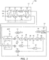
- FIG. 2 is a block diagram schematically illustrating a modification of the system frequency detector according to the first embodiment.
- the rate limiter 46 is provided after the arithmetic unit 45 that multiplies 1/2 ⁇ .
- the rate limiter 46 may directly limit a change of the system frequency f equal to or greater than the prescribed change rate after being converted from the angular frequency ⁇ .
- the rate limiter 46 may be provided before the arithmetic unit 45 or may be provided after the arithmetic unit 45.
- the rate limiter 46 may limit a change of the system frequency f equal to or greater than the prescribed change rate by limiting a change of the angular frequency ⁇ equal to or greater than the prescribed change rate or may directly limit a change of the system frequency f equal to or greater than the prescribed change rate.
- the configuration of the rate limiter 46 may be any configuration in which the rate limiter 46 is provided in series with the arithmetic unit 45 and can limit a change of the system frequency f equal to or greater than the prescribed change rate.
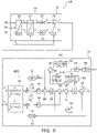
- FIG. 3 is a block diagram schematically illustrating a system frequency detector according to a second embodiment.
- the low-pass filter 44 suppresses the high frequency components of the angular frequency ⁇ .
- the low-pass filter 44 attenuates frequency components of the angular frequency ⁇ that are greater than a prescribed frequency. In other words, the low-pass filter 44 suppresses an abrupt fluctuation of the angular frequency ⁇ .
- the low-pass filter 44 may use a moving average filter.
- the low-pass filter 44 inputs, to the arithmetic unit 45, the angular frequency ⁇ after the high frequency components are suppressed.
- the low-pass filter 44 is provided in series with the arithmetic unit 45.
- the low-pass filter 44 suppresses the high frequency components of the system frequency f by suppressing the high frequency components of the angular frequency ⁇ .
- the low-pass filter 44 suppresses an abrupt fluctuation of the system frequency f.
- the low-pass filter 44 is not limited to being between the arithmetic unit 45 and the rate limiter 46, and may be provided before the rate limiter 46 or may be provided after the arithmetic unit 45.
- the configuration of the low-pass filter 44 may be any configuration in which the low-pass filter 44 is provided in series with the arithmetic unit 45 and can suppress the high frequency components of the system frequency f.
- FIG. 4 is a block diagram schematically illustrating a system frequency detector according to a third embodiment.
- the frequency calculator 14 further includes subtractors 47 and 48.
- the subtractor 47 is connected to the input and output sides of the rate limiter 46.
- the subtractor 47 subtracts the output value of the rate limiter 46 from the input value of the rate limiter 46.
- the subtractor 47 calculates the difference between the input value and the output value of the rate limiter 46.
- the difference between the output value of the rate limiter 46 and the input value of the rate limiter 46 is calculated by the subtractor 47 when the calculated value of the angular frequency ⁇ abruptly increases, the angular frequency ⁇ is limited by the rate limiter 46, and the output value of the rate limiter 46 becomes less than the input value of the rate limiter 46.
- the subtractor 47 inputs the calculation result of the difference to the subtractor 48.
- the subtractor 48 is provided between the arithmetic unit 37 and the integrator 38 of the angular frequency calculator AFP.
- the subtractor 48 subtracts the calculation result of the difference of the subtractor 47 from the multiplication result of the arithmetic unit 37 multiplying the error phase ⁇ by the integral gain K I .
- the subtractor 48 subtracts the amount limited by the rate limiter 46 from the calculation of the integration operation of the proportional-integral control.
- the subtractors 47 and 48 are provided and feed back the output-input difference of the rate limiter 46 to the calculation of the proportional-integral control of the angular frequency calculator AFP.
- an abrupt fluctuation of the system frequency f can be more reliably suppressed, and the error of the calculation of the system frequency f can be reduced further.
- such a control of the feedback may be called Anti reset wind up.
- FIG. 5 is a block diagram schematically illustrating a system frequency detector according to a fourth embodiment.
- the frequency calculator 14 further includes a saturation limiter 50, a switching element 51, and a switching circuit 52.
- the saturation limiter 50 is provided in parallel with the rate limiter 46.
- the rate limiter 46 is provided between the adder 40 and the low-pass filter 44; similarly to the rate limiter 46, the saturation limiter 50 also is provided between the adder 40 and the low-pass filter 44.
- the saturation limiter 50 when the rate limiter 46 is provided between the low-pass filter 44 and the arithmetic unit 45, it is sufficient for the saturation limiter 50 also to be similarly provided between the low-pass filter 44 and the arithmetic unit 45.
- the switching element 51 is provided between the rate limiter 46 and the arithmetic unit 45 (the low-pass filter 44) and between the saturation limiter 50 and the arithmetic unit 45 (the low-pass filter 44).
- the switching element 51 selectively switches between a state in which the rate limiter 46 is connected in series to the arithmetic unit 45 and a state in which the saturation limiter 50 is connected in series to the arithmetic unit 45.
- the subtractor 47 is connected to the input and output sides of the rate limiter 46. Accordingly, in this state, the output-input difference of the rate limiter 46 is fed back to the calculation of the proportional-integral control.
- the subtractor 47 is connected to the input and output sides of the saturation limiter 50. Accordingly, in this state, the output-input difference of the saturation limiter 50 is fed back to the calculation of the proportional-integral control.
- the saturation limiter 50 limits a change of the system frequency f equal to or greater than a prescribed value with respect to the nominal system frequency f n by limiting a change of the angular frequency ⁇ equal to or greater than a prescribed value with respect to the nominal angular frequency ⁇ n .
- the prescribed value (the prescribed absolute value) is, for example, 0.5 Hz.
- the saturation limiter 50 limits the change of the system frequency f to be within the range of 50 Hz ⁇ 0.5 Hz.
- the rate limiter 46 suppresses a change of the system frequency f equal to or greater than 25 Hz/sec.
- the prescribed value (e.g., 0.5 Hz) of the change of the system frequency f limited by the saturation limiter 50 is, for example, less than the frequency (e.g., 25 Hz) of the change rate per unit time (1 second) of the rate limiter 46.
- the switching circuit 52 selectively switches between the first state in which the rate limiter 46 is used and the second state in which the saturation limiter 50 is used. For example, the switching circuit 52 selectively switches between the first state and the second state by controlling the switching of the paths by the switching element 51.
- the switching between the first state and the second state is not limited thereto.
- the first state and the second state may be switched by selectively operating the rate limiter 46 and the saturation limiter 50 by selectively supplying power to the rate limiter 46 and the saturation limiter 50, or the first state and the second state may be switched by selectively operating the rate limiter 46 and the saturation limiter 50 by selectively transmitting control signals to the rate limiter 46 and the saturation limiter 50.
- the switching element 51 is omissible in such cases. It is sufficient for the switching element 51 to be provided as necessary.
- FIG. 6 is a block diagram schematically illustrating the switching circuit.
- the switching circuit 52 includes a differential circuit 53, an absolute value calculation circuit 54, and a determination circuit 55.
- the voltage signal V d that is calculated by the rotating coordinate converter 21 is input to the switching circuit 52.
- the differential circuit 53 calculates a differential of the voltage signal V d . In other words, the differential circuit 53 calculates the slope of the voltage signal V d .
- the absolute value calculation circuit 54 calculates the absolute value of the differential of the voltage signal V d calculated by the differential circuit 53.
- the determination circuit 55 determines whether or not the absolute value of the differential of the voltage signal V d is equal to or greater than a prescribed value.
- the voltage signal V d of the d-axis component of the three-phase alternating current power of the power system abruptly changes (referring to FIG. 7D ). Therefore, when the absolute value of the differential of the voltage signal V d is equal to or greater than the prescribed value, it can be considered that a phase jump has occurred in the power system.
- the determination circuit 55 switches the path of the switching element 51.
- the determination circuit 55 sets the switching element 51 to a state in which the output of the rate limiter 46 is connected to the low-pass filter 44. In other words, the determination circuit 55 selects the first state in which the rate limiter 46 is used when it is determined that a phase jump has not occurred in the power system.
- the determination circuit 55 sets the switching element 51 to a state in which the output of the saturation limiter 50 is connected to the low-pass filter 44. In other words, the determination circuit 55 selects the second state in which the saturation limiter 50 is used when it is determined that a phase jump has occurred in the power system.
- the switching circuit 52 selects the first state when the absolute value of the differential of the voltage signal V d of the active component is less than the prescribed value, and selects the second state when the absolute value of the differential of the voltage signal V d of the active component is equal to or greater than the prescribed value.
- the determination circuit 55 When switching from the first state to the second state, for example, the determination circuit 55 returns the second state to the first state after a prescribed period of time has elapsed from the timing of the switching from the first state to the second state. For example, after switching from the first state to the second state, the determination circuit 55 may return the second state to the first state by responding to the absolute value of the differential of the voltage signal V d returning to be less than the prescribed value.
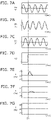
- FIGS. 7A to 7G are graphs schematically illustrating an example of an operation of the system frequency detector.
- FIGS. 7A to 7G the horizontal axis is time.
- the vertical axis of FIG. 7A is an example of the three-phase voltage signal V a .
- the vertical axis of FIG. 7B is an example of the three-phase voltage signal V b .
- the vertical axis of FIG. 7C is an example of the three-phase voltage signal V c .
- the vertical axis of FIG. 7D is an example of the voltage signal V d of the rotating coordinate system.
- the vertical axis of FIG. 7E is an example of a reference system frequency f calculated by the arithmetic unit 45 from the angular frequency ⁇ calculated by the adder 40 as-is without passing through the low-pass filter 44, etc.
- the vertical axis of FIG. 7F is an example of the system frequency f calculated by the configuration of the system frequency detector 10c.
- the vertical axis of FIG. 7G is an example of the system frequency f calculated by the configuration of the system frequency detector 10d.
- FIGS. 7A to 7G illustrate an example when a phase jump of about 30 degrees occurs at a time T1. Also, the actual system frequency of the power system is set to 50 Hz in FIGS. 7A to 7G .
- the mismeasurement can be suppressed to about 1 Hz when the phase jump occurs.
- the mismeasurement when the phase jump occurs can be suppressed further.
- the mismeasurement can be suppressed to about 0.01 Hz.
- the mismeasurement of the system frequency f when the phase jump occurs can be suppressed to the width of the limit of the saturation limiter 50.
- FIG. 8 is a block diagram schematically illustrating a system frequency detector according to a fifth embodiment.
- the saturation limiter 50 of the system frequency detector 10d is replaced with a slow rate limiter 60.
- the slow rate limiter 60 limits the change of the system frequency f at a lower change rate than the change rate of the rate limiter 46.
- the switching circuit 52 selectively switches between the first state in which the rate limiter 46 is used and the second state in which the slow rate limiter 60 is used. Similarly to the embodiments described above, the switching circuit 52 selects the first state when the absolute value of the differential of the voltage signal V d of the active component is less than a prescribed value, and selects the second state when the absolute value of the differential of the voltage signal V d of the active component is equal to or greater than the prescribed value.
- the mismeasurement when the phase jump occurs can be suppressed further compared to the configuration of the system frequency detector 10c that feeds back the output-input difference of the rate limiter 46 to the calculation of the proportional-integral control.
- FIG. 9 is a block diagram schematically illustrating a system frequency detector according to a sixth embodiment.
- the saturation limiter 50 is provided in series with the rate limiter 46. Also, in the system frequency detector 10f, the switching element 51 selectively switches between a state in which only the rate limiter 46 is connected in series to the arithmetic unit 45, and a state in which the rate limiter 46, the saturation limiter 50, and the arithmetic unit 45 are connected in series.
- the subtractor 47 is connected to the input and output sides of the rate limiter 46. Accordingly, in this state, the output-input difference of the rate limiter 46 is fed back to the calculation of the proportional-integral control.
- the subtractor 47 is connected to the input and output sides of a series-connected unit of the rate limiter 46 and the saturation limiter 50.
- the switching circuit 52 selectively switches between the first state in which only the rate limiter 46 is used and the second state in which the series-connected unit of the rate limiter 46 and the saturation limiter 50 is used.
- the switching circuit 52 selectively switches between the first state and the second state by controlling the switching of the paths by the switching element 51.
- the switching between the first state and the second state is not limited thereto.
- the first state may be set by operating only the rate limiter 46
- the second state may be set by operating the rate limiter 46 and the saturation limiter 50.
- the switching element 51 is omissible.
- the switching circuit 52 selects the first state when the absolute value of the differential of the voltage signal V d of the active component is less than a prescribed value, and selects the second state when the absolute value of the differential of the voltage signal V d of the active component is equal to or greater than the prescribed value.
- the frequency that is limited by the saturation limiter 50 is set to be less than the frequency limited by the rate limiter 46. Accordingly, in this state, substantially, the output of the saturation limiter 50 is used in the calculation of the system frequency f, and the output-input difference of the saturation limiter 50 is fed back to the calculation of the proportional-integral control. Therefore, effects similar to those of the system frequency detector 10d in which the saturation limiter 50 is provided in parallel with the rate limiter 46 can be obtained also in the system frequency detector 10f in which the saturation limiter 50 is provided in series with the rate limiter 46.
- the slow rate limiter 60 may be provided in series with the rate limiter 46. In such a case, effects similar to those of the system frequency detector 10e can be obtained.
- FIG. 10 is a block diagram schematically illustrating a system frequency detector according to a seventh embodiment.
- the saturation limiter 50 of the system frequency detector 10d is replaced with a sample-and-hold circuit 62.
- the sample-and-hold circuit 62 includes a sample mode in which the output signal is caused to track the input signal, and a hold mode in which the output signal is held to be substantially constant at a value of a prescribed timing.
- the switching circuit 52 selectively switches between the first state in which the rate limiter 46 is used and the second state in which the sample-and-hold circuit 62 is used.
- the switching circuit 52 selects the first state in which the rate limiter 46 is used and operates the sample-and-hold circuit 62 in the sample mode.
- the switching circuit 52 selects the second state in which the sample-and-hold circuit 62 is used and switches the sample-and-hold circuit 62 from the sample mode to the hold mode. Thereby, the switching circuit 52 causes the sample-and-hold circuit 62 to maintain the signal (the angular frequency ⁇ or the system frequency f) directly before the phase jump occurs in the power system.
- the mismeasurement when the phase jump occurs can be suppressed further compared to the configuration of the system frequency detector 10c in which the output-input difference of the rate limiter 46 is fed back to the calculation of the proportional-integral control.
- the mismeasurement of the system frequency f due to the occurrence of the phase jump can be more reliably suppressed by causing the sample-and-hold circuit 62 to maintain the signal directly before the phase jump occurs in the power system.
- FIG. 11 is a block diagram schematically illustrating a system frequency detector according to an eighth embodiment.
- the angular frequency calculator AFP of a frequency calculator 14a includes a rotating coordinate converter 70, an integrator 71, adders 72 and 73, an arithmetic unit 74, an integrator 75, an arithmetic unit 76, and a subtractor 77.
- the two-phase voltage signals V ⁇ ' and V ⁇ ' are input to the rotating coordinate converter 70, and the synchronous phase ⁇ PLL is input to the rotating coordinate converter 70.
- the rotating coordinate converter 70 uses a so-called dq transformation (a Park transformation) to perform a rotating coordinate transformation of the voltage signals V ⁇ ' and V ⁇ ' of the orthogonal two-axis coordinates into voltage signals V d and v q of a coordinate system (dq coordinates) synchronized with the synchronous phase ⁇ PLL .
- the integrator 71 calculates the command value ⁇ of the angular frequency for setting the voltage signal v q of the q-axis component of the three-phase alternating current power of the power system to zero by multiplying the voltage signal v q by the integral gain K I and by integrating the multiplication result.
- the integrator 71 inputs the calculated command value ⁇ to the adder 72.
- the command value ⁇ of the angular frequency calculated by the integrator 71 is input to the adder 72, and the nominal angular frequency ⁇ n of the power system is input to the adder 72.
- the adder 72 calculates the angular frequency ⁇ of the power system by adding the command value ⁇ of the angular frequency and the nominal angular frequency ⁇ n of the power system.
- the adder 72 inputs the calculated angular frequency ⁇ to the adder 73.
- the arithmetic unit 74 multiplies the voltage signal v q by the proportional gain K P and inputs the multiplication result to the adder 73.
- the adder 73 corrects the angular frequency ⁇ by adding the angular frequency ⁇ calculated by the adder 72 and the multiplication result of the arithmetic unit 74.
- the integrator 75 calculates the synchronous phase ⁇ PLL that is synchronized with the voltage signals V ⁇ ' and V ⁇ ' after the two-phase conversion from the angular frequency ⁇ by integrating the angular frequency ⁇ after being corrected by the adder 73.
- the integrator 75 inputs the calculated synchronous phase ⁇ PLL to the subtractor 77.
- the arithmetic unit 76 calculates the correction value by multiplying the integration result of the integrator 71 by the constant K ⁇ .
- the arithmetic unit 76 inputs the calculated correction value to the subtractor 77.
- the subtractor 77 corrects the synchronous phase ⁇ PLL by subtracting the correction value from the synchronous phase ⁇ PLL .
- the subtractor 77 inputs the synchronous phase ⁇ PLL after the correction to the rotating coordinate converter 70.
- the rotating coordinate converter 70 calculates the voltage signals V d and v q based on the synchronous phase ⁇ PLL after the correction.
- the angular frequency calculator AFP of the frequency calculator 14a synchronizes the synchronous phase ⁇ PLL with the phase ⁇ n of the power system by feeding back the detected synchronous phase ⁇ PLL to the rotating coordinate converter 70 and by detecting the synchronous phase ⁇ PLL to cause the voltage signal v q of the q-axis component of the three-phase alternating current power of the power system to be zero.
- the angular frequency calculator AFP of the frequency calculator 14a Based on the angular frequency ⁇ , the angular frequency calculator AFP of the frequency calculator 14a generates the voltage signal v q of the q-axis component of the three-phase alternating current power of the power system and calculates the angular frequency ⁇ to cause the voltage signal v q of the reactive component to be zero by detecting the synchronous phase ⁇ PLL synchronized with the two-phase voltage signals V ⁇ ' and V ⁇ ' after calculating the moving averages and by performing a rotating coordinate transformation of the two-phase voltage signals V ⁇ ' and V ⁇ ' after calculating the moving averages.
- the configuration of the PLL of the angular frequency calculator AFP (the frequency calculator 14a) of the example may be called an EPMAFPLL (Enhanced Pre-filtering Moving Average Filter PLL).
- the frequency calculator 14a calculates the system frequency f of the power system from the calculated angular frequency ⁇ .
- the frequency calculator 14a further includes a rate limiter 78 and an arithmetic unit 79.
- the adder 73 inputs the calculated angular frequency ⁇ to the integrator 75 and inputs the angular frequency ⁇ to the rate limiter 78.
- the rate limiter 78 limits a change of the angular frequency ⁇ equal to or greater than a prescribed change rate.
- the rate limiter 78 inputs, to the arithmetic unit 79, the angular frequency ⁇ that is less than the prescribed change rate or the angular frequency ⁇ after being limited to the prescribed change rate.
- the arithmetic unit 79 calculates the system frequency f from the angular frequency ⁇ by multiplying the angular frequency ⁇ by 1/2 ⁇ .
- the rate limiter 78 may be provided after the arithmetic unit 79.
- the configuration of the frequency calculator may be an EPMAFPLL configuration or may be an ⁇ EPMAFPLL configuration.
- the configuration of the frequency calculator is not limited to these configurations.
- the configuration of the frequency calculator may be, for example, a PMAFPLL (Pre-filtering Moving Average Filter PLL) configuration in which the arithmetic unit 76 and the subtractor 77 are omitted from an EPMAFPLL configuration and the synchronous phase ⁇ PLL calculated by the integrator 75 is fed back to the rotating coordinate converter 70 as-is.
- PMAFPLL Pre-filtering Moving Average Filter PLL
- the configuration of the frequency calculator may be an EPMAFPLL Type-2 configuration, etc., in which the integration result of the integrator 71 is multiplied by the constant K ⁇ , and the calculated correction value is fed back to the inverse converter 24 and the rotating coordinate converter 21 of the orthogonal coordinate signal generator 12.
- an Anti reset wind up feedback control may be added to the EPMAFPLL configuration illustrated in FIG. 11 .
- the integrator 71 it is sufficient for the integrator 71 to be divided into an arithmetic unit multiplying the integral gain K I by the voltage signal v q and an integrator integrating the multiplication result similarly to the example illustrated in FIG. 4 , etc., and for the output-input difference of the rate limiter 78 to be fed back to the calculation of the proportional-integral control by providing a subtractor between the arithmetic unit and the integrator.
- system frequency detectors practicable by an appropriate design modification by one skilled in the art based on the system frequency detectors 10 and 10a to 10h described above as embodiments of the invention also are within the scope of the invention to the extent that the spirit of the invention is included.
Landscapes
- Physics & Mathematics (AREA)
- General Physics & Mathematics (AREA)
- Nonlinear Science (AREA)
- Inverter Devices (AREA)
- Control Of Eletrric Generators (AREA)
Abstract
Description
- Embodiments of the invention relate to a system frequency detector.
- A zero crossing point detection-type frequency calculation is known as a technique of detecting a system frequency of a power system. The zero crossing point detection-type frequency calculation can take measurement data only in intervals synchronized with the system frequency; ordinarily, a filter of a relatively long time constant of 200 msec or more has been provided to acquire resistance to system disturbances. Therefore, for example, rapid output tracking for a change of the system frequency such as tracking with a delay of 40 msec or less, etc., is difficult.
- Also, a frequency calculation using PLL (Phase Locked Loop) using a DQ transformation also is known. Such a frequency calculation using PLL can be used as a good frequency detector if there is no trouble at the power system side, and the system frequency can be tracked more quickly than the zero crossing point detection-type frequency calculation. However, there are cases where the calculated frequency temporarily oscillates greatly when a phase jump occurs in the system voltage.
- Therefore, in a system frequency detector, it is desirable to be able to quickly track the change of the system frequency and to be able to suppress an erroneous detection of the system frequency even when a system disturbance occurs.
- [PTL 1]
U.S. Patent No. 8704571 - Embodiments of the invention provide a system frequency detector in which the change of the system frequency can be quickly tracked and an erroneous detection of the system frequency can be suppressed even when a system disturbance occurs.
- According to an embodiment of the invention, a system frequency detector is provided and includes: an orthogonal coordinate signal generator generating an orthogonal two-phase voltage signal from a three-phase voltage signal of three-phase alternating current power of a power system by converting the three-phase voltage signal into a two-phase voltage signal orthogonal to the three-phase voltage signal, converting the two-phase voltage signal into a voltage signal of a rotating coordinate system, calculating a moving average of the voltage signal of the rotating coordinate system, and performing an inverse transformation of the voltage signal of the rotating coordinate system after calculating the moving average; and a frequency calculator including an angular frequency calculator calculating an angular frequency of the power system based on the two-phase voltage signal after calculating the moving average generated by the orthogonal coordinate signal generator, and an arithmetic unit calculating a system frequency of the power system from the angular frequency by multiplying the angular frequency by 1/2π, wherein the frequency calculator further includes a rate limiter that is provided in series with the arithmetic unit and limits a change of the system frequency equal to or greater than a prescribed change rate.
- According to embodiments of the invention, a system frequency detector is provided in which the change of the system frequency can be quickly tracked and an erroneous detection of the system frequency can be suppressed even when a system disturbance occurs.
-
- [
FIG. 1] FIG. 1 is a block diagram schematically illustrating a system frequency detector according to a first embodiment. - [
FIG. 2] FIG. 2 is a block diagram schematically illustrating a modification of the system frequency detector according to the first embodiment. - [
FIG. 3] FIG. 3 is a block diagram schematically illustrating a system frequency detector according to a second embodiment. - [
FIG. 4] FIG. 4 is a block diagram schematically illustrating a system frequency detector according to a third embodiment. - [
FIG. 5] FIG. 5 is a block diagram schematically illustrating a system frequency detector according to a fourth embodiment. - [
FIG. 6] FIG. 6 is a block diagram schematically illustrating the switching circuit. - [
FIG. 7] FIGS. 7A to 7G are graphs schematically illustrating an example of an operation of the system frequency detector. - [
FIG. 8] FIG. 8 is a block diagram schematically illustrating a system frequency detector according to a fifth embodiment. - [
FIG. 9] FIG. 9 is a block diagram schematically illustrating a system frequency detector according to a sixth embodiment. - [
FIG. 10] FIG. 10 is a block diagram schematically illustrating a system frequency detector according to a seventh embodiment. - [
FIG. 11] FIG. 11 is a block diagram schematically illustrating a system frequency detector according to an eighth embodiment. - Embodiments will now be described with reference to the drawings.
- The drawings are schematic and conceptual; and the relationships between the thicknesses and widths of portions, the proportions of sizes among portions, etc., are not necessarily the same as the actual values. The dimensions and/or the proportions may be illustrated differently among drawings even in the case where the same portion is illustrated.
- In the specification and drawings, components similar to those described previously or illustrated in an antecedent drawing are marked with the same reference numerals; and a detailed description is omitted as appropriate.
-
FIG. 1 is a block diagram schematically illustrating a system frequency detector according to a first embodiment. - As illustrated in
FIG. 1 , thesystem frequency detector 10 includes an orthogonalcoordinate signal generator 12 and afrequency calculator 14. Thesystem frequency detector 10 detects the system frequency of a power system of three-phase alternating current power. - For example, the
system frequency detector 10 is used in a power conversion device in which a distributed power source such as solar power generation, wind power generation, or the like is connected to a power system, etc. However, applications of thesystem frequency detector 10 are not limited thereto. Thesystem frequency detector 10 can be used in any device in which it is necessary to detect the system frequency of a power system of three-phase alternating current power. - The orthogonal
coordinate signal generator 12 generates orthogonal two-phase voltage signals Vα' and Vβ' from three-phase voltage signals Va, Vb, and Vc of the three-phase alternating current power of the power system. For example, the three-phase voltage signals Va, Vb, and Vc are detected by a voltage detector or the like and are input to the orthogonalcoordinate signal generator 12. For example, the three-phase voltage signals Va, Vb, and Vc are instantaneous values of a three-phase alternating current voltage input at a prescribed sampling interval. - The orthogonal
coordinate signal generator 12 includes a three-phase to two-phase converter 20, arotating coordinate converter 21, movingaverage filters inverse converter 24. - The three-phase to two-
phase converter 20 converts the three-phase voltage signals Va, Vb, and Vc into two-phase voltage signals Vα and Vβ of an α-phase and a β-phase by performing an α-β transform (a Clarke transformation). - The two-phase voltage signals Vα and Vβ are input to the rotating
coordinate converter 21, and a nominal phase θn obtained by integrating a nominal angular frequency ωn of the power system is input to the rotatingcoordinate converter 21. The rotatingcoordinate converter 21 performs a rotating coordinate transformation of the voltage signals Vα and Vβ of the orthogonal two-axis coordinates into voltage signals Vd and Vq of a coordinate system (dq coordinates) synchronized with the phase θn by a so-called dq transformation (a Park transformation). The voltage signal Vd is a voltage signal of the d-axis component of the three-phase alternating current power (the voltage signals Va, Vb, and Vc) of the power system, and the voltage signal Vq is a voltage signal of the q-axis component of the three-phase alternating current power (the voltage signals Va, Vb, and Vc) of the power system. - The moving
average filter 22 outputs a voltage signal Vd' after the moving average calculation by calculating the moving average of the voltage signal Vd. Similarly, the movingaverage filter 23 outputs a voltage signal Vq' after the moving average calculation by calculating the moving average of the voltage signal Vq. Thus, the movingaverage filters average filters - By performing an inverse transformation of the voltage signal Vd' and Vq' of the rotating coordinate system into an orthogonal two-axis coordinate system, the
inverse converter 24 converts the voltage signal Vd' and Vq' into the voltage signals Vα' and Vβ' of the orthogonal two-axis coordinates after the moving average calculation. Thereby, the orthogonalcoordinate signal generator 12 generates the orthogonal two-phase voltage signals Vα' and Vβ' from the three-phase voltage signals Va, Vb, and Vc. - The
frequency calculator 14 calculates a system frequency f of the power system based on the two-phase voltage signals Vα' and Vβ' generated by the orthogonalcoordinate signal generator 12. By using a PLL (Phase-Locked-Loop) calculation, thefrequency calculator 14 detects a synchronous phase θαβPLL synchronized with the voltage signals Vα' and Vβ' after the two-phase conversion and calculates the system frequency f of the power system from an angular frequency ω obtained in the detection process of the synchronous phase θαβPLL. - The
frequency calculator 14 includes an angular frequency calculator AFP. The angular frequency calculator AFP includes, for example,arithmetic units multipliers subtractor 35,arithmetic units integrator 38,adders integrator 41, anarithmetic unit 42, and asubtractor 43. - The
arithmetic unit 30 calculates cosθn and sinθn from the two-phase voltage signals Vα' and Vβ'. Thearithmetic unit 30 calculates cosθn by using the formula Vα'/√(Vα '2 + Vβ' 2), and calculates sinθn by using the formula Vβ'/√(Vα' 2 + Vβ' 2). Thearithmetic unit 30 inputs the calculated cosθn to themultiplier 33, and inputs the calculated sinθn to themultiplier 34. - The
arithmetic unit 31 calculates sinθαβPLL based on the detected synchronous phase θαβPLL and inputs sinθαβPLL to themultiplier 33. - The
arithmetic unit 32 calculates cosθαβPLL based on the detected synchronous phase θαβPLL and inputs cosθαβPLL to themultiplier 34. - The
multiplier 33 multiplies the input cosθn and sinθαβPLL and inputs the multiplication result to thesubtractor 35. - The
multiplier 34 multiplies the input sinθn and cosθαβPLL and inputs the multiplication result to thesubtractor 35. - The
subtractor 35 calculates an error phase Δθ between the phase θn of the power system and the synchronous phase θαβPLL by calculating sinθn and cosθαβPLL - cosθn and sinθαβPLL. Thefrequency calculator 14 calculates the error phase Δθ as
- The
arithmetic unit 36 multiplies the error phase Δθ by a proportional gain Kp and inputs the multiplication result to theadder 39. - The
arithmetic unit 37 multiplies the error phase Δθ by an integral gain KI and inputs the multiplication result to theintegrator 38. - The
integrator 38 integrates the multiplication result of the error phase Δθ and the integral gain KI and inputs the integral to theadder 39. - The
adder 39 adds the multiplication result of thearithmetic unit 36 and the integral of theintegrator 38. Thearithmetic units integrator 38, and theadder 39 calculate a command value Δω of the angular frequency for setting the error phase Δθ to zero by so-called proportional-integral control. - The command value Δω of the angular frequency calculated by the
adder 39 is input to theadder 40, and the nominal angular frequency ωn of the power system is input to theadder 40. Theadder 40 calculates the angular frequency ω of the power system by adding the command value Δω of the angular frequency and the nominal angular frequency ωn of the power system. Thus, the angular frequency calculator AFP calculates the angular frequency ω by performing the proportional-integral control based on the two-phase voltage signals Vα' and Vβ'. - The
integrator 41 calculates a synchronous phase θ from the angular frequency ω by integrating the angular frequency ω calculated by theadder 40. Theintegrator 41 inputs the calculated synchronous phase θ to thesubtractor 43. - The
arithmetic unit 42 calculates a correction value by multiplying the integration result of theintegrator 38 by a constant Kφ. The constant Kφ is determined by Kφ = (Tω - TSP )/2. TSP is the sampling interval of the voltage signals Va, Vb, and Vc. Tω , is the window length of the movingaverage filters average filters arithmetic unit 42 inputs the calculated correction value to thesubtractor 43. - The
subtractor 43 corrects the synchronous phase θ by subtracting the correction value from the synchronous phase θ. Thesubtractor 43 calculates the synchronous phase θαβPLL by the correction. - The angular frequency calculator AFP synchronizes the synchronous phase θαβPLL with the phase θn of the power system by feeding back the detected synchronous phase θαβPLL. to the
arithmetic units - The
frequency calculator 14 further includes anarithmetic unit 45 and arate limiter 46. Thefrequency calculator 14 calculates the system frequency f of the power system from the calculated angular frequency ω. Theadder 40 inputs the calculated angular frequency ω to theintegrator 41 and inputs the angular frequency ω to therate limiter 46. - The
rate limiter 46 limits a change of the angular frequency ω equal to or greater than a prescribed change rate. Therate limiter 46 inputs, to thearithmetic unit 45, the angular frequency ω that is less than the prescribed change rate or the angular frequency ω after being limited to the prescribed change rate. - The
arithmetic unit 45 calculates the system frequency f from the angular frequency ω by multiplying the angular frequency ω by 1/2π. Therate limiter 46 is provided in series with thearithmetic unit 45. By limiting a change of the angular frequency ω equal to or greater than the prescribed change rate, therate limiter 46 limits a change of the system frequency f equal to or greater than a prescribed change rate. For example, therate limiter 46 suppresses a change of the system frequency f equal to or greater than 25 Hz/sec. Therate limiter 46 suppresses an abrupt fluctuation of the system frequency f. - Thus, the
frequency calculator 14 calculates the system frequency f of the power system from the two-phase voltage signals Vα' and Vβ'. Thesystem frequency detector 10 detects the system frequency f of the power system from the three-phase voltage signals Va, Vb, and Vc. - As described above, the
system frequency detector 10 according to the embodiment includes therate limiter 46 that limits a change of the system frequency f equal to or greater than the prescribed change rate. Thereby, even when a phase jump or the like occurs in the power system, an abrupt fluctuation of the system frequency f can be suppressed, and the error of the calculation of the system frequency f can be reduced. Also, the calculation of the system frequency f is an open loop; therefore, effects on the speed of the system voltage phase tracking by PLL can be suppressed even when therate limiter 46 is provided in the part calculating the system frequency f. Accordingly, thesystem frequency detector 10 can be provided in which the change of the system frequency f can be quickly tracked, and an erroneous detection of the system frequency f can be suppressed even when a system disturbance occurs. -
FIG. 2 is a block diagram schematically illustrating a modification of the system frequency detector according to the first embodiment. - Components that are substantially the same functionally and configurationally as those of the embodiments described above are marked with the same reference numerals, and a detailed description is omitted.
- In the
system frequency detector 10a as illustrated inFIG. 2 , therate limiter 46 is provided after thearithmetic unit 45 that multiplies 1/2π. Thus, therate limiter 46 may directly limit a change of the system frequency f equal to or greater than the prescribed change rate after being converted from the angular frequency ω. - Thus, the
rate limiter 46 may be provided before thearithmetic unit 45 or may be provided after thearithmetic unit 45. Therate limiter 46 may limit a change of the system frequency f equal to or greater than the prescribed change rate by limiting a change of the angular frequency ω equal to or greater than the prescribed change rate or may directly limit a change of the system frequency f equal to or greater than the prescribed change rate. The configuration of therate limiter 46 may be any configuration in which therate limiter 46 is provided in series with thearithmetic unit 45 and can limit a change of the system frequency f equal to or greater than the prescribed change rate. -
FIG. 3 is a block diagram schematically illustrating a system frequency detector according to a second embodiment. - In the
system frequency detector 10b as illustrated inFIG. 3 , thefrequency calculator 14 further includes a low-pass filter 44. The low-pass filter 44 is provided in series with thearithmetic unit 45. For example, the low-pass filter 44 is provided between thearithmetic unit 45 and therate limiter 46. - The low-
pass filter 44 suppresses the high frequency components of the angular frequency ω. The low-pass filter 44 attenuates frequency components of the angular frequency ω that are greater than a prescribed frequency. In other words, the low-pass filter 44 suppresses an abrupt fluctuation of the angular frequency ω. For example, the low-pass filter 44 may use a moving average filter. The low-pass filter 44 inputs, to thearithmetic unit 45, the angular frequency ω after the high frequency components are suppressed. - The low-
pass filter 44 is provided in series with thearithmetic unit 45. The low-pass filter 44 suppresses the high frequency components of the system frequency f by suppressing the high frequency components of the angular frequency ω. The low-pass filter 44 suppresses an abrupt fluctuation of the system frequency f. - Thus, by providing the low-
pass filter 44, even when a phase jump or the like occurs in the power system, an abrupt fluctuation of the system frequency f can be suppressed, and the error of the calculation of the system frequency f can be reduced further. - The low-
pass filter 44 is not limited to being between thearithmetic unit 45 and therate limiter 46, and may be provided before therate limiter 46 or may be provided after thearithmetic unit 45. The configuration of the low-pass filter 44 may be any configuration in which the low-pass filter 44 is provided in series with thearithmetic unit 45 and can suppress the high frequency components of the system frequency f. -
FIG. 4 is a block diagram schematically illustrating a system frequency detector according to a third embodiment. - In the
system frequency detector 10c as illustrated inFIG. 4 , thefrequency calculator 14 further includessubtractors subtractor 47 is connected to the input and output sides of therate limiter 46. Thesubtractor 47 subtracts the output value of therate limiter 46 from the input value of therate limiter 46. In other words, thesubtractor 47 calculates the difference between the input value and the output value of therate limiter 46. The difference between the output value of therate limiter 46 and the input value of therate limiter 46 is calculated by thesubtractor 47 when the calculated value of the angular frequency ω abruptly increases, the angular frequency ω is limited by therate limiter 46, and the output value of therate limiter 46 becomes less than the input value of therate limiter 46. Thesubtractor 47 inputs the calculation result of the difference to thesubtractor 48. - The
subtractor 48 is provided between thearithmetic unit 37 and theintegrator 38 of the angular frequency calculator AFP. Thesubtractor 48 subtracts the calculation result of the difference of the subtractor 47 from the multiplication result of thearithmetic unit 37 multiplying the error phase Δθ by the integral gain KI. In other words, when therate limiter 46 limits the angular frequency ω, thesubtractor 48 subtracts the amount limited by therate limiter 46 from the calculation of the integration operation of the proportional-integral control. - Thus, in the
frequency calculator 14 of thesystem frequency detector 10c, thesubtractors rate limiter 46 to the calculation of the proportional-integral control of the angular frequency calculator AFP. Thereby, even when a phase jump or the like occurs in the power system, an abrupt fluctuation of the system frequency f can be more reliably suppressed, and the error of the calculation of the system frequency f can be reduced further. For example, such a control of the feedback may be called Anti reset wind up. -
FIG. 5 is a block diagram schematically illustrating a system frequency detector according to a fourth embodiment. - In the
system frequency detector 10d as illustrated inFIG. 5 , thefrequency calculator 14 further includes asaturation limiter 50, a switchingelement 51, and aswitching circuit 52. - The
saturation limiter 50 is provided in parallel with therate limiter 46. In the example, therate limiter 46 is provided between theadder 40 and the low-pass filter 44; similarly to therate limiter 46, thesaturation limiter 50 also is provided between theadder 40 and the low-pass filter 44. For example, when therate limiter 46 is provided between the low-pass filter 44 and thearithmetic unit 45, it is sufficient for thesaturation limiter 50 also to be similarly provided between the low-pass filter 44 and thearithmetic unit 45. - The switching
element 51 is provided between therate limiter 46 and the arithmetic unit 45 (the low-pass filter 44) and between thesaturation limiter 50 and the arithmetic unit 45 (the low-pass filter 44). The switchingelement 51 selectively switches between a state in which therate limiter 46 is connected in series to thearithmetic unit 45 and a state in which thesaturation limiter 50 is connected in series to thearithmetic unit 45. - In the state in which the
switching element 51 connects therate limiter 46 to thearithmetic unit 45 in series, thesubtractor 47 is connected to the input and output sides of therate limiter 46. Accordingly, in this state, the output-input difference of therate limiter 46 is fed back to the calculation of the proportional-integral control. - On the other hand, in the state in which the
switching element 51 connects thesaturation limiter 50 to thearithmetic unit 45 in series, thesubtractor 47 is connected to the input and output sides of thesaturation limiter 50. Accordingly, in this state, the output-input difference of thesaturation limiter 50 is fed back to the calculation of the proportional-integral control. - The
saturation limiter 50 limits a change of the system frequency f equal to or greater than a prescribed value with respect to the nominal system frequency fn by limiting a change of the angular frequency ω equal to or greater than a prescribed value with respect to the nominal angular frequency ωn. The prescribed value (the prescribed absolute value) is, for example, 0.5 Hz. For example, when the nominal system frequency fn is 50 Hz, thesaturation limiter 50 limits the change of the system frequency f to be within the range of 50 Hz±0.5 Hz. - As described above, for example, the
rate limiter 46 suppresses a change of the system frequency f equal to or greater than 25 Hz/sec. Thus, the prescribed value (e.g., 0.5 Hz) of the change of the system frequency f limited by thesaturation limiter 50 is, for example, less than the frequency (e.g., 25 Hz) of the change rate per unit time (1 second) of therate limiter 46. - The switching
circuit 52 selectively switches between the first state in which therate limiter 46 is used and the second state in which thesaturation limiter 50 is used. For example, the switchingcircuit 52 selectively switches between the first state and the second state by controlling the switching of the paths by the switchingelement 51. - However, the switching between the first state and the second state is not limited thereto. For example, the first state and the second state may be switched by selectively operating the
rate limiter 46 and thesaturation limiter 50 by selectively supplying power to therate limiter 46 and thesaturation limiter 50, or the first state and the second state may be switched by selectively operating therate limiter 46 and thesaturation limiter 50 by selectively transmitting control signals to therate limiter 46 and thesaturation limiter 50. The switchingelement 51 is omissible in such cases. It is sufficient for the switchingelement 51 to be provided as necessary. -
FIG. 6 is a block diagram schematically illustrating the switching circuit. - As illustrated in
FIG. 6 , the switchingcircuit 52 includes adifferential circuit 53, an absolutevalue calculation circuit 54, and adetermination circuit 55. The voltage signal Vd that is calculated by the rotating coordinateconverter 21 is input to the switchingcircuit 52. - The
differential circuit 53 calculates a differential of the voltage signal Vd. In other words, thedifferential circuit 53 calculates the slope of the voltage signal Vd. The absolutevalue calculation circuit 54 calculates the absolute value of the differential of the voltage signal Vd calculated by thedifferential circuit 53. - The
determination circuit 55 determines whether or not the absolute value of the differential of the voltage signal Vd is equal to or greater than a prescribed value. When a phase jump occurs in the power system, the voltage signal Vd of the d-axis component of the three-phase alternating current power of the power system abruptly changes (referring toFIG. 7D ). Therefore, when the absolute value of the differential of the voltage signal Vd is equal to or greater than the prescribed value, it can be considered that a phase jump has occurred in the power system. - The
determination circuit 55 switches the path of the switchingelement 51. When the absolute value of the differential of the voltage signal Vd is less than the prescribed value, thedetermination circuit 55 sets the switchingelement 51 to a state in which the output of therate limiter 46 is connected to the low-pass filter 44. In other words, thedetermination circuit 55 selects the first state in which therate limiter 46 is used when it is determined that a phase jump has not occurred in the power system. - On the other hand, when the absolute value of the differential of the voltage signal Vd is equal to or greater than the prescribed value, the
determination circuit 55 sets the switchingelement 51 to a state in which the output of thesaturation limiter 50 is connected to the low-pass filter 44. In other words, thedetermination circuit 55 selects the second state in which thesaturation limiter 50 is used when it is determined that a phase jump has occurred in the power system. - Thus, the switching
circuit 52 selects the first state when the absolute value of the differential of the voltage signal Vd of the active component is less than the prescribed value, and selects the second state when the absolute value of the differential of the voltage signal Vd of the active component is equal to or greater than the prescribed value. - When switching from the first state to the second state, for example, the
determination circuit 55 returns the second state to the first state after a prescribed period of time has elapsed from the timing of the switching from the first state to the second state. For example, after switching from the first state to the second state, thedetermination circuit 55 may return the second state to the first state by responding to the absolute value of the differential of the voltage signal Vd returning to be less than the prescribed value. -
FIGS. 7A to 7G are graphs schematically illustrating an example of an operation of the system frequency detector. - In
FIGS. 7A to 7G , the horizontal axis is time. - The vertical axis of
FIG. 7A is an example of the three-phase voltage signal Va. - The vertical axis of
FIG. 7B is an example of the three-phase voltage signal Vb. - The vertical axis of
FIG. 7C is an example of the three-phase voltage signal Vc. - The vertical axis of
FIG. 7D is an example of the voltage signal Vd of the rotating coordinate system. - The vertical axis of
FIG. 7E is an example of a reference system frequency f calculated by thearithmetic unit 45 from the angular frequency ω calculated by theadder 40 as-is without passing through the low-pass filter 44, etc. - The vertical axis of
FIG. 7F is an example of the system frequency f calculated by the configuration of thesystem frequency detector 10c. - The vertical axis of
FIG. 7G is an example of the system frequency f calculated by the configuration of thesystem frequency detector 10d. -
FIGS. 7A to 7G illustrate an example when a phase jump of about 30 degrees occurs at a time T1. Also, the actual system frequency of the power system is set to 50 Hz inFIGS. 7A to 7G . - When a phase jump occurs as illustrated in
FIG. 7D , the voltage signal Vd of the d-axis component of the three-phase alternating current power of the power system abruptly changes. - As illustrated in
FIG. 7E , when the system frequency f is calculated without using the low-pass filter 44, etc., a mismeasurement of about 5 Hz occurs when the phase jump occurs. - Conversely, as illustrated in
FIG. 7F , in thesystem frequency detector 10c in which the output-input difference of therate limiter 46 is fed back to the calculation of the proportional-integral control, the mismeasurement can be suppressed to about 1 Hz when the phase jump occurs. - Also, in the
system frequency detector 10d that switches from therate limiter 46 to thesaturation limiter 50 when the occurrence of a phase jump is detected, the mismeasurement when the phase jump occurs can be suppressed further. In thesystem frequency detector 10d, the mismeasurement can be suppressed to about 0.01 Hz. In other words, in thesystem frequency detector 10d, the mismeasurement of the system frequency f when the phase jump occurs can be suppressed to the width of the limit of thesaturation limiter 50. - Thereby, in the
system frequency detector 10d, even when a phase jump or the like occurs in the power system, an abrupt fluctuation of the system frequency f can be more reliably suppressed, and the error of the calculation of the system frequency f can be reduced further. -
FIG. 8 is a block diagram schematically illustrating a system frequency detector according to a fifth embodiment. - In the
system frequency detector 10e as illustrated inFIG. 8 , thesaturation limiter 50 of thesystem frequency detector 10d is replaced with aslow rate limiter 60. Theslow rate limiter 60 limits the change of the system frequency f at a lower change rate than the change rate of therate limiter 46. - In the example, the switching
circuit 52 selectively switches between the first state in which therate limiter 46 is used and the second state in which theslow rate limiter 60 is used. Similarly to the embodiments described above, the switchingcircuit 52 selects the first state when the absolute value of the differential of the voltage signal Vd of the active component is less than a prescribed value, and selects the second state when the absolute value of the differential of the voltage signal Vd of the active component is equal to or greater than the prescribed value. - Thus, even when switching from the
rate limiter 46 to theslow rate limiter 60 when the occurrence of a phase jump is detected, similarly to when thesaturation limiter 50 is provided, the mismeasurement when the phase jump occurs can be suppressed further compared to the configuration of thesystem frequency detector 10c that feeds back the output-input difference of therate limiter 46 to the calculation of the proportional-integral control. -
FIG. 9 is a block diagram schematically illustrating a system frequency detector according to a sixth embodiment. - In the
system frequency detector 10f as illustrated inFIG. 9 , thesaturation limiter 50 is provided in series with therate limiter 46. Also, in thesystem frequency detector 10f, the switchingelement 51 selectively switches between a state in which only therate limiter 46 is connected in series to thearithmetic unit 45, and a state in which therate limiter 46, thesaturation limiter 50, and thearithmetic unit 45 are connected in series. - In the state in which the
switching element 51 connects only therate limiter 46 to thearithmetic unit 45 in series, thesubtractor 47 is connected to the input and output sides of therate limiter 46. Accordingly, in this state, the output-input difference of therate limiter 46 is fed back to the calculation of the proportional-integral control. - On the other hand, in the state in which the
switching element 51 connects therate limiter 46, thesaturation limiter 50, and thearithmetic unit 45 in series, thesubtractor 47 is connected to the input and output sides of a series-connected unit of therate limiter 46 and thesaturation limiter 50. - The switching
circuit 52 selectively switches between the first state in which only therate limiter 46 is used and the second state in which the series-connected unit of therate limiter 46 and thesaturation limiter 50 is used. For example, the switchingcircuit 52 selectively switches between the first state and the second state by controlling the switching of the paths by the switchingelement 51. - However, the switching between the first state and the second state is not limited thereto. For example, the first state may be set by operating only the
rate limiter 46, and the second state may be set by operating therate limiter 46 and thesaturation limiter 50. In such a case, the switchingelement 51 is omissible. - Similarly to the embodiments described above, the switching
circuit 52 selects the first state when the absolute value of the differential of the voltage signal Vd of the active component is less than a prescribed value, and selects the second state when the absolute value of the differential of the voltage signal Vd of the active component is equal to or greater than the prescribed value. - The frequency that is limited by the
saturation limiter 50 is set to be less than the frequency limited by therate limiter 46. Accordingly, in this state, substantially, the output of thesaturation limiter 50 is used in the calculation of the system frequency f, and the output-input difference of thesaturation limiter 50 is fed back to the calculation of the proportional-integral control. Therefore, effects similar to those of thesystem frequency detector 10d in which thesaturation limiter 50 is provided in parallel with therate limiter 46 can be obtained also in thesystem frequency detector 10f in which thesaturation limiter 50 is provided in series with therate limiter 46. - Instead of the
saturation limiter 50, theslow rate limiter 60 may be provided in series with therate limiter 46. In such a case, effects similar to those of thesystem frequency detector 10e can be obtained. -
FIG. 10 is a block diagram schematically illustrating a system frequency detector according to a seventh embodiment. In thesystem frequency detector 10g as illustrated inFIG. 10 , thesaturation limiter 50 of thesystem frequency detector 10d is replaced with a sample-and-hold circuit 62. - The sample-and-
hold circuit 62 includes a sample mode in which the output signal is caused to track the input signal, and a hold mode in which the output signal is held to be substantially constant at a value of a prescribed timing. - The switching
circuit 52 selectively switches between the first state in which therate limiter 46 is used and the second state in which the sample-and-hold circuit 62 is used. - When the absolute value of the differential of the voltage signal Vd is less than a prescribed value and it is determined that a phase jump has not occurred in the power system, the switching circuit 52 (the determination circuit 55) selects the first state in which the
rate limiter 46 is used and operates the sample-and-hold circuit 62 in the sample mode. - When the absolute value of the differential of the voltage signal Vd is equal to or greater than the prescribed value and it is determined that a phase jump has occurred in the power system, the switching circuit 52 (the determination circuit 55) selects the second state in which the sample-and-
hold circuit 62 is used and switches the sample-and-hold circuit 62 from the sample mode to the hold mode. Thereby, the switchingcircuit 52 causes the sample-and-hold circuit 62 to maintain the signal (the angular frequency ω or the system frequency f) directly before the phase jump occurs in the power system. - Thus, even when switching from the
rate limiter 46 to the sample-and-hold circuit 62 when the occurrence of a phase jump is detected, similarly to when thesaturation limiter 50 is provided, the mismeasurement when the phase jump occurs can be suppressed further compared to the configuration of thesystem frequency detector 10c in which the output-input difference of therate limiter 46 is fed back to the calculation of the proportional-integral control. - As described above, the mismeasurement of the system frequency f due to the occurrence of the phase jump can be more reliably suppressed by causing the sample-and-
hold circuit 62 to maintain the signal directly before the phase jump occurs in the power system. -
FIG. 11 is a block diagram schematically illustrating a system frequency detector according to an eighth embodiment. In thesystem frequency detector 10h as illustrated inFIG. 11 , the angular frequency calculator AFP of afrequency calculator 14a includes a rotating coordinateconverter 70, anintegrator 71,adders arithmetic unit 74, anintegrator 75, anarithmetic unit 76, and asubtractor 77. - The two-phase voltage signals Vα' and Vβ' are input to the rotating coordinate
converter 70, and the synchronous phase θPLL is input to the rotating coordinateconverter 70. The rotating coordinateconverter 70 uses a so-called dq transformation (a Park transformation) to perform a rotating coordinate transformation of the voltage signals Vα' and Vβ' of the orthogonal two-axis coordinates into voltage signals Vd and vq of a coordinate system (dq coordinates) synchronized with the synchronous phase θPLL. - The
integrator 71 calculates the command value Δω of the angular frequency for setting the voltage signal vq of the q-axis component of the three-phase alternating current power of the power system to zero by multiplying the voltage signal vq by the integral gain KI and by integrating the multiplication result. Theintegrator 71 inputs the calculated command value Δω to theadder 72. - The command value Δω of the angular frequency calculated by the
integrator 71 is input to theadder 72, and the nominal angular frequency ωn of the power system is input to theadder 72. Theadder 72 calculates the angular frequency ω of the power system by adding the command value Δω of the angular frequency and the nominal angular frequency ωn of the power system. Theadder 72 inputs the calculated angular frequency ω to theadder 73. - The
arithmetic unit 74 multiplies the voltage signal vq by the proportional gain KP and inputs the multiplication result to theadder 73. - The
adder 73 corrects the angular frequency ω by adding the angular frequency ω calculated by theadder 72 and the multiplication result of thearithmetic unit 74. - The
integrator 75 calculates the synchronous phase θPLL that is synchronized with the voltage signals Vα' and Vβ' after the two-phase conversion from the angular frequency ω by integrating the angular frequency ω after being corrected by theadder 73. Theintegrator 75 inputs the calculated synchronous phase θPLL to thesubtractor 77. - The
arithmetic unit 76 calculates the correction value by multiplying the integration result of theintegrator 71 by the constant Kφ. Thearithmetic unit 76 inputs the calculated correction value to thesubtractor 77. - The
subtractor 77 corrects the synchronous phase θPLL by subtracting the correction value from the synchronous phase θPLL. Thesubtractor 77 inputs the synchronous phase θPLL after the correction to the rotating coordinateconverter 70. As described above, the rotating coordinateconverter 70 calculates the voltage signals Vd and vq based on the synchronous phase θPLL after the correction. - Thus, the angular frequency calculator AFP of the
frequency calculator 14a synchronizes the synchronous phase θPLL with the phase θn of the power system by feeding back the detected synchronous phase θPLL to the rotating coordinateconverter 70 and by detecting the synchronous phase θPLL to cause the voltage signal vq of the q-axis component of the three-phase alternating current power of the power system to be zero. Based on the angular frequency ω, the angular frequency calculator AFP of thefrequency calculator 14a generates the voltage signal vq of the q-axis component of the three-phase alternating current power of the power system and calculates the angular frequency ω to cause the voltage signal vq of the reactive component to be zero by detecting the synchronous phase θPLL synchronized with the two-phase voltage signals Vα' and Vβ' after calculating the moving averages and by performing a rotating coordinate transformation of the two-phase voltage signals Vα' and Vβ' after calculating the moving averages. For example, the configuration of the PLL of the angular frequency calculator AFP (thefrequency calculator 14a) of the example may be called an EPMAFPLL (Enhanced Pre-filtering Moving Average Filter PLL). - Also, the
frequency calculator 14a calculates the system frequency f of the power system from the calculated angular frequency ω. Thefrequency calculator 14a further includes arate limiter 78 and anarithmetic unit 79. Theadder 73 inputs the calculated angular frequency ω to theintegrator 75 and inputs the angular frequency ω to therate limiter 78. - The
rate limiter 78 limits a change of the angular frequency ω equal to or greater than a prescribed change rate. Therate limiter 78 inputs, to thearithmetic unit 79, the angular frequency ω that is less than the prescribed change rate or the angular frequency ω after being limited to the prescribed change rate. Thearithmetic unit 79 calculates the system frequency f from the angular frequency ω by multiplying the angular frequency ω by 1/2π. As described in the embodiments described above, therate limiter 78 may be provided after thearithmetic unit 79. - Thus, the configuration of the frequency calculator may be an EPMAFPLL configuration or may be an αβEPMAFPLL configuration. However, the configuration of the frequency calculator is not limited to these configurations. The configuration of the frequency calculator may be, for example, a PMAFPLL (Pre-filtering Moving Average Filter PLL) configuration in which the
arithmetic unit 76 and thesubtractor 77 are omitted from an EPMAFPLL configuration and the synchronous phase θPLL calculated by theintegrator 75 is fed back to the rotating coordinateconverter 70 as-is. Or, the configuration of the frequency calculator may be an EPMAFPLL Type-2 configuration, etc., in which the integration result of theintegrator 71 is multiplied by the constant Kφ, and the calculated correction value is fed back to theinverse converter 24 and the rotating coordinateconverter 21 of the orthogonal coordinatesignal generator 12. - Also, an Anti reset wind up feedback control may be added to the EPMAFPLL configuration illustrated in
FIG. 11 . In such a case, for example, it is sufficient for theintegrator 71 to be divided into an arithmetic unit multiplying the integral gain KI by the voltage signal vq and an integrator integrating the multiplication result similarly to the example illustrated inFIG. 4 , etc., and for the output-input difference of therate limiter 78 to be fed back to the calculation of the proportional-integral control by providing a subtractor between the arithmetic unit and the integrator. - Hereinabove, embodiments of the invention are described with reference to specific examples. However, the embodiments of the invention are not limited to these specific examples. For example, one skilled in the art may similarly practice the invention by appropriately selecting specific configurations of components included in the
system frequency detectors - Also, combinations of any two or more components of the specific examples within the extent of technical feasibility also are within the scope of the invention to the extent that the spirit of the invention is included.
- Also, all system frequency detectors practicable by an appropriate design modification by one skilled in the art based on the
system frequency detectors - Also, various modifications and alterations within the spirit of the invention will be readily apparent to those skilled in the art, and all such modifications and alterations should be seen as being within the scope of the invention.
- While certain embodiments have been described, these embodiments have been presented by way of example only, and are not intended to limit the scope of the inventions. Indeed, the novel embodiments described herein may be embodied in a variety of other forms; furthermore, various omissions, substitutions and changes in the form of the embodiments described herein may be made without departing from the spirit of the inventions. The accompanying claims and their equivalents are intended to cover such forms or modifications as would fall within the scope and spirit of the invention.
Claims (9)
- A system frequency detector, comprising:an orthogonal coordinate signal generator generating an orthogonal two-phase voltage signal from a three-phase voltage signal of three-phase alternating current power of a power system by converting the three-phase voltage signal into a two-phase voltage signal orthogonal to the three-phase voltage signal, converting the two-phase voltage signal into a voltage signal of a rotating coordinate system, calculating a moving average of the voltage signal of the rotating coordinate system, and performing an inverse transformation of the voltage signal of the rotating coordinate system after calculating the moving average; anda frequency calculator includingan angular frequency calculator calculating an angular frequency of the power system based on the two-phase voltage signal after calculating the moving average generated by the orthogonal coordinate signal generator, andan arithmetic unit calculating a system frequency of the power system from the angular frequency by multiplying the angular frequency by 1/2π,the frequency calculator further including a rate limiter provided in series with the arithmetic unit, the rate limiter limiting a change of the system frequency equal to or greater than a prescribed change rate.
- The system frequency detector according to claim 1, whereinthe angular frequency calculator calculates the angular frequency by performing a proportional-integral control based on the two-phase voltage signal, andthe frequency calculator feeds back an output-input difference of the rate limiter to the calculation of the proportional-integral control of the angular frequency calculator.
- The system frequency detector according to claim 2, whereinthe frequency calculator further includes:a saturation limiter provided in parallel with the rate limiter, the saturation limiter limiting a change of the system frequency equal to or greater than a prescribed value with respect to a nominal system frequency; anda switching circuit selectively switching between a first state in which the rate limiter is used and a second state in which the saturation limiter is used,the orthogonal coordinate signal generator generates a voltage signal of an active component of the three-phase alternating current power of the power system by converting the two-phase voltage signal into a voltage signal of a rotating coordinate system, andthe switching circuit selects the first state when an absolute value of a differential of the voltage signal of the active component is less than a prescribed value, and selects the second state when the absolute value of the differential of the voltage signal of the active component is equal to or greater than the prescribed value.
- The system frequency detector according to claim 2, whereinthe frequency calculator further includes:a slow rate limiter provided in parallel with the rate limiter, the slow rate limiter limiting a change of the system frequency at a lower change rate than a change rate of the rate limiter; anda switching circuit selectively switching between a first state in which the rate limiter is used and a second state in which the slow rate limiter is used,the orthogonal coordinate signal generator generates a voltage signal of an active component of the three-phase alternating current power of the power system by converting the two-phase voltage signal into a voltage signal of a rotating coordinate system, andthe switching circuit selects the first state when an absolute value of a differential of the voltage signal of the active component is less than a prescribed value, and selects the second state when the absolute value of the differential of the voltage signal of the active component is equal to or greater than the prescribed value.
- The system frequency detector according to claim 2, whereinthe frequency calculator further includes:a saturation limiter provided in series with the rate limiter, the saturation limiter limiting a change of the system frequency equal to or greater than a prescribed value with respect to a nominal system frequency; anda switching circuit selectively switching between a first state in which only the rate limiter is used and a second state in which a series-connected unit of the rate limiter and the saturation limiter is used,the orthogonal coordinate signal generator generates a voltage signal of an active component of the three-phase alternating current power of the power system by converting the two-phase voltage signal into a voltage signal of a rotating coordinate system, andthe switching circuit selects the first state when an absolute value of a differential of the voltage signal of the active component is less than a prescribed value, and selects the second state when the absolute value of the differential of the voltage signal of the active component is equal to or greater than the prescribed value.
- The system frequency detector according to claim 2, whereinthe frequency calculator further includes:a sample-and-hold circuit provided in parallel with the rate limiter, the sample-and-hold circuit includinga sample mode of causing an output signal to track an input signal, anda hold mode of holding the output signal to be substantially constant at a value of a prescribed timing; and
a switching circuit selectively switching between a first state in which the rate limiter is used and a second state in which the sample-and-hold circuit is used,the orthogonal coordinate signal generator generates a voltage signal of an active component of the three-phase alternating current power of the power system by converting the two-phase voltage signal into a voltage signal of a rotating coordinate system, andthe switching circuit selects the first state and causes the sample-and-hold circuit to operate in the sample mode when an absolute value of a differential of the voltage signal of the active component is less than a prescribed value, and selects the second state and switches the sample-and-hold circuit from the sample mode to the hold mode when the absolute value of the differential of the voltage signal of the active component is equal to or greater than the prescribed value. - The system frequency detector according to claim 1, wherein
the frequency calculator further includes a low-pass filter provided in series with the arithmetic unit, the low-pass filter suppressing a high frequency component of the system frequency. - The system frequency detector according to claim 1, wherein
based on the angular frequency, the angular frequency calculator detects a synchronous phase synchronized with the two-phase voltage signal after calculating the moving average, calculates an error phase between the synchronous phase and a nominal phase of the power system, and calculates the angular frequency to cause the error phase to be zero. - The system frequency detector according to claim 1, wherein
based on the angular frequency, the angular frequency calculator detects a synchronous phase synchronized with the two-phase voltage signal after calculating the moving average, generates a voltage signal of a reactive component of the three-phase alternating current power of the power system by performing a rotating coordinate transformation of the two-phase voltage signal after calculating the moving average, and calculates the angular frequency to cause the voltage signal of the reactive component to be zero.
Applications Claiming Priority (1)
| Application Number | Priority Date | Filing Date | Title |
|---|---|---|---|
| PCT/JP2020/003524 WO2021152789A1 (en) | 2020-01-30 | 2020-01-30 | System frequency detector |
Publications (3)
| Publication Number | Publication Date |
|---|---|
| EP4099025A1 true EP4099025A1 (en) | 2022-12-07 |
| EP4099025A4 EP4099025A4 (en) | 2023-11-08 |
| EP4099025B1 EP4099025B1 (en) | 2025-01-01 |
Family
ID=76967291
Family Applications (1)
| Application Number | Title | Priority Date | Filing Date |
|---|---|---|---|
| EP20816873.2A Active EP4099025B1 (en) | 2020-01-30 | 2020-01-30 | System frequency detector |
Country Status (4)
| Country | Link |
|---|---|
| US (1) | US11933825B2 (en) |
| EP (1) | EP4099025B1 (en) |
| JP (1) | JP6909549B1 (en) |
| WO (1) | WO2021152789A1 (en) |
Families Citing this family (1)
| Publication number | Priority date | Publication date | Assignee | Title |
|---|---|---|---|---|
| CN114675078B (en) * | 2022-03-17 | 2023-08-11 | 苏州大学 | Three-phase alternating current power grid frequency estimation method and system based on continuous multisampling |
Family Cites Families (17)
| Publication number | Priority date | Publication date | Assignee | Title |
|---|---|---|---|---|
| JP3492124B2 (en) * | 1996-12-05 | 2004-02-03 | 三菱電機株式会社 | Frequency detector |
| JP3561119B2 (en) | 1997-09-03 | 2004-09-02 | 東芝三菱電機産業システム株式会社 | Synchronization control method, frequency detection method, and synchronization control device |
| JP5478137B2 (en) * | 2009-07-17 | 2014-04-23 | 九州電力株式会社 | Power stabilization device and its control device |
| JP5855886B2 (en) | 2010-09-30 | 2016-02-09 | 株式会社ダイヘン | Frequency detector |
| WO2012117551A1 (en) * | 2011-03-03 | 2012-09-07 | 三菱電機株式会社 | Ac electric quantity measuring device and ac electric quantity measuring method |
| US8907655B2 (en) * | 2011-04-29 | 2014-12-09 | Analog Devices, Inc. | System and method for detecting a fundamental frequency of an electric power system |
| US8704571B2 (en) | 2011-11-14 | 2014-04-22 | Rockwell Automation Technologies, Inc. | Phase-locked-loop with quadrature tracking filter for synchronizing an electric grid |
| US20150204920A1 (en) * | 2012-08-17 | 2015-07-23 | Mitsubishi Electric Corporation | Electric-quantity measuring apparatus and electric-quantity measuring method |
| EP2741092B1 (en) * | 2012-12-10 | 2018-05-02 | Itron Global SARL | Estimating an electricity supply's fundamental frequency |
| FI124421B (en) * | 2013-08-16 | 2014-08-29 | Arcteq Relays Oy | Procedures and systems for measuring quantities in an AC system |
| FR3055417B1 (en) * | 2016-08-24 | 2020-10-02 | Schneider Electric Ind Sas | DETERMINATION OF THE FREQUENCY OF AN ALTERNATIVE SIGNAL |
| JP6809753B2 (en) | 2016-12-28 | 2021-01-06 | 川崎重工業株式会社 | Combined cycle system |
| JP6774893B2 (en) * | 2017-03-03 | 2020-10-28 | 田淵電機株式会社 | Power converter for grid interconnection with self-sustaining operation function |
| DE102017117227A1 (en) * | 2017-07-31 | 2019-01-31 | Voith Patent Gmbh | Press cover and its use as well as press roller and shoe press |
| JP2019047617A (en) * | 2017-09-01 | 2019-03-22 | 株式会社明電舎 | Device for preventing false detection of individual operation and method for preventing false detection of individual operation in power conversion system |
| JP7078463B2 (en) * | 2018-06-13 | 2022-05-31 | 株式会社日立製作所 | Power system stabilization system |
| WO2021152788A1 (en) * | 2020-01-30 | 2021-08-05 | 東芝三菱電機産業システム株式会社 | System frequency detector |
-
2020
- 2020-01-30 US US16/973,437 patent/US11933825B2/en active Active
- 2020-01-30 WO PCT/JP2020/003524 patent/WO2021152789A1/en not_active Ceased
- 2020-01-30 JP JP2020528978A patent/JP6909549B1/en active Active
- 2020-01-30 EP EP20816873.2A patent/EP4099025B1/en active Active
Also Published As
| Publication number | Publication date |
|---|---|
| US20210405098A1 (en) | 2021-12-30 |
| JP6909549B1 (en) | 2021-07-28 |
| EP4099025B1 (en) | 2025-01-01 |
| JPWO2021152789A1 (en) | 2021-08-05 |
| WO2021152789A1 (en) | 2021-08-05 |
| US11933825B2 (en) | 2024-03-19 |
| EP4099025A4 (en) | 2023-11-08 |
Similar Documents
| Publication | Publication Date | Title |
|---|---|---|
| CN108575107B (en) | Power conversion device and power conversion system | |
| Karimi-Ghartemani et al. | A new phase-locked loop system for three-phase applications | |
| US10331094B2 (en) | Periodic external disturbance suppression control device | |
| EP4099665B1 (en) | System frequency detector | |
| EP4160228B1 (en) | System frequency detector | |
| US12166409B2 (en) | Power conversion device and control device | |
| JP3561119B2 (en) | Synchronization control method, frequency detection method, and synchronization control device | |
| US11933825B2 (en) | System frequency detector | |
| KR102182594B1 (en) | Synchronous reference frame pahse locked loop, method and system for dc offset compensation of single phase grid connected inverter | |
| JP2018019466A (en) | Power conversion device | |
| Destro et al. | Implementation aspects of adaptive window moving average filter applied to PLLs—Comparative study | |
| US11965917B2 (en) | Power measurement device | |
| JP4935166B2 (en) | Phase synchronization control device for power converter | |
| KR20150132768A (en) | Phase Locked Loop(PLL) System Using Recursive Least Square Method(RLSM) | |
| JP2005003530A (en) | Phase detector | |
| KR100620760B1 (en) | Grid Voltage Phase Detection Device Using Virtual Two-Phase | |
| KR101013082B1 (en) | Phase and Frequency Detectors for Converter Control | |
| JPH05264605A (en) | Three-phase current or voltage positive / negative phase component detection circuit | |
| JPH04236119A (en) | Electric energy calculating method and protective relay using thereof | |
| KR20180051032A (en) | Modified single phase-locked loop control method using moving average filter | |
| KR20060037813A (en) | Phase locked loop for power conversion equipment | |
| KR101258953B1 (en) | Pll controller using feed-forward |
Legal Events
| Date | Code | Title | Description |
|---|---|---|---|
| STAA | Information on the status of an ep patent application or granted ep patent |
Free format text: STATUS: UNKNOWN |
|
| STAA | Information on the status of an ep patent application or granted ep patent |
Free format text: STATUS: THE INTERNATIONAL PUBLICATION HAS BEEN MADE |
|
| PUAI | Public reference made under article 153(3) epc to a published international application that has entered the european phase |
Free format text: ORIGINAL CODE: 0009012 |
|
| STAA | Information on the status of an ep patent application or granted ep patent |
Free format text: STATUS: REQUEST FOR EXAMINATION WAS MADE |
|
| 17P | Request for examination filed |
Effective date: 20201210 |
|
| AK | Designated contracting states |
Kind code of ref document: A1 Designated state(s): AL AT BE BG CH CY CZ DE DK EE ES FI FR GB GR HR HU IE IS IT LI LT LU LV MC MK MT NL NO PL PT RO RS SE SI SK SM TR |
|
| DAV | Request for validation of the european patent (deleted) | ||
| DAX | Request for extension of the european patent (deleted) | ||
| A4 | Supplementary search report drawn up and despatched |
Effective date: 20231011 |
|
| RIC1 | Information provided on ipc code assigned before grant |
Ipc: G01R 23/06 20060101ALN20231005BHEP Ipc: G01R 23/12 20060101ALI20231005BHEP Ipc: G01R 23/02 20060101AFI20231005BHEP |
|
| GRAP | Despatch of communication of intention to grant a patent |
Free format text: ORIGINAL CODE: EPIDOSNIGR1 |
|
| STAA | Information on the status of an ep patent application or granted ep patent |
Free format text: STATUS: GRANT OF PATENT IS INTENDED |
|
| RIC1 | Information provided on ipc code assigned before grant |
Ipc: G01R 23/06 20060101ALN20240731BHEP Ipc: G01R 23/12 20060101ALI20240731BHEP Ipc: G01R 23/02 20060101AFI20240731BHEP |
|
| INTG | Intention to grant announced |
Effective date: 20240812 |
|
| RIC1 | Information provided on ipc code assigned before grant |
Ipc: G01R 23/06 20060101ALN20240802BHEP Ipc: G01R 23/12 20060101ALI20240802BHEP Ipc: G01R 23/02 20060101AFI20240802BHEP |
|
| RAP3 | Party data changed (applicant data changed or rights of an application transferred) |
Owner name: TMEIC CORPORATION |
|
| GRAS | Grant fee paid |
Free format text: ORIGINAL CODE: EPIDOSNIGR3 |
|
| GRAA | (expected) grant |
Free format text: ORIGINAL CODE: 0009210 |
|
| STAA | Information on the status of an ep patent application or granted ep patent |
Free format text: STATUS: THE PATENT HAS BEEN GRANTED |
|
| AK | Designated contracting states |
Kind code of ref document: B1 Designated state(s): AL AT BE BG CH CY CZ DE DK EE ES FI FR GB GR HR HU IE IS IT LI LT LU LV MC MK MT NL NO PL PT RO RS SE SI SK SM TR |
|
| REG | Reference to a national code |
Ref country code: GB Ref legal event code: FG4D |
|
| REG | Reference to a national code |
Ref country code: CH Ref legal event code: EP |
|
| REG | Reference to a national code |
Ref country code: DE Ref legal event code: R096 Ref document number: 602020044184 Country of ref document: DE |
|
| REG | Reference to a national code |
Ref country code: IE Ref legal event code: FG4D |
|
| REG | Reference to a national code |
Ref country code: LT Ref legal event code: MG9D |
|
| REG | Reference to a national code |
Ref country code: NL Ref legal event code: MP Effective date: 20250101 |
|
| REG | Reference to a national code |
Ref country code: AT Ref legal event code: MK05 Ref document number: 1756755 Country of ref document: AT Kind code of ref document: T Effective date: 20250101 |
|
| PG25 | Lapsed in a contracting state [announced via postgrant information from national office to epo] |
Ref country code: NL Free format text: LAPSE BECAUSE OF FAILURE TO SUBMIT A TRANSLATION OF THE DESCRIPTION OR TO PAY THE FEE WITHIN THE PRESCRIBED TIME-LIMIT Effective date: 20250101 |
|
| PG25 | Lapsed in a contracting state [announced via postgrant information from national office to epo] |
Ref country code: FI Free format text: LAPSE BECAUSE OF FAILURE TO SUBMIT A TRANSLATION OF THE DESCRIPTION OR TO PAY THE FEE WITHIN THE PRESCRIBED TIME-LIMIT Effective date: 20250101 |
|
| PG25 | Lapsed in a contracting state [announced via postgrant information from national office to epo] |
Ref country code: PL Free format text: LAPSE BECAUSE OF FAILURE TO SUBMIT A TRANSLATION OF THE DESCRIPTION OR TO PAY THE FEE WITHIN THE PRESCRIBED TIME-LIMIT Effective date: 20250101 |
|
| PG25 | Lapsed in a contracting state [announced via postgrant information from national office to epo] |
Ref country code: ES Free format text: LAPSE BECAUSE OF FAILURE TO SUBMIT A TRANSLATION OF THE DESCRIPTION OR TO PAY THE FEE WITHIN THE PRESCRIBED TIME-LIMIT Effective date: 20250101 |
|
| PG25 | Lapsed in a contracting state [announced via postgrant information from national office to epo] |
Ref country code: NO Free format text: LAPSE BECAUSE OF FAILURE TO SUBMIT A TRANSLATION OF THE DESCRIPTION OR TO PAY THE FEE WITHIN THE PRESCRIBED TIME-LIMIT Effective date: 20250401 Ref country code: IS Free format text: LAPSE BECAUSE OF FAILURE TO SUBMIT A TRANSLATION OF THE DESCRIPTION OR TO PAY THE FEE WITHIN THE PRESCRIBED TIME-LIMIT Effective date: 20250501 |
|
| PG25 | Lapsed in a contracting state [announced via postgrant information from national office to epo] |
Ref country code: HR Free format text: LAPSE BECAUSE OF FAILURE TO SUBMIT A TRANSLATION OF THE DESCRIPTION OR TO PAY THE FEE WITHIN THE PRESCRIBED TIME-LIMIT Effective date: 20250101 |
|
| PG25 | Lapsed in a contracting state [announced via postgrant information from national office to epo] |
Ref country code: PT Free format text: LAPSE BECAUSE OF FAILURE TO SUBMIT A TRANSLATION OF THE DESCRIPTION OR TO PAY THE FEE WITHIN THE PRESCRIBED TIME-LIMIT Effective date: 20250502 Ref country code: LV Free format text: LAPSE BECAUSE OF FAILURE TO SUBMIT A TRANSLATION OF THE DESCRIPTION OR TO PAY THE FEE WITHIN THE PRESCRIBED TIME-LIMIT Effective date: 20250101 |
|
| PG25 | Lapsed in a contracting state [announced via postgrant information from national office to epo] |
Ref country code: GR Free format text: LAPSE BECAUSE OF FAILURE TO SUBMIT A TRANSLATION OF THE DESCRIPTION OR TO PAY THE FEE WITHIN THE PRESCRIBED TIME-LIMIT Effective date: 20250402 Ref country code: BG Free format text: LAPSE BECAUSE OF FAILURE TO SUBMIT A TRANSLATION OF THE DESCRIPTION OR TO PAY THE FEE WITHIN THE PRESCRIBED TIME-LIMIT Effective date: 20250101 |
|
| PG25 | Lapsed in a contracting state [announced via postgrant information from national office to epo] |
Ref country code: AT Free format text: LAPSE BECAUSE OF FAILURE TO SUBMIT A TRANSLATION OF THE DESCRIPTION OR TO PAY THE FEE WITHIN THE PRESCRIBED TIME-LIMIT Effective date: 20250101 |
|
| PG25 | Lapsed in a contracting state [announced via postgrant information from national office to epo] |
Ref country code: CZ Free format text: LAPSE BECAUSE OF FAILURE TO SUBMIT A TRANSLATION OF THE DESCRIPTION OR TO PAY THE FEE WITHIN THE PRESCRIBED TIME-LIMIT Effective date: 20250101 |
|
| REG | Reference to a national code |
Ref country code: DE Ref legal event code: R119 Ref document number: 602020044184 Country of ref document: DE |
|
| REG | Reference to a national code |
Ref country code: CH Ref legal event code: PL |
|
| PG25 | Lapsed in a contracting state [announced via postgrant information from national office to epo] |
Ref country code: SE Free format text: LAPSE BECAUSE OF FAILURE TO SUBMIT A TRANSLATION OF THE DESCRIPTION OR TO PAY THE FEE WITHIN THE PRESCRIBED TIME-LIMIT Effective date: 20250101 |
|
| PG25 | Lapsed in a contracting state [announced via postgrant information from national office to epo] |
Ref country code: LU Free format text: LAPSE BECAUSE OF NON-PAYMENT OF DUE FEES Effective date: 20250130 |
|
| PG25 | Lapsed in a contracting state [announced via postgrant information from national office to epo] |
Ref country code: SM Free format text: LAPSE BECAUSE OF FAILURE TO SUBMIT A TRANSLATION OF THE DESCRIPTION OR TO PAY THE FEE WITHIN THE PRESCRIBED TIME-LIMIT Effective date: 20250101 |
|
| PG25 | Lapsed in a contracting state [announced via postgrant information from national office to epo] |
Ref country code: DK Free format text: LAPSE BECAUSE OF FAILURE TO SUBMIT A TRANSLATION OF THE DESCRIPTION OR TO PAY THE FEE WITHIN THE PRESCRIBED TIME-LIMIT Effective date: 20250101 Ref country code: DE Free format text: LAPSE BECAUSE OF NON-PAYMENT OF DUE FEES Effective date: 20250801 |
|
| PG25 | Lapsed in a contracting state [announced via postgrant information from national office to epo] |
Ref country code: MC Free format text: LAPSE BECAUSE OF FAILURE TO SUBMIT A TRANSLATION OF THE DESCRIPTION OR TO PAY THE FEE WITHIN THE PRESCRIBED TIME-LIMIT Effective date: 20250101 |
|
| PG25 | Lapsed in a contracting state [announced via postgrant information from national office to epo] |
Ref country code: CH Free format text: LAPSE BECAUSE OF NON-PAYMENT OF DUE FEES Effective date: 20250131 |
|
| PG25 | Lapsed in a contracting state [announced via postgrant information from national office to epo] |
Ref country code: EE Free format text: LAPSE BECAUSE OF FAILURE TO SUBMIT A TRANSLATION OF THE DESCRIPTION OR TO PAY THE FEE WITHIN THE PRESCRIBED TIME-LIMIT Effective date: 20250101 |
|
| PG25 | Lapsed in a contracting state [announced via postgrant information from national office to epo] |
Ref country code: RO Free format text: LAPSE BECAUSE OF FAILURE TO SUBMIT A TRANSLATION OF THE DESCRIPTION OR TO PAY THE FEE WITHIN THE PRESCRIBED TIME-LIMIT Effective date: 20250101 |
|
| PG25 | Lapsed in a contracting state [announced via postgrant information from national office to epo] |
Ref country code: SK Free format text: LAPSE BECAUSE OF FAILURE TO SUBMIT A TRANSLATION OF THE DESCRIPTION OR TO PAY THE FEE WITHIN THE PRESCRIBED TIME-LIMIT Effective date: 20250101 |
|
| PLBE | No opposition filed within time limit |
Free format text: ORIGINAL CODE: 0009261 |
|
| STAA | Information on the status of an ep patent application or granted ep patent |
Free format text: STATUS: NO OPPOSITION FILED WITHIN TIME LIMIT |
|
| 26N | No opposition filed |
Effective date: 20251002 |
|
| PG25 | Lapsed in a contracting state [announced via postgrant information from national office to epo] |
Ref country code: FR Free format text: LAPSE BECAUSE OF NON-PAYMENT OF DUE FEES Effective date: 20250301 |
|
| PG25 | Lapsed in a contracting state [announced via postgrant information from national office to epo] |
Ref country code: IE Free format text: LAPSE BECAUSE OF NON-PAYMENT OF DUE FEES Effective date: 20250130 |
|
| PGFP | Annual fee paid to national office [announced via postgrant information from national office to epo] |
Ref country code: GB Payment date: 20260122 Year of fee payment: 7 |
|
| PGFP | Annual fee paid to national office [announced via postgrant information from national office to epo] |
Ref country code: BE Payment date: 20260121 Year of fee payment: 7 Ref country code: IT Payment date: 20260130 Year of fee payment: 7 |