EP4098866A1 - Wind turbine blade handling tool and method for handling of a wind turbine blade - Google Patents
Wind turbine blade handling tool and method for handling of a wind turbine blade Download PDFInfo
- Publication number
- EP4098866A1 EP4098866A1 EP21177752.9A EP21177752A EP4098866A1 EP 4098866 A1 EP4098866 A1 EP 4098866A1 EP 21177752 A EP21177752 A EP 21177752A EP 4098866 A1 EP4098866 A1 EP 4098866A1
- Authority
- EP
- European Patent Office
- Prior art keywords
- wind turbine
- turbine blade
- protection pad
- blade
- handling
- Prior art date
- Legal status (The legal status is an assumption and is not a legal conclusion. Google has not performed a legal analysis and makes no representation as to the accuracy of the status listed.)
- Withdrawn
Links
- 238000000034 method Methods 0.000 title claims description 21
- 239000000463 material Substances 0.000 claims description 6
- 239000004793 Polystyrene Substances 0.000 claims description 4
- 239000002861 polymer material Substances 0.000 claims description 4
- 229920002223 polystyrene Polymers 0.000 claims description 4
- 229920002635 polyurethane Polymers 0.000 claims description 4
- 239000004814 polyurethane Substances 0.000 claims description 4
- 238000009434 installation Methods 0.000 description 12
- 238000004519 manufacturing process Methods 0.000 description 5
- 238000005452 bending Methods 0.000 description 2
- 229920000642 polymer Polymers 0.000 description 2
- 229920005830 Polyurethane Foam Polymers 0.000 description 1
- 230000006835 compression Effects 0.000 description 1
- 238000007906 compression Methods 0.000 description 1
- 230000008878 coupling Effects 0.000 description 1
- 238000010168 coupling process Methods 0.000 description 1
- 238000005859 coupling reaction Methods 0.000 description 1
- 230000000694 effects Effects 0.000 description 1
- 230000002708 enhancing effect Effects 0.000 description 1
- 239000004794 expanded polystyrene Substances 0.000 description 1
- 239000006260 foam Substances 0.000 description 1
- 238000011900 installation process Methods 0.000 description 1
- 239000011496 polyurethane foam Substances 0.000 description 1
Images



Classifications
-
- F—MECHANICAL ENGINEERING; LIGHTING; HEATING; WEAPONS; BLASTING
- F03—MACHINES OR ENGINES FOR LIQUIDS; WIND, SPRING, OR WEIGHT MOTORS; PRODUCING MECHANICAL POWER OR A REACTIVE PROPULSIVE THRUST, NOT OTHERWISE PROVIDED FOR
- F03D—WIND MOTORS
- F03D13/00—Assembly, mounting or commissioning of wind motors; Arrangements specially adapted for transporting wind motor components
- F03D13/10—Assembly of wind motors; Arrangements for erecting wind motors
-
- B—PERFORMING OPERATIONS; TRANSPORTING
- B66—HOISTING; LIFTING; HAULING
- B66C—CRANES; LOAD-ENGAGING ELEMENTS OR DEVICES FOR CRANES, CAPSTANS, WINCHES, OR TACKLES
- B66C1/00—Load-engaging elements or devices attached to lifting or lowering gear of cranes or adapted for connection therewith for transmitting lifting forces to articles or groups of articles
- B66C1/10—Load-engaging elements or devices attached to lifting or lowering gear of cranes or adapted for connection therewith for transmitting lifting forces to articles or groups of articles by mechanical means
- B66C1/108—Load-engaging elements or devices attached to lifting or lowering gear of cranes or adapted for connection therewith for transmitting lifting forces to articles or groups of articles by mechanical means for lifting parts of wind turbines
-
- F—MECHANICAL ENGINEERING; LIGHTING; HEATING; WEAPONS; BLASTING
- F03—MACHINES OR ENGINES FOR LIQUIDS; WIND, SPRING, OR WEIGHT MOTORS; PRODUCING MECHANICAL POWER OR A REACTIVE PROPULSIVE THRUST, NOT OTHERWISE PROVIDED FOR
- F03D—WIND MOTORS
- F03D13/00—Assembly, mounting or commissioning of wind motors; Arrangements specially adapted for transporting wind motor components
- F03D13/10—Assembly of wind motors; Arrangements for erecting wind motors
- F03D13/104—Rotor installation, e.g. installation of blades
-
- F—MECHANICAL ENGINEERING; LIGHTING; HEATING; WEAPONS; BLASTING
- F05—INDEXING SCHEMES RELATING TO ENGINES OR PUMPS IN VARIOUS SUBCLASSES OF CLASSES F01-F04
- F05B—INDEXING SCHEME RELATING TO WIND, SPRING, WEIGHT, INERTIA OR LIKE MOTORS, TO MACHINES OR ENGINES FOR LIQUIDS COVERED BY SUBCLASSES F03B, F03D AND F03G
- F05B2230/00—Manufacture
- F05B2230/60—Assembly methods
- F05B2230/61—Assembly methods using auxiliary equipment for lifting or holding
-
- F—MECHANICAL ENGINEERING; LIGHTING; HEATING; WEAPONS; BLASTING
- F05—INDEXING SCHEMES RELATING TO ENGINES OR PUMPS IN VARIOUS SUBCLASSES OF CLASSES F01-F04
- F05B—INDEXING SCHEME RELATING TO WIND, SPRING, WEIGHT, INERTIA OR LIKE MOTORS, TO MACHINES OR ENGINES FOR LIQUIDS COVERED BY SUBCLASSES F03B, F03D AND F03G
- F05B2240/00—Components
- F05B2240/20—Rotors
- F05B2240/30—Characteristics of rotor blades, i.e. of any element transforming dynamic fluid energy to or from rotational energy and being attached to a rotor
- F05B2240/306—Surface measures
- F05B2240/3062—Vortex generators
-
- Y—GENERAL TAGGING OF NEW TECHNOLOGICAL DEVELOPMENTS; GENERAL TAGGING OF CROSS-SECTIONAL TECHNOLOGIES SPANNING OVER SEVERAL SECTIONS OF THE IPC; TECHNICAL SUBJECTS COVERED BY FORMER USPC CROSS-REFERENCE ART COLLECTIONS [XRACs] AND DIGESTS
- Y02—TECHNOLOGIES OR APPLICATIONS FOR MITIGATION OR ADAPTATION AGAINST CLIMATE CHANGE
- Y02E—REDUCTION OF GREENHOUSE GAS [GHG] EMISSIONS, RELATED TO ENERGY GENERATION, TRANSMISSION OR DISTRIBUTION
- Y02E10/00—Energy generation through renewable energy sources
- Y02E10/70—Wind energy
- Y02E10/72—Wind turbines with rotation axis in wind direction
Definitions
- the invention relates to a wind turbine blade handling tool comprising at least one supporting segment for supporting a surface portion of an outer surface of the blade during handling of the wind turbine blade. Furthermore, the invention relates to a method for handling of a wind turbine blade.
- Blade handling refers in particular to lifting, turning, transportation, installation and storage of wind turbine blades and may require the usage of wind turbine blade handling tools for various purposes.
- add-on elements to the outer surface of the wind turbine blade. It is desired to mount the add-on elements on the outer surface of the blade already during the production of the wind turbine blade in order to reduce the effort during installation of the wind turbine blade.
- these add-on elements may protrude from the outer surface of the wind turbine blade, they are prone to be damaged during the subsequent handling of the wind turbine blade, in particular when they come into contact with a wind turbine blade handling tool used for the handling of the wind turbine blade.
- this object is solved by a wind turbine blade handling tool as initially described, wherein the supporting segment comprises at least one deformable protection pad, which is deformable in such manner that at least one blade add-on element protruding from the support surface portion is completely accommodated in the deformed protection pad.
- the wind turbine blade handling tool which is denoted in the following also as handling tool, comprises at least one supporting segment.
- the supporting segment is used for supporting a surface portion of the outer surface of the wind turbine blade during handling of the blade.
- the handling tool can support the wind turbine blade with one or more supporting segments during blade handling, in particular during lifting, turning, transportation, installation and/or storage of the wind turbine blade.
- the supporting segment supports a part of the outer surface of the wind turbine blade, the wind turbine blade is in direct contact with the supporting segment. Due to the loads applied to the wind turbine blade during handling, an aerodynamic add-on element protruding from the supported surface portion may be damaged when it comes into contact with the supporting segment.
- the protection pad may deform for instance when the handling tool is coupled to the wind turbine blade at the beginning of a blade handling procedure, in particular when the wind turbine blade is supported on the wind turbine blade handling tool.
- the protection pad may be a soft pad and deforms in such manner that one or more add-on elements arranged in the supported surface portion of the wind turbine blade are accommodated in the deformed protection pad.
- a protruding add-on element may be fully encompassed and therefore entirely surrounded by the deformed protection pad when it is accommodated in the protection pad. This prevents that loads, which may cause a braking or an unintended bending of the add-on element, are induced into the add-on element.
- the handling tool comprises a plurality of supporting segments, depending on the shape and/or the geometry of the handling tool.
- the one or more of the supporting segments may each comprise at least one protection pad.
- the protection pad is deformable in such manner that at least one vane of a vortex generator is completely accommodated in the deformed protection pad.
- a vortex generator comprising one or more vanes as aerodynamic add-on elements may be used on a wind turbine blade for enhancing the aerodynamical properties of the blade.
- the vortex generator may consist of a flat base plate with a plurality of thin vanes, which protrude from the base plate and therefore also from the outer surface of the wind turbine blade, to which the base plate of the vortex generator is attached. These vanes or fins of the vortex generator may have a triangular or rectangular shape.
- vanes Due to the comparatively thin geometry of the vanes and their perpendicular or essentially perpendicular orientation to the base plate, or the blade outer surface, respectively, they are inherently prone to deform, to bend, or to brake off once compressive and/or shear forces are applied to them. This may apply analogously to other types of add-on elements as well.
- the optimal positioning of aerodynamic add-on elements, in particular of vortex generators, on the outer surface of the wind turbine blade may depend on the size and the shape of the wind turbine blade.
- the areas, in which the maximum effect of aerodynamic add-on elements may be obtained may overlap with one or more surface portions of the blade, which are used for blade handling and therefore supported on a supporting segment of a handling tool during blade handling. This may apply for instance to surface portions which are arranged opposite to a web structure or the like in the interior of the blade, since these surface portions may be suitable both for supporting the blade during handling and for arrangement of the add-on elements.
- the protection pad By providing the protection pad on the supporting segment, it becomes possible to support a wind turbine blade also in a surface portion, in which aerodynamic add-on elements, for instance vortex generators or other types of add-on elements, have been arranged. This allows advantageously to handle wind turbine blades, which have aerodynamic add-on elements arranged also within the surface regions that are used during the blade handling procedures.
- the usage of the deformable protection pad allows advantageously for transferring all forces through the supported surface portion, since the at least one protection pad is able to take the loads during the handling procedure.
- this allows to use and to handle wind turbine blades with aerodynamic add-on elements arranged in the optimal positions, independently on whether they conflict with the surface portions used for blade handling or not.
- This has the advantage that the wind turbine blades may be designed aerodynamically more efficient and with a more robust aerodynamic performance.
- repair procedures after the blade handling in particular repair or exchange of damaged add-on elements, may be avoided.
- Such repair procedures tend to be tedious and comparatively costly, since they have to be conducted in a state, in which the wind turbine blade has already been mounted to the hub of a wind turbine.
- the usage of the at least one deformable protection pad on the supporting segment of the handling tool allows for installation of the add-on element already in the factory during the wind turbine blade fabrication, on the factory yard after the blade fabrication and/or prior to hoisting the blade for installation on a wind turbine blade. Therefore, also the installation process of the add-on elements is facilitated. Furthermore, also the blade handling procedures using the handling tool are facilitated, since less care has to be taken to avoid damaging the aerodynamic add-on elements of the handled wind turbine blade.
- the protection pad comprises a material, which is elastically deformable and/or permanently deformable by the add-on element of the supported surface portion.
- the protection pad may be elastically deformed when the wind turbine blade is supported on the supporting segment of the handling tool, or on the protection pad, respectively.
- the add-on element protruding from the surface may deform the protection pad elastically and/or plastically during arrangement of the handling tool on the wind turbine blade, so that the add-on element is completely accommodated in the deformed protection pad.
- the protection pad is comparatively soft so that it is compressed when the wind turbine blade is supported on the handling tool.
- the add-on element for example the vane of a vortex generator, is completely accommodated in the protection pad in the compressed state of the protection pad.
- an elastically deformable protection pad allows to reuse the protection pad in a plurality of blade handling procedures, since the protection pad returns at least partly in its original shape once the supported wind turbine blade has been removed from the supporting segment.
- a permanently deformable protection pad which is plastically deformed for accommodating the add-on element.
- an add-on element like a vane of a vortex generator punches a hole and/or a slit or the like into the protection pad when the wind turbine blade is supported on the handling tool.
- the number of usages of the protection pad is limited so that the protection pads are sacrificial elements which have to be exchanged after some blade handling procedures.
- the protection pad consists of an expanded polymer material.
- the expanded polymer material may be for instance a solidified polymer foam. Depending on the structure of the material, it may be more or less compressible when a wind turbine blade is supported on the handling tool.
- the protection pad consists of polyurethane and/or polystyrene.
- the usage of polyurethane and/or polystyrene allows the manufacturing of comparatively cheap and robust protection pads.
- the protection pad comprises a thickness between 10 mm and 150 mm, in particular between 40 mm and 100 mm.
- the thickness of the protection pad refers to the state, in which the wind turbine blade is not supported, since the material may be compressed during handling of the wind turbine blade as previously described.
- Such a thickness is in particular suitable to accommodate an add-on element like a vane of a vortex generator also in a compressed state of the protection pad.
- the length of the vortex generator perpendicular to the outer surface of the wind turbine blade may be in the range of only a few centimeters and therefore smaller than the thickness of the protection pad in its compressed state.
- the supporting segment is covered by the protection pad.
- the protection pad is arranged in such manner that it covers at least the entire contact surface of the supporting segment, which comes into direct contact with the wind turbine blade during blade handling.
- the protection pad is releasably attached on the supporting segment. This facilitates an exchange of the protection pad, for instance when it has been deformed plastically several times.
- the wind turbine blade handling tool is a lifting yoke, a turning yoke, a clamp, a sling, a wind turbine blade fixture and/or a wind turbine blade storage support element.
- the wind turbine blade handling tool may comprise for instance a clamp-shape, in which two or more supporting segments encompass at least a portion of the outer circumference of the wind turbine blade.
- one or more of the supporting segments may comprise at least one protection pad.
- a wind turbine blade handling tool comprising a supporting segment for supporting the surface portion of the blades during handling is used, wherein a protection pad is arranged on the supporting segment, wherein the protection pad is deformed in such manner that the blade add-on element is completely accommodated in the deformed protection pad.
- the protection pad used for accommodating the add-on element may be attached to the supporting segment of the blade handling tool or it may be arranged in between the supporting segment for supporting the wind turbine blade on the handling tool. It is in particular possible that a wind turbine blade handling tool according to the invention is used in the method according to the invention for handling of a wind turbine blade.
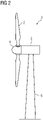
- the wind turbine blade handling tool 1 may be used for lifting a wind turbine blade 2, for instance during installation of a wind turbine 3 as schematically depicted in fig. 2 .
- the wind turbine 3 comprises a plurality of wind turbine blades 2, which are attached to a hub 4 of the wind turbine 1.
- the hub 4 is mounted to a nacelle 5 of the wind turbine 3, wherein the nacelle 5 is supported by a tower 6 of the wind turbine 3.
- the wind turbine blades 2 have to be lifted to the hub 4.
- a turning of the wind turbine blades 2 may be required to allow for attaching a root-side end of the blade 2 to the hub 4.
- the wind turbine handling tool 1 may be used for the lifting and/or the turning of the blade 2, for instance the wind turbine handling tool 1 may be used.
- the wind turbine blade handling tool 1 comprises two supporting segments 7, which each support a surface portion 8 of an outer surface 9 of the wind turbine blade 2.
- the handling tool 1 is a lifting yoke used for lifting the wind turbine blade 2.
- the supporting segments 7 are attached to a connecting segment 10, which may be attached to a hoist 11 for lifting of the wind turbine blade 2.
- the wind turbine blade 2 comprises a plurality of add-on elements 12, which are arranged in an area 13 of the outer surface 9 of the wind turbine blade 2. Also in the surface portions 8, which are supported on the supporting segments 7 of the wind turbine blade 1, add-on elements 12 are arranged.
- the add-on elements 12 may be for instance vanes 15 of one or more vortex generators 14.
- a vortex generator 14 is shown.
- the vortex generator 14 comprises a plurality of vanes 15 as aerodynamical add-on elements 12.
- the vanes 15 are attached to a base plate 16 of the vortex generator 14, wherein the vanes 15 protrude perpendicular from the base plate 16 and hence perpendicular from the outer surface 9 of the wind turbine blade 2.
- the vanes 15, or the aerodynamical add-on elements 12, respectively, each comprise a triangular fin-shape and enhance the aerodynamic properties of the wind turbine blade 2 during operation of the wind turbine 3.
- the surface portions 8 are supported on the supporting segment 7 of the handling tool 1, the vanes 15 are prone to be damaged during a handling procedure like the lifting of the wind turbine blade 2.
- the supporting segments 7 of the handling tool 1 each comprise at least one deformable protection pad 17, as it is depicted in the cross-sectional view of the handling tool 1 in fig. 4 .
- the surface portions 8 of the outer surface 9 of the wind turbine blade 2 are supported on the supporting segments 7 of the handling tool 1.
- the protection pad 17, which is arranged on the depicted supporting segment 7, is deformable in such manner that at least one blade add-on element 12 protruding from the supported surface portion 8 is completely accommodated in the deformed protection pad 17.
- vanes 15 of the vortex generators 14 are depicted, wherein the vanes 15 are completely accommodated in the deformed protection pad 17.
- the protection pads 17 the vanes 15 of the vortex generator 14 are protected during the handling procedure since they are fully encompassed by the deformed protection pad 17. This avoids the occurrence of damage to the vanes 15 and prevents in particular a deformation, a bending and/or a braking of the vanes 15 while transferring all forces through the supported surface portion 8.
- the protection pad 17 consists of an elastically deformable and/or a permanently deformable material.
- the protection pad 17 may consist of an expanded polymer material, in particular of polyurethane and/or polystyrene.
- a protection pad 17 made for example from a polyurethane foam may be elastically deformable, so that the protection pad 17 returns into its original shape once the supported wind turbine blade 2 has been removed from the handling tool 1 or vice versa.
- the protection pad 17 may be manufactured from expanded polystyrene (EPS), which is plastically deformed, or permanently deformed, respectively, when the wind turbine blade 2 is supported on the protection pad 17, or the supporting segment 7, respectively.
- EPS expanded polystyrene
- the vanes 15 of the vortex generator 14 may punch a hole, or a triangular slit, respectively, into the protection pad 17, when the surface portion 8 of the wind turbine blade 2 is supported on the supporting segment 7 of the handling tool 1.
- the protection pad 17 may be releasably attached to the supporting segment 17, so that it may be replaced after a plurality of handling procedures.
- the contact surface 18 of the supporting segments 7, which is directed to the supported surface portion 8 of the wind turbine blade 2 may be entirely or partly covered by one or more protection pads 17. In case that only a portion of the surface 18 of the supporting segment 7 is covered by one or more protection pads 17, it is possible that the one or more protection pads 17 are accommodated in at least one recess of the surface 18, so that the entire supported surface portion 8 of the wind turbine blade 2 may be supported on the supporting segment 7 and the deformable protection pads 17.
- the protection pad 17 has a thickness t between 10 mm and 150 mm, in particular between 40 mm and 100 mm.
- the thickness of the protection pad 17 refers to a state, in which the wind turbine blade 2 is not supported on the handling tool 1, since the protection pad 17 may be compressed during the handling of the wind turbine blade 2.
- the protection pad 17 consists of an expanded polymer
- the protection pad is comparatively soft so that a compression of the protection pad 17 may occur as part of the deformation when the wind turbine blade 2 is supported on the handling tool 1.
- the add-on elements 12, or the vanes 15 of the vortex generator 14, respectively are fully accommodated in the protection pad 17 also in the compressed state of the protection pad 17.
- the handling tool 1 is a wind turbine blade storage support element.
- the handling tool 1 comprises one supporting segment 7, which supports a surface portion 8 of a stored wind turbine blade 2.
- the handling tool 1 comprises two or more base segments 19, to which the supporting segment 7 is attached.
- the protection pad 17 is deformed in such manner that it accommodates one or more vanes 15 of the vortex generator 14 of the supported wind turbine blade 2.
- the handling tool 1 comprises other than the depicted structures and geometries. It is in particular possible that the handling tool 1 is a turning yoke, a clamp, a sling and/or a wind turbine blade fixture instead.
- other add-on elements 12 which protrude from the outer surface 9 of the wind turbine blade 2, may be accommodated in the deformed protection pad 17.
- a handling tool 1 for example according to one of the aforementioned embodiments, may be used.
- the protection pad 17 is arranged between the supporting segment 7 and the wind turbine blade 2, for instance by attaching the protection pad 17 to the supporting segment 7.
- the protection pad 17 is deformed in such manner that the blade add-on element 12 is completely accommodated in the deformed protection pad 17.
- the usage of the protection pad 17 for the blade handling and/or as part of the handling tool 1, respectively, reduces the risk of damaging the add-on elements 12 during base handling, in particular during lifting, turning, transportation, installation and/or storage of the wind turbine blade 2.
- the protection pad 17, or the plurality of protection pads 17, respectively, is able to handle the loads occurring during the blade handling process.
- the design of the wind turbine blade 2 is not constrained with regard to the positioning of the add-on elements 12, in particular of the vortex generators 14.
- an arrangement of the add-on elements 12 in one or more surface regions 8, which are used for supporting the wind turbine blade 2 during the handling procedures is possible. Therefore, the add-on elements 12 may be attached to the blade 2 in the optimal positions for obtaining the desired aerodynamic properties of the wind turbine blade 2 so that the wind turbine blade 2 may be operated with good efficiency in all conditions.
- the usage of the protection pad 17 facilitates the handling of the wind turbine blade 2, since no additional care needs to be taken during handling to avoid damage to the add-on elements 12, since they are protected by the protection pad 17.
- a blade handling operation like an installation of the blade can be conducted faster, since less time is required to take special care for avoiding the add-on elements 12 to be damaged. This reduces the installation time and avoids additional manpower spent on repairing damaged add-on elements 12, in particular of damaged vortex generator vanes 15. Furthermore, also an installation of the add-on elements 12 after mounting of the wind turbine blade 2 to the hub 4 of the wind turbine 3 may be avoided. This advantageously reduces the down time of the wind turbine 3, as well as the installation time and therefore reduces an energy production loss of the wind turbine 3.
Landscapes
- Engineering & Computer Science (AREA)
- Mechanical Engineering (AREA)
- Life Sciences & Earth Sciences (AREA)
- Sustainable Development (AREA)
- Sustainable Energy (AREA)
- Chemical & Material Sciences (AREA)
- Combustion & Propulsion (AREA)
- General Engineering & Computer Science (AREA)
- Wind Motors (AREA)
Abstract
Wind turbine blade handling tool comprising at least one supporting segment (7) for supporting a surface portion (8) of an outer surface (9) of the blade (2) during handling of the wind turbine blade (2), wherein the supporting segment (7) comprises at least one deformable protection pad (17), which is deformable in such manner that at least one blade add-on element (12) protruding from the supported surface portion (8) is completely accommodated in the deformed protection pad (17) .
Description
- The invention relates to a wind turbine blade handling tool comprising at least one supporting segment for supporting a surface portion of an outer surface of the blade during handling of the wind turbine blade. Furthermore, the invention relates to a method for handling of a wind turbine blade.
- Handling of wind turbine blades is a special challenge due to the size and the structure of the blades. Blade handling refers in particular to lifting, turning, transportation, installation and storage of wind turbine blades and may require the usage of wind turbine blade handling tools for various purposes.
- To enhance the aerodynamic properties of wind turbine blades, it is known to provide add-on elements to the outer surface of the wind turbine blade. It is desired to mount the add-on elements on the outer surface of the blade already during the production of the wind turbine blade in order to reduce the effort during installation of the wind turbine blade. However, since these add-on elements may protrude from the outer surface of the wind turbine blade, they are prone to be damaged during the subsequent handling of the wind turbine blade, in particular when they come into contact with a wind turbine blade handling tool used for the handling of the wind turbine blade.
- Several factors, such as increasing blade length, increasing blade mass, the development of blade designs and their accompanying aerodynamic add-on elements as well as changes in the methods used for orienting the wind turbine blades during handling, may cause conflicts between the handling equipment and the aerodynamic add-on elements more frequently in the future.
- Therefore, it is an object of the invention to provide an improved wind turbine blade handling tool, which avoids or at least reduces the risk of damaging a wind turbine blade add-on element during the handling of the blade.
- According to the invention, this object is solved by a wind turbine blade handling tool as initially described, wherein the supporting segment comprises at least one deformable protection pad, which is deformable in such manner that at least one blade add-on element protruding from the support surface portion is completely accommodated in the deformed protection pad.
- The wind turbine blade handling tool, which is denoted in the following also as handling tool, comprises at least one supporting segment. The supporting segment is used for supporting a surface portion of the outer surface of the wind turbine blade during handling of the blade. The handling tool can support the wind turbine blade with one or more supporting segments during blade handling, in particular during lifting, turning, transportation, installation and/or storage of the wind turbine blade.
- Since the supporting segment supports a part of the outer surface of the wind turbine blade, the wind turbine blade is in direct contact with the supporting segment. Due to the loads applied to the wind turbine blade during handling, an aerodynamic add-on element protruding from the supported surface portion may be damaged when it comes into contact with the supporting segment.
- By the at least one deformable protection pad of the supporting segment, it becomes possible that and add-on element protruding from the supported surface portion is completely accommodated in the deformed protection pad. The protection pad may deform for instance when the handling tool is coupled to the wind turbine blade at the beginning of a blade handling procedure, in particular when the wind turbine blade is supported on the wind turbine blade handling tool.
- The protection pad may be a soft pad and deforms in such manner that one or more add-on elements arranged in the supported surface portion of the wind turbine blade are accommodated in the deformed protection pad. In particular, a protruding add-on element may be fully encompassed and therefore entirely surrounded by the deformed protection pad when it is accommodated in the protection pad. This prevents that loads, which may cause a braking or an unintended bending of the add-on element, are induced into the add-on element. It is possible that the handling tool comprises a plurality of supporting segments, depending on the shape and/or the geometry of the handling tool. In this case, the one or more of the supporting segments may each comprise at least one protection pad.
- Preferably, the protection pad is deformable in such manner that at least one vane of a vortex generator is completely accommodated in the deformed protection pad. A vortex generator comprising one or more vanes as aerodynamic add-on elements may be used on a wind turbine blade for enhancing the aerodynamical properties of the blade. The vortex generator may consist of a flat base plate with a plurality of thin vanes, which protrude from the base plate and therefore also from the outer surface of the wind turbine blade, to which the base plate of the vortex generator is attached. These vanes or fins of the vortex generator may have a triangular or rectangular shape. Due to the comparatively thin geometry of the vanes and their perpendicular or essentially perpendicular orientation to the base plate, or the blade outer surface, respectively, they are inherently prone to deform, to bend, or to brake off once compressive and/or shear forces are applied to them. This may apply analogously to other types of add-on elements as well.
- The optimal positioning of aerodynamic add-on elements, in particular of vortex generators, on the outer surface of the wind turbine blade may depend on the size and the shape of the wind turbine blade. The areas, in which the maximum effect of aerodynamic add-on elements may be obtained, may overlap with one or more surface portions of the blade, which are used for blade handling and therefore supported on a supporting segment of a handling tool during blade handling. This may apply for instance to surface portions which are arranged opposite to a web structure or the like in the interior of the blade, since these surface portions may be suitable both for supporting the blade during handling and for arrangement of the add-on elements.
- By providing the protection pad on the supporting segment, it becomes possible to support a wind turbine blade also in a surface portion, in which aerodynamic add-on elements, for instance vortex generators or other types of add-on elements, have been arranged. This allows advantageously to handle wind turbine blades, which have aerodynamic add-on elements arranged also within the surface regions that are used during the blade handling procedures. In particular, the usage of the deformable protection pad allows advantageously for transferring all forces through the supported surface portion, since the at least one protection pad is able to take the loads during the handling procedure.
- In particular, this allows to use and to handle wind turbine blades with aerodynamic add-on elements arranged in the optimal positions, independently on whether they conflict with the surface portions used for blade handling or not. This has the advantage that the wind turbine blades may be designed aerodynamically more efficient and with a more robust aerodynamic performance.
- By avoiding damage to the at least one add-on element, repair procedures after the blade handling, in particular repair or exchange of damaged add-on elements, may be avoided. Such repair procedures tend to be tedious and comparatively costly, since they have to be conducted in a state, in which the wind turbine blade has already been mounted to the hub of a wind turbine.
- The usage of the at least one deformable protection pad on the supporting segment of the handling tool allows for installation of the add-on element already in the factory during the wind turbine blade fabrication, on the factory yard after the blade fabrication and/or prior to hoisting the blade for installation on a wind turbine blade. Therefore, also the installation process of the add-on elements is facilitated. Furthermore, also the blade handling procedures using the handling tool are facilitated, since less care has to be taken to avoid damaging the aerodynamic add-on elements of the handled wind turbine blade.
- In a preferred embodiment, the protection pad comprises a material, which is elastically deformable and/or permanently deformable by the add-on element of the supported surface portion. The protection pad may be elastically deformed when the wind turbine blade is supported on the supporting segment of the handling tool, or on the protection pad, respectively. The add-on element protruding from the surface may deform the protection pad elastically and/or plastically during arrangement of the handling tool on the wind turbine blade, so that the add-on element is completely accommodated in the deformed protection pad.
- Depending on the material used for the protection pad, it is possible that the protection pad is comparatively soft so that it is compressed when the wind turbine blade is supported on the handling tool. In this case, the add-on element, for example the vane of a vortex generator, is completely accommodated in the protection pad in the compressed state of the protection pad.
- The usage of an elastically deformable protection pad allows to reuse the protection pad in a plurality of blade handling procedures, since the protection pad returns at least partly in its original shape once the supported wind turbine blade has been removed from the supporting segment. However, it is also possible to use a permanently deformable protection pad, which is plastically deformed for accommodating the add-on element. It is in particular possible that an add-on element like a vane of a vortex generator punches a hole and/or a slit or the like into the protection pad when the wind turbine blade is supported on the handling tool. In this case, the number of usages of the protection pad is limited so that the protection pads are sacrificial elements which have to be exchanged after some blade handling procedures.
- Preferably, the protection pad consists of an expanded polymer material. The expanded polymer material may be for instance a solidified polymer foam. Depending on the structure of the material, it may be more or less compressible when a wind turbine blade is supported on the handling tool.
- Preferably, the protection pad consists of polyurethane and/or polystyrene. The usage of polyurethane and/or polystyrene allows the manufacturing of comparatively cheap and robust protection pads.
- In a preferred embodiment, the protection pad comprises a thickness between 10 mm and 150 mm, in particular between 40 mm and 100 mm. The thickness of the protection pad refers to the state, in which the wind turbine blade is not supported, since the material may be compressed during handling of the wind turbine blade as previously described. Such a thickness is in particular suitable to accommodate an add-on element like a vane of a vortex generator also in a compressed state of the protection pad. For example, the length of the vortex generator perpendicular to the outer surface of the wind turbine blade may be in the range of only a few centimeters and therefore smaller than the thickness of the protection pad in its compressed state.
- Preferably, the supporting segment is covered by the protection pad. By providing a supporting segment, which is covered by the protection pad, or by a plurality of protection pads, respectively, the coupling between the handling tool and the wind turbine blade is facilitated since the add-on element may be protected all over the supporting segment. In particular, the at least one protection pad is arranged in such manner that it covers at least the entire contact surface of the supporting segment, which comes into direct contact with the wind turbine blade during blade handling.
- In a preferred embodiment, the protection pad is releasably attached on the supporting segment. This facilitates an exchange of the protection pad, for instance when it has been deformed plastically several times.
- In a preferred embodiment of the invention, the wind turbine blade handling tool is a lifting yoke, a turning yoke, a clamp, a sling, a wind turbine blade fixture and/or a wind turbine blade storage support element. The wind turbine blade handling tool may comprise for instance a clamp-shape, in which two or more supporting segments encompass at least a portion of the outer circumference of the wind turbine blade. In this case, one or more of the supporting segments may comprise at least one protection pad.
- In a method according to the invention for handling of a wind turbine blade comprising at least one blade add-on element protruding from a surface portion of an outer surface of the blade, a wind turbine blade handling tool comprising a supporting segment for supporting the surface portion of the blades during handling is used, wherein a protection pad is arranged on the supporting segment, wherein the protection pad is deformed in such manner that the blade add-on element is completely accommodated in the deformed protection pad. The protection pad used for accommodating the add-on element may be attached to the supporting segment of the blade handling tool or it may be arranged in between the supporting segment for supporting the wind turbine blade on the handling tool. It is in particular possible that a wind turbine blade handling tool according to the invention is used in the method according to the invention for handling of a wind turbine blade.
- All details and advantages described in relation to the wind turbine blade handling tool apply correspondingly to the method for handling of a wind turbine blade and vice versa.
- Other objects and features of the present invention will become apparent from the following detailed description considered in conjunction with the accompanying drawings. The drawings, however, are only principle sketches designed solely for the purpose of illustration and do not limit the invention. The drawings show:
- Fig. 1
- a first embodiment of a wind turbine blade handling tool according to the invention,
- Fig. 2
- a schematical depiction of a wind turbine,
- Fig. 3
- a vortex generator of a wind turbine blade,
- Fig. 4
- a cross-sectional view of the first embodiment of the wind turbine blade handling tool according to the invention, and
- Fig. 5
- a second embodiment of a wind turbine blade handling tool according to the invention.
- In
fig. 1 , an embodiment of a wind turbineblade handling tool 1 is shown. The wind turbineblade handling tool 1 may be used for lifting awind turbine blade 2, for instance during installation of awind turbine 3 as schematically depicted infig. 2 . Thewind turbine 3 comprises a plurality ofwind turbine blades 2, which are attached to ahub 4 of thewind turbine 1. Thehub 4 is mounted to anacelle 5 of thewind turbine 3, wherein thenacelle 5 is supported by atower 6 of thewind turbine 3. During installation of thewind turbine 3, thewind turbine blades 2 have to be lifted to thehub 4. In addition to the lifting, also a turning of thewind turbine blades 2 may be required to allow for attaching a root-side end of theblade 2 to thehub 4. For the lifting and/or the turning of theblade 2, for instance the windturbine handling tool 1 may be used. - As can be seen in
fig. 1 , the wind turbineblade handling tool 1 comprises two supportingsegments 7, which each support asurface portion 8 of anouter surface 9 of thewind turbine blade 2. In this embodiment, thehandling tool 1 is a lifting yoke used for lifting thewind turbine blade 2. The supportingsegments 7 are attached to a connectingsegment 10, which may be attached to a hoist 11 for lifting of thewind turbine blade 2. - The
wind turbine blade 2 comprises a plurality of add-onelements 12, which are arranged in anarea 13 of theouter surface 9 of thewind turbine blade 2. Also in thesurface portions 8, which are supported on the supportingsegments 7 of thewind turbine blade 1, add-onelements 12 are arranged. The add-onelements 12 may be forinstance vanes 15 of one ormore vortex generators 14. - In
fig. 3 , avortex generator 14 is shown. Thevortex generator 14 comprises a plurality ofvanes 15 as aerodynamical add-onelements 12. Thevanes 15 are attached to abase plate 16 of thevortex generator 14, wherein thevanes 15 protrude perpendicular from thebase plate 16 and hence perpendicular from theouter surface 9 of thewind turbine blade 2. Thevanes 15, or the aerodynamical add-onelements 12, respectively, each comprise a triangular fin-shape and enhance the aerodynamic properties of thewind turbine blade 2 during operation of thewind turbine 3. However, since thesurface portions 8 are supported on the supportingsegment 7 of thehandling tool 1, thevanes 15 are prone to be damaged during a handling procedure like the lifting of thewind turbine blade 2. - Therefore, the supporting
segments 7 of thehandling tool 1 each comprise at least onedeformable protection pad 17, as it is depicted in the cross-sectional view of thehandling tool 1 infig. 4 . Thesurface portions 8 of theouter surface 9 of thewind turbine blade 2 are supported on the supportingsegments 7 of thehandling tool 1. Theprotection pad 17, which is arranged on the depicted supportingsegment 7, is deformable in such manner that at least one blade add-onelement 12 protruding from the supportedsurface portion 8 is completely accommodated in thedeformed protection pad 17. - In this embodiment, two
vanes 15 of thevortex generators 14 are depicted, wherein thevanes 15 are completely accommodated in thedeformed protection pad 17. By theprotection pads 17, thevanes 15 of thevortex generator 14 are protected during the handling procedure since they are fully encompassed by thedeformed protection pad 17. This avoids the occurrence of damage to thevanes 15 and prevents in particular a deformation, a bending and/or a braking of thevanes 15 while transferring all forces through the supportedsurface portion 8. - The
protection pad 17 consists of an elastically deformable and/or a permanently deformable material. For instance, theprotection pad 17 may consist of an expanded polymer material, in particular of polyurethane and/or polystyrene. Aprotection pad 17 made for example from a polyurethane foam may be elastically deformable, so that theprotection pad 17 returns into its original shape once the supportedwind turbine blade 2 has been removed from thehandling tool 1 or vice versa. - In an alternative, the
protection pad 17 may be manufactured from expanded polystyrene (EPS), which is plastically deformed, or permanently deformed, respectively, when thewind turbine blade 2 is supported on theprotection pad 17, or the supportingsegment 7, respectively. In this case, thevanes 15 of thevortex generator 14 may punch a hole, or a triangular slit, respectively, into theprotection pad 17, when thesurface portion 8 of thewind turbine blade 2 is supported on the supportingsegment 7 of thehandling tool 1. - The
protection pad 17 may be releasably attached to the supportingsegment 17, so that it may be replaced after a plurality of handling procedures. The contact surface 18 of the supportingsegments 7, which is directed to the supportedsurface portion 8 of thewind turbine blade 2, may be entirely or partly covered by one ormore protection pads 17. In case that only a portion of the surface 18 of the supportingsegment 7 is covered by one ormore protection pads 17, it is possible that the one ormore protection pads 17 are accommodated in at least one recess of the surface 18, so that the entire supportedsurface portion 8 of thewind turbine blade 2 may be supported on the supportingsegment 7 and thedeformable protection pads 17. - The
protection pad 17 has a thickness t between 10 mm and 150 mm, in particular between 40 mm and 100 mm. The thickness of theprotection pad 17 refers to a state, in which thewind turbine blade 2 is not supported on thehandling tool 1, since theprotection pad 17 may be compressed during the handling of thewind turbine blade 2. In particular, when theprotection pad 17 consists of an expanded polymer, the protection pad is comparatively soft so that a compression of theprotection pad 17 may occur as part of the deformation when thewind turbine blade 2 is supported on thehandling tool 1. In this case, the add-onelements 12, or thevanes 15 of thevortex generator 14, respectively, are fully accommodated in theprotection pad 17 also in the compressed state of theprotection pad 17. - In
fig. 5 , a second embodiment of the wind turbineblade handling tool 1 is shown. In this embodiment, thehandling tool 1 is a wind turbine blade storage support element. Thehandling tool 1 comprises one supportingsegment 7, which supports asurface portion 8 of a storedwind turbine blade 2. In addition to the supportingsegment 7, thehandling tool 1 comprises two ormore base segments 19, to which the supportingsegment 7 is attached. Theprotection pad 17 is deformed in such manner that it accommodates one ormore vanes 15 of thevortex generator 14 of the supportedwind turbine blade 2. - The depictions in the figures are only schematically and in particular not drawn to scale. It is possible that the
handling tool 1 comprises other than the depicted structures and geometries. It is in particular possible that thehandling tool 1 is a turning yoke, a clamp, a sling and/or a wind turbine blade fixture instead. In addition or alternatively to the describedvanes 15 of thevortex generator 14, other add-onelements 12, which protrude from theouter surface 9 of thewind turbine blade 2, may be accommodated in thedeformed protection pad 17. - In an embodiment of a method for handling of a
wind turbine blade 2 comprising at least one blade add-onelement 12 protruding from asurface portion 8 of anouter surface 9 of theblade 2, ahandling tool 1, for example according to one of the aforementioned embodiments, may be used. Theprotection pad 17 is arranged between the supportingsegment 7 and thewind turbine blade 2, for instance by attaching theprotection pad 17 to the supportingsegment 7. When thewind turbine blade 2 is supported on thehandling tool 1, or when thesurface portion 8 of the blade is supported on the supportingsegment 7, or theprotection pad 17, respectively, theprotection pad 17 is deformed in such manner that the blade add-onelement 12 is completely accommodated in thedeformed protection pad 17. - The usage of the
protection pad 17 for the blade handling and/or as part of thehandling tool 1, respectively, reduces the risk of damaging the add-onelements 12 during base handling, in particular during lifting, turning, transportation, installation and/or storage of thewind turbine blade 2. Theprotection pad 17, or the plurality ofprotection pads 17, respectively, is able to handle the loads occurring during the blade handling process. - Furthermore, the design of the
wind turbine blade 2 is not constrained with regard to the positioning of the add-onelements 12, in particular of thevortex generators 14. In particular, an arrangement of the add-onelements 12 in one ormore surface regions 8, which are used for supporting thewind turbine blade 2 during the handling procedures, is possible. Therefore, the add-onelements 12 may be attached to theblade 2 in the optimal positions for obtaining the desired aerodynamic properties of thewind turbine blade 2 so that thewind turbine blade 2 may be operated with good efficiency in all conditions. The usage of theprotection pad 17 facilitates the handling of thewind turbine blade 2, since no additional care needs to be taken during handling to avoid damage to the add-onelements 12, since they are protected by theprotection pad 17. - In particular, a blade handling operation like an installation of the blade can be conducted faster, since less time is required to take special care for avoiding the add-on
elements 12 to be damaged. This reduces the installation time and avoids additional manpower spent on repairing damaged add-onelements 12, in particular of damaged vortex generator vanes 15. Furthermore, also an installation of the add-onelements 12 after mounting of thewind turbine blade 2 to thehub 4 of thewind turbine 3 may be avoided. This advantageously reduces the down time of thewind turbine 3, as well as the installation time and therefore reduces an energy production loss of thewind turbine 3. - Although the present invention has been described in detail with reference to the preferred embodiment, the present invention is not limited by the disclosed examples from which the skilled person is able to derive other variations without departing from the scope of the invention.
Claims (10)
- Wind turbine blade handling tool comprising at least one supporting segment (7) for supporting a surface portion (8) of an outer surface (9) of the blade (2) during handling of the wind turbine blade (2), wherein the supporting segment (7) comprises at least one deformable protection pad (17), which is deformable in such manner that at least one blade add-on element (12) protruding from the supported surface portion (8) is completely accommodated in the deformed protection pad (17).
- Wind turbine blade handling tool according to claim 1, characterized in that the protection pad (17) comprises a material, which is elastically deformable and/or permanently deformable by the add-on element (12) of the supported surface portion (8).
- Wind turbine blade handling tool according to claim 1 or 2, characterized in that the protection pad (17) consists of an expanded polymer material.
- Wind turbine blade handling tool according to claim 3, characterized in that the protection pad (17) consists of polyurethane and/or polystyrene.
- Wind turbine blade handling tool according to one of the preceding claims, characterized in that the protection pad (17) comprises a thickness between 10mm and 150mm, in particular between 40mm and 100mm.
- Wind turbine blade handling tool according to one of the preceding claims, characterized in that the supporting segment (7) is covered by the protection pad (17).
- Wind turbine blade handling tool according to one of the preceding claims, characterized in that the protection pad (17) is releasably attached on the supporting segment (7) .
- Wind turbine blade handling tool according to one of the preceding claims, characterized in that the protection pad (17) is deformable in such manner that at least one vane (15) of a vortex generator (14) is completely accommodated in the deformed protection pad (17).
- Wind turbine blade handling tool according to one of the preceding claims, characterized in that the wind turbine blade handling tool (1) is a lifting yoke, a turning yoke, a clamp, a sling, a wind turbine blade fixture and/or a wind turbine blade storage support element.
- Method for handling of a wind turbine blade (2) comprising at least one blade add-on element (12) protruding from a surface portion (8) of an outer surface (9) of the blade (2), wherein a wind turbine blade handling tool (1) comprising a supporting segment (7) for supporting the surface portion (17) of the blade (2) during handling is used, wherein a protection pad (17) is arranged on the supporting segment (7), wherein the protection pad (17) is deformed in such manner that the blade add-on element (12) is completely accommodated in the deformed protection pad (17).
Priority Applications (5)
| Application Number | Priority Date | Filing Date | Title |
|---|---|---|---|
| EP21177752.9A EP4098866A1 (en) | 2021-06-04 | 2021-06-04 | Wind turbine blade handling tool and method for handling of a wind turbine blade |
| US18/565,048 US20240279030A1 (en) | 2021-06-04 | 2022-05-11 | Wind turbine blade handling tool and method for handling of a wind turbine blade |
| PCT/EP2022/062826 WO2022253539A1 (en) | 2021-06-04 | 2022-05-11 | Wind turbine blade handling tool and method for handling of a wind turbine blade |
| EP22728598.8A EP4314548A1 (en) | 2021-06-04 | 2022-05-11 | Wind turbine blade handling tool and method for handling of a wind turbine blade |
| CN202280040081.0A CN117425775A (en) | 2021-06-04 | 2022-05-11 | Wind turbine blade manipulation tool and method for maneuvering wind turbine blades |
Applications Claiming Priority (1)
| Application Number | Priority Date | Filing Date | Title |
|---|---|---|---|
| EP21177752.9A EP4098866A1 (en) | 2021-06-04 | 2021-06-04 | Wind turbine blade handling tool and method for handling of a wind turbine blade |
Publications (1)
| Publication Number | Publication Date |
|---|---|
| EP4098866A1 true EP4098866A1 (en) | 2022-12-07 |
Family
ID=76283607
Family Applications (2)
| Application Number | Title | Priority Date | Filing Date |
|---|---|---|---|
| EP21177752.9A Withdrawn EP4098866A1 (en) | 2021-06-04 | 2021-06-04 | Wind turbine blade handling tool and method for handling of a wind turbine blade |
| EP22728598.8A Pending EP4314548A1 (en) | 2021-06-04 | 2022-05-11 | Wind turbine blade handling tool and method for handling of a wind turbine blade |
Family Applications After (1)
| Application Number | Title | Priority Date | Filing Date |
|---|---|---|---|
| EP22728598.8A Pending EP4314548A1 (en) | 2021-06-04 | 2022-05-11 | Wind turbine blade handling tool and method for handling of a wind turbine blade |
Country Status (4)
| Country | Link |
|---|---|
| US (1) | US20240279030A1 (en) |
| EP (2) | EP4098866A1 (en) |
| CN (1) | CN117425775A (en) |
| WO (1) | WO2022253539A1 (en) |
Citations (4)
| Publication number | Priority date | Publication date | Assignee | Title |
|---|---|---|---|---|
| US20150329036A1 (en) * | 2014-05-14 | 2015-11-19 | General Electric Company | Transportation assembly for rotor blade |
| US20180195497A1 (en) * | 2017-05-30 | 2018-07-12 | General Electric Company | Handling device for a wind turbine rotor blade having a moldable support pad |
| DE102018004152A1 (en) * | 2018-05-23 | 2019-11-28 | Senvion Gmbh | Lifting system for a rotor blade and method for lifting a rotor blade |
| EP3792211A1 (en) * | 2019-09-16 | 2021-03-17 | Siemens Gamesa Renewable Energy A/S | Lifting tool for lifting a wind turbine blade, lifting arrangement, wind turbine installation system and method for assembling a wind turbine blade with a hub of a wind turbine |
-
2021
- 2021-06-04 EP EP21177752.9A patent/EP4098866A1/en not_active Withdrawn
-
2022
- 2022-05-11 WO PCT/EP2022/062826 patent/WO2022253539A1/en not_active Ceased
- 2022-05-11 CN CN202280040081.0A patent/CN117425775A/en active Pending
- 2022-05-11 US US18/565,048 patent/US20240279030A1/en active Pending
- 2022-05-11 EP EP22728598.8A patent/EP4314548A1/en active Pending
Patent Citations (4)
| Publication number | Priority date | Publication date | Assignee | Title |
|---|---|---|---|---|
| US20150329036A1 (en) * | 2014-05-14 | 2015-11-19 | General Electric Company | Transportation assembly for rotor blade |
| US20180195497A1 (en) * | 2017-05-30 | 2018-07-12 | General Electric Company | Handling device for a wind turbine rotor blade having a moldable support pad |
| DE102018004152A1 (en) * | 2018-05-23 | 2019-11-28 | Senvion Gmbh | Lifting system for a rotor blade and method for lifting a rotor blade |
| EP3792211A1 (en) * | 2019-09-16 | 2021-03-17 | Siemens Gamesa Renewable Energy A/S | Lifting tool for lifting a wind turbine blade, lifting arrangement, wind turbine installation system and method for assembling a wind turbine blade with a hub of a wind turbine |
Also Published As
| Publication number | Publication date |
|---|---|
| US20240279030A1 (en) | 2024-08-22 |
| EP4314548A1 (en) | 2024-02-07 |
| CN117425775A (en) | 2024-01-19 |
| WO2022253539A1 (en) | 2022-12-08 |
Similar Documents
| Publication | Publication Date | Title |
|---|---|---|
| US20180195497A1 (en) | Handling device for a wind turbine rotor blade having a moldable support pad | |
| EP2794455B1 (en) | Method and apparatus for handling wind turbine components during transport and assembly | |
| EP2525092B1 (en) | Wind turbine blade lifting element and method followed | |
| EP2712718B1 (en) | Method for forming a rotor blade | |
| US20170218915A1 (en) | Lifting Device for a Wind Turbine Rotor Blade | |
| JP6851752B2 (en) | Positioning system between members, positioning method between members, joining system of members, joining method of members, and joining method of offshore structures | |
| EP1748182A2 (en) | Method and apparatus for replacing objects mounted on horizontal shafts in elevated locations | |
| CA3084236C (en) | Wind turbine and method for assembling a wind turbine | |
| EP2434152A2 (en) | Installation for assembling composite material structures | |
| WO2020216420A1 (en) | A nacelle of a wind turbine | |
| CN114658592A (en) | Method of mounting or dismounting a blade to or from a rotor hub of a wind turbine | |
| US20240279030A1 (en) | Wind turbine blade handling tool and method for handling of a wind turbine blade | |
| EP2927478B1 (en) | Installing a blade in a wind turbine and wind turbines | |
| US20190136626A1 (en) | External ladder assembly for wind turbine nacelle | |
| CN103527397A (en) | Compressing element applied to rotor blade of wind driven generator | |
| CN205933056U (en) | Large -scale barrel shipment equipment | |
| JP5663249B2 (en) | Blade lifting method and blade lifting jig of wind power generator | |
| CN114087140B (en) | Integrated system and method for maintaining components of wind turbines | |
| EP4212717B1 (en) | A trailing edge protector for a wind turbine rotor blade | |
| EP4353965A1 (en) | Method of disassembling a segmented blade for a wind turbine | |
| CN213056071U (en) | Connection tooling for web assemblies and wind turbine blades | |
| CN109424194A (en) | Purlin for tower pouring construction | |
| EP4652368A1 (en) | Guiding systems for wind turbine blade components | |
| KR101769003B1 (en) | Apparatus and method for lifting the rotor pole of generator |
Legal Events
| Date | Code | Title | Description |
|---|---|---|---|
| PUAI | Public reference made under article 153(3) epc to a published international application that has entered the european phase |
Free format text: ORIGINAL CODE: 0009012 |
|
| STAA | Information on the status of an ep patent application or granted ep patent |
Free format text: STATUS: THE APPLICATION HAS BEEN PUBLISHED |
|
| AK | Designated contracting states |
Kind code of ref document: A1 Designated state(s): AL AT BE BG CH CY CZ DE DK EE ES FI FR GB GR HR HU IE IS IT LI LT LU LV MC MK MT NL NO PL PT RO RS SE SI SK SM TR |
|
| STAA | Information on the status of an ep patent application or granted ep patent |
Free format text: STATUS: THE APPLICATION IS DEEMED TO BE WITHDRAWN |
|
| 18D | Application deemed to be withdrawn |
Effective date: 20230608 |