EP4098844A1 - Hybrid platform manufacturing - Google Patents
Hybrid platform manufacturing Download PDFInfo
- Publication number
- EP4098844A1 EP4098844A1 EP22175957.4A EP22175957A EP4098844A1 EP 4098844 A1 EP4098844 A1 EP 4098844A1 EP 22175957 A EP22175957 A EP 22175957A EP 4098844 A1 EP4098844 A1 EP 4098844A1
- Authority
- EP
- European Patent Office
- Prior art keywords
- portions
- require
- platform
- cmc
- thickness
- Prior art date
- Legal status (The legal status is an assumption and is not a legal conclusion. Google has not performed a legal analysis and makes no representation as to the accuracy of the status listed.)
- Pending
Links
- 238000004519 manufacturing process Methods 0.000 title description 5
- 239000011153 ceramic matrix composite Substances 0.000 claims abstract description 54
- 238000000034 method Methods 0.000 claims abstract description 33
- 238000000626 liquid-phase infiltration Methods 0.000 claims abstract description 28
- 238000001764 infiltration Methods 0.000 claims abstract description 9
- 230000008595 infiltration Effects 0.000 claims abstract description 9
- 239000000126 substance Substances 0.000 claims abstract description 9
- 238000012545 processing Methods 0.000 description 5
- 230000008901 benefit Effects 0.000 description 4
- 239000000446 fuel Substances 0.000 description 4
- 230000008569 process Effects 0.000 description 4
- 230000003068 static effect Effects 0.000 description 3
- 238000010586 diagram Methods 0.000 description 2
- 239000012530 fluid Substances 0.000 description 2
- 239000000463 material Substances 0.000 description 2
- 238000012986 modification Methods 0.000 description 2
- 230000004048 modification Effects 0.000 description 2
- 230000009467 reduction Effects 0.000 description 2
- 230000015572 biosynthetic process Effects 0.000 description 1
- 230000008859 change Effects 0.000 description 1
- 239000011248 coating agent Substances 0.000 description 1
- 238000000576 coating method Methods 0.000 description 1
- 238000004891 communication Methods 0.000 description 1
- 230000006835 compression Effects 0.000 description 1
- 238000007906 compression Methods 0.000 description 1
- 238000010276 construction Methods 0.000 description 1
- 238000012937 correction Methods 0.000 description 1
- 230000000694 effects Effects 0.000 description 1
- 230000007246 mechanism Effects 0.000 description 1
- 230000004044 response Effects 0.000 description 1
Images


Classifications
-
- F—MECHANICAL ENGINEERING; LIGHTING; HEATING; WEAPONS; BLASTING
- F01—MACHINES OR ENGINES IN GENERAL; ENGINE PLANTS IN GENERAL; STEAM ENGINES
- F01D—NON-POSITIVE DISPLACEMENT MACHINES OR ENGINES, e.g. STEAM TURBINES
- F01D5/00—Blades; Blade-carrying members; Heating, heat-insulating, cooling or antivibration means on the blades or the members
- F01D5/12—Blades
- F01D5/28—Selecting particular materials; Particular measures relating thereto; Measures against erosion or corrosion
- F01D5/282—Selecting composite materials, e.g. blades with reinforcing filaments
-
- F—MECHANICAL ENGINEERING; LIGHTING; HEATING; WEAPONS; BLASTING
- F01—MACHINES OR ENGINES IN GENERAL; ENGINE PLANTS IN GENERAL; STEAM ENGINES
- F01D—NON-POSITIVE DISPLACEMENT MACHINES OR ENGINES, e.g. STEAM TURBINES
- F01D5/00—Blades; Blade-carrying members; Heating, heat-insulating, cooling or antivibration means on the blades or the members
- F01D5/12—Blades
- F01D5/28—Selecting particular materials; Particular measures relating thereto; Measures against erosion or corrosion
- F01D5/284—Selection of ceramic materials
-
- F—MECHANICAL ENGINEERING; LIGHTING; HEATING; WEAPONS; BLASTING
- F01—MACHINES OR ENGINES IN GENERAL; ENGINE PLANTS IN GENERAL; STEAM ENGINES
- F01D—NON-POSITIVE DISPLACEMENT MACHINES OR ENGINES, e.g. STEAM TURBINES
- F01D9/00—Stators
- F01D9/02—Nozzles; Nozzle boxes; Stator blades; Guide conduits, e.g. individual nozzles
- F01D9/04—Nozzles; Nozzle boxes; Stator blades; Guide conduits, e.g. individual nozzles forming ring or sector
- F01D9/041—Nozzles; Nozzle boxes; Stator blades; Guide conduits, e.g. individual nozzles forming ring or sector using blades
-
- F—MECHANICAL ENGINEERING; LIGHTING; HEATING; WEAPONS; BLASTING
- F05—INDEXING SCHEMES RELATING TO ENGINES OR PUMPS IN VARIOUS SUBCLASSES OF CLASSES F01-F04
- F05D—INDEXING SCHEME FOR ASPECTS RELATING TO NON-POSITIVE-DISPLACEMENT MACHINES OR ENGINES, GAS-TURBINES OR JET-PROPULSION PLANTS
- F05D2220/00—Application
- F05D2220/30—Application in turbines
- F05D2220/32—Application in turbines in gas turbines
-
- F—MECHANICAL ENGINEERING; LIGHTING; HEATING; WEAPONS; BLASTING
- F05—INDEXING SCHEMES RELATING TO ENGINES OR PUMPS IN VARIOUS SUBCLASSES OF CLASSES F01-F04
- F05D—INDEXING SCHEME FOR ASPECTS RELATING TO NON-POSITIVE-DISPLACEMENT MACHINES OR ENGINES, GAS-TURBINES OR JET-PROPULSION PLANTS
- F05D2230/00—Manufacture
- F05D2230/30—Manufacture with deposition of material
- F05D2230/31—Layer deposition
-
- F—MECHANICAL ENGINEERING; LIGHTING; HEATING; WEAPONS; BLASTING
- F05—INDEXING SCHEMES RELATING TO ENGINES OR PUMPS IN VARIOUS SUBCLASSES OF CLASSES F01-F04
- F05D—INDEXING SCHEME FOR ASPECTS RELATING TO NON-POSITIVE-DISPLACEMENT MACHINES OR ENGINES, GAS-TURBINES OR JET-PROPULSION PLANTS
- F05D2230/00—Manufacture
- F05D2230/60—Assembly methods
-
- F—MECHANICAL ENGINEERING; LIGHTING; HEATING; WEAPONS; BLASTING
- F05—INDEXING SCHEMES RELATING TO ENGINES OR PUMPS IN VARIOUS SUBCLASSES OF CLASSES F01-F04
- F05D—INDEXING SCHEME FOR ASPECTS RELATING TO NON-POSITIVE-DISPLACEMENT MACHINES OR ENGINES, GAS-TURBINES OR JET-PROPULSION PLANTS
- F05D2240/00—Components
- F05D2240/10—Stators
- F05D2240/12—Fluid guiding means, e.g. vanes
-
- F—MECHANICAL ENGINEERING; LIGHTING; HEATING; WEAPONS; BLASTING
- F05—INDEXING SCHEMES RELATING TO ENGINES OR PUMPS IN VARIOUS SUBCLASSES OF CLASSES F01-F04
- F05D—INDEXING SCHEME FOR ASPECTS RELATING TO NON-POSITIVE-DISPLACEMENT MACHINES OR ENGINES, GAS-TURBINES OR JET-PROPULSION PLANTS
- F05D2240/00—Components
- F05D2240/20—Rotors
- F05D2240/30—Characteristics of rotor blades, i.e. of any element transforming dynamic fluid energy to or from rotational energy and being attached to a rotor
-
- F—MECHANICAL ENGINEERING; LIGHTING; HEATING; WEAPONS; BLASTING
- F05—INDEXING SCHEMES RELATING TO ENGINES OR PUMPS IN VARIOUS SUBCLASSES OF CLASSES F01-F04
- F05D—INDEXING SCHEME FOR ASPECTS RELATING TO NON-POSITIVE-DISPLACEMENT MACHINES OR ENGINES, GAS-TURBINES OR JET-PROPULSION PLANTS
- F05D2240/00—Components
- F05D2240/80—Platforms for stationary or moving blades
-
- F—MECHANICAL ENGINEERING; LIGHTING; HEATING; WEAPONS; BLASTING
- F05—INDEXING SCHEMES RELATING TO ENGINES OR PUMPS IN VARIOUS SUBCLASSES OF CLASSES F01-F04
- F05D—INDEXING SCHEME FOR ASPECTS RELATING TO NON-POSITIVE-DISPLACEMENT MACHINES OR ENGINES, GAS-TURBINES OR JET-PROPULSION PLANTS
- F05D2300/00—Materials; Properties thereof
- F05D2300/60—Properties or characteristics given to material by treatment or manufacturing
- F05D2300/603—Composites; e.g. fibre-reinforced
- F05D2300/6033—Ceramic matrix composites [CMC]
Definitions
- the present disclosure relates to the formation of certain gas turbine engine components and, more particularly, to a hybrid platform manufacturing method for gas turbine engine components.
- CMC ceramic matrix composite
- IFC interface coating
- CVI chemical vapor infiltration
- the CMC part creation process can include a leveraging of melt infiltration (MI) processing by creating MI processed platform flange inserts. It is often the goal to manage these and other stages in multiple phases as such management tends to create better CMC parts.
- CMC parts that are formed by way of CVI tend to be porous, with voids and cavities that lead to less thermal conductivity.
- a method of assembling a ceramic matrix composite (CMC) component includes assessing which portions of the CMC component require relatively high-temperature capability and which portions require at least one of strength, thickness and increased thermal conductivity, making the portions that require the relatively high temperature capability with chemical vapor infiltration (CVI), making the portions that require the at least one of strength, thickness and increased thermal conductivity with melt infiltration (MI) and combining the portions that require the relatively high temperature capability with the CVI and the portions that require the at least one of strength, thickness and increased thermal conductivity with the MI.
- CVI chemical vapor infiltration
- MI melt infiltration
- the CMC component includes a turbine blade or vane.
- the turbine blade or vane includes a platform and an airfoil section.
- the portions that require the relatively high temperature capability include the airfoil section.
- the portions that require the relatively high temperature capability include external parts of the platform and the portions that require the at least one of strength, thickness and increased thermal conductivity include internal parts of the platform.
- the external parts of the platform include gas path facing surfaces.
- the gas path facing surfaces have a minimum thickness of about 0.005 inches (0.0127 mm).
- the internal parts of the platform include radial flanges.
- the internal parts of the platform are T-shaped.
- the combining includes mechanically fitting together the portions that require the relatively high temperature capability and the portions that require the at least one of strength, thickness and increased thermal conductivity.
- the combining includes sliding the portions that require the at least one of strength, thickness and increased thermal conductivity into the portions that require the relatively high temperature capability.
- a method of assembling a ceramic matrix composite (CMC) turbine blade or vane includes forming internal parts of a platform using melt infiltration (MI), forming external parts of the platform and an airfoil section using chemical vapor infiltration (CVI) and mechanically fitting the internal parts of the platform with the external parts of the platform.
- MI melt infiltration
- CVI chemical vapor infiltration
- the external parts of the platform include gas path facing surfaces.
- the gas path facing surfaces have a minimum thickness of about 0.005 inches (0.0127 mm).
- the internal parts of the platform include radial flanges.
- the internal parts of the platform are T-shaped.
- the internal parts of the platform are slidable relative to the external parts of the platform.
- a ceramic matrix composite (CMC) turbine blade or vane includes a platform including external parts and internal parts mechanically fit with the external parts and an airfoil section disposed with the platform.
- the external parts of the platform and the airfoil section are formed from chemical vapor infiltration (CVI) and the internal parts of the platform are formed from melt infiltration (MI).
- the external parts of the platform include gas path facing surfaces having a minimum thickness of about 0.005 inches (0.0127 mm).
- the internal parts of the platform are T-shaped and include radial flanges.
- CMC parts formed with CVI can exhibit limitations on cold side features where added thickness for strength is often needed.
- CMC parts with flanges that carry vane aerodynamic loads are especially difficult to manufacture with CVI and achieve structural needs.
- a CMC component is manufactured in a piecemeal manner with CVI and MI portions where the CVI portions are built in different manners from the MI portions.
- the airfoil portion of a vane and certain portions of platforms could be made via CVI but other portions of the platforms would be made with MI. This hybrid scheme will reap the benefits of each process for maximum CMC component capability.
- FIG. 1 schematically illustrates a gas turbine engine 20.
- the gas turbine engine 20 is disclosed herein as a two-spool turbofan that generally incorporates a fan section 22, a compressor section 24, a combustor section 26 and a turbine section 28.
- Alternative engines might include other systems or features.
- the fan section 22 drives air along a bypass flow path B in a bypass duct, while the compressor section 24 drives air along a core flow path C for compression and communication into the combustor section 26 then expansion through the turbine section 28.
- FIG. 1 schematically illustrates a gas turbine engine 20.
- the gas turbine engine 20 is disclosed herein as a two-spool turbofan that generally incorporates a fan section 22, a compressor section 24, a combustor section 26 and a turbine section 28.
- Alternative engines might include other systems or features.
- the fan section 22 drives air along a bypass flow path B in a bypass duct
- the compressor section 24 drives air along a core flow path C for compression and communication into the combustor section 26
- the exemplary engine 20 generally includes a low speed spool 30 and a high speed spool 32 mounted for rotation about an engine central longitudinal axis A relative to an engine static structure 36 via several bearing systems 38. It should be understood that various bearing systems 38 at various locations may alternatively or additionally be provided, and the location of bearing systems 38 may be varied as appropriate to the application.
- the low speed spool 30 generally includes an inner shaft 40 that interconnects a fan 42, a low pressure compressor 44 and a low pressure turbine 46.
- the inner shaft 40 is connected to the fan 42 through a speed change mechanism, which in exemplary gas turbine engine 20 is illustrated as a geared architecture 48 to drive the fan 42 at a lower speed than the low speed spool 30.
- the high speed spool 32 includes an outer shaft 50 that interconnects a high pressure compressor 52 and high pressure turbine 54.
- a combustor 56 is arranged in exemplary gas turbine 20 between the high pressure compressor 52 and the high pressure turbine 54.
- An engine static structure 36 is arranged generally between the high pressure turbine 54 and the low pressure turbine 46.
- the engine static structure 36 further supports bearing systems 38 in the turbine section 28.
- the inner shaft 40 and the outer shaft 50 are concentric and rotate via bearing systems 38 about the engine central longitudinal axis A which is collinear with their longitudinal axes.
- each of the positions of the fan section 22, compressor section 24, combustor section 26, turbine section 28, and fan drive gear system 48 may be varied.
- gear system 48 may be located aft of combustor section 26 or even aft of turbine section 28, and fan section 22 may be positioned forward or aft of the location of gear system 48.
- the engine 20 in one example is a high-bypass geared aircraft engine.
- the engine 20 bypass ratio is greater than about six (6), with an example embodiment being greater than about ten (10)
- the geared architecture 48 is an epicyclic gear train, such as a planetary gear system or other gear system, with a gear reduction ratio of greater than about 2.3
- the low pressure turbine 46 has a pressure ratio that is greater than about five.
- the engine 20 bypass ratio is greater than about ten (10:1)
- the fan diameter is significantly larger than that of the low pressure compressor 44
- the low pressure turbine 46 has a pressure ratio that is greater than about five 5:1.
- Low pressure turbine 46 pressure ratio is pressure measured prior to inlet of low pressure turbine 46 as related to the pressure at the outlet of the low pressure turbine 46 prior to an exhaust nozzle.
- the geared architecture 48 may be an epicycle gear train, such as a planetary gear system or other gear system, with a gear reduction ratio of greater than about 2.3: 1. It should be understood, however, that the above parameters are only exemplary of one embodiment of a geared architecture engine and that the present disclosure is applicable to other gas turbine engines including direct drive turbofans.
- the fan section 22 of the engine 20 is designed for a particular flight condition--typically cruise at about 0.8Mach and about 35,000 feet (10,688 meters).
- 'TSFC' Thrust Specific Fuel Consumption
- Low fan pressure ratio is the pressure ratio across the fan blade alone, without a Fan Exit Guide Vane (“FEGV”) system.
- the low fan pressure ratio as disclosed herein according to one non-limiting embodiment is less than about 1.45.
- Low corrected fan tip speed is the actual fan tip speed in ft/sec divided by an industry standard temperature correction of [(Tram °R)/(518.7 °R)] 0.5 .
- the "Low corrected fan tip speed” as disclosed herein according to one non-limiting embodiment is less than about 1150 ft/second (350.5 m/sec).
- a ceramic matrix composite (CMC) turbine blade or vane 201 is provided.
- the CMC turbine blade or vane includes an inner platform 210, an outer platform 220 and an airfoil section 230 interposed between the inner platform 210 and the outer platform 220.
- the inner platform 210 includes external parts 211 and internal parts 212 that are mechanically fittable with or slidable relative to the external parts 211.
- the outer platform 220 includes external parts 221 and internal parts 222 that are mechanically fittable with or slidable relative to the external parts 221.
- the airfoil section 230 includes leading and trailing edges and pressure and suction surfaces extending between the leading and trailing edges.
- the external parts 211 and 221 include gas path facing surfaces 2110 and 2210 and have a minimum thickness of about 0.005 inches (0.0127 mm).
- the internal parts 212 and 222 are T-shaped and include radial flanges 2120 and 2220.
- the CMC turbine blade or vane 201 has been described as having the inner platform 210 and the outer platform 220, it is to be understood that this is not required and that other embodiments exist.
- the CMC turbine blade or vane 201 may not have an outer platform 220 in which case the airfoil section 230 can be disposed with the inner platform 210.
- the following description will relate to the case in which the CMC turbine blade or vane 201 has both the inner platform 210 and the outer platform 220 with the airfoil section 230 interposed between the inner platform 210 and the outer platform 220.
- the external parts 211 and 221 and the airfoil section 230 can be exposed to high temperature and high pressure fluids (i.e., during an operation of a gas turbine engine in which the CMC turbine blade or vane 201 is installed).
- the external parts 211 and 221 and the airfoil section 230 are designed for high temperature capabilities and are therefore formed from CVI processing.
- the internal parts 212 and 222 do not come into contact with the high temperature and high pressure fluids but do absorb loads of the CMC turbine blade or vane 201. Therefore, the internal parts 212 and 222 are formed from MI processing.
- a method of assembling a CMC component includes assessing which portions of the CMC component require relatively high-temperature capability and which portions require at least one of strength, thickness and increased thermal conductivity 301, making the portions that require the relatively high temperature capability with chemical vapor infiltration (CVI) 302, making the portions that require the at least one of strength, thickness and increased thermal conductivity with melt infiltration (MI) 303 and combining the portions that require the relatively high temperature capability with the CVI and the portions that require the at least one of strength, thickness and increased thermal conductivity with the MI 304.
- CVI chemical vapor infiltration
- MI melt infiltration
- the combining of operation 304 includes at least one of mechanically fitting together the portions that require the relatively high temperature capability and the portions that require the at least one of strength, thickness and increased thermal conductivity and sliding the portions that require the at least one of strength, thickness and increased thermal conductivity into the portions that require the relatively high temperature capability.
- the CMC component includes a turbine blade or vane that includes an inner platform, an outer platform and an airfoil section interposed between the inner and outer platforms.
- the portions that require the relatively high temperature capability include the airfoil section and external parts of the inner and outer platforms and the portions that require the at least one of strength, thickness and increased thermal conductivity include internal parts of the inner and outer platforms.
- the external parts of the inner and outer platforms include gas path facing surfaces and can have a minimum thickness of about 0.005 inches (0.0127 mm).
- the internal parts of the inner and outer platforms include radial flanges and are T-shaped.
- a method of assembling a CMC turbine blade or vane includes forming internal parts of inner and outer platforms using melt infiltration (MI) 401, forming external parts of the inner and outer platforms and an airfoil section using chemical vapor infiltration (CVI) 402, mechanically fitting or sliding the internal parts of the inner and outer platforms with the external parts of the inner and outer platforms 403 and interposing the airfoil section between the inner and outer platforms 404.
- MI melt infiltration
- CVI chemical vapor infiltration
- the airfoil section can be formed monolithically or integrally with portions of the inner and outer platforms in some embodiments. In these or other cases, the airfoil section is effectively interposed between the inner and outer platforms.
- the external parts of the inner and outer platforms include gas path facing surfaces having a minimum thickness of about 0.005 inches (0.0127 mm) and the internal parts of the inner and outer platforms include radial flanges and are T-shaped and are slidable relative to the external parts of the inner and outer platforms.
- At least the internal parts of the inner and outer platforms can have thermal conductivity properties of about 60 BTU-in/h-ft 2 -F (8.4 W /mK).
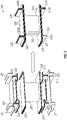
- FIG. 5 exploded and assembled views of the CMC turbine blade or vane 201 of FIG. 2 are illustrated in greater detail.
- the external parts 211 and 221 and the airfoil section 230 are formed from CVI as a CVI preform while the internal parts 212 and 222 are formed from MI.
- the internal parts 212 and 222 are then assembled with the external parts 211 and 221 and the airfoil section 230 of the CVI preform into the CMC turbine blade or vane 201.
- the assembly of the internal parts 212 and 222 with the external parts 211 and 221 and the airfoil section 230 can be accomplished by sliding adjacent parts together as shown in FIG. 5 .
Landscapes
- Engineering & Computer Science (AREA)
- Chemical & Material Sciences (AREA)
- Mechanical Engineering (AREA)
- General Engineering & Computer Science (AREA)
- Materials Engineering (AREA)
- Ceramic Engineering (AREA)
- Composite Materials (AREA)
- Turbine Rotor Nozzle Sealing (AREA)
Abstract
Description
- The present disclosure relates to the formation of certain gas turbine engine components and, more particularly, to a hybrid platform manufacturing method for gas turbine engine components.
- Creating ceramic matrix composite (CMC) hardware is typically a relatively long process. This process for a given CMC part can begin with preforming of the CMC part, which is followed by interface coating (IFC) processing. Next, the CMC part is subject to chemical vapor infiltration (CVI) processing to densify the CMC part. In addition, the CMC part creation process can include a leveraging of melt infiltration (MI) processing by creating MI processed platform flange inserts. It is often the goal to manage these and other stages in multiple phases as such management tends to create better CMC parts.
CMC parts that are formed by way of CVI tend to be porous, with voids and cavities that lead to less thermal conductivity. - Accordingly, an improved method of creating CMC parts is needed.
- According to an aspect of the disclosure, a method of assembling a ceramic matrix composite (CMC) component is provided. The method includes assessing which portions of the CMC component require relatively high-temperature capability and which portions require at least one of strength, thickness and increased thermal conductivity, making the portions that require the relatively high temperature capability with chemical vapor infiltration (CVI), making the portions that require the at least one of strength, thickness and increased thermal conductivity with melt infiltration (MI) and combining the portions that require the relatively high temperature capability with the CVI and the portions that require the at least one of strength, thickness and increased thermal conductivity with the MI.
- In accordance with additional or alternative embodiments, the CMC component includes a turbine blade or vane.
- In accordance with additional or alternative embodiments, the turbine blade or vane includes a platform and an airfoil section.
- In accordance with additional or alternative embodiments, the portions that require the relatively high temperature capability include the airfoil section.
- In accordance with additional or alternative embodiments, the portions that require the relatively high temperature capability include external parts of the platform and the portions that require the at least one of strength, thickness and increased thermal conductivity include internal parts of the platform.
- In accordance with additional or alternative embodiments, the external parts of the platform include gas path facing surfaces.
- In accordance with additional or alternative embodiments, the gas path facing surfaces have a minimum thickness of about 0.005 inches (0.0127 mm).
- In accordance with additional or alternative embodiments, the internal parts of the platform include radial flanges.
- In accordance with additional or alternative embodiments, the internal parts of the platform are T-shaped.
- In accordance with additional or alternative embodiments, the combining includes mechanically fitting together the portions that require the relatively high temperature capability and the portions that require the at least one of strength, thickness and increased thermal conductivity.
- In accordance with additional or alternative embodiments, the combining includes sliding the portions that require the at least one of strength, thickness and increased thermal conductivity into the portions that require the relatively high temperature capability.
- According to an aspect of the disclosure, which the Applicant expressly reserves the right to claim independently, a method of assembling a ceramic matrix composite (CMC) turbine blade or vane is provided. The method includes forming internal parts of a platform using melt infiltration (MI), forming external parts of the platform and an airfoil section using chemical vapor infiltration (CVI) and mechanically fitting the internal parts of the platform with the external parts of the platform.
- In accordance with additional or alternative embodiments, the external parts of the platform include gas path facing surfaces.
- In accordance with additional or alternative embodiments, the gas path facing surfaces have a minimum thickness of about 0.005 inches (0.0127 mm).
- In accordance with additional or alternative embodiments, the internal parts of the platform include radial flanges.
- In accordance with additional or alternative embodiments, the internal parts of the platform are T-shaped.
- In accordance with additional or alternative embodiments, the internal parts of the platform are slidable relative to the external parts of the platform.
- According to an aspect of the disclosure, a ceramic matrix composite (CMC) turbine blade or vane is provided. The CMC turbine blade or vane includes a platform including external parts and internal parts mechanically fit with the external parts and an airfoil section disposed with the platform. The external parts of the platform and the airfoil section are formed from chemical vapor infiltration (CVI) and the internal parts of the platform are formed from melt infiltration (MI).
- In accordance with additional or alternative embodiments, the external parts of the platform include gas path facing surfaces having a minimum thickness of about 0.005 inches (0.0127 mm).
- In accordance with additional or alternative embodiments, the internal parts of the platform are T-shaped and include radial flanges.
- Additional features and advantages are realized through the techniques of the present disclosure. Other embodiments and aspects of the disclosure are described in detail herein and are considered a part of the claimed technical concept. For a better understanding of the disclosure with the advantages and the features, refer to the description and to the drawings.
- For a more complete understanding of this disclosure, reference is now made to the following brief description, taken in connection with the accompanying drawings and detailed description, wherein like reference numerals represent like parts:
-
FIG. 1 is a partial cross-sectional view of a gas turbine engine in accordance with embodiments; -
FIG. 2 is a perspective view of a CMC turbine blade or vane in accordance with embodiments; -
FIG. 3 is a flow diagram illustrating a method of assembling a CMC turbine blade or vane in accordance with embodiments; -
FIG. 4 is a flow diagram illustrating a method of assembling a CMC turbine blade or vane in accordance with embodiments; and -
FIG. 5 illustrates exploded and assembled views of the CMC turbine blade in accordance with embodiments. - As noted above, CMC parts formed with CVI can exhibit limitations on cold side features where added thickness for strength is often needed. Particularly, CMC parts with flanges that carry vane aerodynamic loads are especially difficult to manufacture with CVI and achieve structural needs. Thus, as will be described below, a CMC component is manufactured in a piecemeal manner with CVI and MI portions where the CVI portions are built in different manners from the MI portions. For example, the airfoil portion of a vane and certain portions of platforms could be made via CVI but other portions of the platforms would be made with MI. This hybrid scheme will reap the benefits of each process for maximum CMC component capability.
- A detailed description of one or more embodiments of the disclosed apparatus and method are presented herein by way of exemplification and not limitation with reference to the Figures.
-
FIG. 1 schematically illustrates agas turbine engine 20. Thegas turbine engine 20 is disclosed herein as a two-spool turbofan that generally incorporates afan section 22, acompressor section 24, acombustor section 26 and aturbine section 28. Alternative engines might include other systems or features. Thefan section 22 drives air along a bypass flow path B in a bypass duct, while thecompressor section 24 drives air along a core flow path C for compression and communication into thecombustor section 26 then expansion through theturbine section 28. Although depicted as a two-spool turbofan gas turbine engine in the disclosed non-limiting embodiment, it should be understood that the concepts described herein are not limited to use with two-spool turbofans as the teachings may be applied to other types of turbine engines including three-spool architectures. - The
exemplary engine 20 generally includes alow speed spool 30 and ahigh speed spool 32 mounted for rotation about an engine central longitudinal axis A relative to an enginestatic structure 36 viaseveral bearing systems 38. It should be understood thatvarious bearing systems 38 at various locations may alternatively or additionally be provided, and the location ofbearing systems 38 may be varied as appropriate to the application. - The
low speed spool 30 generally includes aninner shaft 40 that interconnects afan 42, alow pressure compressor 44 and alow pressure turbine 46. Theinner shaft 40 is connected to thefan 42 through a speed change mechanism, which in exemplarygas turbine engine 20 is illustrated as a gearedarchitecture 48 to drive thefan 42 at a lower speed than thelow speed spool 30. Thehigh speed spool 32 includes anouter shaft 50 that interconnects ahigh pressure compressor 52 andhigh pressure turbine 54. Acombustor 56 is arranged inexemplary gas turbine 20 between thehigh pressure compressor 52 and thehigh pressure turbine 54. An enginestatic structure 36 is arranged generally between thehigh pressure turbine 54 and thelow pressure turbine 46. The enginestatic structure 36 further supports bearingsystems 38 in theturbine section 28. Theinner shaft 40 and theouter shaft 50 are concentric and rotate viabearing systems 38 about the engine central longitudinal axis A which is collinear with their longitudinal axes. - The core airflow is compressed by the
low pressure compressor 44 then thehigh pressure compressor 52, mixed and burned with fuel in thecombustor 56, then expanded over thehigh pressure turbine 54 andlow pressure turbine 46. Theturbines low speed spool 30 andhigh speed spool 32 in response to the expansion. It will be appreciated that each of the positions of thefan section 22,compressor section 24,combustor section 26,turbine section 28, and fandrive gear system 48 may be varied. For example,gear system 48 may be located aft ofcombustor section 26 or even aft ofturbine section 28, andfan section 22 may be positioned forward or aft of the location ofgear system 48. - The
engine 20 in one example is a high-bypass geared aircraft engine. In a further example, theengine 20 bypass ratio is greater than about six (6), with an example embodiment being greater than about ten (10), the gearedarchitecture 48 is an epicyclic gear train, such as a planetary gear system or other gear system, with a gear reduction ratio of greater than about 2.3 and thelow pressure turbine 46 has a pressure ratio that is greater than about five. In one disclosed embodiment, theengine 20 bypass ratio is greater than about ten (10:1), the fan diameter is significantly larger than that of thelow pressure compressor 44, and thelow pressure turbine 46 has a pressure ratio that is greater than about five 5:1.Low pressure turbine 46 pressure ratio is pressure measured prior to inlet oflow pressure turbine 46 as related to the pressure at the outlet of thelow pressure turbine 46 prior to an exhaust nozzle. The gearedarchitecture 48 may be an epicycle gear train, such as a planetary gear system or other gear system, with a gear reduction ratio of greater than about 2.3: 1. It should be understood, however, that the above parameters are only exemplary of one embodiment of a geared architecture engine and that the present disclosure is applicable to other gas turbine engines including direct drive turbofans. - A significant amount of thrust is provided by the bypass flow B due to the high bypass ratio. The
fan section 22 of theengine 20 is designed for a particular flight condition--typically cruise at about 0.8Mach and about 35,000 feet (10,688 meters). The flight condition of 0.8 Mach and 35,000 ft (10,688 meters), with the engine at its best fuel consumption--also known as "bucket cruise Thrust Specific Fuel Consumption ('TSFC')"--is the industry standard parameter of lbm of fuel being burned divided by lbf of thrust the engine produces at that minimum point. "Low fan pressure ratio" is the pressure ratio across the fan blade alone, without a Fan Exit Guide Vane ("FEGV") system. The low fan pressure ratio as disclosed herein according to one non-limiting embodiment is less than about 1.45. "Low corrected fan tip speed" is the actual fan tip speed in ft/sec divided by an industry standard temperature correction of [(Tram °R)/(518.7 °R)]0.5. The "Low corrected fan tip speed" as disclosed herein according to one non-limiting embodiment is less than about 1150 ft/second (350.5 m/sec). - With reference to
FIG. 2 , a ceramic matrix composite (CMC) turbine blade orvane 201 is provided. The CMC turbine blade or vane includes aninner platform 210, anouter platform 220 and anairfoil section 230 interposed between theinner platform 210 and theouter platform 220. Theinner platform 210 includesexternal parts 211 andinternal parts 212 that are mechanically fittable with or slidable relative to theexternal parts 211. Theouter platform 220 includesexternal parts 221 andinternal parts 222 that are mechanically fittable with or slidable relative to theexternal parts 221. Theairfoil section 230 includes leading and trailing edges and pressure and suction surfaces extending between the leading and trailing edges. In accordance with embodiments, theexternal parts path facing surfaces internal parts radial flanges - While the CMC turbine blade or
vane 201 has been described as having theinner platform 210 and theouter platform 220, it is to be understood that this is not required and that other embodiments exist. As an example, the CMC turbine blade orvane 201 may not have anouter platform 220 in which case theairfoil section 230 can be disposed with theinner platform 210. For purposes of clarity and brevity, however, the following description will relate to the case in which the CMC turbine blade orvane 201 has both theinner platform 210 and theouter platform 220 with theairfoil section 230 interposed between theinner platform 210 and theouter platform 220. - With the construction described above, the
external parts airfoil section 230 can be exposed to high temperature and high pressure fluids (i.e., during an operation of a gas turbine engine in which the CMC turbine blade orvane 201 is installed). As such, theexternal parts airfoil section 230 are designed for high temperature capabilities and are therefore formed from CVI processing. By contrast, theinternal parts vane 201. Therefore, theinternal parts - With reference to
FIG. 3 , a method of assembling a CMC component is provided. As shown inFIG. 3 , the method includes assessing which portions of the CMC component require relatively high-temperature capability and which portions require at least one of strength, thickness and increasedthermal conductivity 301, making the portions that require the relatively high temperature capability with chemical vapor infiltration (CVI) 302, making the portions that require the at least one of strength, thickness and increased thermal conductivity with melt infiltration (MI) 303 and combining the portions that require the relatively high temperature capability with the CVI and the portions that require the at least one of strength, thickness and increased thermal conductivity with theMI 304. The combining ofoperation 304 includes at least one of mechanically fitting together the portions that require the relatively high temperature capability and the portions that require the at least one of strength, thickness and increased thermal conductivity and sliding the portions that require the at least one of strength, thickness and increased thermal conductivity into the portions that require the relatively high temperature capability. - In accordance with embodiments, the CMC component includes a turbine blade or vane that includes an inner platform, an outer platform and an airfoil section interposed between the inner and outer platforms. The portions that require the relatively high temperature capability include the airfoil section and external parts of the inner and outer platforms and the portions that require the at least one of strength, thickness and increased thermal conductivity include internal parts of the inner and outer platforms. The external parts of the inner and outer platforms include gas path facing surfaces and can have a minimum thickness of about 0.005 inches (0.0127 mm). The internal parts of the inner and outer platforms include radial flanges and are T-shaped.
- With reference to
FIG. 4 , a method of assembling a CMC turbine blade or vane is provided. As shown inFIG. 4 , the method includes forming internal parts of inner and outer platforms using melt infiltration (MI) 401, forming external parts of the inner and outer platforms and an airfoil section using chemical vapor infiltration (CVI) 402, mechanically fitting or sliding the internal parts of the inner and outer platforms with the external parts of the inner and outer platforms 403 and interposing the airfoil section between the inner andouter platforms 404. Regarding the interposing of the airfoil section between the inner and outer platforms ofoperation 404, it is to be understood that the airfoil section can be formed monolithically or integrally with portions of the inner and outer platforms in some embodiments. In these or other cases, the airfoil section is effectively interposed between the inner and outer platforms. - In accordance with embodiments, the external parts of the inner and outer platforms include gas path facing surfaces having a minimum thickness of about 0.005 inches (0.0127 mm) and the internal parts of the inner and outer platforms include radial flanges and are T-shaped and are slidable relative to the external parts of the inner and outer platforms.
- In accordance with embodiments, at least the internal parts of the inner and outer platforms can have thermal conductivity properties of about 60 BTU-in/h-ft2-F (8.4 W /mK).
- With reference back to
FIG. 2 and with additional reference toFIG. 5 , exploded and assembled views of the CMC turbine blade orvane 201 ofFIG. 2 are illustrated in greater detail. As shown inFIG. 5 , theexternal parts airfoil section 230 are formed from CVI as a CVI preform while theinternal parts internal parts external parts airfoil section 230 of the CVI preform into the CMC turbine blade orvane 201. The assembly of theinternal parts external parts airfoil section 230 can be accomplished by sliding adjacent parts together as shown inFIG. 5 . - Technical effects and benefits of the present disclosure are the provision of methods of manufacturing designed to create improved durability in CMC components. This is accomplished by leveraging manufacturing techniques that are most ideal for certain features of CMC components.
- The corresponding structures, materials, acts, and equivalents of all means or step plus function elements in the claims below are intended to include any structure, material, or act for performing the function in combination with other claimed elements as specifically claimed. The description of the present disclosure has been presented for purposes of illustration and description, but is not intended to be exhaustive or limited to the technical concepts in the form disclosed. Many modifications and variations will be apparent to those of ordinary skill in the art without departing from the scope and spirit of the disclosure. The embodiments were chosen and described in order to best explain the principles of the disclosure and the practical application, and to enable others of ordinary skill in the art to understand the disclosure for various embodiments with various modifications as are suited to the particular use contemplated.
- While the preferred embodiments to the disclosure have been described, it will be understood that those skilled in the art, both now and in the future, may make various improvements and enhancements which fall within the scope of the claims which follow. These claims should be construed to maintain the proper protection for the disclosure first described.
Claims (14)
- A method of assembling a ceramic matrix composite (CMC) component (201), the method comprising:assessing which portions of the CMC component (201) require relatively high-temperature capability and which portions require at least one of strength, thickness and increased thermal conductivity;making the portions that require the relatively high temperature capability with chemical vapor infiltration (CVI);making the portions that require the at least one of strength, thickness and increased thermal conductivity with melt infiltration (MI); andcombining the portions that require the relatively high temperature capability with the CVI and the portions that require the at least one of strength, thickness and increased thermal conductivity with the MI.
- The method according to claim 1, wherein the CMC component (201) comprises a turbine blade or vane (201).
- The method according to claim 2, wherein the turbine blade or vane (201) comprises a platform (210; 220) and an airfoil section (230).
- The method according to claim 3, wherein the portions that require the relatively high temperature capability comprise the airfoil section (230).
- The method according to claim 3 or 4, wherein:the portions that require the relatively high temperature capability comprise external parts (211; 221) of the platform (210; 220), andthe portions that require the at least one of strength, thickness and increased thermal conductivity comprise internal parts (212; 222) of the platform (210; 220).
- The method according to claim 5, wherein the external parts (211; 221) of the platform (210; 220) comprise gas path facing surfaces (2110; 2210).
- The method according to claim 6, wherein the gas path facing surfaces (2110; 2210) have a minimum thickness of about 0.005 inches (0.0127 mm).
- The method according to any of claims 5 to 7, wherein the internal parts (212; 222) of the platform (210; 220) comprise radial flanges (2120; 2220).
- The method according to any of claims 5 to 8, wherein the internal parts (212; 222) of the platform (210; 220) are T-shaped.
- The method according to any preceding claim, wherein the combining comprises mechanically fitting together the portions that require the relatively high temperature capability and the portions that require the at least one of strength, thickness and increased thermal conductivity.
- The method according to any preceding claim, wherein the combining comprises sliding the portions that require the at least one of strength, thickness and increased thermal conductivity into the portions that require the relatively high temperature capability.
- A ceramic matrix composite (CMC) turbine blade or vane (201), comprising:a platform (210; 220) comprising external parts (211; 221) and internal parts (212; 222) mechanically fit with the external parts (211; 221); andan airfoil section (230) disposed with the platform (210; 220), the external parts (211; 221) of the platform (210; 220) and the airfoil section (230) being formed from chemical vapor infiltration (CVI) and the internal parts (212; 222) of the platform (210; 220) being formed from melt infiltration (MI).
- The CMC turbine blade or vane (201) according to claim 12, wherein the external parts (211; 221) of the platform (210; 220) comprise gas path facing surfaces (2110; 2210) having a minimum thickness of about 0.005 inches (0.0127 mm).
- The CMC turbine blade or vane (201) according to claim 12 or 13, wherein the internal parts (212; 222) of the platform (210; 220) are T-shaped and comprise radial flanges (2120; 2220).
Applications Claiming Priority (1)
| Application Number | Priority Date | Filing Date | Title |
|---|---|---|---|
| US17/339,567 US12173621B2 (en) | 2021-06-04 | 2021-06-04 | Hybrid platform manufacturing |
Publications (1)
| Publication Number | Publication Date |
|---|---|
| EP4098844A1 true EP4098844A1 (en) | 2022-12-07 |
Family
ID=81851300
Family Applications (1)
| Application Number | Title | Priority Date | Filing Date |
|---|---|---|---|
| EP22175957.4A Pending EP4098844A1 (en) | 2021-06-04 | 2022-05-27 | Hybrid platform manufacturing |
Country Status (2)
| Country | Link |
|---|---|
| US (1) | US12173621B2 (en) |
| EP (1) | EP4098844A1 (en) |
Families Citing this family (1)
| Publication number | Priority date | Publication date | Assignee | Title |
|---|---|---|---|---|
| US12428965B2 (en) * | 2024-01-31 | 2025-09-30 | Rtx Corporation | Load bearing feature for ceramic matrix composite turbine components |
Citations (1)
| Publication number | Priority date | Publication date | Assignee | Title |
|---|---|---|---|---|
| US20190084892A1 (en) * | 2017-09-21 | 2019-03-21 | General Electric Company | Ceramic matrix composite articles |
Family Cites Families (8)
| Publication number | Priority date | Publication date | Assignee | Title |
|---|---|---|---|---|
| US7427428B1 (en) * | 2003-06-24 | 2008-09-23 | The United States Of America As Represented By The Administrator Of The National Aeronautics And Space Administration | Interphase for ceramic matrix composites reinforced by non-oxide ceramic fibers |
| DE102007027465A1 (en) * | 2007-06-14 | 2008-12-18 | Rolls-Royce Deutschland Ltd & Co Kg | Gas turbine blade with modular construction |
| US8231354B2 (en) * | 2009-12-15 | 2012-07-31 | Siemens Energy, Inc. | Turbine engine airfoil and platform assembly |
| US20130167374A1 (en) * | 2011-12-29 | 2013-07-04 | General Electric Company | Process of producing ceramic matrix composites and ceramic matrix composites formed thereby |
| US11028696B2 (en) * | 2017-08-07 | 2021-06-08 | General Electric Company | Ceramic matrix composite airfoil repair |
| US10737986B2 (en) * | 2017-09-19 | 2020-08-11 | General Electric Company | Methods for repairing composite cylinders |
| US10329201B2 (en) * | 2017-09-21 | 2019-06-25 | General Electric Company | Ceramic matrix composite articles formation method |
| US10934870B2 (en) * | 2018-09-17 | 2021-03-02 | Rolls Royce Plc | Turbine vane assembly with reinforced end wall joints |
-
2021
- 2021-06-04 US US17/339,567 patent/US12173621B2/en active Active
-
2022
- 2022-05-27 EP EP22175957.4A patent/EP4098844A1/en active Pending
Patent Citations (1)
| Publication number | Priority date | Publication date | Assignee | Title |
|---|---|---|---|---|
| US20190084892A1 (en) * | 2017-09-21 | 2019-03-21 | General Electric Company | Ceramic matrix composite articles |
Also Published As
| Publication number | Publication date |
|---|---|
| US20220389823A1 (en) | 2022-12-08 |
| US12173621B2 (en) | 2024-12-24 |
Similar Documents
| Publication | Publication Date | Title |
|---|---|---|
| EP3819477B1 (en) | Feather seal slot arrangement for a cmc blade outer air seal assembly | |
| US11125096B2 (en) | CMC boas arrangement | |
| US11319827B2 (en) | Intersegment seal for blade outer air seal | |
| US20210285334A1 (en) | Compact pin attachment for cmc components | |
| US20200063592A1 (en) | Blade outer air seal formed of laminate and having radial support hooks | |
| US20210254504A1 (en) | Method of creating heat transfer features in high temperature alloys | |
| EP2956646B1 (en) | Component for a gas turbine engine and corresponding method of forming a cooling hole | |
| US10190420B2 (en) | Flared crossovers for airfoils | |
| US20260043335A1 (en) | Seal arc segment with cmc ply cutouts for cooling channels | |
| US11098612B2 (en) | Blade outer air seal including cooling trench | |
| EP4098844A1 (en) | Hybrid platform manufacturing | |
| US20210156271A1 (en) | Vane with collar | |
| EP4545755A1 (en) | Airfoil and gas turbine engine | |
| EP4461925A1 (en) | Method for cmc airfoil using core tube of rigidized ceramic fabric | |
| EP4379192A1 (en) | Seal slot with coating | |
| EP4379191A1 (en) | Seal slot with coating and method of coating a seal slot | |
| US11725519B2 (en) | Platform for an airfoil of a gas turbine engine | |
| US11220917B1 (en) | Diffused cooling arrangement for gas turbine engine components | |
| US11098608B2 (en) | CMC BOAS with internal support structure | |
| US20210003026A1 (en) | Double box boas and carrier system | |
| US11802487B1 (en) | Gas turbine engine stator vane formed of ceramic matrix composites and having attachment flanges | |
| EP3392567A1 (en) | Combustor liner panel end rail | |
| EP4442671A1 (en) | Method for manufacturing multiple seal arc segments | |
| EP4317109A1 (en) | Ceramic matrix composite article and method of making the same | |
| US11732589B1 (en) | Airfoil vane multiplet with interleaved fiber plies |
Legal Events
| Date | Code | Title | Description |
|---|---|---|---|
| PUAI | Public reference made under article 153(3) epc to a published international application that has entered the european phase |
Free format text: ORIGINAL CODE: 0009012 |
|
| STAA | Information on the status of an ep patent application or granted ep patent |
Free format text: STATUS: THE APPLICATION HAS BEEN PUBLISHED |
|
| AK | Designated contracting states |
Kind code of ref document: A1 Designated state(s): AL AT BE BG CH CY CZ DE DK EE ES FI FR GB GR HR HU IE IS IT LI LT LU LV MC MK MT NL NO PL PT RO RS SE SI SK SM TR |
|
| STAA | Information on the status of an ep patent application or granted ep patent |
Free format text: STATUS: REQUEST FOR EXAMINATION WAS MADE |
|
| 17P | Request for examination filed |
Effective date: 20230607 |
|
| RBV | Designated contracting states (corrected) |
Designated state(s): AL AT BE BG CH CY CZ DE DK EE ES FI FR GB GR HR HU IE IS IT LI LT LU LV MC MK MT NL NO PL PT RO RS SE SI SK SM TR |
|
| RAP3 | Party data changed (applicant data changed or rights of an application transferred) |
Owner name: RTX CORPORATION |
|
| STAA | Information on the status of an ep patent application or granted ep patent |
Free format text: STATUS: EXAMINATION IS IN PROGRESS |
|
| 17Q | First examination report despatched |
Effective date: 20240521 |