EP4098810A1 - Construction machine - Google Patents
Construction machine Download PDFInfo
- Publication number
- EP4098810A1 EP4098810A1 EP21828011.3A EP21828011A EP4098810A1 EP 4098810 A1 EP4098810 A1 EP 4098810A1 EP 21828011 A EP21828011 A EP 21828011A EP 4098810 A1 EP4098810 A1 EP 4098810A1
- Authority
- EP
- European Patent Office
- Prior art keywords
- control valve
- pressure
- actuator
- revolution speed
- controller
- Prior art date
- Legal status (The legal status is an assumption and is not a legal conclusion. Google has not performed a legal analysis and makes no representation as to the accuracy of the status listed.)
- Granted
Links
Images


Classifications
-
- E—FIXED CONSTRUCTIONS
- E02—HYDRAULIC ENGINEERING; FOUNDATIONS; SOIL SHIFTING
- E02F—DREDGING; SOIL-SHIFTING
- E02F9/00—Component parts of dredgers or soil-shifting machines, not restricted to one of the kinds covered by groups E02F3/00 - E02F7/00
- E02F9/20—Drives; Control devices
- E02F9/22—Hydraulic or pneumatic drives
- E02F9/2217—Hydraulic or pneumatic drives with energy recovery arrangements, e.g. using accumulators, flywheels
-
- E—FIXED CONSTRUCTIONS
- E02—HYDRAULIC ENGINEERING; FOUNDATIONS; SOIL SHIFTING
- E02F—DREDGING; SOIL-SHIFTING
- E02F9/00—Component parts of dredgers or soil-shifting machines, not restricted to one of the kinds covered by groups E02F3/00 - E02F7/00
- E02F9/20—Drives; Control devices
- E02F9/22—Hydraulic or pneumatic drives
- E02F9/2203—Arrangements for controlling the attitude of actuators, e.g. speed, floating function
-
- E—FIXED CONSTRUCTIONS
- E02—HYDRAULIC ENGINEERING; FOUNDATIONS; SOIL SHIFTING
- E02F—DREDGING; SOIL-SHIFTING
- E02F9/00—Component parts of dredgers or soil-shifting machines, not restricted to one of the kinds covered by groups E02F3/00 - E02F7/00
- E02F9/20—Drives; Control devices
- E02F9/22—Hydraulic or pneumatic drives
- E02F9/2221—Control of flow rate; Load sensing arrangements
-
- E—FIXED CONSTRUCTIONS
- E02—HYDRAULIC ENGINEERING; FOUNDATIONS; SOIL SHIFTING
- E02F—DREDGING; SOIL-SHIFTING
- E02F9/00—Component parts of dredgers or soil-shifting machines, not restricted to one of the kinds covered by groups E02F3/00 - E02F7/00
- E02F9/20—Drives; Control devices
- E02F9/22—Hydraulic or pneumatic drives
- E02F9/2278—Hydraulic circuits
- E02F9/2296—Systems with a variable displacement pump
-
- F—MECHANICAL ENGINEERING; LIGHTING; HEATING; WEAPONS; BLASTING
- F15—FLUID-PRESSURE ACTUATORS; HYDRAULICS OR PNEUMATICS IN GENERAL
- F15B—SYSTEMS ACTING BY MEANS OF FLUIDS IN GENERAL; FLUID-PRESSURE ACTUATORS, e.g. SERVOMOTORS; DETAILS OF FLUID-PRESSURE SYSTEMS, NOT OTHERWISE PROVIDED FOR
- F15B1/00—Installations or systems with accumulators; Supply reservoir or sump assemblies
- F15B1/02—Installations or systems with accumulators
- F15B1/024—Installations or systems with accumulators used as a supplementary power source, e.g. to store energy in idle periods to balance pump load
-
- F—MECHANICAL ENGINEERING; LIGHTING; HEATING; WEAPONS; BLASTING
- F15—FLUID-PRESSURE ACTUATORS; HYDRAULICS OR PNEUMATICS IN GENERAL
- F15B—SYSTEMS ACTING BY MEANS OF FLUIDS IN GENERAL; FLUID-PRESSURE ACTUATORS, e.g. SERVOMOTORS; DETAILS OF FLUID-PRESSURE SYSTEMS, NOT OTHERWISE PROVIDED FOR
- F15B21/00—Common features of fluid actuator systems; Fluid-pressure actuator systems or details thereof, not covered by any other group of this subclass
- F15B21/14—Energy-recuperation means
-
- B—PERFORMING OPERATIONS; TRANSPORTING
- B60—VEHICLES IN GENERAL
- B60Y—INDEXING SCHEME RELATING TO ASPECTS CROSS-CUTTING VEHICLE TECHNOLOGY
- B60Y2200/00—Type of vehicle
- B60Y2200/40—Special vehicles
- B60Y2200/41—Construction vehicles, e.g. graders, excavators
- B60Y2200/412—Excavators
-
- E—FIXED CONSTRUCTIONS
- E02—HYDRAULIC ENGINEERING; FOUNDATIONS; SOIL SHIFTING
- E02F—DREDGING; SOIL-SHIFTING
- E02F3/00—Dredgers; Soil-shifting machines
- E02F3/04—Dredgers; Soil-shifting machines mechanically-driven
- E02F3/28—Dredgers; Soil-shifting machines mechanically-driven with digging tools mounted on a dipper- or bucket-arm, i.e. there is either one arm or a pair of arms, e.g. dippers, buckets
- E02F3/36—Component parts
- E02F3/42—Drives for dippers, buckets, dipper-arms or bucket-arms
- E02F3/43—Control of dipper or bucket position; Control of sequence of drive operations
- E02F3/435—Control of dipper or bucket position; Control of sequence of drive operations for dipper-arms, backhoes or the like
-
- F—MECHANICAL ENGINEERING; LIGHTING; HEATING; WEAPONS; BLASTING
- F15—FLUID-PRESSURE ACTUATORS; HYDRAULICS OR PNEUMATICS IN GENERAL
- F15B—SYSTEMS ACTING BY MEANS OF FLUIDS IN GENERAL; FLUID-PRESSURE ACTUATORS, e.g. SERVOMOTORS; DETAILS OF FLUID-PRESSURE SYSTEMS, NOT OTHERWISE PROVIDED FOR
- F15B2211/00—Circuits for servomotor systems
- F15B2211/20—Fluid pressure source, e.g. accumulator or variable axial piston pump
- F15B2211/265—Control of multiple pressure sources
- F15B2211/2658—Control of multiple pressure sources by control of the prime movers
Definitions
- the present invention relates to a construction machine such as a hydraulic excavator.
- Patent Document 1 describes a fluid pressure actuator control circuit that can reduce fuel consumption by supplying a hydraulic fluid accumulated in an accumulator (pressure accumulating device) to a boom cylinder and correspondingly reducing a flow rate to be fed from a pump to the boom cylinder.
- an accumulator pressure accumulating device
- Patent Document 1 JP-2009-275771-A
- the present invention has been made in view of the above-described problems. It is an object of the present invention to provide a construction machine that is equipped with a pressure accumulating device, which accumulates the return oil of an actuator, and that is capable of adjusting the operation speed of the actuator according to the revolution speed of a prime mover.
- a construction machine including a prime mover, a hydraulic pump driven by the prime mover, a revolution speed setting device that sets a revolution speed of the prime mover, an actuator, a pressure accumulating device that accumulates a return oil of the actuator, a first control valve disposed on a hydraulic fluid line that connects the pressure accumulating device and the actuator to each other, an operation device that gives an instruction for operation of the actuator, and a controller that is inputted with an operation signal of the operation device and outputs a control signal to the first control valve, the controller being configured to control the first control valve according to an operation amount of the operation device and the revolution speed set by the revolution speed setting device.
- the flow rate of hydraulic fluid supplied and discharged to and from the actuator by the pressure accumulating device changes according to the revolution speed of the prime mover. It is thus possible to adjust the operation speed of the actuator according to the revolution speed of the prime mover.
- the operation speed of the actuator can be adjusted according to the revolution speed of the prime mover.
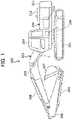
- FIG. 1 is a side view of a hydraulic excavator according to the present embodiment.
- a hydraulic excavator 200 includes a track structure 201, a swing structure 202 that is swingably disposed on the track structure 201 and constitutes a machine body, and a work device 203 that is vertically rotatably attached to the swing structure 202 and performs soil excavation work and the like.
- the swing structure 202 is driven by a swing motor 204.
- the work device 203 includes a boom 205 vertically rotatably attached to the swing structure 202, an arm 206 vertically rotatably attached to a distal end of the boom 205, and a bucket 207 vertically rotatably attached to a distal end of the arm 206.
- the boom 205 is driven by a boom cylinder 1.
- the arm 206 is driven by an arm cylinder 208.
- the bucket 207 is driven by a bucket cylinder 209.
- a cab 210 is provided in a front side position on the swing structure 202.
- a counterweight 211 that ensures a weight balance is provided in a rear side position on the swing structure 202.
- a machine room 212 is provided between the cab 210 and the counterweight 211.
- the machine room 212 houses an engine as a prime mover, a hydraulic pump, a control valve 213, and the like.
- the control valve 213 controls a flow of hydraulic fluid supplied to each actuator from the hydraulic pump.
- the prime mover in the present invention is not limited to an engine, and may be a motor whose revolution speed can be adjusted via an inverter.
- FIG. 2 is a circuit diagram of a hydraulic drive system included in the hydraulic excavator 200.
- a boom control lever 5 is an operation device for an operator to give an instruction for operation of the boom 205.
- the boom control lever 5 When the boom control lever 5 is operated in a boom raising direction, the boom control lever 5 outputs a boom raising pilot pressure Pu.
- the boom control lever 5 When the boom control lever 5 is operated in a boom lowering direction, the boom control lever 5 outputs a boom lowering pilot pressure Pd.
- the boom lowering pilot pressure Pd acts on a pilot check valve 10 and a pressure increasing control valve 9 to be described later.
- the boom lowering pilot pressure Pd is detected by a pressure sensor 11.
- the boom raising pilot pressure Pu is detected by a pressure sensor 12. Signals of the pressure sensors 11 and 12 are inputted to a controller 8.
- a work mode selector switch 6 is an operation device for the operator to select a work mode.
- a signal of the work mode selector switch 6 is inputted to the controller 8.
- An engine speed dial 7 is an operation device for the operator to set the revolution speed of an engine 20.
- a signal of the engine speed dial 7 is inputted to the controller 8. The operator can adjust the operation speed of the hydraulic excavator 200 by changing the engine speed via the engine speed dial 7.
- An accumulator 4 is a hydraulic apparatus that accumulates a return oil from a bottom side at a time of contraction of the boom cylinder 1, and supplies a hydraulic fluid to the bottom side at a time of extension of the boom cylinder 1.
- the accumulator 4 and a bottom side oil chamber 1a are connected to each other via a bottom side hydraulic fluid line 30.
- a control valve 2 (hereinafter a bottom side control valve) is disposed on the bottom side hydraulic fluid line 30.
- the bottom side control valve 2 changes an opening amount thereof according to a control signal from the controller 8, and thereby controls a flow rate to be supplied from the accumulator 4 to the bottom side oil chamber 1a of the boom cylinder 1 or a flow rate to be regenerated from the bottom side oil chamber 1a to the accumulator 4 (regeneration flow rate).
- the pilot check valve 10 is disposed on a hydraulic fluid line section of the bottom side hydraulic fluid line 30, the hydraulic fluid line section connecting the bottom side control valve 2 and the bottom side oil chamber 1a to each other.
- the pilot check valve 10 inhibits the hydraulic fluid from flowing out of the bottom side oil chamber 1a when the boom lowering pilot pressure Pd does not act on the pilot check valve 10.
- the pilot check valve 10 allows the hydraulic fluid to flow out of the bottom side oil chamber 1a when the boom lowering pilot pressure Pd acts on the pilot check valve 10.
- a bottom pressure is maintained unless the boom control lever 5 is operated in the boom lowering direction. It is thus possible to prevent the boom 205 from falling against an intention of the operator.
- a rod side oil chamber 1b of the boom cylinder 1 is connected to a hydraulic operating fluid tank 14 via a rod side hydraulic fluid line 31.
- a control valve 3 (hereinafter a rod side control valve) is disposed on the rod side hydraulic fluid line 31.
- the rod side control valve 3 adjusts an opening amount thereof according to a control signal from the controller 8, and thereby controls a flow rate to be discharged from the rod side oil chamber 1b of the boom cylinder 1 to the hydraulic operating fluid tank 14.
- the pressure increasing control valve 9 is disposed on the communication hydraulic fluid line 32.
- the pressure increasing control valve 9 is closed when the boom lowering pilot pressure Pd does not act on the pressure increasing control valve 9.
- the pressure increasing control valve 9 is opened when the boom lowering pilot pressure Pd acts on the pressure increasing control valve 9.
- the bottom pressure can be increased by the bottom side hydraulic fluid line 30 being made to communicate with the rod side hydraulic fluid line 31 via the pressure increasing control valve 9 at a time of a boom lowering operation.
- the controller 8 opens the bottom side control valve 2.
- the pressure maintaining function of the pilot check valve 10 is cancelled by the boom lowering pilot pressure Pd, and the pressure increasing control valve 9 is opened to increase the pressure on the bottom side of the boom cylinder 1. Consequently, the hydraulic fluid of the bottom side oil chamber 1a of the boom cylinder 1 is supplied to the accumulator 4 and the rod side oil chamber 1b, and the boom cylinder 1 performs a contracting operation.
- the controller 8 opens the bottom side control valve 2 and the rod side control valve 3. At this time, the pressure increasing control valve 9 is closed, and hence, the bottom side of the boom cylinder 1 is not increased in pressure. Consequently, the hydraulic fluid of the accumulator 4 is supplied to the bottom side oil chamber 1a of the boom cylinder 1, the hydraulic operating fluid of the rod side oil chamber 1b is discharged into the hydraulic operating fluid tank 14 via the rod side control valve 3, and the boom cylinder 1 performs an extending operation.
- a hydraulic pump 13 is a hydraulic apparatus for supplying the hydraulic fluid to the accumulator 4 and other unillustrated actuators.
- the hydraulic pump 13 is driven by the engine 20.
- a delivery port of the hydraulic pump 13 is connected to either the hydraulic operating fluid tank 14 or the accumulator 4 via a charge control valve 18.
- the charge control valve 18 is switched according to a control signal from the controller 8.
- the pressure of the accumulator 4 is detected by a pressure sensor 19.
- a signal of the pressure sensor 19 is inputted to the controller 8.
- the controller 8 can maintain the pressure of the accumulator 4 by switching the charge control valve 18 according to the pressure of the accumulator 4.
- FIG. 3 is a diagram illustrating processing contents of the controller 8.
- a pressure sensor signal 112 is a signal inputted to the controller 8 according to the boom raising pilot pressure Pu (boom raising operation amount) detected by the pressure sensor 12.
- a pressure sensor signal 111 is a signal inputted to the controller 8 according to the boom lowering pilot pressure Pd (boom lowering operation amount) detected by the pressure sensor 11.
- An engine speed dial signal 107 is a signal inputted to the controller 8 according to the engine speed set by the engine speed dial 7.
- a work mode selector switch signal 106 is a signal inputted to the controller 8 according to the work mode selected by the work mode selector switch 6.
- a pressure sensor signal 119 is a signal inputted to the controller 8 according to the pressure of the accumulator 4 detected by the pressure sensor 19.
- a function generating section 120 converts the pressure sensor signal 112 (boom raising operation amount) into a target opening amount of the rod side control valve 3, and outputs the target opening amount to an output converting section 121.
- the output converting section 121 outputs, to the rod side control valve 3, a control signal corresponding to the target opening amount from the function generating section 120.
- the rod side control valve 3 is opened according to the boom raising operation amount, and the hydraulic operating fluid on the rod side of the boom cylinder 1 is discharged into the hydraulic operating fluid tank 14.
- a function generating section 122 converts the pressure sensor signal 112 (boom raising operation amount) into a target opening amount of the bottom side control valve 2, and outputs the target opening amount to a multiplying section 123.
- a function generating section 124 converts the pressure sensor signal 111 (boom lowering operation amount) into a target opening amount of the bottom side control valve 2, and outputs the target opening amount to a multiplying section 125.
- a function generating section 126 outputs a gain corresponding to the engine speed dial signal 107 (engine speed) and the work mode selector switch signal 106 (work mode) to the multiplying sections 123 and 125.
- FIG. 4 is a diagram illustrating a correspondence relation between the engine speed and the work mode and the gain.
- Three characteristics a, b, and c are set in the function generating section 110 in the present embodiment.
- the function generating section 110 selects one of the characteristics a, b, and c according to the work mode. For example, the characteristic a is selected in a work mode in which importance is attached to work efficiency.
- the characteristics b and c are selected in work modes in which importance is attached to energy saving.
- the gain of the characteristic a continuously increases from a lower limit value (for example, 0.3) to an upper limit value (1.0) according to the engine speed.
- the gain of the characteristic b continuously increases from a minimum value (0.3) to a predetermined upper limit value (for example, 0.9) according to the engine speed.
- the gain of the characteristic c continuously increases from a lower limit value (0.3) to a predetermined upper limit value (for example, 0.8) according to the engine speed.
- the multiplying section 123 multiplies the target opening amount from the function generating section 122 by the gain from the function generating section 126, and outputs the target opening amount multiplied by the gain to a maximum value selecting section 127.
- the multiplying section 125 multiplies the target opening amount from the function generating section 124 by the gain from the function generating section 126, and outputs the target opening amount multiplied by the gain to the maximum value selecting section 127.
- the maximum value selecting section 127 selects the larger of the target opening amount from the multiplying section 123 and the target opening amount from the multiplying section 125, and outputs the larger target opening amount to an output converting section 128.
- the output converting section 128 outputs, to the bottom side control valve 2, a control valve control signal 102 corresponding to the target opening amount from the maximum value selecting section 127.
- the bottom side control valve 2 is opened according to the boom raising operation amount, and the hydraulic fluid of the accumulator 4 is supplied to the bottom side of the boom cylinder 1.
- the bottom side control valve 2 is opened according to the boom lowering operation amount, a part of the hydraulic fluid on the bottom side of the boom cylinder 1 that is increased in pressure by the pressure increasing control valve 9 being opened is accumulated in the accumulator 4, and a remaining part is supplied to the rod side of the boom cylinder 1.
- a function generating section 129 converts the pressure sensor signal 119 (pressure of the accumulator 4) into an ON/OFF position of the charge control valve 18, and outputs the ON/OFF position to an output converting section 130. Specifically, when the pressure of the accumulator 4 is lower than a predetermined value, an ON position is output. When the pressure of the accumulator 4 is equal to or higher than the predetermined value, an OFF position is output.
- the output converting section 130 outputs, to the charge control valve 18, a control valve control signal corresponding to the ON/OFF position from the function generating section 129. Hence, when the pressure of the accumulator 4 falls below the predetermined value, pressure is accumulated in the accumulator 4 by the hydraulic pump 13.
- a construction machine 200 including an engine 20, a revolution speed setting device 7 for setting a revolution speed of the engine 20, an actuator 1, a pressure accumulating device 4 that accumulates a return oil from the actuator 1, a first control valve 2 disposed on a hydraulic fluid line 30 that connects the pressure accumulating device 4 and the actuator 1 to each other, an operation device 5 for giving an instruction for operation of the actuator 1, and a controller 8 that is inputted with an operation signal of the operation device 5 and outputs a control signal to the first control valve 2, the controller 8 controls the first control valve 2 according to the operation amount of the operation device 5 and the revolution speed set by the revolution speed setting device 7.
- the flow rate of the hydraulic fluid supplied and discharged to and from the actuator 1 by the pressure accumulating device 4 changes according to the revolution speed of the prime mover 20. It is thereby possible to adjust the operation speed of the actuator 1 according to the revolution speed of the prime mover 20, and maintain a speed balance between the actuator 1 supplied with the hydraulic fluid from the pressure accumulating device 4 and other actuators supplied with the hydraulic fluid from the hydraulic pump 13 when work is performed while the revolution speed of the prime mover 20 is decreased.
- the construction machine 200 includes a hydraulic operating fluid tank 14, a hydraulic pump 13 that is driven by the prime mover 20 and sucks a hydraulic operating fluid from the hydraulic operating fluid tank 14 and delivers the hydraulic operating fluid, a pressure sensor 19 that detects a pressure of the pressure accumulating device 4, and a second control valve 18 that connects a delivery port of the hydraulic pump 13 to one of the hydraulic operating fluid tank 14 and the pressure accumulating device 4 according to a control signal from the controller 8.
- the controller 8 outputs the control signal to the second control valve 18 such that the delivery port of the hydraulic pump 13 is connected to the hydraulic operating fluid tank 14 when the pressure detected by the pressure sensor 19 is equal to or higher than a predetermined pressure and such that the delivery port of the hydraulic pump 13 is connected to the pressure accumulating device 4 when the pressure detected by the pressure sensor 19 is lower than the predetermined pressure.
- the pressure of the pressure accumulating device 4 is kept equal to or higher than the predetermined pressure, so that the actuator 1 can be driven in any timing.
- the construction machine 200 includes a boom 205, and the actuator 1 is a boom cylinder that drives the boom 205.
- the operator can adjust the operation speed of the boom cylinder 1 by changing the revolution speed of the prime mover 20 via the revolution speed setting device 7.
- the prime mover 20 is an engine
- the revolution speed setting device 7 is an engine speed dial that sets a revolution speed of the engine 20
- the target opening amount is computed by multiplying an opening amount of the first control valve 2, the opening amount corresponding to the operation amount of the operation device 5, by a gain corresponding to the revolution speed set by the engine speed dial 7. It is thereby possible to adjust the operation speed of the actuator 1 via an operation of the engine speed dial 7.
- the construction machine 200 includes a work mode selecting device 6 for selecting a work mode, and the controller 8 changes an upper limit value of the gain according to the work mode selected by the work mode selecting device 6. The operator can thereby limit a maximum operation speed of the actuator 1 according to the work mode selected via the work mode selecting device 6.
- the bottom side control valve 2 and the rod side control valve 3 are configured to be controlled by control signals corresponding to target opening amounts in the present embodiment
- a flow control valve controlled by a control signal corresponding to a target flow rate can be used as the bottom side control valve 2 and the rod side control valve 3.
- the controller 8 is configured to output control signals corresponding to target flow rates to the bottom side control valve 2 and the rod side control valve 3 in place of the control signals corresponding to the target opening amounts.
Landscapes
- Engineering & Computer Science (AREA)
- General Engineering & Computer Science (AREA)
- Mining & Mineral Resources (AREA)
- Civil Engineering (AREA)
- Structural Engineering (AREA)
- Physics & Mathematics (AREA)
- Fluid Mechanics (AREA)
- Mechanical Engineering (AREA)
- Chemical & Material Sciences (AREA)
- Analytical Chemistry (AREA)
- Operation Control Of Excavators (AREA)
- Fluid-Pressure Circuits (AREA)
Abstract
Description
- The present invention relates to a construction machine such as a hydraulic excavator.
-
Patent Document 1 describes a fluid pressure actuator control circuit that can reduce fuel consumption by supplying a hydraulic fluid accumulated in an accumulator (pressure accumulating device) to a boom cylinder and correspondingly reducing a flow rate to be fed from a pump to the boom cylinder. - Patent Document 1:
JP-2009-275771-A - With a hydraulic excavator in the related art, work may be performed with an engine speed decreased, when an operator performs fine work or when the noise of a machine body is desired to be reduced. Decreasing the engine speed can decrease a supply amount of hydraulic fluid from a hydraulic pump to an actuator, and thus slow the operation of the hydraulic excavator as a whole. However, the fluid pressure actuator control circuit described in
Patent Document 1 supplies hydraulic fluid from the accumulator to the actuator when the pressure of the hydraulic fluid is sufficiently accumulated in the accumulator. Hence, even when the engine speed is decreased, the supply amount of hydraulic fluid from the accumulator to the actuator is not changed, and thus the speed of the actuator cannot be decreased. - The present invention has been made in view of the above-described problems. It is an object of the present invention to provide a construction machine that is equipped with a pressure accumulating device, which accumulates the return oil of an actuator, and that is capable of adjusting the operation speed of the actuator according to the revolution speed of a prime mover.
- In order to achieve the above object, according to the present invention, there is provided a construction machine including a prime mover, a hydraulic pump driven by the prime mover, a revolution speed setting device that sets a revolution speed of the prime mover, an actuator, a pressure accumulating device that accumulates a return oil of the actuator, a first control valve disposed on a hydraulic fluid line that connects the pressure accumulating device and the actuator to each other, an operation device that gives an instruction for operation of the actuator, and a controller that is inputted with an operation signal of the operation device and outputs a control signal to the first control valve, the controller being configured to control the first control valve according to an operation amount of the operation device and the revolution speed set by the revolution speed setting device.
- According to the present invention configured as described above, in the construction machine equipped with the pressure accumulating device that accumulates the return oil of the actuator, the flow rate of hydraulic fluid supplied and discharged to and from the actuator by the pressure accumulating device changes according to the revolution speed of the prime mover. It is thus possible to adjust the operation speed of the actuator according to the revolution speed of the prime mover.
- According to the present invention, in the construction machine equipped with the pressure accumulating device that accumulates the return oil of the actuator, the operation speed of the actuator can be adjusted according to the revolution speed of the prime mover.
-
- [
FIG. 1 ]
FIG. 1 is a side view of a hydraulic excavator according to an embodiment of the present invention. - [
FIG. 2 ]
FIG. 2 is a circuit diagram of a hydraulic drive system included in the hydraulic excavator illustrated inFIG. 1 . - [
FIG. 3 ]
FIG. 3 is a diagram illustrating processing contents of a controller illustrated inFIG. 2 . - [
FIG. 4 ]
FIG. 4 is a diagram illustrating a correspondence relation between an engine speed and a gain by which a target opening amount of a bottom side control valve is multiplied. - With reference to the drawings, description will hereinafter be made by taking a hydraulic excavator as an example of a construction machine according to an embodiment of the present invention. Incidentally, in each figure, similar members are identified by the same reference numerals, and repeated description thereof will be omitted as appropriate.
-
FIG. 1 is a side view of a hydraulic excavator according to the present embodiment. - As illustrated in
FIG. 1 , ahydraulic excavator 200 includes atrack structure 201, aswing structure 202 that is swingably disposed on thetrack structure 201 and constitutes a machine body, and awork device 203 that is vertically rotatably attached to theswing structure 202 and performs soil excavation work and the like. Theswing structure 202 is driven by aswing motor 204. - The
work device 203 includes aboom 205 vertically rotatably attached to theswing structure 202, anarm 206 vertically rotatably attached to a distal end of theboom 205, and abucket 207 vertically rotatably attached to a distal end of thearm 206. Theboom 205 is driven by aboom cylinder 1. Thearm 206 is driven by anarm cylinder 208. Thebucket 207 is driven by abucket cylinder 209. - A
cab 210 is provided in a front side position on theswing structure 202. Acounterweight 211 that ensures a weight balance is provided in a rear side position on theswing structure 202. Amachine room 212 is provided between thecab 210 and thecounterweight 211. Themachine room 212 houses an engine as a prime mover, a hydraulic pump, acontrol valve 213, and the like. Thecontrol valve 213 controls a flow of hydraulic fluid supplied to each actuator from the hydraulic pump. Incidentally, the prime mover in the present invention is not limited to an engine, and may be a motor whose revolution speed can be adjusted via an inverter. -
FIG. 2 is a circuit diagram of a hydraulic drive system included in thehydraulic excavator 200. - A
boom control lever 5 is an operation device for an operator to give an instruction for operation of theboom 205. When theboom control lever 5 is operated in a boom raising direction, the boom control lever 5 outputs a boom raising pilot pressure Pu. When theboom control lever 5 is operated in a boom lowering direction, the boom control lever 5 outputs a boom lowering pilot pressure Pd. The boom lowering pilot pressure Pd acts on apilot check valve 10 and a pressure increasingcontrol valve 9 to be described later. The boom lowering pilot pressure Pd is detected by apressure sensor 11. The boom raising pilot pressure Pu is detected by apressure sensor 12. Signals of thepressure sensors controller 8. - A work
mode selector switch 6 is an operation device for the operator to select a work mode. A signal of the workmode selector switch 6 is inputted to thecontroller 8. Anengine speed dial 7 is an operation device for the operator to set the revolution speed of anengine 20. A signal of theengine speed dial 7 is inputted to thecontroller 8. The operator can adjust the operation speed of thehydraulic excavator 200 by changing the engine speed via theengine speed dial 7. - An accumulator 4 is a hydraulic apparatus that accumulates a return oil from a bottom side at a time of contraction of the
boom cylinder 1, and supplies a hydraulic fluid to the bottom side at a time of extension of theboom cylinder 1. The accumulator 4 and a bottomside oil chamber 1a are connected to each other via a bottom sidehydraulic fluid line 30. A control valve 2 (hereinafter a bottom side control valve) is disposed on the bottom sidehydraulic fluid line 30. The bottom side control valve 2 changes an opening amount thereof according to a control signal from thecontroller 8, and thereby controls a flow rate to be supplied from the accumulator 4 to the bottomside oil chamber 1a of theboom cylinder 1 or a flow rate to be regenerated from the bottomside oil chamber 1a to the accumulator 4 (regeneration flow rate). - The
pilot check valve 10 is disposed on a hydraulic fluid line section of the bottom sidehydraulic fluid line 30, the hydraulic fluid line section connecting the bottom side control valve 2 and the bottomside oil chamber 1a to each other. Thepilot check valve 10 inhibits the hydraulic fluid from flowing out of the bottomside oil chamber 1a when the boom lowering pilot pressure Pd does not act on thepilot check valve 10. Thepilot check valve 10 allows the hydraulic fluid to flow out of the bottomside oil chamber 1a when the boom lowering pilot pressure Pd acts on thepilot check valve 10. Thus, a bottom pressure is maintained unless theboom control lever 5 is operated in the boom lowering direction. It is thus possible to prevent theboom 205 from falling against an intention of the operator. - A rod
side oil chamber 1b of theboom cylinder 1 is connected to a hydraulicoperating fluid tank 14 via a rod sidehydraulic fluid line 31. A control valve 3 (hereinafter a rod side control valve) is disposed on the rod sidehydraulic fluid line 31. The rodside control valve 3 adjusts an opening amount thereof according to a control signal from thecontroller 8, and thereby controls a flow rate to be discharged from the rodside oil chamber 1b of theboom cylinder 1 to the hydraulicoperating fluid tank 14. - A hydraulic fluid line section of the bottom side
hydraulic fluid line 30, the hydraulic fluid line section connecting thepilot check valve 10 and the bottom side control valve 2 to each other, is connected to a hydraulic fluid line section of the rod sidehydraulic fluid line 31, the hydraulic fluid line section connecting the rodside oil chamber 1b and the rodside control valve 3 to each other, via a communicationhydraulic fluid line 32. The pressure increasingcontrol valve 9 is disposed on the communicationhydraulic fluid line 32. The pressure increasingcontrol valve 9 is closed when the boom lowering pilot pressure Pd does not act on the pressure increasingcontrol valve 9. The pressure increasingcontrol valve 9 is opened when the boom lowering pilot pressure Pd acts on the pressure increasingcontrol valve 9. The bottom pressure can be increased by the bottom sidehydraulic fluid line 30 being made to communicate with the rod sidehydraulic fluid line 31 via the pressure increasingcontrol valve 9 at a time of a boom lowering operation. - When the
boom control lever 5 is operated in the boom lowering direction and the boom lowering pilot pressure Pd is outputted from theboom control lever 5, thecontroller 8 opens the bottom side control valve 2. At this time, the pressure maintaining function of thepilot check valve 10 is cancelled by the boom lowering pilot pressure Pd, and the pressure increasingcontrol valve 9 is opened to increase the pressure on the bottom side of theboom cylinder 1. Consequently, the hydraulic fluid of the bottomside oil chamber 1a of theboom cylinder 1 is supplied to the accumulator 4 and the rodside oil chamber 1b, and theboom cylinder 1 performs a contracting operation. - When the
boom control lever 5 is operated in the boom raising direction, and the boom raising pilot pressure Pu is outputted from theboom control lever 5, thecontroller 8 opens the bottom side control valve 2 and the rodside control valve 3. At this time, the pressure increasingcontrol valve 9 is closed, and hence, the bottom side of theboom cylinder 1 is not increased in pressure. Consequently, the hydraulic fluid of the accumulator 4 is supplied to the bottomside oil chamber 1a of theboom cylinder 1, the hydraulic operating fluid of the rodside oil chamber 1b is discharged into the hydraulicoperating fluid tank 14 via the rodside control valve 3, and theboom cylinder 1 performs an extending operation. - A
hydraulic pump 13 is a hydraulic apparatus for supplying the hydraulic fluid to the accumulator 4 and other unillustrated actuators. Thehydraulic pump 13 is driven by theengine 20. A delivery port of thehydraulic pump 13 is connected to either the hydraulicoperating fluid tank 14 or the accumulator 4 via acharge control valve 18. Thecharge control valve 18 is switched according to a control signal from thecontroller 8. The pressure of the accumulator 4 is detected by apressure sensor 19. A signal of thepressure sensor 19 is inputted to thecontroller 8. Thecontroller 8 can maintain the pressure of the accumulator 4 by switching thecharge control valve 18 according to the pressure of the accumulator 4. -
FIG. 3 is a diagram illustrating processing contents of thecontroller 8. - In
FIG. 3 , apressure sensor signal 112 is a signal inputted to thecontroller 8 according to the boom raising pilot pressure Pu (boom raising operation amount) detected by thepressure sensor 12. A pressure sensor signal 111 is a signal inputted to thecontroller 8 according to the boom lowering pilot pressure Pd (boom lowering operation amount) detected by thepressure sensor 11. An enginespeed dial signal 107 is a signal inputted to thecontroller 8 according to the engine speed set by theengine speed dial 7. A work modeselector switch signal 106 is a signal inputted to thecontroller 8 according to the work mode selected by the workmode selector switch 6. Apressure sensor signal 119 is a signal inputted to thecontroller 8 according to the pressure of the accumulator 4 detected by thepressure sensor 19. - A
function generating section 120 converts the pressure sensor signal 112 (boom raising operation amount) into a target opening amount of the rodside control valve 3, and outputs the target opening amount to anoutput converting section 121. Theoutput converting section 121 outputs, to the rodside control valve 3, a control signal corresponding to the target opening amount from thefunction generating section 120. Thus, the rodside control valve 3 is opened according to the boom raising operation amount, and the hydraulic operating fluid on the rod side of theboom cylinder 1 is discharged into the hydraulicoperating fluid tank 14. - A
function generating section 122 converts the pressure sensor signal 112 (boom raising operation amount) into a target opening amount of the bottom side control valve 2, and outputs the target opening amount to a multiplyingsection 123. Afunction generating section 124 converts the pressure sensor signal 111 (boom lowering operation amount) into a target opening amount of the bottom side control valve 2, and outputs the target opening amount to a multiplyingsection 125. Afunction generating section 126 outputs a gain corresponding to the engine speed dial signal 107 (engine speed) and the work mode selector switch signal 106 (work mode) to the multiplyingsections -
FIG. 4 is a diagram illustrating a correspondence relation between the engine speed and the work mode and the gain. Three characteristics a, b, and c are set in the function generating section 110 in the present embodiment. The function generating section 110 selects one of the characteristics a, b, and c according to the work mode. For example, the characteristic a is selected in a work mode in which importance is attached to work efficiency. The characteristics b and c are selected in work modes in which importance is attached to energy saving. The gain of the characteristic a continuously increases from a lower limit value (for example, 0.3) to an upper limit value (1.0) according to the engine speed. The gain of the characteristic b continuously increases from a minimum value (0.3) to a predetermined upper limit value (for example, 0.9) according to the engine speed. The gain of the characteristic c continuously increases from a lower limit value (0.3) to a predetermined upper limit value (for example, 0.8) according to the engine speed. By thus changing the gain according to the engine speed, it is possible to adjust sensitivity of the opening amount of the bottom side control valve 2 with respect to the operation amount of theboom control lever 5 according to the engine speed. In addition, changing the upper limit value of the gain according to the work mode makes it possible to regulate a maximum operation speed of the actuator according to the work mode. - Described with reference to
FIG. 3 again, the multiplyingsection 123 multiplies the target opening amount from thefunction generating section 122 by the gain from thefunction generating section 126, and outputs the target opening amount multiplied by the gain to a maximumvalue selecting section 127. The multiplyingsection 125 multiplies the target opening amount from thefunction generating section 124 by the gain from thefunction generating section 126, and outputs the target opening amount multiplied by the gain to the maximumvalue selecting section 127. The maximumvalue selecting section 127 selects the larger of the target opening amount from the multiplyingsection 123 and the target opening amount from the multiplyingsection 125, and outputs the larger target opening amount to anoutput converting section 128. Theoutput converting section 128 outputs, to the bottom side control valve 2, a controlvalve control signal 102 corresponding to the target opening amount from the maximumvalue selecting section 127. Hence, when theboom control lever 5 is operated in the boom raising direction, the bottom side control valve 2 is opened according to the boom raising operation amount, and the hydraulic fluid of the accumulator 4 is supplied to the bottom side of theboom cylinder 1. On the other hand, when theboom control lever 5 is operated in the boom lowering direction, the bottom side control valve 2 is opened according to the boom lowering operation amount, a part of the hydraulic fluid on the bottom side of theboom cylinder 1 that is increased in pressure by the pressure increasingcontrol valve 9 being opened is accumulated in the accumulator 4, and a remaining part is supplied to the rod side of theboom cylinder 1. - A
function generating section 129 converts the pressure sensor signal 119 (pressure of the accumulator 4) into an ON/OFF position of thecharge control valve 18, and outputs the ON/OFF position to anoutput converting section 130. Specifically, when the pressure of the accumulator 4 is lower than a predetermined value, an ON position is output. When the pressure of the accumulator 4 is equal to or higher than the predetermined value, an OFF position is output. Theoutput converting section 130 outputs, to thecharge control valve 18, a control valve control signal corresponding to the ON/OFF position from thefunction generating section 129. Hence, when the pressure of the accumulator 4 falls below the predetermined value, pressure is accumulated in the accumulator 4 by thehydraulic pump 13. - In the present embodiment, in a
construction machine 200 including anengine 20, a revolutionspeed setting device 7 for setting a revolution speed of theengine 20, anactuator 1, a pressure accumulating device 4 that accumulates a return oil from theactuator 1, a first control valve 2 disposed on ahydraulic fluid line 30 that connects the pressure accumulating device 4 and theactuator 1 to each other, anoperation device 5 for giving an instruction for operation of theactuator 1, and acontroller 8 that is inputted with an operation signal of theoperation device 5 and outputs a control signal to the first control valve 2, thecontroller 8 controls the first control valve 2 according to the operation amount of theoperation device 5 and the revolution speed set by the revolutionspeed setting device 7. - According to the present embodiment configured as described above, in the
construction machine 200 equipped with the pressure accumulating device 4 that accumulates the return oil of theactuator 1, the flow rate of the hydraulic fluid supplied and discharged to and from theactuator 1 by the pressure accumulating device 4 changes according to the revolution speed of theprime mover 20. It is thereby possible to adjust the operation speed of theactuator 1 according to the revolution speed of theprime mover 20, and maintain a speed balance between theactuator 1 supplied with the hydraulic fluid from the pressure accumulating device 4 and other actuators supplied with the hydraulic fluid from thehydraulic pump 13 when work is performed while the revolution speed of theprime mover 20 is decreased. - In addition, the
construction machine 200 according to the present embodiment includes a hydraulicoperating fluid tank 14, ahydraulic pump 13 that is driven by theprime mover 20 and sucks a hydraulic operating fluid from the hydraulicoperating fluid tank 14 and delivers the hydraulic operating fluid, apressure sensor 19 that detects a pressure of the pressure accumulating device 4, and asecond control valve 18 that connects a delivery port of thehydraulic pump 13 to one of the hydraulicoperating fluid tank 14 and the pressure accumulating device 4 according to a control signal from thecontroller 8. Thecontroller 8 outputs the control signal to thesecond control valve 18 such that the delivery port of thehydraulic pump 13 is connected to the hydraulicoperating fluid tank 14 when the pressure detected by thepressure sensor 19 is equal to or higher than a predetermined pressure and such that the delivery port of thehydraulic pump 13 is connected to the pressure accumulating device 4 when the pressure detected by thepressure sensor 19 is lower than the predetermined pressure. Thus, the pressure of the pressure accumulating device 4 is kept equal to or higher than the predetermined pressure, so that theactuator 1 can be driven in any timing. - In addition, the
construction machine 200 according to the present embodiment includes aboom 205, and theactuator 1 is a boom cylinder that drives theboom 205. Thus, the operator can adjust the operation speed of theboom cylinder 1 by changing the revolution speed of theprime mover 20 via the revolutionspeed setting device 7. - In addition, in the present embodiment, the
prime mover 20 is an engine, the revolutionspeed setting device 7 is an engine speed dial that sets a revolution speed of theengine 20, and the target opening amount is computed by multiplying an opening amount of the first control valve 2, the opening amount corresponding to the operation amount of theoperation device 5, by a gain corresponding to the revolution speed set by theengine speed dial 7. It is thereby possible to adjust the operation speed of theactuator 1 via an operation of theengine speed dial 7. - In addition, the
construction machine 200 according to the present embodiment includes a workmode selecting device 6 for selecting a work mode, and thecontroller 8 changes an upper limit value of the gain according to the work mode selected by the workmode selecting device 6. The operator can thereby limit a maximum operation speed of theactuator 1 according to the work mode selected via the workmode selecting device 6. - Incidentally, while the bottom side control valve 2 and the rod
side control valve 3 are configured to be controlled by control signals corresponding to target opening amounts in the present embodiment, a flow control valve controlled by a control signal corresponding to a target flow rate can be used as the bottom side control valve 2 and the rodside control valve 3. In that case, thecontroller 8 is configured to output control signals corresponding to target flow rates to the bottom side control valve 2 and the rodside control valve 3 in place of the control signals corresponding to the target opening amounts. - An embodiment of the present invention has been described above in detail. However, the present invention is not limited to the foregoing embodiment, and includes various modifications. For example, the foregoing embodiment has been described in detail in order to describe the present invention in an easy-to-understand manner, and is not necessarily limited to the embodiment including all of the described configurations.
-
- 1: Boom cylinder (actuator)
- 2: Bottom side control valve (first control valve)
- 3: Rod side control valve
- 4: Accumulator (pressure accumulating device)
- 5: Boom control lever (operation device)
- 6: Work mode selector switch (work mode selecting device)
- 7: Engine speed dial (revolution speed setting device)
- 8: Controller
- 9: Control valve
- 10: Pilot check valve
- 11: Pressure sensor
- 12: Pressure sensor
- 13: Hydraulic pump
- 14: Hydraulic operating fluid tank
- 18: Charge control valve (second control valve)
- 19: Pressure sensor
- 20: Engine (prime mover)
- 30: Bottom side hydraulic fluid line
- 31: Rod side hydraulic fluid line
- 32: Communication hydraulic fluid line
- 102: Control valve control signal
- 103: Control valve control signal
- 106: Work mode selector switch signal
- 107: Engine speed dial signal
- 111, 112: Pressure sensor signal
- 118: Control valve control signal
- 119: Pressure sensor signal
- 120, 122, 124, 126, 129: Function generating section
- 121, 128, 130: Output converting section
- 123, 125: Multiplying section
- 127: Maximum value selecting section
- 200: Hydraulic excavator (construction machine)
- 201: Track structure
- 202: Swing structure
- 203: Work device
- 204: Swing motor
- 205: Boom
- 206: Arm
- 207: Bucket
- 208: Arm cylinder
- 209: Bucket cylinder
- 210: Cab
- 211: Counterweight
- 212: Machine room
- 213: Control valve
Claims (6)
- A construction machine comprising:a prime mover;a revolution speed setting device for setting a revolution speed of the prime mover;an actuator;a pressure accumulating device that accumulates a return oil of the actuator;a first control valve disposed on a hydraulic fluid line that connects the pressure accumulating device and the actuator to each other;an operation device for giving an instruction for operation of the actuator; anda controller that is inputted with an operation signal of the operation device and outputs a control signal to the first control valve, whereinthe controller is configured to control the first control valve according to an operation amount of the operation device and the revolution speed set by the revolution speed setting device.
- The construction machine according to claim 1, wherein
the controller is configured to compute a target opening amount of the first control valve according to the operation amount of the operation device and the revolution speed set by the revolution speed setting device, and output the control signal corresponding to the target opening amount to the first control valve. - The construction machine according to claim 1, comprising:a hydraulic operating fluid tank;a hydraulic pump that is driven by the prime mover and sucks a hydraulic operating fluid from the hydraulic operating fluid tank and delivers the hydraulic operating fluid;a pressure sensor that senses a pressure of the pressure accumulating device; anda second control valve that connects a delivery port of the hydraulic pump to one of the hydraulic operating fluid tank and the pressure accumulating device according to a control signal from the controller,wherein the controller is configured to output the control signal to the second control valve such that the delivery port of the hydraulic pump is connected to the hydraulic operating fluid tank in a case where the pressure detected by the pressure sensor is equal to or higher than a predetermined pressure and such that the delivery port of the hydraulic pump is connected to the pressure accumulating device in a case where the pressure detected by the pressure sensor is lower than the predetermined pressure.
- The construction machine according to claim 1, comprising:a boom,wherein the actuator is a boom cylinder that drives the boom.
- The construction machine according to claim 2, whereinthe prime mover is an engine,the revolution speed setting device is an engine speed dial that sets a revolution speed of the engine, andthe controller is configured to compute the target opening amount by multiplying an opening amount of the first control valve, the opening amount corresponding to the operation amount of the operation device, by a gain corresponding to the revolution speed set by the engine speed dial.
- The construction machine according to claim 5, comprising:a work mode selecting device for selecting a work mode,wherein the controller is configured to change an upper limit value of the gain according to the work mode selected by the work mode selecting device.
Applications Claiming Priority (2)
| Application Number | Priority Date | Filing Date | Title |
|---|---|---|---|
| JP2020107172 | 2020-06-22 | ||
| PCT/JP2021/014785 WO2021261051A1 (en) | 2020-06-22 | 2021-04-07 | Construction machine |
Publications (3)
| Publication Number | Publication Date |
|---|---|
| EP4098810A1 true EP4098810A1 (en) | 2022-12-07 |
| EP4098810A4 EP4098810A4 (en) | 2024-03-06 |
| EP4098810B1 EP4098810B1 (en) | 2026-07-08 |
Family
ID=79282350
Family Applications (1)
| Application Number | Title | Priority Date | Filing Date |
|---|---|---|---|
| EP21828011.3A Active EP4098810B1 (en) | 2020-06-22 | 2021-04-07 | Construction machine |
Country Status (6)
| Country | Link |
|---|---|
| US (1) | US12312770B2 (en) |
| EP (1) | EP4098810B1 (en) |
| JP (1) | JP7252421B2 (en) |
| KR (1) | KR102737608B1 (en) |
| CN (1) | CN115244252B (en) |
| WO (1) | WO2021261051A1 (en) |
Families Citing this family (2)
| Publication number | Priority date | Publication date | Assignee | Title |
|---|---|---|---|---|
| US12540456B2 (en) * | 2022-08-22 | 2026-02-03 | Kubota Corporation | Work vehicle and work vehicle speed control method |
| WO2025204507A1 (en) * | 2024-03-26 | 2025-10-02 | 日立建機株式会社 | Work machine |
Family Cites Families (20)
| Publication number | Priority date | Publication date | Assignee | Title |
|---|---|---|---|---|
| JPS596403A (en) * | 1982-06-30 | 1984-01-13 | Caterpillar Mitsubishi Ltd | Automatic controller for hydraulic actuator |
| DE4106845A1 (en) * | 1991-03-04 | 1992-09-24 | Deere & Co | HYDRAULIC SYSTEM FOR CONTROLLING A POWER MOVING A CONSUMER |
| JPH05287774A (en) | 1992-04-09 | 1993-11-02 | Komatsu Ltd | Energy regenerator of hydraulic excavator |
| JPH07127607A (en) | 1993-09-07 | 1995-05-16 | Yutani Heavy Ind Ltd | Hydraulic system of work machine |
| JP3113562B2 (en) * | 1995-12-01 | 2000-12-04 | 新キャタピラー三菱株式会社 | Electric device control method in vehicle |
| FR2880143A1 (en) * | 2004-12-23 | 2006-06-30 | Peugeot Citroen Automobiles Sa | Fluidic pressure modulating device for vehicle`s e.g. brake caliper, has control units to selectively control opening and closing of solenoid valves, respectively to obtain total of passage sections |
| JP2009275771A (en) | 2008-05-13 | 2009-11-26 | Caterpillar Japan Ltd | Fluid pressure actuator control circuit |
| JP2009275711A (en) * | 2009-08-24 | 2009-11-26 | Toyota Motor Corp | Exhaust structure |
| JP5651542B2 (en) * | 2011-06-15 | 2015-01-14 | 日立建機株式会社 | Pressure oil energy recovery device and construction machine using the same |
| JP5785846B2 (en) * | 2011-10-17 | 2015-09-30 | 株式会社神戸製鋼所 | Hydraulic control device and work machine equipped with the same |
| JP2014118985A (en) * | 2012-12-13 | 2014-06-30 | Kobelco Contstruction Machinery Ltd | Hydraulic circuit for construction machine |
| JP6005082B2 (en) * | 2014-02-04 | 2016-10-12 | 日立建機株式会社 | Construction machinery |
| JP6286282B2 (en) * | 2014-05-22 | 2018-02-28 | 株式会社神戸製鋼所 | Hydraulic regeneration device and construction machine equipped with the same |
| US10563378B2 (en) * | 2015-09-25 | 2020-02-18 | Hitachi Construction Machinery Co., Ltd. | Hydraulic system for work machines |
| KR102514523B1 (en) * | 2015-12-04 | 2023-03-27 | 현대두산인프라코어 주식회사 | Hydraulic control apparatus and hydraulic control method for construction machine |
| JP6580618B2 (en) * | 2017-03-21 | 2019-09-25 | 日立建機株式会社 | Construction machinery |
| WO2018179183A1 (en) * | 2017-03-29 | 2018-10-04 | 日立建機株式会社 | Working machine |
| JP6682476B2 (en) * | 2017-06-29 | 2020-04-15 | 株式会社クボタ | Work machine |
| JP6940447B2 (en) * | 2018-03-28 | 2021-09-29 | 株式会社日立建機ティエラ | Hydraulic drive for construction machinery |
| JP2025006403A (en) * | 2023-06-29 | 2025-01-17 | キヤノン株式会社 | Image forming apparatus and cartridge |
-
2021
- 2021-04-07 KR KR1020227031121A patent/KR102737608B1/en active Active
- 2021-04-07 JP JP2022532327A patent/JP7252421B2/en active Active
- 2021-04-07 CN CN202180019718.3A patent/CN115244252B/en active Active
- 2021-04-07 EP EP21828011.3A patent/EP4098810B1/en active Active
- 2021-04-07 US US17/908,084 patent/US12312770B2/en active Active
- 2021-04-07 WO PCT/JP2021/014785 patent/WO2021261051A1/en not_active Ceased
Also Published As
| Publication number | Publication date |
|---|---|
| US20230099135A1 (en) | 2023-03-30 |
| CN115244252B (en) | 2024-02-02 |
| EP4098810B1 (en) | 2026-07-08 |
| CN115244252A (en) | 2022-10-25 |
| JP7252421B2 (en) | 2023-04-04 |
| WO2021261051A1 (en) | 2021-12-30 |
| KR20220133295A (en) | 2022-10-04 |
| EP4098810A4 (en) | 2024-03-06 |
| KR102737608B1 (en) | 2024-12-04 |
| US12312770B2 (en) | 2025-05-27 |
| JPWO2021261051A1 (en) | 2021-12-30 |
Similar Documents
| Publication | Publication Date | Title |
|---|---|---|
| EP3203088B1 (en) | Hydraulic drive system of industrial machine | |
| US9181684B2 (en) | Pump control unit for hydraulic system | |
| EP3203089B1 (en) | Workmachine comprising a hydraulic drive system | |
| KR970001723B1 (en) | Hydraulic control system for construction machine | |
| EP2799727B1 (en) | Power regeneration device for work machine and work machine | |
| JP3985756B2 (en) | Hydraulic control circuit for construction machinery | |
| US10301793B2 (en) | Hydraulic drive system for work machine | |
| US20130330160A1 (en) | Construction machine with working attachment | |
| US10767674B2 (en) | Construction machine | |
| US12540449B2 (en) | Shovel and method of controlling shovel | |
| US12312770B2 (en) | Construction machine | |
| JP6782852B2 (en) | Construction machinery | |
| EP3683453B1 (en) | Driving device of construction equipment | |
| US12018458B2 (en) | Construction machine | |
| US11313105B2 (en) | Work machine | |
| US11230819B2 (en) | Construction machine | |
| EP4098808B1 (en) | Construction machine |
Legal Events
| Date | Code | Title | Description |
|---|---|---|---|
| STAA | Information on the status of an ep patent application or granted ep patent |
Free format text: STATUS: THE INTERNATIONAL PUBLICATION HAS BEEN MADE |
|
| PUAI | Public reference made under article 153(3) epc to a published international application that has entered the european phase |
Free format text: ORIGINAL CODE: 0009012 |
|
| STAA | Information on the status of an ep patent application or granted ep patent |
Free format text: STATUS: REQUEST FOR EXAMINATION WAS MADE |
|
| 17P | Request for examination filed |
Effective date: 20220831 |
|
| AK | Designated contracting states |
Kind code of ref document: A1 Designated state(s): AL AT BE BG CH CY CZ DE DK EE ES FI FR GB GR HR HU IE IS IT LI LT LU LV MC MK MT NL NO PL PT RO RS SE SI SK SM TR |
|
| DAV | Request for validation of the european patent (deleted) | ||
| DAX | Request for extension of the european patent (deleted) | ||
| A4 | Supplementary search report drawn up and despatched |
Effective date: 20240207 |
|
| RIC1 | Information provided on ipc code assigned before grant |
Ipc: E02F 3/43 20060101ALI20240201BHEP Ipc: F15B 21/14 20060101ALI20240201BHEP Ipc: E02F 9/22 20060101AFI20240201BHEP |
|
| GRAP | Despatch of communication of intention to grant a patent |
Free format text: ORIGINAL CODE: EPIDOSNIGR1 |
|
| STAA | Information on the status of an ep patent application or granted ep patent |
Free format text: STATUS: GRANT OF PATENT IS INTENDED |
|
| RIC1 | Information provided on ipc code assigned before grant |
Ipc: E02F 9/22 20060101AFI20260202BHEP Ipc: F15B 21/14 20060101ALI20260202BHEP Ipc: E02F 3/43 20060101ALI20260202BHEP |
|
| INTG | Intention to grant announced |
Effective date: 20260218 |
|
| RIN1 | Information on inventor provided before grant (corrected) |
Inventor name: HIJIKATA, SEIJI Inventor name: TSURUGA, YASUTAKA Inventor name: HOSHINO, MASATOSHI Inventor name: YAGISAWA, RYOU |
|
| GRAS | Grant fee paid |
Free format text: ORIGINAL CODE: EPIDOSNIGR3 |
|
| GRAA | (expected) grant |
Free format text: ORIGINAL CODE: 0009210 |
|
| STAA | Information on the status of an ep patent application or granted ep patent |
Free format text: STATUS: THE PATENT HAS BEEN GRANTED |
|
| AK | Designated contracting states |
Kind code of ref document: B1 Designated state(s): AL AT BE BG CH CY CZ DE DK EE ES FI FR GB GR HR HU IE IS IT LI LT LU LV MC MK MT NL NO PL PT RO RS SE SI SK SM TR |
|
| REG | Reference to a national code |
Ref country code: CH Ref legal event code: F10 Free format text: ST27 STATUS EVENT CODE: U-0-0-F10-F00 (AS PROVIDED BY THE NATIONAL OFFICE) Effective date: 20260708 Ref country code: GB Ref legal event code: FG4D |
|
| REG | Reference to a national code |
Ref country code: IE Ref legal event code: FG4D |
|
| REG | Reference to a national code |
Ref country code: DE Ref legal event code: R096 Ref document number: 602021056956 Country of ref document: DE |