EP4098809A1 - Construction machine - Google Patents
Construction machine Download PDFInfo
- Publication number
- EP4098809A1 EP4098809A1 EP21826770.6A EP21826770A EP4098809A1 EP 4098809 A1 EP4098809 A1 EP 4098809A1 EP 21826770 A EP21826770 A EP 21826770A EP 4098809 A1 EP4098809 A1 EP 4098809A1
- Authority
- EP
- European Patent Office
- Prior art keywords
- control valve
- hydraulic
- pressure
- accumulator
- hydraulic cylinder
- Prior art date
- Legal status (The legal status is an assumption and is not a legal conclusion. Google has not performed a legal analysis and makes no representation as to the accuracy of the status listed.)
- Pending
Links
- 238000010276 construction Methods 0.000 title claims abstract description 26
- 239000012530 fluid Substances 0.000 claims abstract description 134
- 238000007599 discharging Methods 0.000 claims description 3
- 101150055297 SET1 gene Proteins 0.000 description 9
- 238000004891 communication Methods 0.000 description 8
- 101150117538 Set2 gene Proteins 0.000 description 7
- 238000009825 accumulation Methods 0.000 description 7
- 238000010586 diagram Methods 0.000 description 6
- 230000000694 effects Effects 0.000 description 4
- 230000007935 neutral effect Effects 0.000 description 2
- 238000009412 basement excavation Methods 0.000 description 1
- 238000005265 energy consumption Methods 0.000 description 1
- 239000000446 fuel Substances 0.000 description 1
- 238000012986 modification Methods 0.000 description 1
- 230000004048 modification Effects 0.000 description 1
- 239000002689 soil Substances 0.000 description 1
Images



Classifications
-
- E—FIXED CONSTRUCTIONS
- E02—HYDRAULIC ENGINEERING; FOUNDATIONS; SOIL SHIFTING
- E02F—DREDGING; SOIL-SHIFTING
- E02F9/00—Component parts of dredgers or soil-shifting machines, not restricted to one of the kinds covered by groups E02F3/00 - E02F7/00
- E02F9/20—Drives; Control devices
- E02F9/22—Hydraulic or pneumatic drives
- E02F9/2221—Control of flow rate; Load sensing arrangements
-
- E—FIXED CONSTRUCTIONS
- E02—HYDRAULIC ENGINEERING; FOUNDATIONS; SOIL SHIFTING
- E02F—DREDGING; SOIL-SHIFTING
- E02F9/00—Component parts of dredgers or soil-shifting machines, not restricted to one of the kinds covered by groups E02F3/00 - E02F7/00
- E02F9/20—Drives; Control devices
- E02F9/22—Hydraulic or pneumatic drives
- E02F9/2217—Hydraulic or pneumatic drives with energy recovery arrangements, e.g. using accumulators, flywheels
-
- E—FIXED CONSTRUCTIONS
- E02—HYDRAULIC ENGINEERING; FOUNDATIONS; SOIL SHIFTING
- E02F—DREDGING; SOIL-SHIFTING
- E02F9/00—Component parts of dredgers or soil-shifting machines, not restricted to one of the kinds covered by groups E02F3/00 - E02F7/00
- E02F9/20—Drives; Control devices
- E02F9/22—Hydraulic or pneumatic drives
- E02F9/2221—Control of flow rate; Load sensing arrangements
- E02F9/2225—Control of flow rate; Load sensing arrangements using pressure-compensating valves
- E02F9/2228—Control of flow rate; Load sensing arrangements using pressure-compensating valves including an electronic controller
-
- E—FIXED CONSTRUCTIONS
- E02—HYDRAULIC ENGINEERING; FOUNDATIONS; SOIL SHIFTING
- E02F—DREDGING; SOIL-SHIFTING
- E02F9/00—Component parts of dredgers or soil-shifting machines, not restricted to one of the kinds covered by groups E02F3/00 - E02F7/00
- E02F9/20—Drives; Control devices
- E02F9/22—Hydraulic or pneumatic drives
- E02F9/2278—Hydraulic circuits
- E02F9/2282—Systems using center bypass type changeover valves
-
- E—FIXED CONSTRUCTIONS
- E02—HYDRAULIC ENGINEERING; FOUNDATIONS; SOIL SHIFTING
- E02F—DREDGING; SOIL-SHIFTING
- E02F9/00—Component parts of dredgers or soil-shifting machines, not restricted to one of the kinds covered by groups E02F3/00 - E02F7/00
- E02F9/20—Drives; Control devices
- E02F9/22—Hydraulic or pneumatic drives
- E02F9/2278—Hydraulic circuits
- E02F9/2285—Pilot-operated systems
-
- E—FIXED CONSTRUCTIONS
- E02—HYDRAULIC ENGINEERING; FOUNDATIONS; SOIL SHIFTING
- E02F—DREDGING; SOIL-SHIFTING
- E02F9/00—Component parts of dredgers or soil-shifting machines, not restricted to one of the kinds covered by groups E02F3/00 - E02F7/00
- E02F9/20—Drives; Control devices
- E02F9/22—Hydraulic or pneumatic drives
- E02F9/2278—Hydraulic circuits
- E02F9/2296—Systems with a variable displacement pump
-
- F—MECHANICAL ENGINEERING; LIGHTING; HEATING; WEAPONS; BLASTING
- F15—FLUID-PRESSURE ACTUATORS; HYDRAULICS OR PNEUMATICS IN GENERAL
- F15B—SYSTEMS ACTING BY MEANS OF FLUIDS IN GENERAL; FLUID-PRESSURE ACTUATORS, e.g. SERVOMOTORS; DETAILS OF FLUID-PRESSURE SYSTEMS, NOT OTHERWISE PROVIDED FOR
- F15B11/00—Servomotor systems without provision for follow-up action; Circuits therefor
- F15B11/02—Systems essentially incorporating special features for controlling the speed or actuating force of an output member
- F15B11/028—Systems essentially incorporating special features for controlling the speed or actuating force of an output member for controlling the actuating force
-
- F—MECHANICAL ENGINEERING; LIGHTING; HEATING; WEAPONS; BLASTING
- F15—FLUID-PRESSURE ACTUATORS; HYDRAULICS OR PNEUMATICS IN GENERAL
- F15B—SYSTEMS ACTING BY MEANS OF FLUIDS IN GENERAL; FLUID-PRESSURE ACTUATORS, e.g. SERVOMOTORS; DETAILS OF FLUID-PRESSURE SYSTEMS, NOT OTHERWISE PROVIDED FOR
- F15B11/00—Servomotor systems without provision for follow-up action; Circuits therefor
- F15B11/08—Servomotor systems without provision for follow-up action; Circuits therefor with only one servomotor
-
- B—PERFORMING OPERATIONS; TRANSPORTING
- B60—VEHICLES IN GENERAL
- B60Y—INDEXING SCHEME RELATING TO ASPECTS CROSS-CUTTING VEHICLE TECHNOLOGY
- B60Y2200/00—Type of vehicle
- B60Y2200/40—Special vehicles
- B60Y2200/41—Construction vehicles, e.g. graders, excavators
- B60Y2200/412—Excavators
-
- E—FIXED CONSTRUCTIONS
- E02—HYDRAULIC ENGINEERING; FOUNDATIONS; SOIL SHIFTING
- E02F—DREDGING; SOIL-SHIFTING
- E02F3/00—Dredgers; Soil-shifting machines
- E02F3/04—Dredgers; Soil-shifting machines mechanically-driven
- E02F3/28—Dredgers; Soil-shifting machines mechanically-driven with digging tools mounted on a dipper- or bucket-arm, i.e. there is either one arm or a pair of arms, e.g. dippers, buckets
- E02F3/36—Component parts
- E02F3/42—Drives for dippers, buckets, dipper-arms or bucket-arms
- E02F3/43—Control of dipper or bucket position; Control of sequence of drive operations
- E02F3/435—Control of dipper or bucket position; Control of sequence of drive operations for dipper-arms, backhoes or the like
-
- F—MECHANICAL ENGINEERING; LIGHTING; HEATING; WEAPONS; BLASTING
- F15—FLUID-PRESSURE ACTUATORS; HYDRAULICS OR PNEUMATICS IN GENERAL
- F15B—SYSTEMS ACTING BY MEANS OF FLUIDS IN GENERAL; FLUID-PRESSURE ACTUATORS, e.g. SERVOMOTORS; DETAILS OF FLUID-PRESSURE SYSTEMS, NOT OTHERWISE PROVIDED FOR
- F15B11/00—Servomotor systems without provision for follow-up action; Circuits therefor
- F15B11/02—Systems essentially incorporating special features for controlling the speed or actuating force of an output member
- F15B11/024—Systems essentially incorporating special features for controlling the speed or actuating force of an output member by means of differential connection of the servomotor lines, e.g. regenerative circuits
-
- F—MECHANICAL ENGINEERING; LIGHTING; HEATING; WEAPONS; BLASTING
- F15—FLUID-PRESSURE ACTUATORS; HYDRAULICS OR PNEUMATICS IN GENERAL
- F15B—SYSTEMS ACTING BY MEANS OF FLUIDS IN GENERAL; FLUID-PRESSURE ACTUATORS, e.g. SERVOMOTORS; DETAILS OF FLUID-PRESSURE SYSTEMS, NOT OTHERWISE PROVIDED FOR
- F15B21/00—Common features of fluid actuator systems; Fluid-pressure actuator systems or details thereof, not covered by any other group of this subclass
- F15B21/08—Servomotor systems incorporating electrically operated control means
- F15B21/087—Control strategy, e.g. with block diagram
-
- F—MECHANICAL ENGINEERING; LIGHTING; HEATING; WEAPONS; BLASTING
- F15—FLUID-PRESSURE ACTUATORS; HYDRAULICS OR PNEUMATICS IN GENERAL
- F15B—SYSTEMS ACTING BY MEANS OF FLUIDS IN GENERAL; FLUID-PRESSURE ACTUATORS, e.g. SERVOMOTORS; DETAILS OF FLUID-PRESSURE SYSTEMS, NOT OTHERWISE PROVIDED FOR
- F15B21/00—Common features of fluid actuator systems; Fluid-pressure actuator systems or details thereof, not covered by any other group of this subclass
- F15B21/14—Energy-recuperation means
-
- F—MECHANICAL ENGINEERING; LIGHTING; HEATING; WEAPONS; BLASTING
- F15—FLUID-PRESSURE ACTUATORS; HYDRAULICS OR PNEUMATICS IN GENERAL
- F15B—SYSTEMS ACTING BY MEANS OF FLUIDS IN GENERAL; FLUID-PRESSURE ACTUATORS, e.g. SERVOMOTORS; DETAILS OF FLUID-PRESSURE SYSTEMS, NOT OTHERWISE PROVIDED FOR
- F15B2211/00—Circuits for servomotor systems
- F15B2211/20—Fluid pressure source, e.g. accumulator or variable axial piston pump
- F15B2211/205—Systems with pumps
- F15B2211/2053—Type of pump
- F15B2211/20546—Type of pump variable capacity
-
- F—MECHANICAL ENGINEERING; LIGHTING; HEATING; WEAPONS; BLASTING
- F15—FLUID-PRESSURE ACTUATORS; HYDRAULICS OR PNEUMATICS IN GENERAL
- F15B—SYSTEMS ACTING BY MEANS OF FLUIDS IN GENERAL; FLUID-PRESSURE ACTUATORS, e.g. SERVOMOTORS; DETAILS OF FLUID-PRESSURE SYSTEMS, NOT OTHERWISE PROVIDED FOR
- F15B2211/00—Circuits for servomotor systems
- F15B2211/20—Fluid pressure source, e.g. accumulator or variable axial piston pump
- F15B2211/21—Systems with pressure sources other than pumps, e.g. with a pyrotechnical charge
- F15B2211/212—Systems with pressure sources other than pumps, e.g. with a pyrotechnical charge the pressure sources being accumulators
-
- F—MECHANICAL ENGINEERING; LIGHTING; HEATING; WEAPONS; BLASTING
- F15—FLUID-PRESSURE ACTUATORS; HYDRAULICS OR PNEUMATICS IN GENERAL
- F15B—SYSTEMS ACTING BY MEANS OF FLUIDS IN GENERAL; FLUID-PRESSURE ACTUATORS, e.g. SERVOMOTORS; DETAILS OF FLUID-PRESSURE SYSTEMS, NOT OTHERWISE PROVIDED FOR
- F15B2211/00—Circuits for servomotor systems
- F15B2211/30—Directional control
- F15B2211/305—Directional control characterised by the type of valves
- F15B2211/3056—Assemblies of multiple valves
- F15B2211/30565—Assemblies of multiple valves having multiple valves for a single output member, e.g. for creating higher valve function by use of multiple valves like two 2/2-valves replacing a 5/3-valve
- F15B2211/3057—Assemblies of multiple valves having multiple valves for a single output member, e.g. for creating higher valve function by use of multiple valves like two 2/2-valves replacing a 5/3-valve having two valves, one for each port of a double-acting output member
-
- F—MECHANICAL ENGINEERING; LIGHTING; HEATING; WEAPONS; BLASTING
- F15—FLUID-PRESSURE ACTUATORS; HYDRAULICS OR PNEUMATICS IN GENERAL
- F15B—SYSTEMS ACTING BY MEANS OF FLUIDS IN GENERAL; FLUID-PRESSURE ACTUATORS, e.g. SERVOMOTORS; DETAILS OF FLUID-PRESSURE SYSTEMS, NOT OTHERWISE PROVIDED FOR
- F15B2211/00—Circuits for servomotor systems
- F15B2211/30—Directional control
- F15B2211/305—Directional control characterised by the type of valves
- F15B2211/3056—Assemblies of multiple valves
- F15B2211/30565—Assemblies of multiple valves having multiple valves for a single output member, e.g. for creating higher valve function by use of multiple valves like two 2/2-valves replacing a 5/3-valve
- F15B2211/30575—Assemblies of multiple valves having multiple valves for a single output member, e.g. for creating higher valve function by use of multiple valves like two 2/2-valves replacing a 5/3-valve in a Wheatstone Bridge arrangement (also half bridges)
-
- F—MECHANICAL ENGINEERING; LIGHTING; HEATING; WEAPONS; BLASTING
- F15—FLUID-PRESSURE ACTUATORS; HYDRAULICS OR PNEUMATICS IN GENERAL
- F15B—SYSTEMS ACTING BY MEANS OF FLUIDS IN GENERAL; FLUID-PRESSURE ACTUATORS, e.g. SERVOMOTORS; DETAILS OF FLUID-PRESSURE SYSTEMS, NOT OTHERWISE PROVIDED FOR
- F15B2211/00—Circuits for servomotor systems
- F15B2211/30—Directional control
- F15B2211/305—Directional control characterised by the type of valves
- F15B2211/3056—Assemblies of multiple valves
- F15B2211/30565—Assemblies of multiple valves having multiple valves for a single output member, e.g. for creating higher valve function by use of multiple valves like two 2/2-valves replacing a 5/3-valve
- F15B2211/3058—Assemblies of multiple valves having multiple valves for a single output member, e.g. for creating higher valve function by use of multiple valves like two 2/2-valves replacing a 5/3-valve having additional valves for interconnecting the fluid chambers of a double-acting actuator, e.g. for regeneration mode or for floating mode
-
- F—MECHANICAL ENGINEERING; LIGHTING; HEATING; WEAPONS; BLASTING
- F15—FLUID-PRESSURE ACTUATORS; HYDRAULICS OR PNEUMATICS IN GENERAL
- F15B—SYSTEMS ACTING BY MEANS OF FLUIDS IN GENERAL; FLUID-PRESSURE ACTUATORS, e.g. SERVOMOTORS; DETAILS OF FLUID-PRESSURE SYSTEMS, NOT OTHERWISE PROVIDED FOR
- F15B2211/00—Circuits for servomotor systems
- F15B2211/30—Directional control
- F15B2211/31—Directional control characterised by the positions of the valve element
- F15B2211/3105—Neutral or centre positions
- F15B2211/3116—Neutral or centre positions the pump port being open in the centre position, e.g. so-called open centre
-
- F—MECHANICAL ENGINEERING; LIGHTING; HEATING; WEAPONS; BLASTING
- F15—FLUID-PRESSURE ACTUATORS; HYDRAULICS OR PNEUMATICS IN GENERAL
- F15B—SYSTEMS ACTING BY MEANS OF FLUIDS IN GENERAL; FLUID-PRESSURE ACTUATORS, e.g. SERVOMOTORS; DETAILS OF FLUID-PRESSURE SYSTEMS, NOT OTHERWISE PROVIDED FOR
- F15B2211/00—Circuits for servomotor systems
- F15B2211/30—Directional control
- F15B2211/31—Directional control characterised by the positions of the valve element
- F15B2211/3122—Special positions other than the pump port being connected to working ports or the working ports being connected to the return line
- F15B2211/3133—Regenerative position connecting the working ports or connecting the working ports to the pump, e.g. for high-speed approach stroke
-
- F—MECHANICAL ENGINEERING; LIGHTING; HEATING; WEAPONS; BLASTING
- F15—FLUID-PRESSURE ACTUATORS; HYDRAULICS OR PNEUMATICS IN GENERAL
- F15B—SYSTEMS ACTING BY MEANS OF FLUIDS IN GENERAL; FLUID-PRESSURE ACTUATORS, e.g. SERVOMOTORS; DETAILS OF FLUID-PRESSURE SYSTEMS, NOT OTHERWISE PROVIDED FOR
- F15B2211/00—Circuits for servomotor systems
- F15B2211/30—Directional control
- F15B2211/31—Directional control characterised by the positions of the valve element
- F15B2211/3144—Directional control characterised by the positions of the valve element the positions being continuously variable, e.g. as realised by proportional valves
-
- F—MECHANICAL ENGINEERING; LIGHTING; HEATING; WEAPONS; BLASTING
- F15—FLUID-PRESSURE ACTUATORS; HYDRAULICS OR PNEUMATICS IN GENERAL
- F15B—SYSTEMS ACTING BY MEANS OF FLUIDS IN GENERAL; FLUID-PRESSURE ACTUATORS, e.g. SERVOMOTORS; DETAILS OF FLUID-PRESSURE SYSTEMS, NOT OTHERWISE PROVIDED FOR
- F15B2211/00—Circuits for servomotor systems
- F15B2211/30—Directional control
- F15B2211/315—Directional control characterised by the connections of the valve or valves in the circuit
- F15B2211/31552—Directional control characterised by the connections of the valve or valves in the circuit being connected to an output member and a return line
- F15B2211/31558—Directional control characterised by the connections of the valve or valves in the circuit being connected to an output member and a return line having a single output member
-
- F—MECHANICAL ENGINEERING; LIGHTING; HEATING; WEAPONS; BLASTING
- F15—FLUID-PRESSURE ACTUATORS; HYDRAULICS OR PNEUMATICS IN GENERAL
- F15B—SYSTEMS ACTING BY MEANS OF FLUIDS IN GENERAL; FLUID-PRESSURE ACTUATORS, e.g. SERVOMOTORS; DETAILS OF FLUID-PRESSURE SYSTEMS, NOT OTHERWISE PROVIDED FOR
- F15B2211/00—Circuits for servomotor systems
- F15B2211/30—Directional control
- F15B2211/32—Directional control characterised by the type of actuation
- F15B2211/327—Directional control characterised by the type of actuation electrically or electronically
-
- F—MECHANICAL ENGINEERING; LIGHTING; HEATING; WEAPONS; BLASTING
- F15—FLUID-PRESSURE ACTUATORS; HYDRAULICS OR PNEUMATICS IN GENERAL
- F15B—SYSTEMS ACTING BY MEANS OF FLUIDS IN GENERAL; FLUID-PRESSURE ACTUATORS, e.g. SERVOMOTORS; DETAILS OF FLUID-PRESSURE SYSTEMS, NOT OTHERWISE PROVIDED FOR
- F15B2211/00—Circuits for servomotor systems
- F15B2211/30—Directional control
- F15B2211/365—Directional control combined with flow control and pressure control
-
- F—MECHANICAL ENGINEERING; LIGHTING; HEATING; WEAPONS; BLASTING
- F15—FLUID-PRESSURE ACTUATORS; HYDRAULICS OR PNEUMATICS IN GENERAL
- F15B—SYSTEMS ACTING BY MEANS OF FLUIDS IN GENERAL; FLUID-PRESSURE ACTUATORS, e.g. SERVOMOTORS; DETAILS OF FLUID-PRESSURE SYSTEMS, NOT OTHERWISE PROVIDED FOR
- F15B2211/00—Circuits for servomotor systems
- F15B2211/60—Circuit components or control therefor
- F15B2211/625—Accumulators
-
- F—MECHANICAL ENGINEERING; LIGHTING; HEATING; WEAPONS; BLASTING
- F15—FLUID-PRESSURE ACTUATORS; HYDRAULICS OR PNEUMATICS IN GENERAL
- F15B—SYSTEMS ACTING BY MEANS OF FLUIDS IN GENERAL; FLUID-PRESSURE ACTUATORS, e.g. SERVOMOTORS; DETAILS OF FLUID-PRESSURE SYSTEMS, NOT OTHERWISE PROVIDED FOR
- F15B2211/00—Circuits for servomotor systems
- F15B2211/60—Circuit components or control therefor
- F15B2211/63—Electronic controllers
- F15B2211/6303—Electronic controllers using input signals
- F15B2211/6306—Electronic controllers using input signals representing a pressure
- F15B2211/6309—Electronic controllers using input signals representing a pressure the pressure being a pressure source supply pressure
-
- F—MECHANICAL ENGINEERING; LIGHTING; HEATING; WEAPONS; BLASTING
- F15—FLUID-PRESSURE ACTUATORS; HYDRAULICS OR PNEUMATICS IN GENERAL
- F15B—SYSTEMS ACTING BY MEANS OF FLUIDS IN GENERAL; FLUID-PRESSURE ACTUATORS, e.g. SERVOMOTORS; DETAILS OF FLUID-PRESSURE SYSTEMS, NOT OTHERWISE PROVIDED FOR
- F15B2211/00—Circuits for servomotor systems
- F15B2211/60—Circuit components or control therefor
- F15B2211/63—Electronic controllers
- F15B2211/6303—Electronic controllers using input signals
- F15B2211/6306—Electronic controllers using input signals representing a pressure
- F15B2211/6313—Electronic controllers using input signals representing a pressure the pressure being a load pressure
-
- F—MECHANICAL ENGINEERING; LIGHTING; HEATING; WEAPONS; BLASTING
- F15—FLUID-PRESSURE ACTUATORS; HYDRAULICS OR PNEUMATICS IN GENERAL
- F15B—SYSTEMS ACTING BY MEANS OF FLUIDS IN GENERAL; FLUID-PRESSURE ACTUATORS, e.g. SERVOMOTORS; DETAILS OF FLUID-PRESSURE SYSTEMS, NOT OTHERWISE PROVIDED FOR
- F15B2211/00—Circuits for servomotor systems
- F15B2211/60—Circuit components or control therefor
- F15B2211/63—Electronic controllers
- F15B2211/6303—Electronic controllers using input signals
- F15B2211/6346—Electronic controllers using input signals representing a state of input means, e.g. joystick position
-
- F—MECHANICAL ENGINEERING; LIGHTING; HEATING; WEAPONS; BLASTING
- F15—FLUID-PRESSURE ACTUATORS; HYDRAULICS OR PNEUMATICS IN GENERAL
- F15B—SYSTEMS ACTING BY MEANS OF FLUIDS IN GENERAL; FLUID-PRESSURE ACTUATORS, e.g. SERVOMOTORS; DETAILS OF FLUID-PRESSURE SYSTEMS, NOT OTHERWISE PROVIDED FOR
- F15B2211/00—Circuits for servomotor systems
- F15B2211/60—Circuit components or control therefor
- F15B2211/665—Methods of control using electronic components
-
- F—MECHANICAL ENGINEERING; LIGHTING; HEATING; WEAPONS; BLASTING
- F15—FLUID-PRESSURE ACTUATORS; HYDRAULICS OR PNEUMATICS IN GENERAL
- F15B—SYSTEMS ACTING BY MEANS OF FLUIDS IN GENERAL; FLUID-PRESSURE ACTUATORS, e.g. SERVOMOTORS; DETAILS OF FLUID-PRESSURE SYSTEMS, NOT OTHERWISE PROVIDED FOR
- F15B2211/00—Circuits for servomotor systems
- F15B2211/70—Output members, e.g. hydraulic motors or cylinders or control therefor
- F15B2211/705—Output members, e.g. hydraulic motors or cylinders or control therefor characterised by the type of output members or actuators
- F15B2211/7051—Linear output members
- F15B2211/7053—Double-acting output members
-
- F—MECHANICAL ENGINEERING; LIGHTING; HEATING; WEAPONS; BLASTING
- F15—FLUID-PRESSURE ACTUATORS; HYDRAULICS OR PNEUMATICS IN GENERAL
- F15B—SYSTEMS ACTING BY MEANS OF FLUIDS IN GENERAL; FLUID-PRESSURE ACTUATORS, e.g. SERVOMOTORS; DETAILS OF FLUID-PRESSURE SYSTEMS, NOT OTHERWISE PROVIDED FOR
- F15B2211/00—Circuits for servomotor systems
- F15B2211/80—Other types of control related to particular problems or conditions
- F15B2211/88—Control measures for saving energy
Definitions
- the present invention relates to a construction machine such as a hydraulic excavator.
- the bottom side and the rod side of the boom cylinder are made to communicate with each other at the time of a boom lowering operation, and further the bottom side is connected to the accumulator, whereby the return fluid from the boom cylinder can be accumulated in the accumulator with a rise in pressure.
- the hydraulic fluid accumulated in the accumulator is supplied to the boom cylinder, and the flow rate to the boom cylinder from a pump is reduced accordingly, whereby fuel cost can be reduced.
- the present invention has been made in consideration of the above problem. It is an object of the present invention to provide a construction machine capable of efficiently driving a hydraulic cylinder by an accumulator.
- a construction machine including: a tank that reserves a hydraulic fluid; a hydraulic cylinder; an accumulator that accumulates a return fluid from the hydraulic cylinder; a first control valve disposed in a first hydraulic fluid line connecting a bottom-side fluid chamber of the hydraulic cylinder with the accumulator; and a second control valve disposed in a second hydraulic fluid line connecting a rod-side fluid chamber of the hydraulic cylinder with the tank, in which the construction machine further includes: a third control valve disposed in a third hydraulic fluid line connecting the rod-side fluid chamber with the accumulator; and a fourth control valve disposed in a fourth hydraulic fluid line connecting a line part of the first hydraulic fluid line, the line part connecting the bottom-side fluid chamber with the first control valve, and a line part of the third hydraulic fluid line, the line part connecting the rod-side fluid chamber with the third control valve, with each other.
- the fourth control valve is opened to cause the bottom side of the hydraulic cylinder to communicate with the rod side and raise the pressure on the bottom side
- the first control valve is opened to cause the bottom side to communicate with the accumulator 4, whereby the return fluid from the bottom side can be accumulated in the accumulator at a high pressure.
- the fourth control valve is closed to interrupt the communication between the bottom side and the rod side of the hydraulic cylinder, and the first control valve is opened to cause the bottom side to communicate with the accumulator, and either one of the second control valve and the third control valve is opened, whereby the hydraulic fluid can be supplied from the accumulator to the bottom side while adjusting a back pressure on the rod side.
- the pressure difference between the accumulator and the bottom side of the hydraulic cylinder 1 can be reduced, so that pressure loss at the first control valve can be reduced.
- the hydraulic cylinder can be efficiently driven by the accumulator.
- FIG. 1 is a side view of a hydraulic excavator according to the present embodiments.
- the hydraulic excavator 100 includes a track structure 101, a swing structure 102 swingably disposed on the track structure 101 to constitute a machine body, and a work device 103 which is mounted to the swing structure 102 in a vertically rotatable manner and which performs excavation work of soil or the like.
- the swing structure 102 is driven by a swing motor 104.
- the work device 103 includes a boom 105 mounted to the swing structure 102 in a vertically rotatable manner, an arm 106 mounted to the tip of the boom 105 in a vertically rotatable manner, and a bucket 107 mounted to the tip of the arm 106 in a vertically rotatable manner.
- the boom 105 is driven by a boom cylinder 1
- the arm 106 is driven by an arm cylinder 108
- the bucket 107 is driven by a bucket cylinder 109.
- a cab 110 is provided at a front side position of the swing structure 102, and a counter weight 111 for securing weight balance is provided at a rear side position.
- a machine room 112 is provided between the cab 110 and the counter weight 111, and an engine, a hydraulic pump, a control valve 113, and the like are accommodated in the machine room 112.
- the control valve 113 controls the flow of a hydraulic fluid supplied from the hydraulic pump to each actuator.
- the hydraulic excavator 100 has mounted thereon a hydraulic drive system described in each of the following embodiments.
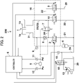
- FIG. 2 is a circuit diagram of the hydraulic drive system in a first embodiment of the present invention.
- the configuration of the hydraulic drive system 200 will be described referring to FIG. 2 .
- the accumulator 4 is a hydraulic apparatus that stores the return fluid from the boom cylinder 1, and supplies the hydraulic fluid at the time of driving the boom cylinder 1.
- the accumulator 4 and the bottom-side fluid chamber 1a of the boom cylinder 1 are connected with each other through a hydraulic fluid line 21, and a control valve 2 and a pilot check valve 8 are disposed in the hydraulic fluid line 21.
- the control valve 2 by receiving a control signal from the controller 6, provides or interrupts communication in the hydraulic fluid line 21.
- the pilot check valve 8 is opened only while a boom lowering pilot pressure Pd described later is generated, and is kept in a closed state when the boom lowering pilot pressure Pd is not generated.
- a pressure sensor 9 for sensing the pressure inside the bottom-side fluid chamber 1a is provided in a line part of the hydraulic fluid line 21, which connects the bottom-side fluid chamber 1a with the pilot check valve 8, and a signal from the pressure sensor 9 is inputted to the controller 6.
- a rod-side fluid chamber 1b of the boom cylinder 1 and the tank 20 are connected with each other by a hydraulic fluid line 22, and a control valve 3 is disposed in the hydraulic fluid line 22.
- the control valve 3, by receiving a control signal from the controller 6, provides or interrupts communication in the hydraulic fluid line 22.
- the rod-side fluid chamber 1b of the boom cylinder 1 and the accumulator 4 are connected with each other by a hydraulic fluid line 23, and a control valve 10 is disposed in the hydraulic fluid line 23.
- the control valve 10 by receiving a control signal from the controller 6, provides or interrupts communication in the hydraulic fluid line 23.
- a hydraulic pump 13 is a hydraulic apparatus mainly for accumulating pressure in the accumulator 4, and a discharge port of the hydraulic pump 13 is connected to the accumulator 4 through a control valve 18 and a hydraulic fluid line 24.
- the control valve 18, by receiving a control signal from the controller 6, is changed over from a normal position depicted in the figure.
- the fluid delivered from the hydraulic pump 13 is discharged to the tank 20, and, when the control valve 18 is changed over from the normal position, the fluid delivered from the hydraulic pump 13 is stored in the accumulator 4.
- a pressure sensor 19 for sensing the pressure inside the accumulator 4 is provided in the hydraulic fluid line 24, and a signal from the pressure sensor 19 is inputted to the controller 6.
- a line part of the hydraulic fluid line 21, which connects the pilot check valve 8 with the control valve 2 is connected through the hydraulic fluid line 24 to a part of the hydraulic fluid line 23, which connects the rod-side fluid chamber 1b with the control valve 10, and a control valve 7 is disposed in the hydraulic fluid line 24.
- the control valve 7 is, by the boom lowering pilot pressure Pd described later, changed over from an interruption position depicted in the figure to a communication position. As a result, at the time of a boom lowering operation, the bottom side of the boom cylinder 1 is made to communicate with the rod side, and the bottom side of the boom cylinder 1 is raised in pressure.
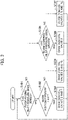
- FIG. 3 represents a control flow concerning driving of the boom cylinder 1
- FIG. 4 represents a control flow concerning a pressure accumulation operation of the accumulator 4.
- the controller 6, first, determines whether or not the boom raising pilot pressure Pu has been sensed by the pressure sensor 12 (step S101).
- step S101 determines whether or not the bottom pressure of the boom cylinder 1 sensed by the pressure sensor 9 is higher than a predetermined pressure set1 (step 102).
- step S102 When the determination in step S102 is Yes (the bottom pressure of the boom cylinder 1 is higher than the predetermined pressure set1), the control valves 2 and 3 are opened while the control valve 10 is kept closed (step S103), and the control returns to step S101.
- the boom cylinder 1 can be put into an extending operation while suppressing a back pressure on the rod side.
- step S102 When the determination in step S102 is No (the bottom pressure of the boom cylinder 1 is equal to or lower than the predetermined pressure set1), the control valves 2 and 10 are opened while the control valve 3 is kept closed (step S104), and the control returns to step S101.
- the boom cylinder 1 can be put into an extending operation while a back pressure is generated on the rod side.
- the pressure difference between the boom cylinder 1 and the accumulator 4 is reduced, and a pressure loss at the time of supplying hydraulic fluid from the accumulator 4 to the boom cylinder 1 is suppressed, so that the boom cylinder 1 can be driven efficiently.
- step S101 When the determination in step S101 is No (the boom raising pilot pressure Pu has not been sensed), it is determined whether or not a boom lowering pilot pressure Pd has been sensed in the pressure sensor 11 (step S105).
- step S105 When the determination in step S105 is Yes (the boom lowering pilot pressure Pd has been sensed), the control valve 2 is opened while the control valves 3 and 10 are kept closed (step S106), and the control returns to step S101.
- the control valve 7 is changed over to a communication position by the boom lowering pilot pressure Pd.
- step S105 When the determination in step S105 is No (the boom lowering pilot pressure Pd has not been sensed), the control valves 2, 3, and 10 are closed (step S107), and the control returns to step S101.
- hydraulic fluid lines for supplying and discharging the hydraulic fluid to and from the boom cylinder 1 are all interrupted, so that the boom cylinder 1 is kept in a standstill state.
- the controller 6, first, determined whether or not the pressure of the accumulator 4 (accumulator pressure) sensed by the pressure sensor 19 is lower than a predetermined pressure set2 (step S201).
- the predetermined pressure set2 here is set at a pressure on the order that the hydraulic fluid can be supplied to the bottom-side fluid chamber 1a of the boom cylinder 1 even in a state in which a back pressure is generated on the rod side by opening the control valve 7.
- step S201 When the determination in step S201 is Yes (the accumulator pressure is lower than the predetermined pressure set2), the control valve 18 is changed over from a normal position and a delivery port of the hydraulic pump 13 is connected to the accumulator 4 (step S202), and the control returns to step S201.
- the fluid delivered from the hydraulic pump 13 is accumulated in the accumulator 4, and the pressure of the accumulator 4 is kept to be equal to or higher than the predetermined pressure set2, and, therefore, the boom cylinder 1 can be driven at an optional timing.
- step S201 When the determination in step S201 is No (the accumulator pressure is equal to or higher than the predetermined pressure set 2), the control valve 18 is returned to the normal position and the delivery port of the hydraulic pump 13 is connected to the tank 20 (step S202), and the control returns to S201.
- pressure accumulation in the accumulator 4 is not caused more than necessary by the hydraulic pump 13, and, therefore, needless energy consumption can be restrained.
- the controller 6 determines that a boom raising pilot pressure Pu has been sensed, opens the control valve 2 and opens either one of the control valves 3 and 10 according to the bottom pressure of the boom cylinder 1. Specifically, where the bottom pressure of the boom cylinder 1 is higher than the predetermined pressure set1, the control valve 3 is opened while the control valve 10 is kept closed to thereby suppress the back pressure on the rod side, whereby the boom cylinder 1 is extended efficiently. In this instance, since the pressure difference between the pressure in the accumulator 4 and the bottom pressure is small, a large pressure loss is not generated in the control valve 2.
- the control valve 10 is opened while the control valve 3 is kept closed to thereby connect the rod side of the boom cylinder 1 to the accumulator 4, and to generate a back pressure on the rod side.
- the pressure on the bottom side in the boom cylinder 1 is also raised, the pressure difference between the bottom side of the boom cylinder 1 and the accumulator 4 is reduced, so that a pressure loss generated in the control valve 2 can be reduced.
- the back pressure generated on the rod side in the boom cylinder 1 is regenerated as it is in the accumulator 4 through the control valve 10, energy loss due to generation of the back pressure is not generated.
- the construction machine 100 including the tank 20 that reserves the hydraulic fluid, the hydraulic cylinder 1, the accumulator 4 that accumulates the return fluid from the hydraulic cylinder 1, the first control valve 2 disposed in the first hydraulic fluid line 21 connecting the bottom-side fluid chamber 1a of the hydraulic cylinder 1 with the accumulator 4, and the second control valve 3 disposed in the second hydraulic fluid line 22 connecting the rod-side fluid chamber 1b of the hydraulic cylinder 1 with the tank 2, includes the third control valve 10 disposed in the third hydraulic fluid line 23 connecting the rod-side fluid chamber 1b with the accumulator 4, and the fourth control valve 7 disposed in the fourth hydraulic fluid line 24 connecting a line part of the first hydraulic fluid line 21, which connects the bottom-side fluid chamber 1a with the first control valve 2, and a line part of the third hydraulic fluid line 23, which connects the rod-side fluid chamber with the third control valve 10, with each other.
- the fourth control valve 7 is opened to cause the bottom side of the hydraulic cylinder 1 to communicate with the rod side to thereby raise the bottom side
- the first control valve 2 is opened to cause the bottom side to communicate with the accumulator 4, whereby the return fluid from the bottom side can be accumulated at a high pressure in the accumulator 4.
- the fourth control valve 7 is closed to interrupt the communication between the bottom side and the rod side of the hydraulic cylinder 1, and the first control valve 2 is opened to cause the bottom side to communicate with the accumulator 4, and either one of the second control valve 3 and the third control valve 10 is opened, whereby hydraulic fluid can be supplied from the accumulator 4 to the bottom side while adjusting the back pressure on the rod side.
- the pressure difference between the accumulator 4 and the bottom side of the hydraulic cylinder 1 can be reduced, and, therefore, pressure loss at the first control valve 2 can be reduced.
- the construction machine 100 includes the operation lever 5 for issuing an instruction on an operation of the hydraulic cylinder 1, and the controller 6 that performs such a control as to open the first control valve 2 and to open either one of the second control valve 3 and the third control valve 10 when an extending operation of the hydraulic cylinder 1 is instructed through the operation lever 5, in which the controller 6 performs such a control as to close the fourth control valve 7 when the extending operation of the hydraulic cylinder 1 is instructed through the operation lever 5, and to open the fourth control valve 7 when a shrinking operation of the hydraulic cylinder 1 is instructed through the operation lever 5.
- the fourth control valve 7 is opened to cause the bottom side of the hydraulic cylinder 1 to communicate with the rod side and be raised in pressure
- the first control valve 2 is opened to cause the bottom side to communicate with the accumulator 4, so that the return fluid on the bottom side can be accumulated at high pressure in the accumulator 4.
- the fourth control valve 7 is closed to thereby interrupt the communication between the bottom side and the rod side of the hydraulic cylinder 1, and either one of the second control valve 3 and the third control valve 10 is opened to cause the rod side to communicate with the tank 20 or the accumulator 4, so that a back pressure on the rod side can be adjusted.
- the construction machine 100 includes the first pressure sensor 9 for sensing the pressure in the bottom-side fluid chamber 1a, in which the controller 6 performs such a control as to close the third control valve and to open the second control valve 3 when the extending operation of the hydraulic cylinder 1 is instructed through the operation lever 5 and when the pressure in the bottom-side fluid chamber 1a sensed by the first pressure sensor 9 is higher than the first predetermined pressure set1, and as to close the second control valve and to open the third control valve 10 when the extending operation of the hydraulic cylinder 1 is instructed through the operation lever 5 and when the pressure in the bottom-side fluid chamber 1a sensed by the first pressure sensor 9 is equal to or lower than the first predetermined pressure set1.
- the controller 6 performs such a control as to close the third control valve and to open the second control valve 3 when the extending operation of the hydraulic cylinder 1 is instructed through the operation lever 5 and when the pressure in the bottom-side fluid chamber 1a sensed by the first pressure sensor 9 is higher than the first predetermined pressure set1, and as to close the second control valve and to open
- the rod side is made to communicate with the accumulator 4 to generate a back pressure, and the pressure difference between the accumulator 4 and the bottom side of the hydraulic cylinder 1 is reduced, whereby pressure loss in the control valve 2 can be reduced.
- the rod side is made to communicate with the tank 20 to suppress a back pressure, whereby the hydraulic cylinder 1 can be put into the extending operation efficiently.
- the construction machine 100 includes the hydraulic pump 13, the fifth control valve 18 that selectively connects the delivery port of the hydraulic pump 13 to the accumulator 4 or the tank 20, and the second pressure sensor 19 for sensing the pressure in the accumulator 4, in which the controller 6 controls the fifth control valve 18 such that the delivery port of the hydraulic pump 13 is connected to the tank 20 when the pressure in the accumulator 4 sensed by the second pressure sensor 19 is equal to or higher than the second predetermined pressure set2, and controls the fifth control valve 18 such that the delivery port of the hydraulic pump 13 is connected to the accumulator 4 when the pressure in the accumulator 4 sensed by the second pressure sensor 19 is lower than the second predetermined pressure set2.
- the pressure in the accumulator 4 is kept equal to or higher than the second predetermined pressure set2, and, therefore, the hydraulic cylinder 1 can be driven at an optional timing.
- FIG. 5 is a circuit diagram of a hydraulic drive system according to a second embodiment of the present invention.
- the hydraulic drive system 200 includes a directional control valve 14 for supplying the fluid delivered from the hydraulic pump 13 to the boom cylinder 1, and for making the hydraulic fluid discharged from the boom cylinder 1 flow to the tank.
- the directional control valve 14 is changed over from a neutral position in the figure to a left side position by the boom raising pilot pressure Pu, and is changed over from the neutral position to the right side position by the boom lowering pilot pressure Pd.
- the directional control valve 14 changed over to the left side position causes the delivery port of the hydraulic pump 13 to communicate with the bottom-side fluid chamber 1a of the boom cylinder 1, and causes the rod-side fluid chamber 1b to communicate with the tank 20.
- the directional control valve 14 changed over to the right side position causes the bottom-side fluid chamber 1a of the boom cylinder 1 to communicate with the rod-side fluid chamber 1b.
- the functions of the control valve 7 (depicted in FIG. 2 ) in the first embodiment are mounted to the right side position of the directional control valve 14.
- the pilot check valve 15 is disposed between the directional control valve 14 and the hydraulic cylinder 1, and the directional control valve 14 and the pilot check valve 15 are configured as a united valve block 17, whereas the other valves are configured as a valve block 16.
- the valve block 17 configures a main control valve which has been mounted on a conventional hydraulic excavator and which is for controlling the supply of hydraulic fluid from the hydraulic pump to the actuator, whereas the valve block 16 is configured as a hybrid valve for controlling the supply of hydraulic fluid to the accumulator.
- the construction machine 100 includes the hydraulic pump 13, and the fourth control valve 14 is the directional control valve 14 capable of supplying the hydraulic fluid delivered from the hydraulic pump 13 to the hydraulic cylinder 1 and capable of discharging the return fluid from the hydraulic cylinder 1 to the tank 20.
- the function of causing the bottom side of the boom cylinder 1 to communicate with the rod side and to be raised in pressure is mounted at a right side position of the directional control valve 14, whereby the control valve 7 (depicted in FIG. 2 ) in the first embodiment is made unnecessary.
- the hydraulic fluid can be supplied from the hydraulic pump 13 to the hydraulic cylinder 1 through the directional control valve 14, whereby charging of the accumulator 4 is made to be unnecessary, and, therefore, the control valve 18 and the pressure sensor 19 (depicted in FIG. 2 ) in the first embodiment are also made unnecessary.
- the hydraulic circuit can be prevented from becoming complicated.
- the construction machine 100 includes: the first pilot check valve 8 disposed at a line part of the first hydraulic fluid line 21, which connects the bottom-side fluid chamber 1a with the first control valve 2; the second pilot check valve 15 disposed in a line part of the fourth hydraulic fluid line 24, which connects the bottom-side fluid chamber 1a with the directional control valve 14; the first valve block 16 which unites together the first control valve 2, the second control valve 3, the third control valve 10, and the first pilot check valve 8; and the second valve block 17 which unites together the directional control valve 14 and the second pilot check valve 15.
- the construction machine can be hybridized by only adding on a hybrid valve to the conventional main control valve, and leak of the boom cylinder 1 can be securely prevented by the pilot check valves 8 and 15 provided respectively in the main control valve and the hybrid valve.
- the present invention is not limited to the above-described embodiments, and includes various modifications.
- the above embodiments have been described in detail for easily understandably explaining the present invention, and are not limited to those which include all the described configurations.
- a part of the configuration of another embodiment can be added, or a part of the configuration of an embodiment can be deleted or can be replaced by a part of another embodiment.
Landscapes
- Engineering & Computer Science (AREA)
- General Engineering & Computer Science (AREA)
- Mining & Mineral Resources (AREA)
- Civil Engineering (AREA)
- Structural Engineering (AREA)
- Physics & Mathematics (AREA)
- Fluid Mechanics (AREA)
- Mechanical Engineering (AREA)
- Operation Control Of Excavators (AREA)
- Fluid-Pressure Circuits (AREA)
- Hydrogenated Pyridines (AREA)
Abstract
Description
- The present invention relates to a construction machine such as a hydraulic excavator.
- According to
Patent Document 1, the bottom side and the rod side of the boom cylinder are made to communicate with each other at the time of a boom lowering operation, and further the bottom side is connected to the accumulator, whereby the return fluid from the boom cylinder can be accumulated in the accumulator with a rise in pressure. Further, inPatent Document 2, the hydraulic fluid accumulated in the accumulator is supplied to the boom cylinder, and the flow rate to the boom cylinder from a pump is reduced accordingly, whereby fuel cost can be reduced. -
- Patent Document 1:
JP-2009-275769-A - Patent Document 2:
JP-2009-275771-A - However, according to the configurations of
Patent Document 1 andPatent Document 2, pressure accumulation of the accumulator is conducted by raising the bottom pressure of the boom cylinder, so that the pressure of the accumulator is also raised. When the hydraulic fluid is supplied to the boom cylinder from the accumulator in which pressure accumulation has been thus conducted to a high pressure, a large pressure loss is generated, and there is a fear that the energy accumulated in the accumulator may not be effectively usable. Here, the bottom pressure of the boom cylinder varies according to the posture of the front implement including the arm and the bucket. For example, in the crowding posture of the arm and the bucket, the bottom pressure of the boom is lowered. If the hydraulic fluid is supplied to the bottom side of the boom cylinder from the accumulator in that state, a large pressure loss is generated. - The present invention has been made in consideration of the above problem. It is an object of the present invention to provide a construction machine capable of efficiently driving a hydraulic cylinder by an accumulator.
- To achieve the above object, according to the present invention, there is provided a construction machine including: a tank that reserves a hydraulic fluid; a hydraulic cylinder; an accumulator that accumulates a return fluid from the hydraulic cylinder; a first control valve disposed in a first hydraulic fluid line connecting a bottom-side fluid chamber of the hydraulic cylinder with the accumulator; and a second control valve disposed in a second hydraulic fluid line connecting a rod-side fluid chamber of the hydraulic cylinder with the tank, in which the construction machine further includes: a third control valve disposed in a third hydraulic fluid line connecting the rod-side fluid chamber with the accumulator; and a fourth control valve disposed in a fourth hydraulic fluid line connecting a line part of the first hydraulic fluid line, the line part connecting the bottom-side fluid chamber with the first control valve, and a line part of the third hydraulic fluid line, the line part connecting the rod-side fluid chamber with the third control valve, with each other.
- According to the present invention configured as above, at the time of shrinking driving of the hydraulic cylinder, the fourth control valve is opened to cause the bottom side of the hydraulic cylinder to communicate with the rod side and raise the pressure on the bottom side, and the first control valve is opened to cause the bottom side to communicate with the
accumulator 4, whereby the return fluid from the bottom side can be accumulated in the accumulator at a high pressure. In addition, at the time of driving of the hydraulic cylinder to extend, the fourth control valve is closed to interrupt the communication between the bottom side and the rod side of the hydraulic cylinder, and the first control valve is opened to cause the bottom side to communicate with the accumulator, and either one of the second control valve and the third control valve is opened, whereby the hydraulic fluid can be supplied from the accumulator to the bottom side while adjusting a back pressure on the rod side. As a result, the pressure difference between the accumulator and the bottom side of thehydraulic cylinder 1 can be reduced, so that pressure loss at the first control valve can be reduced. - According to the construction machine of the present invention, the hydraulic cylinder can be efficiently driven by the accumulator.
-
-
FIG. 1 is a side view of a hydraulic excavator according to embodiments of the present invention. -
FIG. 2 is a circuit diagram of a hydraulic drive system according to a first embodiment of the present invention. -
FIG. 3 is a diagram depicting a control flow according to driving of a boom cylinder by a controller in the first embodiment of the present invention. -
FIG. 4 is a diagram depicting a control flow according to a pressure accumulation operation of an accumulator by the controller in the first embodiment of the present invention. -
FIG. 5 is a circuit diagram of a hydraulic drive system in a second embodiment of the present invention. - A construction machine according to embodiments of the present invention will be described, taking a hydraulic excavator as an example of the construction machine and referring to the drawings. Note that in each drawing, equivalent members are denoted by the same reference characters and overlapping descriptions will be omitted as required.
-
FIG. 1 is a side view of a hydraulic excavator according to the present embodiments. - As depicted in
FIG. 1 , thehydraulic excavator 100 includes atrack structure 101, aswing structure 102 swingably disposed on thetrack structure 101 to constitute a machine body, and awork device 103 which is mounted to theswing structure 102 in a vertically rotatable manner and which performs excavation work of soil or the like. Theswing structure 102 is driven by aswing motor 104. - The
work device 103 includes aboom 105 mounted to theswing structure 102 in a vertically rotatable manner, anarm 106 mounted to the tip of theboom 105 in a vertically rotatable manner, and abucket 107 mounted to the tip of thearm 106 in a vertically rotatable manner. Theboom 105 is driven by aboom cylinder 1, thearm 106 is driven by anarm cylinder 108, and thebucket 107 is driven by abucket cylinder 109. - A
cab 110 is provided at a front side position of theswing structure 102, and acounter weight 111 for securing weight balance is provided at a rear side position. Amachine room 112 is provided between thecab 110 and thecounter weight 111, and an engine, a hydraulic pump, acontrol valve 113, and the like are accommodated in themachine room 112. Thecontrol valve 113 controls the flow of a hydraulic fluid supplied from the hydraulic pump to each actuator. - The
hydraulic excavator 100 according to the present embodiment has mounted thereon a hydraulic drive system described in each of the following embodiments. -
FIG. 2 is a circuit diagram of the hydraulic drive system in a first embodiment of the present invention. - The configuration of the
hydraulic drive system 200 will be described referring toFIG. 2 . - The
accumulator 4 is a hydraulic apparatus that stores the return fluid from theboom cylinder 1, and supplies the hydraulic fluid at the time of driving theboom cylinder 1. Theaccumulator 4 and the bottom-side fluid chamber 1a of theboom cylinder 1 are connected with each other through ahydraulic fluid line 21, and acontrol valve 2 and a pilot check valve 8 are disposed in thehydraulic fluid line 21. Thecontrol valve 2, by receiving a control signal from thecontroller 6, provides or interrupts communication in thehydraulic fluid line 21. The pilot check valve 8 is opened only while a boom lowering pilot pressure Pd described later is generated, and is kept in a closed state when the boom lowering pilot pressure Pd is not generated. As a result, exclusive of the time of a boom lowering operation, the pressure inside the bottom-side fluid chamber 1a of theboom cylinder 1 is maintained, so that an unintended shrinking operation of theboom cylinder 1 can be prevented. Apressure sensor 9 for sensing the pressure inside the bottom-side fluid chamber 1a is provided in a line part of thehydraulic fluid line 21, which connects the bottom-side fluid chamber 1a with the pilot check valve 8, and a signal from thepressure sensor 9 is inputted to thecontroller 6. - A rod-
side fluid chamber 1b of theboom cylinder 1 and thetank 20 are connected with each other by ahydraulic fluid line 22, and acontrol valve 3 is disposed in thehydraulic fluid line 22. Thecontrol valve 3, by receiving a control signal from thecontroller 6, provides or interrupts communication in thehydraulic fluid line 22. - The rod-
side fluid chamber 1b of theboom cylinder 1 and theaccumulator 4 are connected with each other by ahydraulic fluid line 23, and acontrol valve 10 is disposed in thehydraulic fluid line 23. Thecontrol valve 10, by receiving a control signal from thecontroller 6, provides or interrupts communication in thehydraulic fluid line 23. - A
hydraulic pump 13 is a hydraulic apparatus mainly for accumulating pressure in theaccumulator 4, and a discharge port of thehydraulic pump 13 is connected to theaccumulator 4 through acontrol valve 18 and ahydraulic fluid line 24. Thecontrol valve 18, by receiving a control signal from thecontroller 6, is changed over from a normal position depicted in the figure. When thecontrol valve 18 is in the normal position, the fluid delivered from thehydraulic pump 13 is discharged to thetank 20, and, when thecontrol valve 18 is changed over from the normal position, the fluid delivered from thehydraulic pump 13 is stored in theaccumulator 4. Apressure sensor 19 for sensing the pressure inside theaccumulator 4 is provided in thehydraulic fluid line 24, and a signal from thepressure sensor 19 is inputted to thecontroller 6. - A line part of the
hydraulic fluid line 21, which connects the pilot check valve 8 with thecontrol valve 2, is connected through thehydraulic fluid line 24 to a part of thehydraulic fluid line 23, which connects the rod-side fluid chamber 1b with thecontrol valve 10, and a control valve 7 is disposed in thehydraulic fluid line 24. The control valve 7 is, by the boom lowering pilot pressure Pd described later, changed over from an interruption position depicted in the figure to a communication position. As a result, at the time of a boom lowering operation, the bottom side of theboom cylinder 1 is made to communicate with the rod side, and the bottom side of theboom cylinder 1 is raised in pressure. - When the
operation lever 5 is operated in a boom raising direction by an operator, a boom raising pilot pressure Pu is generated, whereas when theoperation lever 5 is operated in a boom lowering direction, the boom lowering pilot pressure Pd is generated. The boom lowering pilot pressure Pd is sensed by apressure sensor 11, whereas the boom raising pilot pressure Pu is sensed by apressure sensor 12, and signals from thepressure sensors controller 6. - Next, the contents of processing of the
controller 6 will be described usingFIGS. 3 and4 .FIG. 3 represents a control flow concerning driving of theboom cylinder 1, andFIG. 4 represents a control flow concerning a pressure accumulation operation of theaccumulator 4. These control flows are started, for example, when a key-switch not illustrated is turned ON, and are simultaneously carried out concurrently. - First, referring to
FIG. 3 , a control flow concerning driving of theboom cylinder 1 will be described. - The
controller 6, first, determines whether or not the boom raising pilot pressure Pu has been sensed by the pressure sensor 12 (step S101). - When the determination in step S101 is Yes (the boom raising pilot pressure Pu has been sensed), it is determined whether or not the bottom pressure of the
boom cylinder 1 sensed by thepressure sensor 9 is higher than a predetermined pressure set1 (step 102). - When the determination in step S102 is Yes (the bottom pressure of the
boom cylinder 1 is higher than the predetermined pressure set1), thecontrol valves control valve 10 is kept closed (step S103), and the control returns to step S101. By this, theboom cylinder 1 can be put into an extending operation while suppressing a back pressure on the rod side. - When the determination in step S102 is No (the bottom pressure of the
boom cylinder 1 is equal to or lower than the predetermined pressure set1), thecontrol valves control valve 3 is kept closed (step S104), and the control returns to step S101. By this, theboom cylinder 1 can be put into an extending operation while a back pressure is generated on the rod side. In this instance, the pressure difference between theboom cylinder 1 and theaccumulator 4 is reduced, and a pressure loss at the time of supplying hydraulic fluid from theaccumulator 4 to theboom cylinder 1 is suppressed, so that theboom cylinder 1 can be driven efficiently. - When the determination in step S101 is No (the boom raising pilot pressure Pu has not been sensed), it is determined whether or not a boom lowering pilot pressure Pd has been sensed in the pressure sensor 11 (step S105).
- When the determination in step S105 is Yes (the boom lowering pilot pressure Pd has been sensed), the
control valve 2 is opened while thecontrol valves boom cylinder 1 is accumulated into the accumulator through thecontrol valve 2, whereas a remaining part of the hydraulic fluid is supplied to the rod side of theboom cylinder 1 through the control valve 7, and theboom cylinder 1 is put into a shrinking operation. - When the determination in step S105 is No (the boom lowering pilot pressure Pd has not been sensed), the
control valves boom cylinder 1 are all interrupted, so that theboom cylinder 1 is kept in a standstill state. - Next, referring to
FIG. 4 , a control flow concerning a pressure accumulation operation of theaccumulator 4 will be described. - The
controller 6, first, determined whether or not the pressure of the accumulator 4 (accumulator pressure) sensed by thepressure sensor 19 is lower than a predetermined pressure set2 (step S201). The predetermined pressure set2 here is set at a pressure on the order that the hydraulic fluid can be supplied to the bottom-side fluid chamber 1a of theboom cylinder 1 even in a state in which a back pressure is generated on the rod side by opening the control valve 7. - When the determination in step S201 is Yes (the accumulator pressure is lower than the predetermined pressure set2), the
control valve 18 is changed over from a normal position and a delivery port of thehydraulic pump 13 is connected to the accumulator 4 (step S202), and the control returns to step S201. As a result, the fluid delivered from thehydraulic pump 13 is accumulated in theaccumulator 4, and the pressure of theaccumulator 4 is kept to be equal to or higher than the predetermined pressure set2, and, therefore, theboom cylinder 1 can be driven at an optional timing. - When the determination in step S201 is No (the accumulator pressure is equal to or higher than the predetermined pressure set 2), the
control valve 18 is returned to the normal position and the delivery port of thehydraulic pump 13 is connected to the tank 20 (step S202), and the control returns to S201. By this, pressure accumulation in theaccumulator 4 is not caused more than necessary by thehydraulic pump 13, and, therefore, needless energy consumption can be restrained. - Referring to
FIG. 2 , an operation of thehydraulic drive system 200 will be described. - First, a lowering operation of the boom 105 (a shrinking operation of the boom cylinder 1) will be described.
- When the
operation lever 5 is operated in a boom lowering direction, holding of pressure in the pilot check valve 8 is released by the boom lowering pilot pressure Pd and the control valve 7 is opened, and the bottom side of theboom cylinder 1 is made to communicate with the rod side and is raised in pressure. In addition, simultaneously, thecontroller 6 opens thecontrol valve 2, whereby the hydraulic fluid on the bottom side flows into theaccumulator 4 to regenerate energy, and theboom cylinder 1 shrinks. In this instance, pressure accumulation in theaccumulator 4 is caused by the raised bottom pressure. - Next, a raising operation of the boom 105 (an extending operation of the boom cylinder 1) will be described.
- When the
operation lever 5 is operated in a boom raising direction, thecontroller 6 determines that a boom raising pilot pressure Pu has been sensed, opens thecontrol valve 2 and opens either one of thecontrol valves boom cylinder 1. Specifically, where the bottom pressure of theboom cylinder 1 is higher than the predetermined pressure set1, thecontrol valve 3 is opened while thecontrol valve 10 is kept closed to thereby suppress the back pressure on the rod side, whereby theboom cylinder 1 is extended efficiently. In this instance, since the pressure difference between the pressure in theaccumulator 4 and the bottom pressure is small, a large pressure loss is not generated in thecontrol valve 2. On the other hand, when the bottom pressure of theboom cylinder 1 is equal to or lower than the predetermined pressure set1, thecontrol valve 10 is opened while thecontrol valve 3 is kept closed to thereby connect the rod side of theboom cylinder 1 to theaccumulator 4, and to generate a back pressure on the rod side. As a result, since the pressure on the bottom side in theboom cylinder 1 is also raised, the pressure difference between the bottom side of theboom cylinder 1 and theaccumulator 4 is reduced, so that a pressure loss generated in thecontrol valve 2 can be reduced. In this instance, since the back pressure generated on the rod side in theboom cylinder 1 is regenerated as it is in theaccumulator 4 through thecontrol valve 10, energy loss due to generation of the back pressure is not generated. - In the present embodiment, the
construction machine 100 including thetank 20 that reserves the hydraulic fluid, thehydraulic cylinder 1, theaccumulator 4 that accumulates the return fluid from thehydraulic cylinder 1, thefirst control valve 2 disposed in the firsthydraulic fluid line 21 connecting the bottom-side fluid chamber 1a of thehydraulic cylinder 1 with theaccumulator 4, and thesecond control valve 3 disposed in the secondhydraulic fluid line 22 connecting the rod-side fluid chamber 1b of thehydraulic cylinder 1 with thetank 2, includes thethird control valve 10 disposed in the thirdhydraulic fluid line 23 connecting the rod-side fluid chamber 1b with theaccumulator 4, and the fourth control valve 7 disposed in the fourthhydraulic fluid line 24 connecting a line part of the firsthydraulic fluid line 21, which connects the bottom-side fluid chamber 1a with thefirst control valve 2, and a line part of the thirdhydraulic fluid line 23, which connects the rod-side fluid chamber with thethird control valve 10, with each other. - According to the present embodiment configured as above, at the time of driving the
hydraulic cylinder 1 to shrink, the fourth control valve 7 is opened to cause the bottom side of thehydraulic cylinder 1 to communicate with the rod side to thereby raise the bottom side, and thefirst control valve 2 is opened to cause the bottom side to communicate with theaccumulator 4, whereby the return fluid from the bottom side can be accumulated at a high pressure in theaccumulator 4. In addition, at the time of driving thehydraulic cylinder 1 to extend, the fourth control valve 7 is closed to interrupt the communication between the bottom side and the rod side of thehydraulic cylinder 1, and thefirst control valve 2 is opened to cause the bottom side to communicate with theaccumulator 4, and either one of thesecond control valve 3 and thethird control valve 10 is opened, whereby hydraulic fluid can be supplied from theaccumulator 4 to the bottom side while adjusting the back pressure on the rod side. As a result, the pressure difference between theaccumulator 4 and the bottom side of thehydraulic cylinder 1 can be reduced, and, therefore, pressure loss at thefirst control valve 2 can be reduced. - In addition, the
construction machine 100 according to the present embodiment includes theoperation lever 5 for issuing an instruction on an operation of thehydraulic cylinder 1, and thecontroller 6 that performs such a control as to open thefirst control valve 2 and to open either one of thesecond control valve 3 and thethird control valve 10 when an extending operation of thehydraulic cylinder 1 is instructed through theoperation lever 5, in which thecontroller 6 performs such a control as to close the fourth control valve 7 when the extending operation of thehydraulic cylinder 1 is instructed through theoperation lever 5, and to open the fourth control valve 7 when a shrinking operation of thehydraulic cylinder 1 is instructed through theoperation lever 5. - With such a configuration, where the shrinking operation of the
hydraulic cylinder 1 is instructed through theoperation lever 5, the fourth control valve 7 is opened to cause the bottom side of thehydraulic cylinder 1 to communicate with the rod side and be raised in pressure, and thefirst control valve 2 is opened to cause the bottom side to communicate with theaccumulator 4, so that the return fluid on the bottom side can be accumulated at high pressure in theaccumulator 4. In addition, where the extending operation of thehydraulic cylinder 1 is instructed through theoperation lever 5, the fourth control valve 7 is closed to thereby interrupt the communication between the bottom side and the rod side of thehydraulic cylinder 1, and either one of thesecond control valve 3 and thethird control valve 10 is opened to cause the rod side to communicate with thetank 20 or theaccumulator 4, so that a back pressure on the rod side can be adjusted. - Besides, the
construction machine 100 according to the present embodiment includes thefirst pressure sensor 9 for sensing the pressure in the bottom-side fluid chamber 1a, in which thecontroller 6 performs such a control as to close the third control valve and to open thesecond control valve 3 when the extending operation of thehydraulic cylinder 1 is instructed through theoperation lever 5 and when the pressure in the bottom-side fluid chamber 1a sensed by thefirst pressure sensor 9 is higher than the first predetermined pressure set1, and as to close the second control valve and to open thethird control valve 10 when the extending operation of thehydraulic cylinder 1 is instructed through theoperation lever 5 and when the pressure in the bottom-side fluid chamber 1a sensed by thefirst pressure sensor 9 is equal to or lower than the first predetermined pressure set1. - With such a configuration, where the extending operation of the
hydraulic cylinder 1 is instructed through theoperation lever 5 and where the pressure in the bottom-side fluid chamber 1a is higher than the first predetermined pressure set1, the rod side is made to communicate with theaccumulator 4 to generate a back pressure, and the pressure difference between theaccumulator 4 and the bottom side of thehydraulic cylinder 1 is reduced, whereby pressure loss in thecontrol valve 2 can be reduced. Besides, where the extending operation of thehydraulic cylinder 1 is instructed through theoperation lever 5 and where the pressure in the bottom-side fluid chamber 1a is equal to or lower than the first predetermined pressure set1, the rod side is made to communicate with thetank 20 to suppress a back pressure, whereby thehydraulic cylinder 1 can be put into the extending operation efficiently. - In addition, the
construction machine 100 according to the present embodiment includes thehydraulic pump 13, thefifth control valve 18 that selectively connects the delivery port of thehydraulic pump 13 to theaccumulator 4 or thetank 20, and thesecond pressure sensor 19 for sensing the pressure in theaccumulator 4, in which thecontroller 6 controls thefifth control valve 18 such that the delivery port of thehydraulic pump 13 is connected to thetank 20 when the pressure in theaccumulator 4 sensed by thesecond pressure sensor 19 is equal to or higher than the second predetermined pressure set2, and controls thefifth control valve 18 such that the delivery port of thehydraulic pump 13 is connected to theaccumulator 4 when the pressure in theaccumulator 4 sensed by thesecond pressure sensor 19 is lower than the second predetermined pressure set2. - With such a configuration, the pressure in the
accumulator 4 is kept equal to or higher than the second predetermined pressure set2, and, therefore, thehydraulic cylinder 1 can be driven at an optional timing. -
FIG. 5 is a circuit diagram of a hydraulic drive system according to a second embodiment of the present invention. - The
hydraulic drive system 200 according to the present embodiment includes adirectional control valve 14 for supplying the fluid delivered from thehydraulic pump 13 to theboom cylinder 1, and for making the hydraulic fluid discharged from theboom cylinder 1 flow to the tank. Thedirectional control valve 14 is changed over from a neutral position in the figure to a left side position by the boom raising pilot pressure Pu, and is changed over from the neutral position to the right side position by the boom lowering pilot pressure Pd. Thedirectional control valve 14 changed over to the left side position causes the delivery port of thehydraulic pump 13 to communicate with the bottom-side fluid chamber 1a of theboom cylinder 1, and causes the rod-side fluid chamber 1b to communicate with thetank 20. Thedirectional control valve 14 changed over to the right side position causes the bottom-side fluid chamber 1a of theboom cylinder 1 to communicate with the rod-side fluid chamber 1b. Thus, the functions of the control valve 7 (depicted inFIG. 2 ) in the first embodiment are mounted to the right side position of thedirectional control valve 14. - Further, in the present embodiment, the
pilot check valve 15 is disposed between thedirectional control valve 14 and thehydraulic cylinder 1, and thedirectional control valve 14 and thepilot check valve 15 are configured as aunited valve block 17, whereas the other valves are configured as avalve block 16. In other words, thevalve block 17 configures a main control valve which has been mounted on a conventional hydraulic excavator and which is for controlling the supply of hydraulic fluid from the hydraulic pump to the actuator, whereas thevalve block 16 is configured as a hybrid valve for controlling the supply of hydraulic fluid to the accumulator. - The
construction machine 100 according to the present embodiment includes thehydraulic pump 13, and thefourth control valve 14 is thedirectional control valve 14 capable of supplying the hydraulic fluid delivered from thehydraulic pump 13 to thehydraulic cylinder 1 and capable of discharging the return fluid from thehydraulic cylinder 1 to thetank 20. - According to the present embodiment configured as above, the following effects can be obtained in addition to the effects of the first embodiment.
- The function of causing the bottom side of the
boom cylinder 1 to communicate with the rod side and to be raised in pressure is mounted at a right side position of thedirectional control valve 14, whereby the control valve 7 (depicted inFIG. 2 ) in the first embodiment is made unnecessary. Besides, the hydraulic fluid can be supplied from thehydraulic pump 13 to thehydraulic cylinder 1 through thedirectional control valve 14, whereby charging of theaccumulator 4 is made to be unnecessary, and, therefore, thecontrol valve 18 and the pressure sensor 19 (depicted inFIG. 2 ) in the first embodiment are also made unnecessary. As a result, the hydraulic circuit can be prevented from becoming complicated. - In addition, the
construction machine 100 according to the present embodiment includes: the first pilot check valve 8 disposed at a line part of the firsthydraulic fluid line 21, which connects the bottom-side fluid chamber 1a with thefirst control valve 2; the secondpilot check valve 15 disposed in a line part of the fourthhydraulic fluid line 24, which connects the bottom-side fluid chamber 1a with thedirectional control valve 14; thefirst valve block 16 which unites together thefirst control valve 2, thesecond control valve 3, thethird control valve 10, and the first pilot check valve 8; and thesecond valve block 17 which unites together thedirectional control valve 14 and the secondpilot check valve 15. - With such a configuration, the construction machine can be hybridized by only adding on a hybrid valve to the conventional main control valve, and leak of the
boom cylinder 1 can be securely prevented by thepilot check valves 8 and 15 provided respectively in the main control valve and the hybrid valve. - While the embodiments of the present invention have been described in detail above, the present invention is not limited to the above-described embodiments, and includes various modifications. For example, the above embodiments have been described in detail for easily understandably explaining the present invention, and are not limited to those which include all the described configurations. In addition, to the configuration of an embodiment, a part of the configuration of another embodiment can be added, or a part of the configuration of an embodiment can be deleted or can be replaced by a part of another embodiment.
-
- 1: Boom cylinder (hydraulic cylinder)
- 2: Control valve (first control valve)
- 3: Control valve (second control valve)
- 4: Accumulator
- 5: Operation lever
- 6: Controller
- 7: Control valve (fourth control valve)
- 8: Pilot check valve (first pilot check valve)
- 9: Pressure sensor (first pressure sensor)
- 10: Control valve (third control valve)
- 11: Pressure sensor
- 12: Pressure sensor
- 13: Hydraulic pump
- 14: Directional control valve (fourth control valve)
- 15: Pilot check valve (second pilot check valve)
- 16: Valve block (first valve block)
- 17: Valve block (second valve block)
- 18: Control valve (fifth control valve)
- 19: Pressure sensor (second pressure sensor)
- 20: Tank
- 21: Hydraulic fluid line (first hydraulic fluid line)
- 22: Hydraulic fluid line (second hydraulic fluid line)
- 23: Hydraulic fluid line (third hydraulic fluid line)
- 24: Hydraulic fluid line (fourth hydraulic fluid line)
- 25: Hydraulic fluid line
- 26: Control valve
- 100: Hydraulic excavator (construction machine)
- 101: Track structure
- 102: Swing structure
- 103: Work device
- 104: Swing motor
- 105: Boom
- 106: Arm
- 107: Bucket
- 108: Arm cylinder
- 109: Bucket cylinder
- 110: Cab
- 111: Counter weight
- 112: Machine room
- 113: Control valve
- 200: Hydraulic drive system
Claims (6)
- A construction machine comprising:a tank that reserves a hydraulic fluid;a hydraulic cylinder;an accumulator that accumulates a return fluid from the hydraulic cylinder;a first control valve disposed in a first hydraulic fluid line connecting a bottom-side fluid chamber of the hydraulic cylinder with the accumulator; anda second control valve disposed in a second hydraulic fluid line connecting a rod-side fluid chamber of the hydraulic cylinder with the tank, whereinthe construction machine includesa third control valve disposed in a third hydraulic fluid line connecting the rod-side fluid chamber with the accumulator, anda fourth control valve disposed in a fourth hydraulic fluid line connecting a line part of the first hydraulic fluid line, the line part connecting the bottom-side fluid chamber with the first control valve, and a line part of the third hydraulic fluid line, the line part connecting the rod-side fluid chamber with the third control valve, with each other.
- The construction machine according to claim 1, including:an operation lever for issuing an instruction on an operation of the hydraulic cylinder; anda controller that performs such a control as to open the first control valve and to open either one of the second control valve and the third control valve in a case where an extending operation of the hydraulic cylinder is instructed through the operation lever, whereinthe controller is configured to perform such a control as to close the fourth control valve in a case where an extending operation of the hydraulic cylinder is instructed through the operation lever, and as to open the fourth control valve in a case where a shrinking operation of the hydraulic cylinder is instructed through the operation lever.
- The construction machine according to claim 2, including a first pressure sensor that senses a pressure inside the bottom-side fluid chamber, wherein
the controller is configured perform such a control as to close the third control valve and to open the second control valve in a case where an extending operation of the hydraulic cylinder is instructed through the operation lever and the pressure inside the bottom-side fluid chamber sensed by the first pressure sensor is higher than a first predetermined pressure, and as to close the second control valve and to open the third control valve in a case where an extending operation of the hydraulic cylinder is instructed through the operation lever and the pressure inside the bottom-side fluid chamber sensed by the first pressure sensor is equal to or lower than the first predetermined pressure. - The construction machine according to claim 1, including a hydraulic pump, wherein
the fourth control valve is a directional control valve capable of supplying a hydraulic fluid delivered from the hydraulic pump to the hydraulic cylinder and discharging a return fluid from the hydraulic cylinder to the tank. - The construction machine according to claim 4, including:a first pilot check valve disposed in a line part of the first hydraulic fluid line, the line part connecting the bottom-side fluid chamber with the first control valve;a second pilot check valve disposed in a line part of the fourth hydraulic fluid line, the line part connecting the bottom-side fluid chamber with the directional control valve;a first valve block that unites together the first control valve, the second control valve, the third control valve, and the first pilot check valve; anda second valve block that unites together the directional control valve and the second pilot check valve.
- The construction machine according to claim 2, including:a hydraulic pump;a fifth control valve that selectively connects a delivery port of the hydraulic pump to the accumulator or the tank; anda second pressure sensor that senses a pressure inside the accumulator, whereinthe controller is configured control the fifth control valve such that the delivery port of the hydraulic pump is connected to the tank in a case where the pressure inside the accumulator sensed by the second pressure sensor is equal to or higher than a second predetermined pressure, and that the delivery port of the hydraulic pump is connected to the accumulator second pressure the pressure inside the accumulator sensed by the second pressure sensor is lower than the second predetermined pressure.
Applications Claiming Priority (2)
| Application Number | Priority Date | Filing Date | Title |
|---|---|---|---|
| JP2020104904 | 2020-06-17 | ||
| PCT/JP2021/014801 WO2021256060A1 (en) | 2020-06-17 | 2021-04-07 | Construction machine |
Publications (2)
| Publication Number | Publication Date |
|---|---|
| EP4098809A1 true EP4098809A1 (en) | 2022-12-07 |
| EP4098809A4 EP4098809A4 (en) | 2024-02-28 |
Family
ID=79267726
Family Applications (1)
| Application Number | Title | Priority Date | Filing Date |
|---|---|---|---|
| EP21826770.6A Pending EP4098809A4 (en) | 2020-06-17 | 2021-04-07 | Construction machine |
Country Status (6)
| Country | Link |
|---|---|
| US (1) | US12018458B2 (en) |
| EP (1) | EP4098809A4 (en) |
| JP (1) | JP7397194B2 (en) |
| KR (1) | KR102725100B1 (en) |
| CN (1) | CN115190929B (en) |
| WO (1) | WO2021256060A1 (en) |
Families Citing this family (2)
| Publication number | Priority date | Publication date | Assignee | Title |
|---|---|---|---|---|
| JP7523259B2 (en) * | 2020-06-19 | 2024-07-26 | 川崎重工業株式会社 | Hydraulic Drive System |
| WO2025204507A1 (en) * | 2024-03-26 | 2025-10-02 | 日立建機株式会社 | Work machine |
Family Cites Families (17)
| Publication number | Priority date | Publication date | Assignee | Title |
|---|---|---|---|---|
| KR100286517B1 (en) * | 1996-12-03 | 2001-04-16 | 사쿠마 하지메 | Controllers for construction machinery |
| JP2002097673A (en) * | 2000-09-22 | 2002-04-02 | Shin Caterpillar Mitsubishi Ltd | Hydraulic circuit of work machine |
| US7325398B2 (en) * | 2004-03-05 | 2008-02-05 | Deere & Company | Closed circuit energy recovery system for a work implement |
| JP2009275769A (en) | 2008-05-13 | 2009-11-26 | Caterpillar Japan Ltd | Fluid pressure cylinder control circuit |
| JP2009275771A (en) | 2008-05-13 | 2009-11-26 | Caterpillar Japan Ltd | Fluid pressure actuator control circuit |
| JP5183558B2 (en) * | 2009-04-14 | 2013-04-17 | 日立建機株式会社 | Work machine |
| JP5498108B2 (en) * | 2009-09-25 | 2014-05-21 | キャタピラー エス エー アール エル | Regenerative control device for work equipment |
| JP5368943B2 (en) * | 2009-11-10 | 2013-12-18 | 川崎重工業株式会社 | Hydraulic control device |
| BR112013014652A2 (en) | 2010-12-13 | 2018-05-15 | Eaton Corp | hydraulic system for actuation, method of using a hydraulic system, hydraulic suspension system and method for reusing energy |
| US9080310B2 (en) * | 2011-10-21 | 2015-07-14 | Caterpillar Inc. | Closed-loop hydraulic system having regeneration configuration |
| JP2014173615A (en) | 2013-03-06 | 2014-09-22 | Caterpillar Sarl | Regeneration circuit for hydraulic device |
| KR101392089B1 (en) | 2013-12-20 | 2014-05-07 | 두산인프라코어 주식회사 | Closed circuit hydraulic system of construction machinery |
| JP6453711B2 (en) * | 2015-06-02 | 2019-01-16 | 日立建機株式会社 | Pressure oil recovery system for work machines |
| DE102016002134A1 (en) * | 2016-02-23 | 2017-08-24 | Liebherr-Mining Equipment Colmar Sas | Device for recuperation of hydraulic energy and working machine with appropriate device |
| JP6518379B2 (en) * | 2016-09-23 | 2019-05-22 | 日立建機株式会社 | Pressure oil energy regeneration device for work machine |
| EP3604827B1 (en) * | 2017-03-29 | 2023-09-20 | Hitachi Construction Machinery Co., Ltd. | Working machine |
| JP2019031989A (en) * | 2017-08-04 | 2019-02-28 | コベルコ建機株式会社 | Construction machine |
-
2021
- 2021-04-07 US US17/802,745 patent/US12018458B2/en active Active
- 2021-04-07 WO PCT/JP2021/014801 patent/WO2021256060A1/en not_active Ceased
- 2021-04-07 EP EP21826770.6A patent/EP4098809A4/en active Pending
- 2021-04-07 JP JP2022532330A patent/JP7397194B2/en active Active
- 2021-04-07 KR KR1020227029436A patent/KR102725100B1/en active Active
- 2021-04-07 CN CN202180017571.4A patent/CN115190929B/en active Active
Also Published As
| Publication number | Publication date |
|---|---|
| US12018458B2 (en) | 2024-06-25 |
| JP7397194B2 (en) | 2023-12-12 |
| CN115190929A (en) | 2022-10-14 |
| JPWO2021256060A1 (en) | 2021-12-23 |
| KR20220127328A (en) | 2022-09-19 |
| US20230084767A1 (en) | 2023-03-16 |
| CN115190929B (en) | 2024-03-29 |
| KR102725100B1 (en) | 2024-11-04 |
| WO2021256060A1 (en) | 2021-12-23 |
| EP4098809A4 (en) | 2024-02-28 |
Similar Documents
| Publication | Publication Date | Title |
|---|---|---|
| EP2610503B1 (en) | Hydraulic circuit for construction machine | |
| EP3203088B1 (en) | Hydraulic drive system of industrial machine | |
| US9341198B2 (en) | Hydraulic drive device for working machine | |
| JP6549543B2 (en) | Hydraulic drive of work machine | |
| EP3203089B1 (en) | Workmachine comprising a hydraulic drive system | |
| WO2012114654A1 (en) | Construction machine with working attachment | |
| EP3795843B1 (en) | Construction machine | |
| CN102459770A (en) | Work machine and control method for work machines | |
| JP5096417B2 (en) | Hydraulic control equipment for construction machinery | |
| KR101747519B1 (en) | Hybrid construction machine | |
| US12018458B2 (en) | Construction machine | |
| EP3872354B1 (en) | Construction machine with open and closed hydraulic circuits | |
| EP3683453B1 (en) | Driving device of construction equipment | |
| EP3742000A1 (en) | Construction machine | |
| US12312770B2 (en) | Construction machine | |
| US10914053B2 (en) | Work machine | |
| CN115190948B (en) | Construction Machinery | |
| WO2001092651A1 (en) | Hydraulic circuit and attachment emergency drive method for construction machinery | |
| EP4549747A1 (en) | Work machine | |
| JP2018172878A (en) | Construction machine | |
| JP5665798B2 (en) | Construction machinery | |
| JP2019120026A (en) | Hydraulic transmission of work machine |
Legal Events
| Date | Code | Title | Description |
|---|---|---|---|
| STAA | Information on the status of an ep patent application or granted ep patent |
Free format text: STATUS: THE INTERNATIONAL PUBLICATION HAS BEEN MADE |
|
| PUAI | Public reference made under article 153(3) epc to a published international application that has entered the european phase |
Free format text: ORIGINAL CODE: 0009012 |
|
| STAA | Information on the status of an ep patent application or granted ep patent |
Free format text: STATUS: REQUEST FOR EXAMINATION WAS MADE |
|
| 17P | Request for examination filed |
Effective date: 20220829 |
|
| AK | Designated contracting states |
Kind code of ref document: A1 Designated state(s): AL AT BE BG CH CY CZ DE DK EE ES FI FR GB GR HR HU IE IS IT LI LT LU LV MC MK MT NL NO PL PT RO RS SE SI SK SM TR |
|
| DAV | Request for validation of the european patent (deleted) | ||
| DAX | Request for extension of the european patent (deleted) | ||
| A4 | Supplementary search report drawn up and despatched |
Effective date: 20240129 |
|
| RIC1 | Information provided on ipc code assigned before grant |
Ipc: E02F 3/43 20060101ALI20240123BHEP Ipc: F15B 11/08 20060101ALI20240123BHEP Ipc: F15B 11/028 20060101ALI20240123BHEP Ipc: F15B 11/02 20060101ALI20240123BHEP Ipc: E02F 9/22 20060101AFI20240123BHEP |