EP4098790A1 - Stator, motor, and laundry treatment device - Google Patents
Stator, motor, and laundry treatment device Download PDFInfo
- Publication number
- EP4098790A1 EP4098790A1 EP20935675.7A EP20935675A EP4098790A1 EP 4098790 A1 EP4098790 A1 EP 4098790A1 EP 20935675 A EP20935675 A EP 20935675A EP 4098790 A1 EP4098790 A1 EP 4098790A1
- Authority
- EP
- European Patent Office
- Prior art keywords
- stator
- connection
- mounting
- annular
- support structure
- Prior art date
- Legal status (The legal status is an assumption and is not a legal conclusion. Google has not performed a legal analysis and makes no representation as to the accuracy of the status listed.)
- Granted
Links
Images




Classifications
-
- D—TEXTILES; PAPER
- D06—TREATMENT OF TEXTILES OR THE LIKE; LAUNDERING; FLEXIBLE MATERIALS NOT OTHERWISE PROVIDED FOR
- D06F—LAUNDERING, DRYING, IRONING, PRESSING OR FOLDING TEXTILE ARTICLES
- D06F37/00—Details specific to washing machines covered by groups D06F21/00 - D06F25/00
- D06F37/30—Driving arrangements
- D06F37/304—Arrangements or adaptations of electric motors
-
- H—ELECTRICITY
- H02—GENERATION; CONVERSION OR DISTRIBUTION OF ELECTRIC POWER
- H02K—DYNAMO-ELECTRIC MACHINES
- H02K1/00—Details of the magnetic circuit
- H02K1/06—Details of the magnetic circuit characterised by the shape, form or construction
- H02K1/12—Stationary parts of the magnetic circuit
- H02K1/18—Means for mounting or fastening magnetic stationary parts on to, or to, the stator structures
- H02K1/187—Means for mounting or fastening magnetic stationary parts on to, or to, the stator structures to inner stators
-
- H—ELECTRICITY
- H02—GENERATION; CONVERSION OR DISTRIBUTION OF ELECTRIC POWER
- H02K—DYNAMO-ELECTRIC MACHINES
- H02K7/00—Arrangements for handling mechanical energy structurally associated with dynamo-electric machines, e.g. structural association with mechanical driving motors or auxiliary dynamo-electric machines
- H02K7/14—Structural association with mechanical loads, e.g. with hand-held machine tools or fans
Definitions
- the present disclosure relates to the field of laundry treatment technologies, and more particularly, to a stator, a motor, and a laundry treatment device.
- a direct drive motor is usually mounted on a bearing seat.
- the stability of the motor is ensured by fastening the motor to the bearing seat.
- such an engagement manner demands for a bearing seat of a large size and requires punching holes in a high-hardness bearing seat for the fixation of the motor, resulting in high overall fabrication costs.
- inventions of the present disclosure aims to solve at least one of the technical problems in the related art.
- embodiments of the present disclosure is to provide a stator that is simple in structure and easy to be assembled.
- the present disclosure further provides a motor.
- the present disclosure further provides a laundry treatment device.
- a stator is adapted to be mounted on a base body.
- the stator includes a mounting portion having a plurality of connection posts provided thereon.
- Each of the plurality of connection posts has a connection hole defined therein.
- the stator is fixed on a mounting seat of the base body by a connector passing through the connection hole, and the mounting seat is made of a plastic material.
- Each of the plurality of connection posts includes a support structure provided thereon.
- the base body has a support member provided thereon. The support structure at least partially overlaps with the support member in a fixing direction of the connector.
- connection post on the support structure, it is possible to increase a structural strength of the connection post, and can also prevent damages to the connection post by sharing an impact force received on the connection post when the connection hole is connected to the base body by the connector.
- an impact force to which the support structure is subjected during mounting of the connector can be transferred to the support member.
- the support member thus shares the impact force to prevent a hole on the mounting seat from being damaged, thereby improving stability of an overall structure during mounting of the stator.
- the support structure is formed on a side, facing towards an interior of the stator, of a corresponding one of the plurality of connection posts.
- the support member is at least partially located below the support structure.
- the support structure at least partially overlaps with the support member in an upward-downward direction.
- the support structure has an upper end surface flush with an upper end surface of the corresponding one connection post, and is directly or indirectly abutted against and engaged with the mounting seat of the base body.
- the support structure has at least one opening extending in a height direction thereof.
- the support structure has an annular support column formed thereon and extending in an axial direction of the connection post.
- each of the plurality of connection posts includes at least two annular support columns provided thereon.
- the at least two annular support columns are arranged in a circumferential direction of the connection post and connected to each other.
- the stator also includes a plurality of connection ribs as circular arc ribs located on a same circumference. Two adjacent connection posts of the plurality of connection posts are connected to each other by a corresponding one of the plurality of connection ribs.
- the stator also includes an annular rib located at an outside of the plurality of connection posts and connected to the plurality of connection posts.
- a side, facing away from an interior of the stator, of each of the plurality of connection posts is connected to the annular rib by at least one first reinforcing rib.
- the mounting portion has a central hole defined in a middle part thereof.
- the support member has a part protruding from the base body.
- the central hole has an edge at least partially in position-fit with the part of the support member protruding from the base body.
- the mounting portion has an annular positioning flange provided thereon.
- the central hole is defined by the annular positioning flange.
- the stator also includes a fixing sleeve disposed in the connection hole and tightly engaged with a wall of the connection hole.
- the stator also includes a first positioning member adapted to be staggered with a second positioning member of an injection mold for the stator during injection molding of the stator, and a fool-proofing portion disposed on the stator at a position corresponding to the second positioning member.
- a motor includes a rotation shaft, a rotor, and the stator according to an embodiment of the present disclosure.
- the stator By employing the stator as described above, it is possible to facilitate mounting and engagement between the motor and the base body.
- good stability and a high-strength of the overall structure are implemented.
- a laundry treatment device includes an outer tub having a bearing seat embedded in a bottom thereof, and the motor according to an embodiment in the second aspect of the present disclosure.
- the bottom of the outer tub is formed as the base body, and the bearing seat is formed as the support member.
- the rotation shaft is engaged with a bearing on the bearing seat.
- the stator is fixedly connected to the bottom of the outer tub. With the above motor, the stator is directly fixedly connected to the outer tub, without any transition member such as a metallic ring for connection. Therefore, costs can be lowered.
- mounting of the rotation shaft is realized by engaging the rotation shaft with the bearing on the bearing seat.
- the bearing seat can bear the impact force generated during the mounting of the connector to prevent a hole on the outer tub from being damaged.
- a stator 300 according to an embodiment of the present disclosure will be described below with reference to FIG. 1 to FIG. 16 .
- stator 30 on a drum washing machine as an example. That is, a bottom of an outer tub 10 of the drum washing machine is used as a base, and a bearing seat inserted into the bottom of the outer tub 10 is used as a support member. It should be noted that the stator 30 of the present disclosure may also be mounted on other devices such as a dryer, a pulsator washing machine, or other devices that need to be driven by a direct drive motor.
- the stator 300 is adapted to be mounted on the outer tub 10, and includes a mounting portion 42.
- the mounting portion 42 has a plurality of connection posts 43 provided thereon.
- Each of the plurality of connection posts 43 has a connection hole 402 formed therein.
- the stator 300 can be fixed to a mounting seat 11 at the bottom of the outer tub 10 by a connector passing through the connection hole 402.
- each of the plurality of connection posts 43 has a support structure 44 provided thereon and in a direction towards an interior of the stator.
- the support structure 44 is closer to the interior of the stator than the connection hole 402.
- the support structure 44 can share an impact force exerted on the connection post to prevent damages to the mounting seat 11 of the outer tub 10 made of a plastic material.
- a bearing seat 20 is inserted into the bottom of the outer tub 10.
- the support structure 44 and the bearing seat 20 at least partially overlap with each other in a fixing direction of the connector.
- overlap herein may mean that a projection of the support structure 44 in a direction perpendicular to a fixing direction of the bearing seat 20 at least partially overlaps with a projection of the bearing seat 20 in this direction.
- the support structure 44 may be located above or below the bearing seat 20.
- the support structure 44 may be supported directly or indirectly on the bearing seat 20 during mounting of the connector to disperse and transfer a part of the impact force generated during the mounting of the connector to the bearing seat 20.
- a part of the support structure 44 may be supported directly on a part of the bearing seat 20, or a layer of plastic having a small thickness may be interposed between the part of the support structure 44 and the bearing seat 20.
- the impact force received by the support structure 44 is still borne by the bearing seat 20 to mitigate the impact force received by the mounting seat 11 and avoid damages to the mounting seat 11.
- the impact force to which the support structure 44 is subjected during the mounting of the connector may be transferred to the bearing seat 20.
- the bearing seat 20 can share the impact force to further avoid a deformation of the mounting seat 11 due to the impact force. That is, when the connector, e.g., a screw, is tightened, the mounting seat 11 and the bearing seat 20 share a force acting on the mounting seat 11 by the connection post 43.
- Such a manner can improve stability of the overall structure during mounting of the stator.
- the bearing seat 20 is partially located below the support structure 44 supported on the mounting seat 11 of the outer tub 10.
- the support structure 44 at least partially overlaps with the bearing seat 20.
- the mounting portion 42 has a central hole 401 formed in a middle part thereof. A part of the bearing seat 20 protrudes from the outer tub 10 to form a positioning portion 21. The positioning portion 21 is engaged with the central hole 401. In this manner, a positioning can be provided during the mounting of the stator.
- connection post 43 is abutted against and engaged with an end surface engaged with the mounting seat 11, and an upper end surface of the supporting structure 44 is flush with an upper end surface of the connection post 43 to further ensure the mounting stability of the stator 300.
- connection hole 402 is connected to the outer tub 10 by the connector, the upper end surface of the support structure 44 and the mounting seat 11 are abutted against and engaged with each other, which can increase a contact area between the upper end surface of the support structure 44 and the mounting seat 11 to prevent an outer surface of the bottom of the outer tub 10 from being damage, so that the support structure 44 can be abutted against and engaged with the mounting seat 11, thereby ensuring the mounting stability of the stator 300.
- the support structure 44 can disperse and transfer the impact force generated during the mounting to the support member (e.g., the bearing seat 20 illustrated in FIG. 14 ) to avoid damages to a mounting hole 12 on the outer tub 10.
- a plurality of support structures 44 is provided and connected to the plurality of connection posts 43 in a one-to-one correspondence. That is, each of the plurality of connection posts 43 has the support structure 44 to ensure a same structure at each connection post 43.
- the plurality of support structures 44 is equidistant from an edge of the central hole 401 in a radial direction of an imaginary circle to form an outer side surface of the central hole 401 into a uniform structure, which in turn avoids differences in accuracy of a circumferential positioning surface of the stator due to plastic contraction.
- the support structure 44 has at least one opening 441 extending in a height direction thereof. Further, the opening 441 may penetrate the support structure 44 in the height direction thereof. That is, the support structure 44 is formed into a hollow structure. Therefore, the support structure 44 can act as a cushion for the connector when the connector passes through the connection hole 402 and the mounting hole 12 on the outer tub 10 to avoid damages to the mounting hole 12 on the outer tub 10 and to improve the stability of the overall structure.
- the support structure 44 is formed as an annular support column 4401 extending in an axial direction of the connection post 43.
- An opening 441 extending in an axial direction of the annular support column 4401 is disposed in the annular support column 4401.
- the annular support column 4401 can act as a cushion when the connection post 43 is engaged with the outer tub 10 to avoid damages to the mounting hole 12 on the outer tub 10 and to improve the stability of the overall structure.
- connection post 43 has at least two annular support columns 4401 provided thereon.
- the at least two annular support columns 4401 are arranged in a circumferential direction of the connection post 43 and connected to each other to improve the structural strength of the connection post 43. Also, a cushioning effect can be enhanced when the connection post 43 is engaged with the outer tub 10 to further avoid damages to the mounting hole 12 on the outer tub 10 and improve the stability of the overall structure.
- the stator 300 also includes a plurality of connection ribs 45 formed into a circular arc rib located on a same circumference. Two adjacent connection posts 43 of the plurality of connection posts 45 are connected to each other by the connection rib 45. Therefore, a correlation among the plurality of connection posts 43 can be increased, and a structural strength of each of the plurality of connection posts 43 can be enhanced, thereby ensuring a structural stability of the stator 300 while further ensuring stability and reliability of an engagement between each of the plurality of connection post 43 and the outer tub 10.
- the stator 300 also includes an annular rib 46 located on an outer side of the plurality of connection posts 43 and connected to the plurality of connection posts 43.
- the structural strength of the connection posts 43 can be further enhanced.
- a structural strength of an injection molded body 40 on an outer side of the connection post 43 can be enhanced to prevent the mounting of the stator 300 from being affected by a structural deformation when the connector passes through the connection hole 402 and the mounting hole 12, and thus the stability of the overall structure can be improved.
- a side, facing away from the stator, of each of the plurality of connection posts 43 is connected to the annular rib 46 by a first reinforcing rib 47. That is, the first reinforcing rib 47 has on end connected to the connection post 43 and another end connected to the annular rib 46.
- One or more first reinforcing ribs 47 may be provided. Such a manner not only enhances a structural strength between the connection post 43 and the annular rib 46, but also increases the correlation among the plurality of connection posts 43, thereby improving the stability and reliability of the engagement between each of the plurality of connection posts 43 and the outer tub 10.
- the stator 300 is formed by an injection molding process.
- the stator 300 includes a stator body 30 and an injection molded body 40 adapted to be wrapped around the stator body 30.
- the injection molded body 40 includes a wrapping portion 41 wrapped around the stator body 30 and a mounting portion 42 disposed on an inside of the wrapping portion 41.
- the central hole 401 and the connection hole 402 are defined on the mounting portion 42.
- the central hole 401 is located in a middle part of the mounting portion 42. In this case, when the stator 300 is mounted to a laundry treatment device 100, the central hole 401 can be engaged with the positioning portion 21 of the bearing seat 20 to provide a quick positioning for the mounting of the stator 300, thereby improving convenience of the mounting of the stator 300.
- a plurality of connection holes 402 is arranged at intervals in a circumferential direction of the imaginary circle.
- the central hole 401 may be configured for the positioning of the stator 300.
- an outer side of the bearing seat 20 may be engaged with the central hole 401 to position the stator 300.
- Each of the plurality of connection holes 402 may be configured to fix the stator 300.
- the connection hole 402 may be fixedly connected to the outer tub 10 of the laundry treatment device 100 to allow the stator 300 to be fixedly connected to the outer tub 10.
- connection hole 402 is fixedly connected to an outer surface of the other device. That is, a fixed connection of the stator 300 is achieved by the connection hole 402.
- a center of the imaginary circle is coincident with a center of the central hole 401. That is, a circle where the connection hole 402 is located is concentric with a circle defined by the central hole 40.
- the central hole 401 can be precisely engaged with the bearing seat 20 during the fixed mounting of the stator 300. That is, a coaxiality between the stator 300 and the bearing seat 20 can be ensured, which in turn enables a rotation shaft on the stator 300 to be precisely engaged with a bearing, thereby ensuring the reliability and stability of the overall structure.
- a distance between the edge of the central hole 401 and the imaginary circle is constant. That is, in the radial direction of the imaginary circle, each of the plurality of connection holes 402 has a same distance from the hole edge of the central hole 401.
- An outer side surface of the central hole 401 is formed into a platform having a uniform thickness.
- the central hole 401 may contract uniformly when the injection molded body 40 expands and contracts, which ensures a roundness of the central hole 401. Therefore, the central hole 401 can be precisely engaged with the bearing seat 20 to ensure an accuracy of a positioning surface of the stator 300.
- the stator 300 With the stator 300 according to the embodiments of the present disclosure, by wrapping the stator body 30 with the injection molded body 40, the stator 300 has a simple structure. In addition, the mounting steps are reduced, and the stability of the overall structure can be ensured.
- the central hole 401 is capable of positioning the stator 300, and the connection hole 402 is capable of fixing the stator 300. Therefore, the mounting and fixing of the stator 300 can be realized. Since the distance between the imaginary circle where the plurality of connection holes 402 is located and the edge of the central hole 401 is constant, an outer side of the central hole 401 is formed into a flat surface having a uniform wall thickness, which in turn enables the injection molded body 40 to contract uniformly during the injection molding to ensure the roundness of the central hole 401. Therefore, the accuracy of the positioning surface of the stator 300 can be ensured to facilitate the mounting and fixing of the stator.
- the mounting portion 42 includes a first planar segment 421, an inclined segment 422, and a second planar segment 423 that are connected to each other sequentially from an outside to an inside in the radial direction of the central hole 401.
- the second planar segment 423 has the central hole 401 defined in a middle part thereof.
- the connection hole 402 is located at a connection between the first planar segment 421 and the inclined segment 422.
- the inclined segment 422 gradually extends upwards from the outside to the inside.
- the mounting portion 42 presents a predetermined height difference.
- a hole wall of the central hole 401 may be abutted against and engaged with an outer side wall of an annular protruding ring (e.g., the positioning portion 21 illustrated in FIG.
- connection hole 402 may be abutted against and engaged with an end surface of a mounting protruding post (e.g., the mounting seat 11 illustrated in FIG. 16 ) at the bottom of the outer tub, thereby realizing the mounting of the stator 300.
- a mounting protruding post e.g., the mounting seat 11 illustrated in FIG. 16
- the mounting portion 42 has an annular positioning flange 49 provided thereon, and the central hole 401 is defined by the annular positioning flange 49.
- An inner wall surface of the annular positioning flange 49 may be abutted against and engaged with an outer wall surface of the bearing seat 20 during the mounting of the stator 300.
- the stator 300 also includes a fixing sleeve 50 arranged in the connection hole 402 and tightly engaged with a wall of the connection hole 402.
- the fixing sleeve 50 may be a steel sleeve inserted into and tightly engaged with the connection post 43. Since the steel sleeve has a high structural strength, the structural strength of the connection post 43 can be improved to avoid a deformation of the connection post 43 during an arrangement of the connector.
- the stator body 30 includes an annular frame 31 and a plurality of stator teeth 32 arranged at intervals in a circumferential direction of the annular frame 31.
- the stator body 30 is a silicon steel sheet, and the wrapping portion 41 is wrapped around the annular frame 31 and the stator teeth 32.
- a part of the plurality of stator teeth 32 may be exposed by means of a predetermined design during the injection molding.
- the wrapping portion 41 is not wrapped around an entire outer end of the stator teeth 32.
- the annular frame 31 of the stator 300 has a first positioning member 33 provided thereon.
- An injection mold for the stator 300 has a second positioning member provided thereon.
- the first positioning member 33 is staggered with the second positioning member to ensure that the stator body 30 can be placed in a correct position in the injection mold to prevent the stator body 30 from being misplaced and damaging the injection mold.
- an information that the stator body 30 is not mounted in place can be obtained by a user when a position of the first positioning member 33 corresponds to a position of the second positioning member and an information that the stator body 30 is mounted in place when the position of the first positioning member 33 does not correspond to the position of the second positioning member.
- Such a manner can prevent the injection mold from being damaged by the stator body 30 during the injection molding of the stator.
- a fool-proofing portion 403 is formed on the injection molded body 40 of the stator 300 at a position corresponding to the second positioning member after the stator is injection molded.
- the first positioning member 33 is formed as a positioning protruding rib protrudes from the annular frame 31 and extending in an axial direction of the stator. Further, a plurality of positioning protruding ribs may be provided and arranged at intervals in the circumferential direction of the annular frame 31.
- the plurality of stator teeth 32 is arranged on an outer side of the annular frame 31, and the plurality of positioning protruding ribs is arranged on an inner side of the annular frame 31.
- Each of the plurality of positioning protruding ribs is arranged opposite to a corresponding one of the plurality of stator teeth 32.
- the positioning protruding rib may be staggered with the second positioning member when the stator body 30 is placed within the injection mold.
- the second positioning member is formed as a bump
- the fool-proofing portion 403 is formed as a fool-proofing recess in a same shape as the bump.
- each of the plurality of stator teeth 32 can be located at a corresponding position in the injection mold when the stator body 30 is placed within the injection mold.
- the positioning protruding rib When the positioning protruding rib is abutted against the bump, the stator body 30 cannot be placed within the injection mold completely. Therefore, the user can obtain the information that the stator body 30 is not mounted in place.
- the positioning protruding rib may be staggered with the bump through rotating the stator body 30 by an angle of one stator tooth 32. Therefore, the stator body 30 may be completely placed within the injection mold, and the user can obtain the information that the stator body 30 is mounted in place.
- the stator body 30 would not damage the injection mold during the injection molding, and the injection molded body 40 can be injection molded.
- a motor includes a rotation shaft, a rotor, and the stator 300.
- the rotor is located on an outer side of the stator 300 to form an outer rotor structure.
- the rotation shaft is connected to the rotor.
- a laundry treatment device 100 includes the outer tub 10 and the motor.
- the bearing seat 20 is embedded in the bottom of the outer tub 10.
- the motor is mounted on an outer side of the bottom of the outer tub 10.
- the rotation shaft of the motor is engaged with a bearing on the bearing seat 20, and the stator 300 is fixedly connected to the bottom of the outer tub 10.
- the stator 300 can be fixedly connected to the outer tub 10 directly, which reduces a size of a structure of the bearing seat 20, and eliminates a need of punching holes in the bearing seat 20.
- transition member such as the metallic ring for the connection.
- the stator 300 is connected to a plastic member in an engagement manner to reduce fabrication costs.
- An engagement between the rotation shaft and the bearing on the bearing seat 20 can realize a mounting of the rotation shaft while ensuring a stability of the rotation shaft, which makes it possible for the motor to drive a washing tub inside the outer tub.
- the bearing seat 20 can bear a part of the impact force generated during the mounting of the connector to prevent the mounting hole 12 on the outer tub 10 from being damaged.
- the laundry treatment device 100 includes an outer tub and a motor.
- the outer tub 10 has a support base 14 provided on a bottom thereof.
- a bearing seat 20 is embedded in the support base 14, and partially protrudes from the support base 14 to form an annular protruding ring.
- the outer tub 10 has a plurality of support platforms 15 provided on a bottom thereof.
- a mounting seat 11 is disposed on each of a plurality of support platforms 15.
- the mounting seat 11 is formed as a mounting protruding post protruding from the support platform 15.
- the mounting protruding post has a mounting hole 12 defined thereon.
- the mounting protruding post extends in an axial direction of the outer tub 10.
- a plurality of mounting protruding posts is arranged at intervals in a circumferential direction of the support base 14. An inner side of each of the plurality of mounting protruding posts is connected to the support base 14.
- a direction facing away from the bottom of the outer tub 10 is defined as an upward direction
- an upper surface of each mounting protruding post is lower than an upper surface of the support base 14 (as illustrated in FIG. 16 , for ease of understanding, an outer side direction of the bottom of the outer tub 10 is defined as the upward direction in this embodiment). Therefore, a step is formed at a connection between the mounting protruding post and the support base 14.
- Each of the plurality of support platforms 15 has an annular reinforcing rib 16 formed on at outside thereof.
- a side wall of each mounting protruding post also has a fourth reinforcing rib 132 and a plurality of third reinforcing ribs 131.
- the fourth reinforcing rib 132 extends in a radial direction of the annular reinforcing rib 16 and connects the side wall of the mounting protruding post to the annular reinforcing rib 16.
- the plurality of third reinforcing ribs 131 is arranged at intervals in a circumferential direction of the mounting protruding post.
- the fourth reinforcing rib 132 is located between two adjacent third reinforcing ribs 131.
- Each of the plurality of third reinforcing ribs 131 is connected to the side wall of the mounting protruding post and the support platform 15. In this manner, a connection between the mounting protruding post and the bottom of the outer tub 10 can be enhanced to improve structural strength and stability of the mounting protruding post.
- the motor includes a rotation shaft, a rotor, and a stator 300.
- the stator 300 has a plurality of connection posts 43 provided on a side thereof facing towards the bottom of the outer tub 10.
- a connection hole 402 is defined on each of the plurality of connection posts 43.
- the rotor is located on the outer side of the stator 300 to form an outer rotor structure.
- the rotation shaft is connected to the rotor and adapted to be engaged with a bearing on a bearing seat 20.
- the stator 300 includes a stator body 30 and an injection molded body 40.
- the stator 300 is molded by the injection molding process with the stator body 30 as an insert.
- the stator body 30 is a silicon steel sheet, and the injection molded body 40 is a plastic member.
- the stator body 30 includes an annular frame 31, and a plurality of stator teeth 32.
- the plurality of stator teeth 32 is located at an outside of the annular frame 31 and arranged at intervals in a circumferential direction of the annular frame 31.
- the annular frame 31 has a plurality of first positioning members 33 provided on the inner side thereof and formed as positioning protruding ribs each protruding from the annular frame 31.
- the positioning protruding ribs each extend in the axial direction of the stator.
- Each positioning protruding rib is arranged opposite to a corresponding one of the plurality of stator teeth 32.
- the injection molded body 40 includes a wrapping portion 41 wrapped around the stator body 30 and a mounting portion 42 disposed at an inside of the wrapping portion 41.
- a fool-proofing recess corresponding to the bump is formed on the injection molded body 40 after the stator is injection molded.
- the mounting portion 42 includes a first planar segment 421, an inclined segment 422, and a second planar segment 423.
- the second planar segment 423 has an annular positioning flange 49 provided in a middle part thereof.
- a central hole 401 is defined by the annular positioning flange 49, and is adapted to be engaged with the bearing seat 20 to providing a positioning for the mounting of the stator.
- a connection hole 402 is defined at a connection between the first planar segment 421 and the inclined segment 422.
- a plurality of connection holes 402 is provided and arranged at intervals in a circumferential direction of an imaginary circle.
- a center of the imaginary circle is coincident with a center of the central hole 401.
- a distance between an edge of the central hole 401 and the imaginary circle is constant. Therefore, an outer side surface of the central hole 401 is formed into a platform having a uniform thickness.
- the central hole 401 can contract uniformly when the injection molded body 40 expands and contracts, which can ensure a roundness of the central hole 401. Therefore, the central hole 401 can be precisely engaged with the bearing seat 20 to ensure an accuracy of a positioning surface of the stator 300.
- the mounting portion 42 has a plurality of connection posts 43 protruding from an upper surface thereof. Upper surfaces of the plurality of connection posts 43 are located in a same plane. Each of the plurality of connection posts 43 has a connection hole 402 defined in a center thereof. The connection hole 402 penetrates the connection post 43.
- a fixing sleeve 50 is disposed in the connection hole 402. In an embodiment, the fixing sleeve 50 is a steel sleeve inserted into and tightly engaged with the connection post 43 to improve the structural strength of the connection post 43.
- connection rib 45 Two adjacent connection posts 43 of the plurality of connection posts 43 are connected to each other by the connection rib 45.
- a plurality of connection ribs 45 is provided and formed as circular arc ribs located in a same circumference.
- An annular rib 46 is disposed on an outer side of the plurality of connection posts 43.
- Each of the plurality of connection posts 43 is connected to the annular rib 46 by two first reinforcing ribs 47.
- An outer side of the annular rib 46 is connected to the wrapping portion 41 by a second reinforcing rib 48. Therefore, a connection between the mounting portion 42 and the wrapping portion 41 can be reinforced, and structural strength and stability of the mounting portion 42 can be improved, thereby avoiding a deformation of the mounting portion 42.
- Each of the plurality of connection posts 43 has a support structure 44 provided on a side thereof facing towards the central hole 401.
- the support structure 44 is formed as an annular support column 4401.
- Each connection post 43 has two annular support columns 4401 provided thereon. An end surface of each of the two annular support columns 4401 is flush with an end surface of the connection post 43.
- the two annular support columns 4401 are connected to each other and are arranged in the circumferential direction of the connection post 43.
- the annular support column 4401 has an opening 441 defined therein and extending in an axial direction of the annular support column 4401.
- the structural strength of the connection post 43 can be enhanced by the annular support column 4401.
- the bearing seat 20 is partially located below the support structure 44 in an upward-downward direction.
- the support structure 44 and the bearing seat 20 partially overlaps with each other in the upward-downward direction.
- connection post 43 corresponds to a position of the mounting protruding post.
- connection post 43 is abutted against and engaged with an upper end surface of the mounting protruding post at a position corresponding to the connection post 43.
- a position of the connection hole 402 corresponds to a position of the mounting hole 12.
- the connection post 43 is fixedly connected to the mounting protruding post by a self-tapping bolt.
- the annular support column 4401 can act as a cushion when the connection post 43 is engaged with the mounting protruding post. Meanwhile, the impact force is partially transferred to the bearing seat 20 by the annular support column 4401. In this manner, the bearing seat 20 made of a metal can partially bear the impact force, which prevents the mounting protruding post from being damaged and improves the stability of the overall structure.
- connection post 43 and the mounting protruding post are not flush with a plane where the central hole 401 is located. That is, a connection surface of the stator is located at a different height from the positioning surface of the stator.
- Such a manner is convenient for the stator 300 to be engaged with the outer tub 10 and the bearing seat 20, and can also ensure the positioning to be achieved at different positions of the stator 300, thereby increasing the fixing stability of the stator 300.
- the first feature "on”, or “under” the second feature may mean that the first feature is in direct contact with the second feature, or the first and second features are in indirect contact through another feature between the first and second features.
- the first feature "above” or “over” the second feature may mean that the first feature is directly above or obliquely above the second feature, or simply mean that the level of the first feature is higher than that of the second feature.
Landscapes
- Engineering & Computer Science (AREA)
- Textile Engineering (AREA)
- Power Engineering (AREA)
- Iron Core Of Rotating Electric Machines (AREA)
- Motor Or Generator Frames (AREA)
- Main Body Construction Of Washing Machines And Laundry Dryers (AREA)
Abstract
Description
- The present application is based on and claims priority to
Chinese Patent Application No. 202010387881.2 filed on May 9, 2020 - The present disclosure relates to the field of laundry treatment technologies, and more particularly, to a stator, a motor, and a laundry treatment device.
- In the related art, a direct drive motor is usually mounted on a bearing seat. The stability of the motor is ensured by fastening the motor to the bearing seat. However, such an engagement manner demands for a bearing seat of a large size and requires punching holes in a high-hardness bearing seat for the fixation of the motor, resulting in high overall fabrication costs. To solve this problem, it is necessary to design a new stator structure that is adapted for engagement with a plastic base and to ensure stability of the overall structure during assembly.
- The present disclosure aims to solve at least one of the technical problems in the related art. To this end, embodiments of the present disclosure is to provide a stator that is simple in structure and easy to be assembled.
- The present disclosure further provides a motor.
- The present disclosure further provides a laundry treatment device.
- According to an embodiment in a first aspect of the present disclosure, a stator is adapted to be mounted on a base body. The stator includes a mounting portion having a plurality of connection posts provided thereon. Each of the plurality of connection posts has a connection hole defined therein. The stator is fixed on a mounting seat of the base body by a connector passing through the connection hole, and the mounting seat is made of a plastic material. Each of the plurality of connection posts includes a support structure provided thereon. The base body has a support member provided thereon. The support structure at least partially overlaps with the support member in a fixing direction of the connector.
- With the stator according to embodiments of the present disclosure, by providing the connection post on the support structure, it is possible to increase a structural strength of the connection post, and can also prevent damages to the connection post by sharing an impact force received on the connection post when the connection hole is connected to the base body by the connector. By allowing the support structure to at least partially overlap with the support member, an impact force to which the support structure is subjected during mounting of the connector can be transferred to the support member. The support member thus shares the impact force to prevent a hole on the mounting seat from being damaged, thereby improving stability of an overall structure during mounting of the stator.
- With the stator according to an embodiment of the present disclosure, the support structure is formed on a side, facing towards an interior of the stator, of a corresponding one of the plurality of connection posts. The support member is at least partially located below the support structure. The support structure at least partially overlaps with the support member in an upward-downward direction.
- With the stator according to an embodiment of the present disclosure, the support structure has an upper end surface flush with an upper end surface of the corresponding one connection post, and is directly or indirectly abutted against and engaged with the mounting seat of the base body.
- With the stator according to an embodiment of the present disclosure, the support structure has at least one opening extending in a height direction thereof.
- With the stator according to an embodiment of the present disclosure, the support structure has an annular support column formed thereon and extending in an axial direction of the connection post.
- In some examples, each of the plurality of connection posts includes at least two annular support columns provided thereon. The at least two annular support columns are arranged in a circumferential direction of the connection post and connected to each other.
- According to an embodiment of the present disclosure, the stator also includes a plurality of connection ribs as circular arc ribs located on a same circumference. Two adjacent connection posts of the plurality of connection posts are connected to each other by a corresponding one of the plurality of connection ribs.
- According to an embodiment of the present disclosure, the stator also includes an annular rib located at an outside of the plurality of connection posts and connected to the plurality of connection posts.
- With the stator according to an embodiment of the present disclosure, a side, facing away from an interior of the stator, of each of the plurality of connection posts is connected to the annular rib by at least one first reinforcing rib.
- With the stator according to an embodiment of the present disclosure, the mounting portion has a central hole defined in a middle part thereof. The support member has a part protruding from the base body. The central hole has an edge at least partially in position-fit with the part of the support member protruding from the base body.
- With the stator according to an embodiment of the present disclosure, the mounting portion has an annular positioning flange provided thereon. The central hole is defined by the annular positioning flange.
- According to an embodiment of the present disclosure, the stator also includes a fixing sleeve disposed in the connection hole and tightly engaged with a wall of the connection hole.
- According to an embodiment of the present disclosure, the stator also includes a first positioning member adapted to be staggered with a second positioning member of an injection mold for the stator during injection molding of the stator, and a fool-proofing portion disposed on the stator at a position corresponding to the second positioning member.
- According to an embodiment in a second aspect of the present disclosure, a motor includes a rotation shaft, a rotor, and the stator according to an embodiment of the present disclosure. By employing the stator as described above, it is possible to facilitate mounting and engagement between the motor and the base body. In addition, in an assembly process, good stability and a high-strength of the overall structure are implemented.
- According to an embodiment in a third aspect of the present disclosure, a laundry treatment device includes an outer tub having a bearing seat embedded in a bottom thereof, and the motor according to an embodiment in the second aspect of the present disclosure. Here, the bottom of the outer tub is formed as the base body, and the bearing seat is formed as the support member. The rotation shaft is engaged with a bearing on the bearing seat. The stator is fixedly connected to the bottom of the outer tub. With the above motor, the stator is directly fixedly connected to the outer tub, without any transition member such as a metallic ring for connection. Therefore, costs can be lowered. In addition, mounting of the rotation shaft is realized by engaging the rotation shaft with the bearing on the bearing seat. Also, the bearing seat can bear the impact force generated during the mounting of the connector to prevent a hole on the outer tub from being damaged.
- Additional aspects and advantages of the present disclosure will be provided at least in part in the following description, or will become apparent at least in part from the following description, or can be learned from practicing of the present disclosure.
- The above and/or additional aspects and advantages of the present disclosure will become more apparent and more understandable from the following description of embodiments taken in conjunction with the accompanying drawings, in which:
-
FIG. 1 is a schematic view of a front structure of a stator according to an embodiment of the present disclosure; -
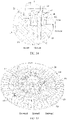
FIG. 2 is a schematic view of a rear structure of a stator according to an embodiment of the present disclosure; -
FIG. 3 is an enlarged view of a structure A inFIG. 2 ; -
FIG. 4 is a cross-sectional view taken along line B-B inFIG. 2 ; -
FIG. 5 is an enlarged view of a structure C inFIG. 4 ; -
FIG. 6 is a schematic view of a stator according to an embodiment of the present disclosure from one view; -
FIG. 7 is an enlarged view of a structure D inFIG. 6 ; -
FIG. 8 is a cross-sectional view taken along line E-E inFIG. 6 ; -
FIG. 9 is an enlarged view of a structure F inFIG. 8 ; -
FIG. 10 is a schematic structural view of a stator body according to an embodiment of the present disclosure; -
FIG. 11 is a partial schematic structural view of a laundry treatment device according to an embodiment of the present disclosure; -
FIG. 12 is a schematic view of a laundry treatment device according to an embodiment of the present disclosure from one view; -
FIG. 13 is a cross-sectional view taken along line G-G inFIG. 12 ; -
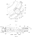
FIG. 14 is an enlarged view of structure H inFIG. 13 ; -
FIG. 15 is a schematic view of an assembled structural of an outer tub and a bearing seat according to an embodiment of the present disclosure; and -
FIG. 16 is an enlarged view of a structure I inFIG. 15 . -
-
laundry treatment device 100,stator 300, -
outer tub 10, mountingseat 11, mountinghole 12, third reinforcingrib 131, fourth reinforcingrib 132,support base 14,support platform 15, annular reinforcingrib 16, - bearing
seat 20,positioning portion 21, -
stator body 30,annular frame 31,stator tooth 32, first positioningmember 33, - injection molded
body 40,central hole 401,connection hole 402, fool-proofingportion 403, wrappingportion 41, mountingportion 42, firstplanar segment 421,inclined segment 422, secondplanar segment 423,connection post 43,support structure 44,annular support column 4401, opening 441,connection rib 45,annular rib 46, first reinforcingrib 47, second reinforcingrib 48,annular positioning flange 49, - fixing
sleeve 50. - The embodiments of the present disclosure will be described in detail below with reference to examples thereof as illustrated in the accompanying drawings, throughout which same or similar elements, or elements having same or similar functions, are denoted by same or similar reference signs. The embodiments described below with reference to the drawings are illustrative only, and are intended to explain, rather than limiting, the present disclosure.
- In the description of the present disclosure, it should be understood that the orientation or position relationship indicated by the terms "center", "longitudinal", "transverse", "length", "width", "thickness", "upper", "lower", "front", "rear", "left", "right", "vertical", "horizontal", "top", "bottom", "inner", "outer", "clockwise", "counterclockwise", "axial", "radial", "circumferential", etc., is based on the orientation or position relationship shown in the drawings, and is only for the convenience of describing the present disclosure and simplifying the description, rather than indicating or implying that the associated device or element must have a specific orientation, or be constructed and operated in a specific orientation, and therefore cannot be understood as a limitation of the present disclosure. In addition, the features associated with "first" and "second" may explicitly or implicitly include at least one of the features. In the description of the present disclosure, "a plurality of' means at least two, unless otherwise defined.
- In the present disclosure, it should be noted that, unless otherwise clearly specified and limited, terms such as "installed", "mounted", "connected", "coupled" and the like should be understood in a broad sense. For example, it may be a fixed connection or a detachable connection or connection as one piece; mechanical connection or electrical connection; direct connection or indirect connection through an intermediate; internal communication of two components, unless otherwise clearly limited. For those of ordinary skill in the art, the specific meaning of the above-mentioned terms in the present disclosure can be understood according to specific circumstances.
- A
stator 300 according to an embodiment of the present disclosure will be described below with reference toFIG. 1 to FIG. 16 . - The following description is made by taking mounting the
stator 30 on a drum washing machine as an example. That is, a bottom of anouter tub 10 of the drum washing machine is used as a base, and a bearing seat inserted into the bottom of theouter tub 10 is used as a support member. It should be noted that thestator 30 of the present disclosure may also be mounted on other devices such as a dryer, a pulsator washing machine, or other devices that need to be driven by a direct drive motor. - As illustrated in
FIG. 1 to FIG. 16 , according to an embodiment of the present disclosure, thestator 300 is adapted to be mounted on theouter tub 10, and includes a mountingportion 42. The mountingportion 42 has a plurality of connection posts 43 provided thereon. Each of the plurality of connection posts 43 has aconnection hole 402 formed therein. Thestator 300 can be fixed to a mountingseat 11 at the bottom of theouter tub 10 by a connector passing through theconnection hole 402. - Here, each of the plurality of connection posts 43 has a
support structure 44 provided thereon and in a direction towards an interior of the stator. One possible scenario is that thesupport structure 44 is closer to the interior of the stator than theconnection hole 402. By providing thesupport structure 44 on theconnection post 43, a structural strength of the connection post can be enhanced. In addition, when theconnection hole 402 is connected to the bottom of theouter tub 10, thesupport structure 44 can share an impact force exerted on the connection post to prevent damages to the mountingseat 11 of theouter tub 10 made of a plastic material. - A bearing
seat 20 is inserted into the bottom of theouter tub 10. Thesupport structure 44 and the bearingseat 20 at least partially overlap with each other in a fixing direction of the connector. The term "overlap" herein may mean that a projection of thesupport structure 44 in a direction perpendicular to a fixing direction of the bearingseat 20 at least partially overlaps with a projection of the bearingseat 20 in this direction. In an embodiment, for example, when the bearingseat 20 is fixed on theouter tub 10 in an upward-downward direction, thesupport structure 44 may be located above or below the bearingseat 20. Thesupport structure 44 may be supported directly or indirectly on the bearingseat 20 during mounting of the connector to disperse and transfer a part of the impact force generated during the mounting of the connector to the bearingseat 20. That is, a part of thesupport structure 44 may be supported directly on a part of the bearingseat 20, or a layer of plastic having a small thickness may be interposed between the part of thesupport structure 44 and the bearingseat 20. In this case, the impact force received by thesupport structure 44 is still borne by the bearingseat 20 to mitigate the impact force received by the mountingseat 11 and avoid damages to the mountingseat 11. - With the
stator 300 according to embodiments of the present disclosure, by arranging thesupport structure 44 and the bearingseat 20 to partially overlap with each other, the impact force to which thesupport structure 44 is subjected during the mounting of the connector may be transferred to the bearingseat 20. The bearingseat 20 can share the impact force to further avoid a deformation of the mountingseat 11 due to the impact force. That is, when the connector, e.g., a screw, is tightened, the mountingseat 11 and the bearingseat 20 share a force acting on the mountingseat 11 by theconnection post 43. Such a manner can improve stability of the overall structure during mounting of the stator. - In some embodiments, the bearing
seat 20 is partially located below thesupport structure 44 supported on the mountingseat 11 of theouter tub 10. Thesupport structure 44 at least partially overlaps with the bearingseat 20. The mountingportion 42 has acentral hole 401 formed in a middle part thereof. A part of the bearingseat 20 protrudes from theouter tub 10 to form apositioning portion 21. The positioningportion 21 is engaged with thecentral hole 401. In this manner, a positioning can be provided during the mounting of the stator. - In some examples, during mounting and fixing of the
stator 300, theconnection post 43 is abutted against and engaged with an end surface engaged with the mountingseat 11, and an upper end surface of the supportingstructure 44 is flush with an upper end surface of theconnection post 43 to further ensure the mounting stability of thestator 300. When theconnection hole 402 is connected to theouter tub 10 by the connector, the upper end surface of thesupport structure 44 and the mountingseat 11 are abutted against and engaged with each other, which can increase a contact area between the upper end surface of thesupport structure 44 and the mountingseat 11 to prevent an outer surface of the bottom of theouter tub 10 from being damage, so that thesupport structure 44 can be abutted against and engaged with the mountingseat 11, thereby ensuring the mounting stability of thestator 300. Also, thesupport structure 44 can disperse and transfer the impact force generated during the mounting to the support member (e.g., the bearingseat 20 illustrated inFIG. 14 ) to avoid damages to a mountinghole 12 on theouter tub 10. - In some examples, a plurality of
support structures 44 is provided and connected to the plurality of connection posts 43 in a one-to-one correspondence. That is, each of the plurality of connection posts 43 has thesupport structure 44 to ensure a same structure at eachconnection post 43. The plurality ofsupport structures 44 is equidistant from an edge of thecentral hole 401 in a radial direction of an imaginary circle to form an outer side surface of thecentral hole 401 into a uniform structure, which in turn avoids differences in accuracy of a circumferential positioning surface of the stator due to plastic contraction. - In some examples, the
support structure 44 has at least oneopening 441 extending in a height direction thereof. Further, theopening 441 may penetrate thesupport structure 44 in the height direction thereof. That is, thesupport structure 44 is formed into a hollow structure. Therefore, thesupport structure 44 can act as a cushion for the connector when the connector passes through theconnection hole 402 and the mountinghole 12 on theouter tub 10 to avoid damages to the mountinghole 12 on theouter tub 10 and to improve the stability of the overall structure. - In some examples, the
support structure 44 is formed as anannular support column 4401 extending in an axial direction of theconnection post 43. Anopening 441 extending in an axial direction of theannular support column 4401 is disposed in theannular support column 4401. Theannular support column 4401 can act as a cushion when theconnection post 43 is engaged with theouter tub 10 to avoid damages to the mountinghole 12 on theouter tub 10 and to improve the stability of the overall structure. - In some examples, the
connection post 43 has at least twoannular support columns 4401 provided thereon. The at least twoannular support columns 4401 are arranged in a circumferential direction of theconnection post 43 and connected to each other to improve the structural strength of theconnection post 43. Also, a cushioning effect can be enhanced when theconnection post 43 is engaged with theouter tub 10 to further avoid damages to the mountinghole 12 on theouter tub 10 and improve the stability of the overall structure. - As illustrated in
FIG. 2 , in some examples, thestator 300 also includes a plurality ofconnection ribs 45 formed into a circular arc rib located on a same circumference. Two adjacent connection posts 43 of the plurality of connection posts 45 are connected to each other by theconnection rib 45. Therefore, a correlation among the plurality of connection posts 43 can be increased, and a structural strength of each of the plurality of connection posts 43 can be enhanced, thereby ensuring a structural stability of thestator 300 while further ensuring stability and reliability of an engagement between each of the plurality ofconnection post 43 and theouter tub 10. - As illustrated in
FIG. 2 , in some examples, thestator 300 also includes anannular rib 46 located on an outer side of the plurality of connection posts 43 and connected to the plurality of connection posts 43. In this manner, the structural strength of the connection posts 43 can be further enhanced. Also, a structural strength of an injection moldedbody 40 on an outer side of theconnection post 43 can be enhanced to prevent the mounting of thestator 300 from being affected by a structural deformation when the connector passes through theconnection hole 402 and the mountinghole 12, and thus the stability of the overall structure can be improved. - In some examples, a side, facing away from the stator, of each of the plurality of connection posts 43 is connected to the
annular rib 46 by a first reinforcingrib 47. That is, the first reinforcingrib 47 has on end connected to theconnection post 43 and another end connected to theannular rib 46. One or more first reinforcingribs 47 may be provided. Such a manner not only enhances a structural strength between theconnection post 43 and theannular rib 46, but also increases the correlation among the plurality of connection posts 43, thereby improving the stability and reliability of the engagement between each of the plurality of connection posts 43 and theouter tub 10. - According to an embodiment of the present disclosure, the
stator 300 is formed by an injection molding process. Thestator 300 includes astator body 30 and an injection moldedbody 40 adapted to be wrapped around thestator body 30. The injection moldedbody 40 includes a wrappingportion 41 wrapped around thestator body 30 and a mountingportion 42 disposed on an inside of the wrappingportion 41. - The
central hole 401 and theconnection hole 402 are defined on the mountingportion 42. Thecentral hole 401 is located in a middle part of the mountingportion 42. In this case, when thestator 300 is mounted to alaundry treatment device 100, thecentral hole 401 can be engaged with thepositioning portion 21 of the bearingseat 20 to provide a quick positioning for the mounting of thestator 300, thereby improving convenience of the mounting of thestator 300. - A plurality of connection holes 402 is arranged at intervals in a circumferential direction of the imaginary circle. The
central hole 401 may be configured for the positioning of thestator 300. In an embodiment, for example, during the mounting of thestator 300, an outer side of the bearingseat 20 may be engaged with thecentral hole 401 to position thestator 300. Each of the plurality of connection holes 402 may be configured to fix thestator 300. In an embodiment, for example, during the mounting of thestator 300, theconnection hole 402 may be fixedly connected to theouter tub 10 of thelaundry treatment device 100 to allow thestator 300 to be fixedly connected to theouter tub 10. Of course, when thestator 300 is mounted on another device, thecentral hole 401 is in position-fit with the bearingseat 20, and theconnection hole 402 is fixedly connected to an outer surface of the other device. That is, a fixed connection of thestator 300 is achieved by theconnection hole 402. - Here, a center of the imaginary circle is coincident with a center of the
central hole 401. That is, a circle where theconnection hole 402 is located is concentric with a circle defined by thecentral hole 40. Thecentral hole 401 can be precisely engaged with the bearingseat 20 during the fixed mounting of thestator 300. That is, a coaxiality between thestator 300 and the bearingseat 20 can be ensured, which in turn enables a rotation shaft on thestator 300 to be precisely engaged with a bearing, thereby ensuring the reliability and stability of the overall structure. - In the radial direction of the imaginary circle, a distance between the edge of the
central hole 401 and the imaginary circle is constant. That is, in the radial direction of the imaginary circle, each of the plurality of connection holes 402 has a same distance from the hole edge of thecentral hole 401. An outer side surface of thecentral hole 401 is formed into a platform having a uniform thickness. During the injection molding of thestator 300, thecentral hole 401 may contract uniformly when the injection moldedbody 40 expands and contracts, which ensures a roundness of thecentral hole 401. Therefore, thecentral hole 401 can be precisely engaged with the bearingseat 20 to ensure an accuracy of a positioning surface of thestator 300. - With the
stator 300 according to the embodiments of the present disclosure, by wrapping thestator body 30 with the injection moldedbody 40, thestator 300 has a simple structure. In addition, the mounting steps are reduced, and the stability of the overall structure can be ensured. Thecentral hole 401 is capable of positioning thestator 300, and theconnection hole 402 is capable of fixing thestator 300. Therefore, the mounting and fixing of thestator 300 can be realized. Since the distance between the imaginary circle where the plurality of connection holes 402 is located and the edge of thecentral hole 401 is constant, an outer side of thecentral hole 401 is formed into a flat surface having a uniform wall thickness, which in turn enables the injection moldedbody 40 to contract uniformly during the injection molding to ensure the roundness of thecentral hole 401. Therefore, the accuracy of the positioning surface of thestator 300 can be ensured to facilitate the mounting and fixing of the stator. - In some examples, the mounting
portion 42 includes a firstplanar segment 421, aninclined segment 422, and a secondplanar segment 423 that are connected to each other sequentially from an outside to an inside in the radial direction of thecentral hole 401. Here, the secondplanar segment 423 has thecentral hole 401 defined in a middle part thereof. Theconnection hole 402 is located at a connection between the firstplanar segment 421 and theinclined segment 422. Theinclined segment 422 gradually extends upwards from the outside to the inside. The mountingportion 42 presents a predetermined height difference. A hole wall of thecentral hole 401 may be abutted against and engaged with an outer side wall of an annular protruding ring (e.g., the positioningportion 21 illustrated inFIG. 16 ) protruding from a surface of the bottom of the outer tub by a predetermined height, and theconnection hole 402 may be abutted against and engaged with an end surface of a mounting protruding post (e.g., the mountingseat 11 illustrated inFIG. 16 ) at the bottom of the outer tub, thereby realizing the mounting of thestator 300. Such a structure can enhance a fixing effect of thestator 300 and improve the connection stability of thestator 300. - According to an embodiment of the present disclosure, the mounting
portion 42 has anannular positioning flange 49 provided thereon, and thecentral hole 401 is defined by theannular positioning flange 49. An inner wall surface of theannular positioning flange 49 may be abutted against and engaged with an outer wall surface of the bearingseat 20 during the mounting of thestator 300. By providing theannular positioning flange 49, it is possible to enlarge an engagement contact area between thecentral hole 401 and the bearingseat 20 to further improve positioning performance. - According to an embodiment of the present disclosure, the
stator 300 also includes a fixingsleeve 50 arranged in theconnection hole 402 and tightly engaged with a wall of theconnection hole 402. In an embodiment, the fixingsleeve 50 may be a steel sleeve inserted into and tightly engaged with theconnection post 43. Since the steel sleeve has a high structural strength, the structural strength of theconnection post 43 can be improved to avoid a deformation of theconnection post 43 during an arrangement of the connector. - As illustrated in
FIG. 10 , according to an embodiment of the present disclosure, thestator body 30 includes anannular frame 31 and a plurality ofstator teeth 32 arranged at intervals in a circumferential direction of theannular frame 31. Here, thestator body 30 is a silicon steel sheet, and the wrappingportion 41 is wrapped around theannular frame 31 and thestator teeth 32. Of course, a part of the plurality ofstator teeth 32 may be exposed by means of a predetermined design during the injection molding. In an embodiment, for example, the wrappingportion 41 is not wrapped around an entire outer end of thestator teeth 32. - In some examples, the
annular frame 31 of thestator 300 has afirst positioning member 33 provided thereon. An injection mold for thestator 300 has a second positioning member provided thereon. During the injection molding of thestator 300, thefirst positioning member 33 is staggered with the second positioning member to ensure that thestator body 30 can be placed in a correct position in the injection mold to prevent thestator body 30 from being misplaced and damaging the injection mold. - In an embodiment, when the
stator body 30 is placed within the injection mold, an information that thestator body 30 is not mounted in place can be obtained by a user when a position of thefirst positioning member 33 corresponds to a position of the second positioning member and an information that thestator body 30 is mounted in place when the position of thefirst positioning member 33 does not correspond to the position of the second positioning member. Such a manner can prevent the injection mold from being damaged by thestator body 30 during the injection molding of the stator. - Since the injection mold for the
stator 300 has the second positioning member, a fool-proofingportion 403 is formed on the injection moldedbody 40 of thestator 300 at a position corresponding to the second positioning member after the stator is injection molded. - In some examples, the
first positioning member 33 is formed as a positioning protruding rib protrudes from theannular frame 31 and extending in an axial direction of the stator. Further, a plurality of positioning protruding ribs may be provided and arranged at intervals in the circumferential direction of theannular frame 31. The plurality ofstator teeth 32 is arranged on an outer side of theannular frame 31, and the plurality of positioning protruding ribs is arranged on an inner side of theannular frame 31. Each of the plurality of positioning protruding ribs is arranged opposite to a corresponding one of the plurality ofstator teeth 32. However, there is no positioning protruding rib arranged at positions opposite to at least a part of the plurality ofstator teeth 32. Therefore, the positioning protruding rib may be staggered with the second positioning member when thestator body 30 is placed within the injection mold. Here, the second positioning member is formed as a bump, and the fool-proofingportion 403 is formed as a fool-proofing recess in a same shape as the bump. - By forming the
first positioning member 33 as the positioning protruding rib located on the inner side of theannular frame 31, each of the plurality ofstator teeth 32 can be located at a corresponding position in the injection mold when thestator body 30 is placed within the injection mold. When the positioning protruding rib is abutted against the bump, thestator body 30 cannot be placed within the injection mold completely. Therefore, the user can obtain the information that thestator body 30 is not mounted in place. In this case, the positioning protruding rib may be staggered with the bump through rotating thestator body 30 by an angle of onestator tooth 32. Therefore, thestator body 30 may be completely placed within the injection mold, and the user can obtain the information that thestator body 30 is mounted in place. Thestator body 30 would not damage the injection mold during the injection molding, and the injection moldedbody 40 can be injection molded. - According to an embodiment of the present disclosure, a motor includes a rotation shaft, a rotor, and the
stator 300. The rotor is located on an outer side of thestator 300 to form an outer rotor structure. The rotation shaft is connected to the rotor. By employing theabove stator 300, the stability of the overall structure can be enhanced, and it is easier for the motor to be engaged with and mounted to theouter tub 10 on thelaundry treatment device 100. In addition, the overall structure has high structural strength and good stability during assembly. - According to an embodiment of the present disclosure, a
laundry treatment device 100 includes theouter tub 10 and the motor. The bearingseat 20 is embedded in the bottom of theouter tub 10. The motor is mounted on an outer side of the bottom of theouter tub 10. The rotation shaft of the motor is engaged with a bearing on the bearingseat 20, and thestator 300 is fixedly connected to the bottom of theouter tub 10. With the above motor, thestator 300 can be fixedly connected to theouter tub 10 directly, which reduces a size of a structure of the bearingseat 20, and eliminates a need of punching holes in the bearingseat 20. Also, there is no necessary for transition member such as the metallic ring for the connection. In addition, thestator 300 is connected to a plastic member in an engagement manner to reduce fabrication costs. An engagement between the rotation shaft and the bearing on the bearingseat 20 can realize a mounting of the rotation shaft while ensuring a stability of the rotation shaft, which makes it possible for the motor to drive a washing tub inside the outer tub. In addition, the bearingseat 20 can bear a part of the impact force generated during the mounting of the connector to prevent the mountinghole 12 on theouter tub 10 from being damaged. - An embodiment of the
laundry treatment device 100 according to the present disclosure will be described below in combination withFIG. 1 to FIG. 16 . - The
laundry treatment device 100 includes an outer tub and a motor. Theouter tub 10 has asupport base 14 provided on a bottom thereof. A bearingseat 20 is embedded in thesupport base 14, and partially protrudes from thesupport base 14 to form an annular protruding ring. - The
outer tub 10 has a plurality ofsupport platforms 15 provided on a bottom thereof. A mountingseat 11 is disposed on each of a plurality ofsupport platforms 15. The mountingseat 11 is formed as a mounting protruding post protruding from thesupport platform 15. The mounting protruding post has a mountinghole 12 defined thereon. Here, the mounting protruding post extends in an axial direction of theouter tub 10. A plurality of mounting protruding posts is arranged at intervals in a circumferential direction of thesupport base 14. An inner side of each of the plurality of mounting protruding posts is connected to thesupport base 14. For example, a direction facing away from the bottom of theouter tub 10 is defined as an upward direction, an upper surface of each mounting protruding post is lower than an upper surface of the support base 14 (as illustrated inFIG. 16 , for ease of understanding, an outer side direction of the bottom of theouter tub 10 is defined as the upward direction in this embodiment). Therefore, a step is formed at a connection between the mounting protruding post and thesupport base 14. Each of the plurality ofsupport platforms 15 has an annular reinforcingrib 16 formed on at outside thereof. A side wall of each mounting protruding post also has a fourth reinforcingrib 132 and a plurality of third reinforcingribs 131. The fourth reinforcingrib 132 extends in a radial direction of the annular reinforcingrib 16 and connects the side wall of the mounting protruding post to the annular reinforcingrib 16. The plurality of third reinforcingribs 131 is arranged at intervals in a circumferential direction of the mounting protruding post. The fourth reinforcingrib 132 is located between two adjacent third reinforcingribs 131. Each of the plurality of third reinforcingribs 131 is connected to the side wall of the mounting protruding post and thesupport platform 15. In this manner, a connection between the mounting protruding post and the bottom of theouter tub 10 can be enhanced to improve structural strength and stability of the mounting protruding post. - The motor includes a rotation shaft, a rotor, and a
stator 300. Thestator 300 has a plurality of connection posts 43 provided on a side thereof facing towards the bottom of theouter tub 10. Aconnection hole 402 is defined on each of the plurality of connection posts 43. The rotor is located on the outer side of thestator 300 to form an outer rotor structure. The rotation shaft is connected to the rotor and adapted to be engaged with a bearing on a bearingseat 20. - The
stator 300 includes astator body 30 and an injection moldedbody 40. Thestator 300 is molded by the injection molding process with thestator body 30 as an insert. Thestator body 30 is a silicon steel sheet, and the injection moldedbody 40 is a plastic member. - The
stator body 30 includes anannular frame 31, and a plurality ofstator teeth 32. The plurality ofstator teeth 32 is located at an outside of theannular frame 31 and arranged at intervals in a circumferential direction of theannular frame 31. Theannular frame 31 has a plurality offirst positioning members 33 provided on the inner side thereof and formed as positioning protruding ribs each protruding from theannular frame 31. The positioning protruding ribs each extend in the axial direction of the stator. Each positioning protruding rib is arranged opposite to a corresponding one of the plurality ofstator teeth 32. - The injection molded
body 40 includes a wrappingportion 41 wrapped around thestator body 30 and a mountingportion 42 disposed at an inside of the wrappingportion 41. During the injection molding of thestator 300, since an injection mold for thestator 300 has a bump staggered with thefirst positioning member 33, a fool-proofing recess corresponding to the bump is formed on the injection moldedbody 40 after the stator is injection molded. - The mounting
portion 42 includes a firstplanar segment 421, aninclined segment 422, and a secondplanar segment 423. The secondplanar segment 423 has anannular positioning flange 49 provided in a middle part thereof. Acentral hole 401 is defined by theannular positioning flange 49, and is adapted to be engaged with the bearingseat 20 to providing a positioning for the mounting of the stator. - A
connection hole 402 is defined at a connection between the firstplanar segment 421 and theinclined segment 422. A plurality of connection holes 402 is provided and arranged at intervals in a circumferential direction of an imaginary circle. A center of the imaginary circle is coincident with a center of thecentral hole 401. In a radial direction of the imaginary circle, a distance between an edge of thecentral hole 401 and the imaginary circle is constant. Therefore, an outer side surface of thecentral hole 401 is formed into a platform having a uniform thickness. During the injection molding of thestator 300, thecentral hole 401 can contract uniformly when the injection moldedbody 40 expands and contracts, which can ensure a roundness of thecentral hole 401. Therefore, thecentral hole 401 can be precisely engaged with the bearingseat 20 to ensure an accuracy of a positioning surface of thestator 300. - The mounting
portion 42 has a plurality of connection posts 43 protruding from an upper surface thereof. Upper surfaces of the plurality of connection posts 43 are located in a same plane. Each of the plurality of connection posts 43 has aconnection hole 402 defined in a center thereof. Theconnection hole 402 penetrates theconnection post 43. A fixingsleeve 50 is disposed in theconnection hole 402. In an embodiment, the fixingsleeve 50 is a steel sleeve inserted into and tightly engaged with theconnection post 43 to improve the structural strength of theconnection post 43. - Two adjacent connection posts 43 of the plurality of connection posts 43 are connected to each other by the
connection rib 45. A plurality ofconnection ribs 45 is provided and formed as circular arc ribs located in a same circumference. Anannular rib 46 is disposed on an outer side of the plurality of connection posts 43. Each of the plurality of connection posts 43 is connected to theannular rib 46 by two first reinforcingribs 47. An outer side of theannular rib 46 is connected to the wrappingportion 41 by a second reinforcingrib 48. Therefore, a connection between the mountingportion 42 and the wrappingportion 41 can be reinforced, and structural strength and stability of the mountingportion 42 can be improved, thereby avoiding a deformation of the mountingportion 42. - Each of the plurality of connection posts 43 has a
support structure 44 provided on a side thereof facing towards thecentral hole 401. Thesupport structure 44 is formed as anannular support column 4401. Eachconnection post 43 has twoannular support columns 4401 provided thereon. An end surface of each of the twoannular support columns 4401 is flush with an end surface of theconnection post 43. The twoannular support columns 4401 are connected to each other and are arranged in the circumferential direction of theconnection post 43. Theannular support column 4401 has anopening 441 defined therein and extending in an axial direction of theannular support column 4401. The structural strength of theconnection post 43 can be enhanced by theannular support column 4401. In addition, during the mounting of thestator 300, the bearingseat 20 is partially located below thesupport structure 44 in an upward-downward direction. Thesupport structure 44 and the bearingseat 20 partially overlaps with each other in the upward-downward direction. - During the mounting of the
stator 300, first, thestator 300 is sleeved over the annular protruding ring. The wall of the central hole 401 (an inner wall surface of the annular positioning flange 49) is abutted against and engaged with an outer wall surface of the annular protruding ring to position thestator 300. A position of theconnection post 43 corresponds to a position of the mounting protruding post. Eachconnection post 43 is abutted against and engaged with an upper end surface of the mounting protruding post at a position corresponding to theconnection post 43. A position of theconnection hole 402 corresponds to a position of the mountinghole 12. Theconnection post 43 is fixedly connected to the mounting protruding post by a self-tapping bolt. Theannular support column 4401 can act as a cushion when theconnection post 43 is engaged with the mounting protruding post. Meanwhile, the impact force is partially transferred to the bearingseat 20 by theannular support column 4401. In this manner, the bearingseat 20 made of a metal can partially bear the impact force, which prevents the mounting protruding post from being damaged and improves the stability of the overall structure. - Therefore, a contact surface between the
connection post 43 and the mounting protruding post is not flush with a plane where thecentral hole 401 is located. That is, a connection surface of the stator is located at a different height from the positioning surface of the stator. Such a manner is convenient for thestator 300 to be engaged with theouter tub 10 and the bearingseat 20, and can also ensure the positioning to be achieved at different positions of thestator 300, thereby increasing the fixing stability of thestator 300. - Other configurations as well as operations of the
laundry treatment device 100 according to the embodiments of the present disclosure are known to those of ordinary skill in the art, and thus details thereof will be omitted herein. - In the present disclosure, unless expressly stipulated and defined otherwise, the first feature "on", or "under" the second feature may mean that the first feature is in direct contact with the second feature, or the first and second features are in indirect contact through another feature between the first and second features. Moreover, the first feature "above" or "over" the second feature may mean that the first feature is directly above or obliquely above the second feature, or simply mean that the level of the first feature is higher than that of the second feature.
- In the description of this specification, descriptions with reference to the terms "an embodiment", "some embodiments", "illustrative embodiments", "examples", "specific examples", or "some examples" etc. mean that specific features, structure, materials or characteristics described in conjunction with the embodiment or example are included in at least one embodiment or example of the present disclosure. In this specification, the schematic representations of the above terms do not necessarily refer to the same embodiment or example. Moreover, the described specific features, structures, materials or characteristics may be combined in any one or more embodiments or examples in a suitable manner.
- Although embodiments of the present disclosure have been illustrated and described, it is conceivable for those of ordinary skill in the art that various changes, modifications, replacements, and variations can be made to these embodiments without departing from the principles and spirit of the present disclosure. The scope of the present disclosure shall be defined by the claims as appended and their equivalents.
Claims (15)
- A stator, adapted to be mounted on a base body, the stator comprising a mounting portion (42) having a plurality of connection posts (43) provided thereon, wherein:each of the plurality of connection posts (43) has a connection hole (402) defined therein;the stator is fixed on a mounting seat of the base body through a connector penetrating through the connection hole (402), the mounting seat being made of a plastic material;each of the plurality of connection posts (43) comprises a support structure (44) provided thereon; andthe base body has a support member provided thereon, the support structure (44) at least partially overlapping with the support member in a fixing direction of the connector.
- The stator according to claim 1, wherein:the support structure (44) is formed on a side, facing towards an interior of the stator, of a corresponding one of the plurality of connection posts (43);the support member is at least partially located below the support structure (44); andthe support structure (44) at least partially overlaps with the support member in an upward-downward direction.
- The stator according to claim 2, wherein the support structure (44) has an upper end surface flush with an upper end surface of the corresponding one connection post (43), and is directly or indirectly abutted against and engaged with the mounting seat of the base body.
- The stator according to any one of claims 1 to 3, wherein the support structure (44) has at least one opening (441) extending in a height direction thereof.
- The stator according to any one of claims 1 to 3, wherein the support structure (44) has an annular support column (4401) formed thereon and extending in an axial direction of the connection post (43).
- The stator according to claim 5, wherein each of the plurality of connection posts (43) comprises at least two annular support columns (4401) provided thereon, the at least two annular support columns (4401) being arranged in a circumferential direction of the connection post (43) and connected to each other.
- The stator according to any one of claims 1 to 6, further comprising a plurality of connection ribs (45) as circular arc ribs located on a same circumference, wherein two adjacent connection posts (43) of the plurality of connection posts (43) are connected to each other by a corresponding one of the plurality of connection ribs (45).
- The stator according to any one of claims 1 to 7, further comprising an annular rib (46) located at an outside of the plurality of connection posts (43) and connected to the plurality of connection posts (43).
- The stator according to claim 8, wherein a side, facing away from an interior of the stator, of each of the plurality of connection posts (43) is connected to the annular rib (46) by at least one first reinforcing rib (47).
- The stator according to any one of claims 1 to 9, wherein:the mounting portion (42) has a central hole (401) defined in a middle part thereof; andthe support member (44) has a part protruding from the base body, the central hole (401) having an edge at least partially in position-fit with the part of the support member (44) protruding from the base body.
- The stator according to claim 10, wherein the mounting portion (42) has an annular positioning flange (49) provided thereon, the central hole (401) being defined by the annular positioning flange (49).
- The stator according to any one of claims 1 to 11, further comprising a fixing sleeve (50) disposed in the connection hole (402) and tightly engaged with a wall of the connection hole (402).
- The stator according to any one of claims 1 to 12, further comprising:a first positioning member (33) adapted to be staggered with a second positioning member of an injection mold for the stator during injection molding of the stator; anda fool-proofing portion (403) disposed on the stator at a position corresponding to the second positioning member.
- A motor, comprising:a rotation shaft;a rotor; andthe stator according to any one of claims 1 to 13.
- A laundry treatment device (100), comprising:an outer tub (10) having a bearing seat (20) embedded in a bottom thereof; andthe motor according to claim 14, wherein:the bottom of the outer tub is formed as the base body;the bearing seat (20) is formed as the support member;the rotation shaft is engaged with a bearing on the bearing seat (20); andthe stator (300) is fixedly connected to the bottom of the outer tub (10).
Applications Claiming Priority (2)
| Application Number | Priority Date | Filing Date | Title |
|---|---|---|---|
| CN202010387881.2A CN111534975B (en) | 2020-05-09 | 2020-05-09 | Stator, motor and clothes treatment equipment |
| PCT/CN2020/100172 WO2021227222A1 (en) | 2020-05-09 | 2020-07-03 | Stator, motor, and laundry treatment device |
Publications (3)
| Publication Number | Publication Date |
|---|---|
| EP4098790A1 true EP4098790A1 (en) | 2022-12-07 |
| EP4098790A4 EP4098790A4 (en) | 2023-07-26 |
| EP4098790B1 EP4098790B1 (en) | 2026-01-21 |
Family
ID=71973618
Family Applications (1)
| Application Number | Title | Priority Date | Filing Date |
|---|---|---|---|
| EP20935675.7A Active EP4098790B1 (en) | 2020-05-09 | 2020-07-03 | Stator, motor, and laundry treatment device |
Country Status (3)
| Country | Link |
|---|---|
| EP (1) | EP4098790B1 (en) |
| CN (1) | CN111534975B (en) |
| WO (1) | WO2021227222A1 (en) |
Family Cites Families (11)
| Publication number | Priority date | Publication date | Assignee | Title |
|---|---|---|---|---|
| JP4119661B2 (en) * | 2002-03-25 | 2008-07-16 | 草津電機株式会社 | Electric motor stator and method of manufacturing the same |
| KR100564442B1 (en) * | 2003-12-10 | 2006-03-29 | 엘지전자 주식회사 | Top Loading Drum Washing Machine |
| KR101022222B1 (en) * | 2004-11-17 | 2011-03-17 | 삼성전자주식회사 | washer |
| WO2007132955A1 (en) * | 2006-05-12 | 2007-11-22 | Lg Electronics Inc. | A tub for a washing machine with a bearing housing inserted therein |
| JP4044601B1 (en) * | 2007-02-14 | 2008-02-06 | 松下電器産業株式会社 | Drum washing machine |
| CN102315729B (en) * | 2011-09-14 | 2013-09-18 | 卧龙电气集团股份有限公司 | Motor stator assembling apparatus and assembling method |
| KR20130091019A (en) * | 2012-02-07 | 2013-08-16 | 삼성전자주식회사 | Motor and washing machine having the same |
| US8950221B2 (en) * | 2012-04-03 | 2015-02-10 | General Electric Company | Motor assembly for washing machine |
| CN105490463B (en) * | 2015-12-18 | 2018-07-13 | 惠而浦(中国)股份有限公司 | Magneto mounting structure and installation method |
| CN208738933U (en) * | 2018-05-02 | 2019-04-12 | 卧龙电气集团股份有限公司 | A kind of motor's for washing machine |
| CN210287841U (en) * | 2019-06-24 | 2020-04-10 | 无锡小天鹅电器有限公司 | Clothes treating device |
-
2020
- 2020-05-09 CN CN202010387881.2A patent/CN111534975B/en active Active
- 2020-07-03 EP EP20935675.7A patent/EP4098790B1/en active Active
- 2020-07-03 WO PCT/CN2020/100172 patent/WO2021227222A1/en not_active Ceased
Also Published As
| Publication number | Publication date |
|---|---|
| CN111534975A (en) | 2020-08-14 |
| BR112022022691A2 (en) | 2023-01-31 |
| CN111534975B (en) | 2022-08-02 |
| EP4098790B1 (en) | 2026-01-21 |
| WO2021227222A1 (en) | 2021-11-18 |
| EP4098790A4 (en) | 2023-07-26 |
Similar Documents
| Publication | Publication Date | Title |
|---|---|---|
| US7615895B2 (en) | Outer rotor type motor for drum type washing machine and method for fabricating the same | |
| US7342344B2 (en) | Stator of outer rotor type motor for drum type washing machine | |
| US7562542B2 (en) | Drum type washer | |
| US6681602B2 (en) | Washing tub for a washing machine | |
| US8276408B2 (en) | Tub having structurally strengthened rear wall and washing machine with the same therein | |
| US20050194859A1 (en) | Stator of outer rotor type motor for drum type washing machine | |
| CN1638233A (en) | Motor for washing machine | |
| CN1905315A (en) | Axial air-gap motor | |
| US20200212739A1 (en) | Rotor and motor | |
| EP4098790B1 (en) | Stator, motor, and laundry treatment device | |
| US20150061420A1 (en) | Motor | |
| EP1978260A1 (en) | Centrifugal drainage pump | |
| CN212611495U (en) | Clothes treating apparatus | |
| EP2332673B1 (en) | Bearing housing of washing machine | |
| US20060059957A1 (en) | Washing machine | |
| KR102657432B1 (en) | motors and washing machines | |
| CN211239542U (en) | Fixed structure of motor stator and washing machine | |
| BR112022022691B1 (en) | STATOR, MOTOR, AND LAUNDRY TREATMENT DEVICE | |
| CN222294479U (en) | A reinforcement structure of a washing tub and a washing machine having the reinforcement structure | |
| KR101154983B1 (en) | Structure of driving unit of drum-type washing machine | |
| CN219568410U (en) | Base assembly for clothes treatment equipment and clothes treatment equipment with base assembly | |
| CN205775381U (en) | For the washing barrels component of washing machine and the washing machine with it | |
| KR20200029867A (en) | Motor | |
| CN110219138A (en) | A kind of washing machine axle sleeve | |
| CN212231185U (en) | Motor iron core fixing structure |
Legal Events
| Date | Code | Title | Description |
|---|---|---|---|
| STAA | Information on the status of an ep patent application or granted ep patent |
Free format text: STATUS: THE INTERNATIONAL PUBLICATION HAS BEEN MADE |
|
| PUAI | Public reference made under article 153(3) epc to a published international application that has entered the european phase |
Free format text: ORIGINAL CODE: 0009012 |
|
| STAA | Information on the status of an ep patent application or granted ep patent |
Free format text: STATUS: REQUEST FOR EXAMINATION WAS MADE |
|
| 17P | Request for examination filed |
Effective date: 20220901 |
|
| AK | Designated contracting states |
Kind code of ref document: A1 Designated state(s): AL AT BE BG CH CY CZ DE DK EE ES FI FR GB GR HR HU IE IS IT LI LT LU LV MC MK MT NL NO PL PT RO RS SE SI SK SM TR |
|
| A4 | Supplementary search report drawn up and despatched |
Effective date: 20230623 |
|
| RIC1 | Information provided on ipc code assigned before grant |
Ipc: H02K 7/14 20060101ALI20230619BHEP Ipc: H02K 1/18 20060101ALI20230619BHEP Ipc: D06F 37/30 20200101AFI20230619BHEP |
|
| DAV | Request for validation of the european patent (deleted) | ||
| DAX | Request for extension of the european patent (deleted) | ||
| GRAP | Despatch of communication of intention to grant a patent |
Free format text: ORIGINAL CODE: EPIDOSNIGR1 |
|
| STAA | Information on the status of an ep patent application or granted ep patent |
Free format text: STATUS: GRANT OF PATENT IS INTENDED |
|
| INTG | Intention to grant announced |
Effective date: 20251014 |
|
| GRAS | Grant fee paid |
Free format text: ORIGINAL CODE: EPIDOSNIGR3 |
|
| GRAA | (expected) grant |
Free format text: ORIGINAL CODE: 0009210 |
|
| STAA | Information on the status of an ep patent application or granted ep patent |
Free format text: STATUS: THE PATENT HAS BEEN GRANTED |
|
| AK | Designated contracting states |
Kind code of ref document: B1 Designated state(s): AL AT BE BG CH CY CZ DE DK EE ES FI FR GB GR HR HU IE IS IT LI LT LU LV MC MK MT NL NO PL PT RO RS SE SI SK SM TR |
|
| REG | Reference to a national code |
Ref country code: CH Ref legal event code: F10 Free format text: ST27 STATUS EVENT CODE: U-0-0-F10-F00 (AS PROVIDED BY THE NATIONAL OFFICE) Effective date: 20260121 |
|
| REG | Reference to a national code |
Ref country code: DE Ref legal event code: R096 Ref document number: 602020065704 Country of ref document: DE |
|
| REG | Reference to a national code |
Ref country code: IE Ref legal event code: FG4D |
|
| REG | Reference to a national code |
Ref country code: NL Ref legal event code: MP Effective date: 20260121 |
|
| PG25 | Lapsed in a contracting state [announced via postgrant information from national office to epo] |
Ref country code: NL Free format text: LAPSE BECAUSE OF FAILURE TO SUBMIT A TRANSLATION OF THE DESCRIPTION OR TO PAY THE FEE WITHIN THE PRESCRIBED TIME-LIMIT Effective date: 20260121 |
|
| REG | Reference to a national code |
Ref country code: AT Ref legal event code: MK05 Ref document number: 1878818 Country of ref document: AT Kind code of ref document: T Effective date: 20260121 |
|
| PG25 | Lapsed in a contracting state [announced via postgrant information from national office to epo] |
Ref country code: RS Free format text: LAPSE BECAUSE OF FAILURE TO SUBMIT A TRANSLATION OF THE DESCRIPTION OR TO PAY THE FEE WITHIN THE PRESCRIBED TIME-LIMIT Effective date: 20260421 |
|
| PG25 | Lapsed in a contracting state [announced via postgrant information from national office to epo] |
Ref country code: ES Free format text: LAPSE BECAUSE OF FAILURE TO SUBMIT A TRANSLATION OF THE DESCRIPTION OR TO PAY THE FEE WITHIN THE PRESCRIBED TIME-LIMIT Effective date: 20260121 |
|
| PG25 | Lapsed in a contracting state [announced via postgrant information from national office to epo] |
Ref country code: PL Free format text: LAPSE BECAUSE OF FAILURE TO SUBMIT A TRANSLATION OF THE DESCRIPTION OR TO PAY THE FEE WITHIN THE PRESCRIBED TIME-LIMIT Effective date: 20260121 |
|
| PG25 | Lapsed in a contracting state [announced via postgrant information from national office to epo] |
Ref country code: GR Free format text: LAPSE BECAUSE OF FAILURE TO SUBMIT A TRANSLATION OF THE DESCRIPTION OR TO PAY THE FEE WITHIN THE PRESCRIBED TIME-LIMIT Effective date: 20260422 |
|
| REG | Reference to a national code |
Ref country code: LT Ref legal event code: MG9D |
|
| PG25 | Lapsed in a contracting state [announced via postgrant information from national office to epo] |
Ref country code: LT Free format text: LAPSE BECAUSE OF FAILURE TO SUBMIT A TRANSLATION OF THE DESCRIPTION OR TO PAY THE FEE WITHIN THE PRESCRIBED TIME-LIMIT Effective date: 20260121 |
|
| PG25 | Lapsed in a contracting state [announced via postgrant information from national office to epo] |
Ref country code: NO Free format text: LAPSE BECAUSE OF FAILURE TO SUBMIT A TRANSLATION OF THE DESCRIPTION OR TO PAY THE FEE WITHIN THE PRESCRIBED TIME-LIMIT Effective date: 20260421 |
|
| PG25 | Lapsed in a contracting state [announced via postgrant information from national office to epo] |
Ref country code: SE Free format text: LAPSE BECAUSE OF FAILURE TO SUBMIT A TRANSLATION OF THE DESCRIPTION OR TO PAY THE FEE WITHIN THE PRESCRIBED TIME-LIMIT Effective date: 20260121 Ref country code: FI Free format text: LAPSE BECAUSE OF FAILURE TO SUBMIT A TRANSLATION OF THE DESCRIPTION OR TO PAY THE FEE WITHIN THE PRESCRIBED TIME-LIMIT Effective date: 20260121 Ref country code: AT Free format text: LAPSE BECAUSE OF FAILURE TO SUBMIT A TRANSLATION OF THE DESCRIPTION OR TO PAY THE FEE WITHIN THE PRESCRIBED TIME-LIMIT Effective date: 20260121 |
|
| PG25 | Lapsed in a contracting state [announced via postgrant information from national office to epo] |
Ref country code: HR Free format text: LAPSE BECAUSE OF FAILURE TO SUBMIT A TRANSLATION OF THE DESCRIPTION OR TO PAY THE FEE WITHIN THE PRESCRIBED TIME-LIMIT Effective date: 20260121 |
|
| PG25 | Lapsed in a contracting state [announced via postgrant information from national office to epo] |
Ref country code: IS Free format text: LAPSE BECAUSE OF FAILURE TO SUBMIT A TRANSLATION OF THE DESCRIPTION OR TO PAY THE FEE WITHIN THE PRESCRIBED TIME-LIMIT Effective date: 20260521 Ref country code: PT Free format text: LAPSE BECAUSE OF FAILURE TO SUBMIT A TRANSLATION OF THE DESCRIPTION OR TO PAY THE FEE WITHIN THE PRESCRIBED TIME-LIMIT Effective date: 20260521 |
|
| PG25 | Lapsed in a contracting state [announced via postgrant information from national office to epo] |
Ref country code: LV Free format text: LAPSE BECAUSE OF FAILURE TO SUBMIT A TRANSLATION OF THE DESCRIPTION OR TO PAY THE FEE WITHIN THE PRESCRIBED TIME-LIMIT Effective date: 20260121 |
|
| PG25 | Lapsed in a contracting state [announced via postgrant information from national office to epo] |
Ref country code: BG Free format text: LAPSE BECAUSE OF FAILURE TO SUBMIT A TRANSLATION OF THE DESCRIPTION OR TO PAY THE FEE WITHIN THE PRESCRIBED TIME-LIMIT Effective date: 20260121 |