EP4098606A1 - Electromechanical microsystem - Google Patents
Electromechanical microsystem Download PDFInfo
- Publication number
- EP4098606A1 EP4098606A1 EP22175727.1A EP22175727A EP4098606A1 EP 4098606 A1 EP4098606 A1 EP 4098606A1 EP 22175727 A EP22175727 A EP 22175727A EP 4098606 A1 EP4098606 A1 EP 4098606A1
- Authority
- EP
- European Patent Office
- Prior art keywords
- free zone
- membrane
- electromechanical
- pin
- microsystem
- Prior art date
- Legal status (The legal status is an assumption and is not a legal conclusion. Google has not performed a legal analysis and makes no representation as to the accuracy of the status listed.)
- Granted
Links
- 239000012528 membrane Substances 0.000 claims abstract description 225
- 230000002093 peripheral effect Effects 0.000 claims abstract description 28
- 230000008859 change Effects 0.000 claims abstract description 19
- 230000009471 action Effects 0.000 claims abstract description 9
- 238000006073 displacement reaction Methods 0.000 claims description 28
- 230000003287 optical effect Effects 0.000 claims description 13
- 229910052710 silicon Inorganic materials 0.000 claims description 7
- 239000010703 silicon Substances 0.000 claims description 7
- 238000013459 approach Methods 0.000 claims description 5
- 230000000284 resting effect Effects 0.000 claims description 3
- 238000000926 separation method Methods 0.000 claims description 2
- 239000000463 material Substances 0.000 description 58
- 238000004519 manufacturing process Methods 0.000 description 28
- 238000005530 etching Methods 0.000 description 25
- 125000006850 spacer group Chemical group 0.000 description 20
- 241000920340 Pion Species 0.000 description 18
- XUIMIQQOPSSXEZ-UHFFFAOYSA-N Silicon Chemical compound [Si] XUIMIQQOPSSXEZ-UHFFFAOYSA-N 0.000 description 17
- 238000000151 deposition Methods 0.000 description 16
- 230000008021 deposition Effects 0.000 description 16
- 239000000758 substrate Substances 0.000 description 16
- 238000005240 physical vapour deposition Methods 0.000 description 15
- 238000000623 plasma-assisted chemical vapour deposition Methods 0.000 description 14
- BASFCYQUMIYNBI-UHFFFAOYSA-N platinum Chemical compound [Pt] BASFCYQUMIYNBI-UHFFFAOYSA-N 0.000 description 12
- 239000000126 substance Substances 0.000 description 12
- 230000000670 limiting effect Effects 0.000 description 10
- 238000002161 passivation Methods 0.000 description 10
- 101100505760 Mus musculus Gsap gene Proteins 0.000 description 9
- 230000015572 biosynthetic process Effects 0.000 description 9
- 238000001459 lithography Methods 0.000 description 9
- 238000001020 plasma etching Methods 0.000 description 9
- 230000008901 benefit Effects 0.000 description 8
- 238000010586 diagram Methods 0.000 description 8
- 210000000056 organ Anatomy 0.000 description 8
- 229920000642 polymer Polymers 0.000 description 8
- VYPSYNLAJGMNEJ-UHFFFAOYSA-N Silicium dioxide Chemical compound O=[Si]=O VYPSYNLAJGMNEJ-UHFFFAOYSA-N 0.000 description 6
- 239000012530 fluid Substances 0.000 description 6
- 239000003292 glue Substances 0.000 description 6
- 238000003475 lamination Methods 0.000 description 6
- 238000004377 microelectronic Methods 0.000 description 6
- 229910052814 silicon oxide Inorganic materials 0.000 description 6
- 239000007788 liquid Substances 0.000 description 5
- 239000004205 dimethyl polysiloxane Substances 0.000 description 4
- 235000013870 dimethyl polysiloxane Nutrition 0.000 description 4
- 238000000034 method Methods 0.000 description 4
- CXQXSVUQTKDNFP-UHFFFAOYSA-N octamethyltrisiloxane Chemical compound C[Si](C)(C)O[Si](C)(C)O[Si](C)(C)C CXQXSVUQTKDNFP-UHFFFAOYSA-N 0.000 description 4
- 238000004987 plasma desorption mass spectroscopy Methods 0.000 description 4
- 229910052697 platinum Inorganic materials 0.000 description 4
- 229920000435 poly(dimethylsiloxane) Polymers 0.000 description 4
- 239000003566 sealing material Substances 0.000 description 4
- 101100536354 Drosophila melanogaster tant gene Proteins 0.000 description 3
- 229910052581 Si3N4 Inorganic materials 0.000 description 3
- 238000005229 chemical vapour deposition Methods 0.000 description 3
- 230000000694 effects Effects 0.000 description 3
- 239000012212 insulator Substances 0.000 description 3
- 230000005291 magnetic effect Effects 0.000 description 3
- 230000036961 partial effect Effects 0.000 description 3
- HQVNEWCFYHHQES-UHFFFAOYSA-N silicon nitride Chemical compound N12[Si]34N5[Si]62N3[Si]51N64 HQVNEWCFYHHQES-UHFFFAOYSA-N 0.000 description 3
- 238000004528 spin coating Methods 0.000 description 3
- PEDCQBHIVMGVHV-UHFFFAOYSA-N Glycerine Chemical compound OCC(O)CO PEDCQBHIVMGVHV-UHFFFAOYSA-N 0.000 description 2
- 229910021417 amorphous silicon Inorganic materials 0.000 description 2
- 230000003042 antagnostic effect Effects 0.000 description 2
- 230000000295 complement effect Effects 0.000 description 2
- PMHQVHHXPFUNSP-UHFFFAOYSA-M copper(1+);methylsulfanylmethane;bromide Chemical compound Br[Cu].CSC PMHQVHHXPFUNSP-UHFFFAOYSA-M 0.000 description 2
- 230000001186 cumulative effect Effects 0.000 description 2
- 238000011161 development Methods 0.000 description 2
- KPUWHANPEXNPJT-UHFFFAOYSA-N disiloxane Chemical class [SiH3]O[SiH3] KPUWHANPEXNPJT-UHFFFAOYSA-N 0.000 description 2
- 238000005265 energy consumption Methods 0.000 description 2
- 239000000835 fiber Substances 0.000 description 2
- PCHJSUWPFVWCPO-UHFFFAOYSA-N gold Chemical compound [Au] PCHJSUWPFVWCPO-UHFFFAOYSA-N 0.000 description 2
- 239000010931 gold Substances 0.000 description 2
- 229910052737 gold Inorganic materials 0.000 description 2
- 238000005304 joining Methods 0.000 description 2
- 238000004518 low pressure chemical vapour deposition Methods 0.000 description 2
- 230000005415 magnetization Effects 0.000 description 2
- 230000007935 neutral effect Effects 0.000 description 2
- 230000008569 process Effects 0.000 description 2
- 238000012545 processing Methods 0.000 description 2
- 238000011084 recovery Methods 0.000 description 2
- 238000007650 screen-printing Methods 0.000 description 2
- 238000003980 solgel method Methods 0.000 description 2
- 238000012546 transfer Methods 0.000 description 2
- 240000008042 Zea mays Species 0.000 description 1
- 230000004913 activation Effects 0.000 description 1
- 239000000853 adhesive Substances 0.000 description 1
- 238000004026 adhesive bonding Methods 0.000 description 1
- 230000001070 adhesive effect Effects 0.000 description 1
- 230000003321 amplification Effects 0.000 description 1
- 238000004458 analytical method Methods 0.000 description 1
- 238000005452 bending Methods 0.000 description 1
- 238000006243 chemical reaction Methods 0.000 description 1
- 239000011248 coating agent Substances 0.000 description 1
- 238000000576 coating method Methods 0.000 description 1
- 230000006835 compression Effects 0.000 description 1
- 238000007906 compression Methods 0.000 description 1
- 238000001514 detection method Methods 0.000 description 1
- 230000005684 electric field Effects 0.000 description 1
- 229940082150 encore Drugs 0.000 description 1
- 229920006332 epoxy adhesive Polymers 0.000 description 1
- 229920006335 epoxy glue Polymers 0.000 description 1
- 239000003302 ferromagnetic material Substances 0.000 description 1
- 235000011187 glycerol Nutrition 0.000 description 1
- 230000005484 gravity Effects 0.000 description 1
- 230000010354 integration Effects 0.000 description 1
- 239000000696 magnetic material Substances 0.000 description 1
- 230000005389 magnetism Effects 0.000 description 1
- 238000005259 measurement Methods 0.000 description 1
- 239000011325 microbead Substances 0.000 description 1
- 238000012986 modification Methods 0.000 description 1
- 230000004048 modification Effects 0.000 description 1
- 238000003199 nucleic acid amplification method Methods 0.000 description 1
- 239000003921 oil Substances 0.000 description 1
- 239000004033 plastic Substances 0.000 description 1
- 230000010287 polarization Effects 0.000 description 1
- 230000002829 reductive effect Effects 0.000 description 1
- 229920005989 resin Polymers 0.000 description 1
- 239000011347 resin Substances 0.000 description 1
- 238000012552 review Methods 0.000 description 1
- 238000007789 sealing Methods 0.000 description 1
- 238000001338 self-assembly Methods 0.000 description 1
- 230000003068 static effect Effects 0.000 description 1
- JPJZHBHNQJPGSG-UHFFFAOYSA-N titanium;zirconium;tetrahydrate Chemical compound O.O.O.O.[Ti].[Zr] JPJZHBHNQJPGSG-UHFFFAOYSA-N 0.000 description 1
- 238000013519 translation Methods 0.000 description 1
Images


Classifications
-
- B—PERFORMING OPERATIONS; TRANSPORTING
- B81—MICROSTRUCTURAL TECHNOLOGY
- B81B—MICROSTRUCTURAL DEVICES OR SYSTEMS, e.g. MICROMECHANICAL DEVICES
- B81B3/00—Devices comprising flexible or deformable elements, e.g. comprising elastic tongues or membranes
- B81B3/0018—Structures acting upon the moving or flexible element for transforming energy into mechanical movement or vice versa, i.e. actuators, sensors, generators
- B81B3/0027—Structures for transforming mechanical energy, e.g. potential energy of a spring into translation, sound into translation
-
- B—PERFORMING OPERATIONS; TRANSPORTING
- B81—MICROSTRUCTURAL TECHNOLOGY
- B81C—PROCESSES OR APPARATUS SPECIALLY ADAPTED FOR THE MANUFACTURE OR TREATMENT OF MICROSTRUCTURAL DEVICES OR SYSTEMS
- B81C1/00—Manufacture or treatment of devices or systems in or on a substrate
- B81C1/00015—Manufacture or treatment of devices or systems in or on a substrate for manufacturing microsystems
- B81C1/00134—Manufacture or treatment of devices or systems in or on a substrate for manufacturing microsystems comprising flexible or deformable structures
- B81C1/00158—Diaphragms, membranes
-
- B—PERFORMING OPERATIONS; TRANSPORTING
- B81—MICROSTRUCTURAL TECHNOLOGY
- B81B—MICROSTRUCTURAL DEVICES OR SYSTEMS, e.g. MICROMECHANICAL DEVICES
- B81B3/00—Devices comprising flexible or deformable elements, e.g. comprising elastic tongues or membranes
- B81B3/0018—Structures acting upon the moving or flexible element for transforming energy into mechanical movement or vice versa, i.e. actuators, sensors, generators
- B81B3/0021—Transducers for transforming electrical into mechanical energy or vice versa
-
- B—PERFORMING OPERATIONS; TRANSPORTING
- B81—MICROSTRUCTURAL TECHNOLOGY
- B81B—MICROSTRUCTURAL DEVICES OR SYSTEMS, e.g. MICROMECHANICAL DEVICES
- B81B2201/00—Specific applications of microelectromechanical systems
- B81B2201/02—Sensors
- B81B2201/0264—Pressure sensors
-
- B—PERFORMING OPERATIONS; TRANSPORTING
- B81—MICROSTRUCTURAL TECHNOLOGY
- B81B—MICROSTRUCTURAL DEVICES OR SYSTEMS, e.g. MICROMECHANICAL DEVICES
- B81B2203/00—Basic microelectromechanical structures
- B81B2203/01—Suspended structures, i.e. structures allowing a movement
- B81B2203/0127—Diaphragms, i.e. structures separating two media that can control the passage from one medium to another; Membranes, i.e. diaphragms with filtering function
-
- B—PERFORMING OPERATIONS; TRANSPORTING
- B81—MICROSTRUCTURAL TECHNOLOGY
- B81B—MICROSTRUCTURAL DEVICES OR SYSTEMS, e.g. MICROMECHANICAL DEVICES
- B81B2203/00—Basic microelectromechanical structures
- B81B2203/01—Suspended structures, i.e. structures allowing a movement
- B81B2203/0181—See-saws
-
- H—ELECTRICITY
- H04—ELECTRIC COMMUNICATION TECHNIQUE
- H04R—LOUDSPEAKERS, MICROPHONES, GRAMOPHONE PICK-UPS OR LIKE ACOUSTIC ELECTROMECHANICAL TRANSDUCERS; DEAF-AID SETS; PUBLIC ADDRESS SYSTEMS
- H04R2201/00—Details of transducers, loudspeakers or microphones covered by H04R1/00 but not provided for in any of its subgroups
- H04R2201/003—Mems transducers or their use
Definitions
- the present invention relates to the field of microelectromechanical systems. For example, it finds a particularly advantageous application in the actuation or displacement of objects, including over relatively long distances. It also finds for application gripping devices which allow the capture or expulsion of small objects. The invention also finds application in the field of detection by contact. It can thus be implemented to produce sensors.
- microsystems that allow this.
- microsystems When these microsystems are actuators or gripping devices, their performance is evaluated in particular on the following parameters: the amplitude of the displacement, the force deployed, the precision of the displacement generated or the precision of the capture or expulsion of 'an object.
- microsystems When these microsystems are sensors, their performance is evaluated in particular on the following parameters: the ability to capture a movement over a large amplitude and the precision of the measurement.
- microsystems are actuators, gripping devices or sensors, it is sought that they offer good performance in terms of size, energy consumption and ability to work at frequency.
- An object of the present invention is to provide a micro-electromechanical system which has improved performance compared to existing solutions, at least for one of the parameters mentioned above, or which has a better compromise with regard to at least two of the parameters mentioned above.
- the mobile part of the electromechanical transducer is configured so that its movement is a function of said change in external pressure, or conversely that its movement induces a change in external pressure.
- Said at least part of the deformable membrane has at least one zone free to deform, preferably elastically, depending on said change in external pressure.
- the free zone has an outer periphery and a peripheral portion which extends from the outer periphery and to a central portion of the free zone.
- the microelectromechanical system proposed makes it possible to obtain an inclination of the pin according to an angle having a high amplitude relative to the deformation of the membrane. It is then possible, even with a micro-electromechanical system of small dimensions, to obtain large deflections.
- the second end of the pin that is to say the end of the pin opposite to its end resting on the membrane, moves along a long stroke.
- the displacement of the second end of the pin can take place over a stroke length which can be expressed in angular form.
- the second end of the pin moves through an angle of at least 45° and preferably between 0° and 90°.
- the microelectromechanical system as introduced above is thus able to move the pin or to pick up a movement imposed on the latter, and this by presenting, in an easily adjustable manner depending on the targeted applications, a sufficient capacity in terms of amplitude. of movement and/or a sufficient capacity in terms of force deployed and/or a capacity to capture the movement, or even capture, of an object and/or a sufficient capacity to work in frequency and/or a size compatible with the applications targeted, and/or reduced energy consumption.
- Another aspect of the invention relates to an opto-electromechanical system or microsystem comprising at least one electromechanical microsystem as introduced above and at least one optical microsystem.
- the optical microsystem comprises at least one mirror, preferably based on silicon.
- the opto-electro-mechanical system is configured so that the movement of the mobile part of the electromechanical transducer causes a displacement, preferably an inclination, of the at least one mirror.
- microelectromechanical system as introduced above, comprising, or even being limited to, ordinary deposition and etching steps in microelectronics.
- the microelectromechanical system can in fact be manufactured by ordinary microelectronics means, which gives its manufacturer all the advantages deriving from the use of these means, including great latitude in terms of dimensioning, adhesion energy between the different deposits, the thickness of the different deposits, the extent of etching, etc.
- the free zone of the membrane extends mainly in a plane (xy), called the plane without deformation or plane at rest, and the perpendicular to the tangent at a given point of the zone free extends in a direction T1 perpendicular to the plane outside the deformation.
- the perpendicular to the tangent at a given point of the peripheral portion of the free zone extends along a direction Ti, inclined with respect to direction T1, by an angle ai (the angle ai being measured in a plane perpendicular to the plane outside the deformation).
- the angle ⁇ increases as one moves away from the central portion and as one approaches the outer periphery of the free zone.
- the microelectromechanical system is configured so that a deformation of the free zone of the membrane leads to an inclination of the pin in a plane perpendicular to a plane (xy) in which an outer face of the membrane mainly extends when the membrane is not deformed.
- the inclination can be measured by an angle ⁇ contained in a plane perpendicular to the xy plane.
- the pin extends mainly in a longitudinal direction.
- the longitudinal direction of the pin is substantially perpendicular to a plane (xy) in which mainly extends an outer face of the membrane when the membrane is not deformed.
- the pin may have a cylindrical shape.
- the pin does not have a cylindrical shape. It may have a curved shape for example.
- the pin has a first end by which it rests on the peripheral portion of the free zone and a second end opposite the first end.
- the microelectromechanical system is configured so that a deformation of the free zone of the membrane causes the first end to tilt in the direction of the central portion of the free zone.
- the pin extends between the first end and the second end mainly in a longitudinal direction.
- the pawn has a curved shape or extends in several different directions.
- the free zone has a central portion extending from a center of the free zone and a peripheral portion arranged around the central portion.
- the peripheral zone is continuous. It has a full outline. Alternatively, it has an open contour.
- the central portion comprises a center of the free zone, the center corresponds for example to the center of gravity of the free zone.
- the free zone forms a disc, an ellipse or a polygon and said center corresponds to the barycenter of the free zone.
- the central portion does not form a disc, an ellipse or a polygon.
- the central portion can at least partially surround the electromechanical transducer.
- the central portion may for example have an elongated shape. This elongated shape can extend along several segments presenting different directions.
- the microelectromechanical system comprises a plurality of pins, each resting on the peripheral portion of the free zone so that a deformation of the free zone of the membrane causes the pins to tilt.
- the pins have a free end, opposite the end by which they bear on the peripheral portion of the free zone, the pins being shaped so that a deformation of the free zone of the membrane selectively causes a bringing together or moving away from their free ends.
- the pawns are shaped so that a deformation of the free zone of the membrane selectively causes the free ends of the pawns to come into contact with or move away from each other.
- the pins are distributed over the peripheral portion so that the bringing together of their free ends makes it possible to grasp between the free ends and/or to retain between the membrane and the pins an object external to the microelectromechanical system. Bringing their free ends together makes it possible to form a cage above the free zone of the membrane.
- This embodiment makes it possible to obtain a particularly reliable and precise gripping device.
- the large angular deflection of the pawns makes it possible to capture and release objects of relatively large sizes compared to the size of the pawns and the size of the microelectromechanical system.
- the object is not fixed to the microelectromechanical system. A fortiori, it is not fixed to the pawns.
- the object is an external organ.
- the pawn or pawns are configured to cooperate with an object forming an external member such that the movement of the movable part of the electromechanical transducer is a function of a displacement of the pin(s) driven by the external member or, conversely, that the movement of the movable part of the electromechanical transducer induces a displacement, in particular an inclination, of the external organ via the pion.
- This embodiment provides a reliable and accurate actuator or sensor.
- the large angular travel of the pins allows movement of the external member over a relatively large stroke compared to the size of the pin(s) and the size of the microelectromechanical system.
- the peg(s) can be configured to cooperate with the external member via a guide secured to the outer member, so as to allow automatic positioning of the external member on the peg(s).
- the pawn(s) can be configured to be able to be secured with the external member by bonding or magnetism, the adhesion energy of the pawn(s) on the free zone of the deformable membrane preferably being greater than that of the pawn or pawns on the external organ.
- An attachment, optionally removable, of the peg(s) and the external member is thus provided which is largely adjustable in terms of retaining force.
- the microelectromechanical system further comprises at least one lateral abutment, preferably supported by said first wall of the cavity, configured to guide the movement of the external member.
- the pin extends from the free zone of the deformable membrane beyond said at least one lateral stop. According to an alternative example, the pin extends from the free zone of the deformable membrane below said lateral stop.
- the pin is fixed on said free zone, preferably in direct contact with said free zone.
- the micro electromechanical system comprises a plurality of electromechanical transducers.
- the electromechanical transducers are separated from each other. Their moving parts are not in contact. Alternatively, they are contiguous.
- an electromechanical transducer surrounds, at least partially, or even entirely, one or more other electromechanical actuators, in particular their moving part. Furthermore, they can be operated independently of each other.
- each electromechanical transducer has a movable part configured so that its movement is a function of said change in external pressure, or conversely that its movement induces a change in external pressure exerted on the deformable medium through one of the walls of the cavity. .
- the microelectromechanical system comprises several electromechanical transducers for a cavity.
- At least some of the electromechanical transducers of said plurality are configured so that, under stress, their moving parts induce deformations of the free zone of the membrane causing the at least one pin to tilt in the same direction.
- electromechanical transducers each make it possible to move the at least one pawn in the same direction and each over an amplitude.
- the total inclination of the pin results from the cumulative displacement of the moving parts of these electromechanical transducers.
- the microelectromechanical system thus has a step-by-step operation; this makes it possible to limit the addressing voltage.
- the electromechanical transducers can be activated simultaneously or successively.
- the displacement amplitude of the pion induced by each electromechanical transducer can be identical or different.
- At least some of the electromechanical transducers of said plurality are configured so that, under stress, their moving parts induce deformations of the free zone of the membrane causing the at least one pin to tilt in two opposite directions.
- At least two of these electromechanical transducers make it possible to move the at least one pin in two opposite directions. These two electromechanical transducers are therefore antagonistic. Thus, at least one of these electromechanical transducers makes it possible to tilt the pin in a first direction and at least one other of these electromechanical transducers makes it possible to tilt the pin in a second direction opposite to the first direction. This makes it possible to further increase the amplitude of the inclination possible for the pawn.
- These two opposing electromechanical transducers can be separated from each other by a non-zero distance.
- one of these electromechanical transducers can surround, preferably entirely, the other electromechanical transducer.
- the same transducer makes it possible to perform these two alternating movements. It is possible for this to use an AlN transducer for example.
- the microelectromechanical system comprises several free zones, separated from each other by a non-zero distance.
- These free zones can be formed by the same membrane. Alternatively, these free zones can be formed by distinct membranes.
- the free zone is free to deform, preferably elastically, depending on said change in external pressure.
- microelectromechanical system as introduced above is preferably free of optical element, such as a lens, in particular with variable focal length.
- the pin is not fixed in the center of the free zone of the deformable membrane. In this way, the movement of the pin is not a translational movement perpendicular to the wall of the cavity which is partly formed by the deformable membrane.
- At least a part of the electromechanical transducer forms a part of the wall of the cavity which is partly formed by the deformable membrane.
- the microelectromechanical system according to this characteristic has a non-through structure, leaving the other walls of the cavity free so as to be able to perform other functions therein or so as to allow them to remain inert, for an increased integration capacity in particular in an opto-electro-mechanical microsystem.
- the electromechanical transducer can extend, directly or indirectly, over the deformable membrane, and preferably around the free zone of the deformable membrane. Furthermore, the electromechanical transducer can take an annular shape, the circular center of which defines the extent of the free zone of the deformable membrane.
- the mobile part of the electromechanical transducer may have a surface at least twice greater, or even at least 5 times greater, and preferably at least ten times greater than a surface of the free zone of the deformable membrane, or even the surface of the free zones. of the deformable membrane.
- the deformable membrane is preferably configured so that its free zone is capable of deforming with an amplitude of at least 50 ⁇ m, or even at least 100 ⁇ m, or even at least 1000 ⁇ m in a direction perpendicular to the plane in which it stretches mainly when at rest. Without tearing and/or without significant wear, the microelectromechanical system thus offers the ability to satisfy many and various applications requiring a large deflection, the latter being defined, where appropriate, by technical field concerned.
- At least a part of the electromechanical transducer forms part of said first wall of the cavity.
- the electromechanical transducer extends directly over the deformable membrane, ie the electromechanical transducer is directly in contact with the deformable membrane.
- the electromechanical transducer extends indirectly over the deformable membrane, ie at least one element or an intermediate layer is placed between the electromechanical transducer and the deformable membrane.
- the electromechanical transducer extends around the free zone of the deformable membrane.
- the electromechanical transducer entirely surrounds the free zone of the deformable membrane, the electromechanical transducer preferably having an annular shape, the circular center of which defines the extent of the free zone of the deformable membrane.
- the microelectromechanical system may further comprise at least one lateral stop configured to guide the movement of the pin or of the external member if it is present.
- the lateral abutment is supported by the wall of the cavity which is partly formed by the deformable membrane.
- said at least one lateral stop extends opposite the cavity.
- the free zone of the deformable membrane is configured to cooperate with the external organ via the pin fixed to said free zone.
- the pin can extend from the free zone of the deformable membrane beyond said at least one lateral stop.
- the pin can extend from the free zone of the deformable membrane below said at least one lateral stop.
- the microelectromechanical system according to one or the other of these two characteristics offers satisfactory adaptability to a wide variety of external components and applications.
- the microelectromechanical system may further comprise a so-called low stop supported by the wall of the cavity opposite the free zone of the deformable membrane, said lower stop extending into the cavity towards the free zone. It has a shape and dimensions configured to limit the deformation of the free zone of the deformable membrane so as to protect the deformable membrane, and more particularly its free zone, in particular from possible tearing, during a transfer or a bonding of the external organ.
- the so-called low abutment is shaped to limit the contact surface between the membrane and the wall of the cavity opposite the free zone of the deformable membrane.
- the bottom abutment is shaped so as to limit the contact surface between the membrane and the wall of the cavity opposite the free zone of the deformable membrane. This prevents the membrane from adhering to this wall.
- the electromechanical transducer may be a piezoelectric transducer, preferably comprising a PZT-based piezoelectric material.
- the electromechanical transducer may be a statically operated transducer.
- the electromechanical transducer can be a transducer with vibratory operation at at least one resonance frequency, said at least one resonance frequency being preferably less than 100 kHz, and even more preferably less than 1 kHz.
- the deformable medium hermetically contained in the cavity may comprise at least one of a fluid and/or a liquid, and microbeads, the fluid preferably having a viscosity of the order of 100 cSt at ambient temperature and pressure.
- the fluid has a compressibility of between 10 -9 and 10 -10 Pa -1 at 20°C, for example of the order of 10 -10 Pa -1 at 20°C, without these values are limiting.
- microelectromechanical system as introduced above may further comprise a plurality of deformable membranes and/or a plurality of free zones per deformable membrane and/or a plurality of electromechanical transducers.
- Said at least one optical microsystem of the opto-electro-mechanical system as introduced above may comprise at least one mirror, also referred to as a micro-mirror, preferably based on silicon.
- the opto-electro-mechanical system is configured so that the movement of the mobile part of the electromechanical transducer causes a movement of the at least one mirror.
- electromechanical microsystem means a system comprising at least one mechanical element and at least one electromechanical transducer made on a micrometric scale with microelectronic means.
- the transducer electromechanical can sense a movement of the mechanical element; the microelectromechanical system then acts as a sensor.
- the mechanical element can be set in motion (actuated) thanks to a force generated by the electromechanical transducer.
- the microelectromechanical system then plays the role of actuator or gripping device.
- the electromechanical transducer can be powered by electrical voltages produced with neighboring electronic circuits.
- a “microsystem” is a system whose external dimensions are less than 1 centimeter (10 -2 meters) and preferably 1 millimeter (10 -3 meters).
- an electromechanical transducer acts as an interface between the mechanical and electrical domains.
- electromechanical transducer means both a piezoelectric transducer and a thermal transducer, the latter acting as an interface between the mechanical and thermal domains.
- An electromechanical transducer may comprise a movable part between a position of equilibrium, without stress, and a position out of equilibrium, under stress. When the transducer is piezoelectric, the stress is of an electrical nature. When the transducer is thermal, the stress is thermal in nature.
- this center is defined geometrically by considering it to be the center of a cavity having an undeformed free zone of the deformable membrane.
- a parameter “substantially equal/greater/less than” a given value is meant that this parameter is equal/greater/less than the given value, to plus or minus 20%, or even 10%, close to this value.
- a parameter “substantially between” two given values means that this parameter is at least equal to the smallest given value, to plus or minus 20%, or even 10%, close to this value, and at most equal to the smallest value. large given value, plus or minus 20%, or even 10%, close to this value.
- the figures 1 and 2 are block diagrams, respectively of a cross-section and top view, of an example of a microelectromechanical system 1 according to the invention.
- the figures 3A and 3B illustrate the micro-electromechanical system of figures 1 and 2 , in use.
- FIG 1 Shown are an electromechanical transducer 11, a deformable membrane 12, and a cavity 13 configured to hermetically contain a deformable medium 14.
- each of these illustrations schematically represents an embodiment of the microelectromechanical system which has a non-through structure. More particularly, in the various modes illustrated, the electromechanical transducer 11 and the deformable membrane 12 are both located on the front face FAV of the microelectromechanical system 1. This type of structure is particularly advantageous insofar as the rear face FAR of the microelectromechanical system 1 can participate only passively, and in particular without becoming deformed, in the function of actuator and/or gripping device and/or sensor of the microelectromechanical system 1.
- the rear face FAR of a microelectromechanical system 1 to non-through structure can in particular constitute a face via which the micro-electromechanical system 1 can easily be mounted on a support and/or can constitute a face via which the micro-electromechanical system can easily be further functionalized.
- the invention is not limited to microelectromechanical systems with a non-through structure.
- the invention also relates to so-called cross-structure electromechanical microsystems 1 in which the electromechanical transducer 11 and the deformable membrane 12 are arranged on walls separate from each other from the cavity 13, whether these walls are adjacent or opposite each other.
- the electromechanical transducer 11 comprises at least one movable part 111.
- the latter is configured to move or be moved between at least two positions.
- a first of these positions is an equilibrium position reached and maintained when the electromechanical transducer 11 is not stressed, whether for example by an electric current supplying it or by a force forcing it out of its equilibrium position. .
- a second position of the movable part 111 of the electromechanical transducer 11 is reached when the electromechanical transducer 11 is stressed, whether for example by an electric current supplying it or by a force forcing it out of its position of equilibrium.
- the electromechanical transducer 11 can be maintained in one or the other of the first and second positions described above, and thus present a binary behavior, or can be moreover maintained in any intermediate position between its position of equilibrium and its position of greatest distance, or greatest deformation, from equilibrium.
- the electromechanical transducer 11 is preferably a piezoelectric transducer.
- Each electromechanical transducer 11 comprises at least one piezoelectric material mechanically coupled to another element, referred to as a support or a beam.
- the term beam in no way limits the shape of this element.
- a piezoelectric material has the property of constraining itself when an electric field is applied to it. By constraining itself, it deforms. Mechanically associated with the support, the piezoelectric material drives the support with it and then moves the latter. The area of the support capable of moving corresponds to the moving part 111. It is this property of movement which is used to form an actuator.
- a piezoelectric material becomes electrically polarized.
- the support is moved, it deforms the piezoelectric material which induces an electric current. It is this property that is used to form a sensor.
- the electromechanical microsystem 1 can function as an actuator and/or as a gripping device and/or as a sensor.
- the electromechanical transducer 11 is even more preferably a piezoelectric transducer comprising a piezoelectric material based on PZT (Lead Titanium-Zirconate).
- the mobile part 111 of the electromechanical transducer 11 is capable, under stress, of moving with a more significant displacement (due to the piezoelectric coefficient d31) than with a large number of other piezoelectric materials.
- the electromechanical transducer 11 can be a piezoelectric transducer (non-ferroelectric) based on a material capable of allowing its mobile part 111 to move in opposite directions relative to its position of equilibrium, for example depending on the polarity of its power supply.
- a material is for example a material based on aluminum nitride (AIN).
- the electromechanical transducer 11 may be or include a thermal transducer.
- the deformable membrane 12 can be based on a polymer, and is preferably based on PDMS.
- the properties of the deformable membrane 12 in particular its thickness, its surface and its shape can be configured to confer on the deformable membrane 12, and more particularly on a zone 121 of this membrane which is free to deform, a stretching capacity expected, in particular depending on the intended application.
- the cavity 13 may have a symmetry of rotation or revolution around a z axis perpendicular to the xy plane, as illustrated in picture 2 .
- the cavity may have, seen from above, a polygonal shape, for example as illustrated in the figures 17A to 17D which will be described in detail later.
- the cavity 13 as illustrated in particular on the figure 1 , 3A and 3B more particularly has walls 131, 132, 133 hermetically containing the deformable medium 14.
- the wall 132 of the cavity 13 constitutes the rear face FAR of the microelectromechanical system 1.
- the wall 131 opposite the wall 132 is formed at least in part by at least a part of the deformable membrane 12.
- the wall 131 is deformable.
- the wall 131 can be referred to as the first wall below. It is located at the front face FAV of the microelectromechanical system 1.
- At least one side wall 133 joins the walls 131 and 132 between them.
- the hermeticity of the cavity 13 requires that the deformable membrane 12 itself be impermeable, or rendered impermeable, in particular at the level of its free zone 121.
- the walls 132, 133 remain fixed when the membrane deforms.
- the deformable medium 14 is itself capable of maintaining a substantially constant volume under the action of a change in external pressure.
- it may be an incompressible or weakly compressible medium, the deformation of which preferably requires little energy. It is for example a liquid.
- any change in external pressure exerted on the deformable medium 14 can be compensated by a deformation, substantially proportional, of the deformable membrane 12, and more particularly of its free zone 121 (operation as an actuator or as a gripping device) and/or by a displacement of the mobile part 111 of the electromechanical transducer 11 ( functioning as a sensor).
- this compensation is more particularly linked to a conversion of the change in external pressure exerted on the deformable medium 14 into a stretching of the deformable membrane 12 or a relaxation of the deformable membrane 12 already stretched.
- the deformable medium 14 is preferably incompressible and that these stresses therefore preferably take place with conservation of the volume of the cavity 13. It is understood that, for the sake of reproducibility of the actuation or capture of movement offered by the microelectromechanical system 1 according to the invention, it is preferable that any deformation of the deformable membrane 12 be elastic, and not plastic, to guarantee the return to the same state of least stretching, or of maximum relaxation, of the deformable membrane 12 each time it is no longer constrained.
- the electromechanical transducer 11 can form part of the first wall 131 of the cavity 13.
- the electromechanical transducer 11 and the deformable membrane 12 are thus placed on the same side of the cavity 13.
- the structures having this characteristic are advantageously not through , as mentioned above.
- the membrane 12 has an internal face 12i configured to be in contact with the deformable medium 14 and an external face 12e.
- the internal face 12i forms a part of the wall 131 of the cavity 13.
- the electromechanical transducer 11, more precisely the mobile part 111 of the latter, has an internal face 11i facing, and preferably in contact with the external face 12e of the membrane 12.
- the electromechanical transducer 11 also has an outer face 11e, opposite to the inner face 11i, and facing the outside of the microelectromechanical system 1.
- the electromechanical microsystem 1 is configured so that the movement of the mobile part 111 of the electromechanical transducer 11 causes a displacement of the membrane 12 and therefore of the wall 131 which encloses the middle 14.
- the electromechanical transducer 11 can advantageously be integral with the deformable membrane 12 at least on a zone 123 located outside the free zone 121, and more particularly substantially adjacent to the free zone 121, so that any movement of the movable part 111 of the electromechanical transducer 11 induces, in particular on this zone 123, a stretching or a relaxation of the deformable membrane 12.
- a zone 123 located outside the free zone 121, and more particularly substantially adjacent to the free zone 121, so that any movement of the movable part 111 of the electromechanical transducer 11 induces, in particular on this zone 123, a stretching or a relaxation of the deformable membrane 12.
- the deformable medium 14 can more particularly comprise at least one of a fluid and/or a liquid.
- the parameters of the liquid will be adapted according to the targeted applications. This ensures that any change in external pressure exerted on the deformable medium 14 induces a substantially proportional deformation of the free zone 121 of the deformable membrane 12.
- the fluid may consist of, or be based on, of a liquid, such as oil, or may consist of, or be based on, a polymer. According to one example, the fluid is based on, or consists of, glycerin.
- the electromechanical transducer 11 When the microelectromechanical system 1 plays the role of actuator or gripping device, the electromechanical transducer 11 is stressed so as to exert a change in external pressure on the deformable medium 14 and thereby induce the deformation of the deformable membrane 12. Conversely, when the microelectromechanical system 1 acts as a sensor, the deformation of the membrane 12 exerts a change in external pressure on the deformable medium 14 which induces a displacement of the mobile part 111 of the electromechanical transducer 11 and consequently generates a electrical signal.
- the microelectromechanical system 1 is such that the free zone 121 of the deformable membrane 12 is configured to cooperate with at least one finger, generally designated pin 122.
- the terms “finger” and “pin” can be interchanged.
- the term “pawn” is not limited to parts of constant section and a fortiori to cylindrical parts.
- the pin 122 bears on an outer face 12e of the free zone 121.
- the deformation of the free zone 121 induces, or is induced by, a movement of the pin 122. It is therefore by the intermediate of the free zone 121 of the deformable membrane 12 that the micro electromechanical system 1 moves the pin 122 or picks up a movement of the pin 122.
- the micro electromechanical system 1 plays the role of actuator or gripping device, the activation of the electromechanical transducer 11 deforms the membrane 12 which moves the pin 122.
- a support or a traction imposed on the pin 122 for example by an external member 2
- a deformation (compression or traction) which moves the electromechanical transducer 11 then ultimately generates a signal which may be a function of this movement.
- the movement of the object or the capture of the movement of the object can be carried out via an external member 2 which cooperates with the pin 122.
- the micro electromechanical system 1 can comprise several pins 122.
- the pins 122 of the same micro electromechanical system 1, even the pins 122 of the same free zone 121, can have different shapes and/or dimensions.
- the pawns can have different heights. This makes it possible, for example, to adapt to the objects that one wishes to move, capture or whose displacement one wishes to capture, or even measure.
- pin 122 is not attached to the center of free zone 121 of deformable membrane 12. Pin 122 is positioned off-center on free zone 121.
- the free zone 121 of the membrane 12 has a central portion 125 and a peripheral portion 126 which extends from the central portion 125 and up to an edge, also designated outer perimeter 129 of the free zone 121.
- the membrane 12 forms a disc.
- the central portion 125 also forms a disc centered on a center 124 of the free zone 121.
- the peripheral portion 126 forms a ring surrounding the central portion 125.
- the outer perimeter 129 is for example defined by a cover 18 which holds the membrane 12.
- the membrane 12 is thus located between the cover 18 and the deformable medium 14.
- This cover 18 extends for example in the xy plane. It has at least one opening which defines the free area 121.
- the cover 18 extends over the entire surface of the cavity 13, in projection on the xy plane, with the exception of an opening defining the free zone 121 of the membrane 12 and another opening 123 in which a part of the electromechanical transducer 11 is housed, and in particular its movable part 111.
- the cover 18 has a zone 127 (illustrated in particular on the figure 1 ) which separates these two openings 121 and 123.
- the pin 122 is configured to bear on the peripheral portion 126 of the free zone 121 so that a deformation of the free zone 121 of the membrane 12 causes a tilt of the pin 122.
- the pin 122 has a first end 122a bearing, directly or indirectly, on the external face 12e of the free zone 121. It also has a second end 122b. According to a non-limiting embodiment, the pin 122 extends, between its first end 122a and its second end 122b, mainly in a single direction, referred to as the longitudinal direction 122c.
- the pin 122 has a cylindrical or tubular shape, of circular, ovoid or polygonal section. When the free zone 121 deforms, its longitudinal direction 122c tilts in a plane perpendicular to the xy plane.
- the pin 122 does not have a cylindrical shape. It may have a curved shape for example. The characteristics and technical advantages mentioned below remain valid if the pin 122 has a curved or other shape.
- the perpendicular to the tangent at a given point of the peripheral portion 126 of the free zone 121 extends along a direction Ti, inclined with respect to the direction T1, by an angle ai.
- the angle ai is measured in a plane perpendicular to the plane outside the deformation xy.
- the angle ai is illustrated in Figure 3A .
- the free zone 121 of the membrane 12 generally has the shape of a portion of a sphere, a dome or a bell from its outer circumference 129.
- the angle ai increases as one s moves away from the central portion 125 and as one approaches the outer perimeter 129.
- the longitudinal direction 122c of the pin 122 extends in the direction T2 perpendicular to the tangent of the membrane at the point where the end 122a of the pin 122 bears against the free zone 121.
- the longitudinal direction 122c of the pin 122 tilts.
- the longitudinal direction 122c of the pin when the membrane 12 is deformed, forms an angle a2 with the direction 122c outside the deformation.
- microelectromechanical system 1 proposed allows a particularly high angular displacement for a given deformation of the free zone 121 of the membrane 12.
- the proposed solution thus makes it possible to considerably amplify the movement of the end 122b of pin 122.
- microelectromechanical system 1 proposed also provides numerous advantages when it acts as a gripping device. These advantages will be described in detail later with reference to the figures 4 to 6E .
- a displacement of the mobile part 111 of the electromechanical transducer 11 in a first direction causes a deformation of the free zone 121 of the membrane 12 in a second direction opposite to the first direction, and induces an inclination of the piece 122 in a first direction.
- the downward movement of the mobile part of the electromechanical transducer 11 causes an upward deformation of the free zone 121 of the membrane 12, and a tilting to the left of the longitudinal direction 122c of the pin 122
- a displacement of the mobile part 111 of the electromechanical transducer 11 upwards causes a deformation of the free zone 121 of the membrane 12 downwards, and induces an inclination of the original direction 122c of the pin 122 towards the right.
- the pin 122 is located at a minimum distance D122 from a point 128 of the outer perimeter 129, such that D122 is less than k times the distance D124 measured between this same point 128 and the center 124 of the free zone 121.
- the point 128 is the point of the outer circumference 129 closest to the pin 122.
- k is less than 0.7, preferably k is less than 0.5 and preferably k is less than 0.3. More generally, the closer the pin 122 is positioned to the edge of the free zone 121, the greater the inclination of the pin 122 will be for the same deformation of the membrane 12. The amplitude of the clearance obtained is thus increased.
- a sticking or a magnetization of the pin 122 on the external member 2 can make it possible to secure between them the pin 122 and the external member 2.
- the adhesion energy of the pin 122 on the free zone 121 of the deformable membrane 12 is preferably greater than that of the pin 122 on the external member 2.
- the adhesion energy of the pin 122 on the free zone 121 can be a result of ordinary technological steps in the field of micro- electronic. This energy of adhesion can thus be estimated or measured, it is easy to obtain by bonding, for example using an ad hoc resin, or by magnetization, for example a joining which is of a lower energy than the energy with which the pin 122 is secured with the deformable membrane 12.
- connection between the pin 122 and the external member 2 is thus largely adjustable in terms of retaining force.
- This modularity can make it possible in particular to make the connection between the pin 122 and the external member 2 removable, for example to allow the same electromechanical microsystem 1 according to the invention to be arranged successively with several external members 2 with each of which it would be united, then dissociated.
- each of the embodiments mentioned above may have several pins 122 distributed over the free zone 121 of the membrane 12.
- the micro electromechanical system 1 illustrated in figures 4 and 5 comprises several pins 122.
- these pins 122 are arranged in the peripheral zone 126 of the free zone 121 of the membrane 12.
- the microelectromechanical system 1 is shaped so that the ends 122b of the pins 122 approach each other, or move away from each other depending on the deformation of the free zone 121.
- This treatment may include modification of the object 3, for example by applying a coating to it.
- This processing can also comprise a step of analyzing the object 3, the analysis possibly being optical, biological or even chemical, for example.
- the bringing together of the free ends 122b of the pins 122 also makes it possible to enclose the object 3 between the pin 122 and the membrane 12.
- the bringing together of their free ends 122b makes it possible to form a cage retaining an object 3 whose minimum dimension is greater to the space between two adjacent pawns 122. Provision can then be made to move this object 3.
- This embodiment can for example find an application in the sorting of objects.
- a minimum of two pawns 122 are provided.
- a number of pawns greater than two is provided. This number of pawns 122 is adapted according to the size of the object 3 which one seeks to retain.
- the pins are arranged in a regular manner on the peripheral portion 126 of the free zone 121 of the membrane 12.
- pawns 122 are arranged on the peripheral zone 126. These pawns are arranged two by two symmetrically with respect to the center 124 of the free zone 121.
- these pins 122 are arranged symmetrically with respect to a vertex of the membrane 12 in its state of maximum deformation. Typically, the pins 122 are arranged on the same diameter ⁇ of the free zone 121. This is illustrated in figure 5 . Preferably, the number of pawns 122 is greater than two. Preferably, it is greater than three. The pins 121 are preferably arranged in a regular manner around the central portion 125 of the free zone 121.
- microelectromechanical system comprising at least two pins consists in stretching a deformable object.
- a deformable object could for example be a deformable membrane (separate from the deformable membrane 12), which would be attached to the at least two pins, so that the displacement of at least one of them, or of several of them them in different, even opposite directions, stretches the deformable membrane.
- these at least two pins are arranged symmetrically with respect to the center of the free zone 121 of the deformable membrane 12.
- the pins 122 are not distributed symmetrically and/or are not distributed evenly over the peripheral portion 126.
- the free zone 121 is separated from the electromechanical transducer 11.
- a non-zero distance separates the free zone 121 and the electromechanical transducer 11. This non-zero distance is for example materialized by a zone 127 of the cover 18 , as shown in figure 1 .
- the free zone 121 is surrounded, at least partially, by at least one electromechanical transducer 11. As illustrated in 7A to 7C, the electromechanical transducer 11 entirely surrounds the free zone 121. The electromechanical transducer 11 and the free zone 121 can then be joined.
- the electromechanical transducer 11 takes the form of a ring of radial extent denoted R2 and defines a circular free zone 121 of radius denoted R1.
- the electromechanical transducer 11 is not limited to an annular shape, but can take other shapes, and in particular an oblong or oval shape, a rectangular triangular shape, etc. defining a corresponding plurality of shapes of the free zone 121 of the deformable membrane 12. This illustration applies in particular to a structure with rotational or rotational symmetry.
- the electromechanical transducer 11 is a piezoelectric transducer comprising a piezoelectric material based on PZT
- the mobile part 111 of the electromechanical transducer 11 has a surface area at least twice greater, or even at least 5 times greater, and preferably at least ten times greater than the surface of the free zone 121 of the deformable membrane 12.
- the deformable membrane 12 is therefore configured so that its free zone 121 is capable of deforming with an amplitude of at least 50 ⁇ m, by example substantially equal to 100 ⁇ m, or even several hundred ⁇ m.
- the deformable membrane 12 is configured so that its free zone 121 is capable of deforming with an amplitude of less than 1 mm. This deformation is measured in a direction perpendicular to the plane in which the external face 12e of the membrane 12 mainly extends at rest.
- the micro-electromechanical system 1 allows hydraulic amplification of the action and thus offers the ability to satisfy many and various applications requiring a large clearance.
- the micro electromechanical system 1 illustrated on the figures 7A to 7C can be defined as a large angular travel actuator.
- the micro electromechanical system 1 illustrated in Figure 7A allows an inclination of the pin 122 to the left when the electromechanical transducer 11 is requested.
- the micro electromechanical system 1 illustrated in figure 7B allows an inclination of the pin 122 to the right when the electromechanical transducer 11 is stressed.
- the electromechanical transducer 11 may more particularly comprise a support 305, also referred to as a beam 305, and a piezoelectric element 302 based on PZT, the latter being configured to induce a deformation of the support 305.
- the term beam 305 does not limit the shape of the support 305. In this example, the beam 305 forms a ring.
- the thickness of the piezoelectric element 302 can be substantially equal to 0.5 ⁇ m and the thickness of the beam 305 is for example between a few ⁇ m and several tens of ⁇ m, for example substantially equal to 5 ⁇ m.
- the radius R1 of the free zone 121 of the deformable membrane 12 can be substantially equal to 100 ⁇ m and the radial extent R2 of the electromechanical transducer 11 ( typically its radius if it is circular) can be substantially equal to 350 ⁇ m.
- References R1 and R2 are illustrated in Fig. 7C .
- the mobile part 111 of the electromechanical transducer 11 can be moved or deflected with an amplitude for example substantially equal to 15 ⁇ m while being traversed by an electric voltage for example substantially equal to 10 V for a thickness of beam 305 substantially equal to 5 ⁇ m and a thickness of PZT substantially equal to 1 ⁇ m.
- the invention is however not limited to the different specific values given above which can be widely adapted, depending on the intended application, in particular to find a compromise between stretching factor and expected deformation amplitude of the free zone. 121 of the deformable membrane 12.
- the mobile part 111 of the electromechanical transducer 11, and more generally the electromechanical transducer 11, may not be flat, but may on the contrary be convex or concave at equilibrium, which This detracts nothing, in terms of amplitude, from the displacement or deflection capacity of the electrically powered electromechanical transducer 11.
- the electromechanical transducer 11 when the electromechanical transducer 11 is a piezoelectric transducer, the electromechanical transducer 11 can advantageously be a vibratory operating transducer. Its resonance frequency is then preferably less than 100 kHz, and even more preferably less than 1 kHz. The vibratory dynamics thus obtained can make it possible to achieve greater clearances than in static operation, in particular by exploiting the related resonance phenomenon or reducing the consumption of the microelectromechanical system for a given clearance.
- Micro-electromechanical system 1 may further comprise one or more lateral stops 15 forming an end-of-travel stop for pin 122 or for any external member 2 that pin 122 supports.
- the lateral abutments 15 are supported by the first wall 131 of the cavity 13.
- the figures 7A and 7B illustrate such a way of achievement.
- the free zone 121 of the membrane 12 is surrounded by the mobile part 111 of the electromechanical transducer 11.
- Each lateral abutment 15 extends more particularly opposite the cavity 13.
- each lateral abutment 15 extends from a non-moving part of the electromechanical transducer 11.
- each lateral stop 15 can also have an action of maintaining in position a non-moving part of the electromechanical transducer 11, said non-moving part being complementary to the moving part 111 of the electromechanical transducer 11. In this sense, the stop or stops sides 15 merge with the cover 18.
- the holding action of the non-moving part of the electromechanical transducer 11 can more particularly be ensured by its engagement between the two lateral stops 15 and/or the cover 18, and in particular that located towards a central part of the microsystem 1, and the spacer 306, as introduced below, which materializes the side wall 133 of the cavity 13; in this sense, the spacer 306 preferably extends towards the central part of the microsystem 1 at least to the right of the part of the cover 18 closest to the central part of the microsystem 1.
- the pin 122 can extend, opposite the cavity 13.
- the lateral abutments 15 contribute to limiting the angular displacement of the pin 122, and of the possible external member 2 associated with piece 122.
- the dimensions of the external member 2 be configured to that the latter comes into abutment on the lateral stops 15 when it is fixed on the pin 122.
- the lateral stops 15 can also play the role of top stop limiting the bringing together of the external member 2 towards the microelectromechanical system 1. This feature can also make it possible to induce a separation of the pin 122 and the external member 2 between them by pulling the pin 122 into a position lower than that possibly reached by the external member 2 because the latter abuts against the top of the side stops 15. More specifically, the lateral abutments 15 have an abutment surface configured to stop the movement of the member 2.
- the microelectromechanical system 1 is configured so that when the movement of the member 2 is stopped in its movement, in a given direction, by the side stops 15, the pin 122 can continue its movement, in this same direction. Pin 122 thus dissociates itself from component 2.
- the microelectromechanical system 1 may further comprise one or more limit stops, called bottom stops 16.
- This or these bottom stops 16 are supported by the wall 132 of the cavity 13 which is opposite the wall 131 formed at least in part by the deformable membrane 12. It extends in the cavity 13 towards the free zone 121 of the deformable membrane 12.
- This bottom stop 16 preferably has a shape and dimensions configured to limit the deformation of the free zone 121 of the deformable membrane 12 so as to protect the deformable membrane 12, and more particularly its free zone 121, from possible tearing, in particular when the pin 122 or the external member 2 is transferred to the microelectromechanical system 1.
- the bottom stop 16 is shaped so as to limit the contact surface between the membrane 12 and the wall 132 of the cavity 13 opposite the free zone 121 of the deformable membrane 12. This prevents the membrane 12 from adhering and sticking to this wall 132.
- each electromechanical transducer 11 illustrated comprises a support 305, also designated beam 305, and a piezoelectric material 302 configured to deform the support 305 when an electric voltage is applied to it.
- the term beam 305 does not limit the shape of this support. In this example, beam 305 forms a ring.
- a comparison between the figure 8A and 8B shows that the piezoelectric material 302 can be located on one side or the other of the neutral fiber of the assembly constituting the beam 305. It is thanks to this alternative that a piezoelectric material whose deformation is insensitive to the polarization of the electric current traversing it nevertheless makes it possible to deform the beam 305 in one direction or the other.
- the piezoelectric material 302 is located under the beam 305, and therefore under the neutral fiber of the assembly, that is to say it is located between the beam 305 and the membrane 12.
- an electric current travels the piezoelectric material 302, it retracts and carries with it the beam 305.
- a free end 305a of the beam curves downwards, carrying with it part of the membrane 12 linked to the beam 305.
- the free zone 121 of the membrane moves upwards, then carrying with it the upward movement of piece 122 and its inclination, here to the left.
- Another end 305b of the beam 302 preferably remains fixed.
- This other end 305b is, for example, integral with a fixed wall 306 of the cavity 13 and any side stops 15. According to another embodiment, it is possible to provide that the end 305b is fixed to a cover of the microelectromechanical system 1 The cover or the cavity of the microelectromechanical system 1 is intended to be fixed on a support or a frame.
- the piezoelectric material 302 is located above the beam 305 that is to say that the beam 305 is located between the piezoelectric material 302 and the membrane 12.
- an electric current travels through the piezoelectric material 302, it is retracts and carries the beam 305 with it.
- a free end 305a of the beam then flexes upwards, pulling with it the part of the membrane 12 linked to the beam 305.
- the free zone 121 of the membrane moves it downwards, then bringing with it the downward movement of the piece 122 and its inclination, here to the right.
- This scenario corresponds to the one illustrated in figure 7B .
- the side stops 15 and the bottom stops 16 can take different shapes, and in particular a parallelepipedic shape, a frustoconical shape, a substantially pyramidal shape, etc.
- the movable part 111 of the electromechanical transducer 11 can be substantially defined by the extent of the piezoelectric material 302 relative to the extent of the beam 305.
- FIG. 8A and 8B access openings for electrical connection of the electrodes are shown. These openings form in these examples vias 17 through the cover 18.
- the vias 17 pass through the entire thickness of the beam 305.
- the thickness e 305 of the beam 302 is measured in a direction perpendicular to the plane in which mainly extends the faces 12e and 12i of the membrane 12.
- the thickness e 305 is referenced in figure 8A and 8B .
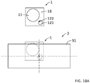
- the figure 8A and 8B more particularly illustrate third and fourth embodiments of the invention which have been obtained by deposition and etching steps which can be qualified as ordinary in the field of microelectronics. More particularly, the microelectromechanical system 1 according to the third embodiment illustrated in the figure 8A was obtained by the succession of steps illustrated by the Figures 9A, 10A , 11A , 12A , 13A , 14A and 15A and the micro electromechanical system 1 according to the fourth embodiment illustrated in the figure 8B was obtained by the succession of steps illustrated by the Figures 9B, 10B , 11B , 12B , 13B , 14B and 15B . Thus, two manufacturing processes are illustrated which each lead to one of the microelectromechanical systems 1 illustrated in the figure 8A and 8B .
- each of these etchings can be carried out by lithography, and preferably by plasma etching, or by wet chemical means.
- the fourth step of the manufacturing process of the micro electromechanical system 1 as illustrated in the figure 8A is illustrated on the Figure 12A . It includes the deposition of a layer 208 based on a polymer and intended to constitute the deformable membrane 12.
- This layer 208 is for example deposited by spin coating .
- the polymer on the basis of which the layer 208 is formed is for example based on PDMS.
- the fifth step of the manufacturing process of the micro electromechanical system 1 as illustrated in the figure 8A is illustrated on the Figure 13A . It comprises the formation of at least one spacer 306 intended to constitute at least a part of said at least one side wall 133 of the cavity 13.
- the formation of the spacer(s) may comprise the lamination of a photosensitive material on the basis of which the where the spacers are formed, the insolation, then the development of the photosensitive material.
- Said photosensitive material may be based on a polymer, and in particular based on siloxane.
- the lamination of the photosensitive material may comprise the lamination of a dry film of said material.
- this step includes the deposition of glue 210 at the top of each spacer 306, this deposition possibly being carried out by screen printing or by dispensing. It comprises the fixing, for example the gluing, on the top of the spacer(s) (possibly by means of the glue 210), of a second substrate 211 which can be structured so as to comprise at least one of a vent crossing 212 and a bottom stop 16 as described above. In an alternative embodiment, depending on the nature of the spacer, the latter can act as glue.
- the cavity 13 is formed which is opened by at least one through vent 212.
- the seventh step of the manufacturing process of the micro electromechanical system 1 as illustrated in the figure 8A is illustrated on the figure 15A . It comprises the filling, preferably under vacuum, of the cavity 13 with the deformable medium 14 as described above, for example by dispensing through the through vent 212. It also comprises the sealing of the at least one through vent 212, for example by dispensing with a sealing material 213 at the mouth of each through vent 212, the sealing material 213 being for example based on an epoxy adhesive.
- An additional step makes it possible to obtain the microelectromechanical system 1 as illustrated in the figure 8A . It includes the etching of the substrate 200. This etching can be performed by lithography, and preferably by plasma etching, or by wet chemical means. It then comprises the etching of the layer 202 and of the insulating layers 201, 203 so as to form at least one beam 305 of the electromechanical transducer 11, to expose a part of the deformable membrane 12 and to constitute all or part of the pin 122 and any side stops 15.
- the pin 122 takes the form of a stack extending directly from the deformable membrane 12 opposite the cavity 13 by successively presenting the material of the insulating layer 201, the material constituting the beam 305, the material of the insulating layer 203 and the material constituting the substrate 200. It can be seen that the pin 122 is not centered on the free zone 121.
- the possible lateral stops 15 each take the form of a stack extending, directly or indirectly, from the deformable membrane 12 opposite the cavity 13 by successively presenting the material of the insulating layer 201, the material constituting the beam 305, the material of the insulating layer 203 and the material constituting the substrate 200.
- each of these etchings can be carried out by lithography, and preferably by plasma etching, or by wet chemical means.
- the fourth step of the manufacturing process of the micro electromechanical system 1 as illustrated in the figure 8B is illustrated on the figure 12B . It comprises the deposition of a layer intended to constitute the beam 305 of the electromechanical transducer 11, this layer being for example based on amorphous silicon and which can be deposited by PVD. It may then comprise a step of planarization of the previously deposited layer. It then comprises an etching of the previously deposited layer so as to form at least one beam 305 of the electromechanical transducer 11. This etching being carried out for example by lithography, and preferably by plasma etching, or by wet chemical means.
- the formation of the spacer(s) 306 may comprise the lamination of a photosensitive material from which the spacer(s) are made, the insolation, then the development of the photosensitive material.
- Said photosensitive material may be based on a polymer, and in particular based on siloxane.
- the lamination of the photosensitive material may comprise the lamination of a dry film of said material.
- the sixth step of the manufacturing process of the micro electromechanical system 1 as illustrated in the figure 8B is illustrated on the Figure 14B . It includes, where appropriate, the deposition of glue 408 at the top of each spacer 306. According to an optional example, this deposition can be carried out by screen printing or by dispensing. It comprises the bonding, on the top of the spacer(s) 306 (possibly by means of the glue 408), of a second substrate 411 which can be structured so as to comprise at least one of a through vent 412 and a bottom stop 16 as described above. In an alternative embodiment, depending on the nature of the spacer, the latter can act as glue. At the end of this sixth step, the cavity 13 is formed which is opened by at least one through vent 412.
- the seventh step of the manufacturing process of the micro electromechanical system 1 as illustrated in the figure 8B is illustrated on the figure 15B . It comprises the filling, preferably under vacuum, of the cavity 13 with the deformable medium 14 as described above, for example by dispensing through the at least one through vent 212. It also comprises the leaktight closure of the at least one through vent 212, for example by dispensing with a sealing material 213 at least at the mouth of each through vent 212, the sealing material 213 being for example based on an epoxy glue.
- An additional step makes it possible to obtain the microelectromechanical system 1 as illustrated in the figure 8B . It includes the etching of the substrate 200. This etching can be performed by lithography, and preferably by plasma etching, or by wet chemical means. It then includes the etching of the insulating layer 401 so as to expose part of the deformable membrane 12 and to constitute all or part of the pin 122 and any lateral stops 15.
- the pin 122 takes the form of a stack extending directly from the deformable membrane 12 opposite the cavity 13 by successively presenting the material of the insulating layer 401 and the material constituting the substrate 200. It can be seen that the pin 122 is not centered on the free zone 121.
- the possible lateral abutments 15 each take the form of a stack extending, directly or indirectly, from the beam 305 opposite the cavity 13 by successively presenting the material of the insulating layer 401 and the material constituting the substrate 200.
- the figure 16 illustrates, in section, an embodiment corresponding to the embodiments illustrated in the figures 1 to 3A .
- the electromechanical transducer 11 does not surround the free zone 121 of the membrane 12.
- This embodiment makes it possible to have more freedom to adapt the dimension, the shape and the number of the free zones 121, without the electromechanical transducer 11 imposes no constraint on these parameters.
- this embodiment makes it possible to have a smaller extent of free zone 121 and therefore a greater deformation of the latter.
- the inclination that can be imposed on the pin 122 is then increased.
- Another interest is to allow movements along the axis in two opposite directions, i.e., upwards and downwards.
- a spacer 19 It can take the form of a pillar or a low wall. This spacer 19 makes it possible to support the membrane 12.
- the deformable medium 14 surrounds this spacer 19.
- This spacer 19 acts as a pillar inside the cavity 13. If necessary, the spacer 19 makes it possible, for example jointly with the portion of the cover 18 which overhangs it, to stiffen an outline of the electromechanical transducer 11, so that its deformation is as fully as possible translated into a deformation of the membrane 12.
- Several spacers 19 may be provided.
- the electromechanical transducer 11 is configured so as to deflect downwards when it is stressed, as is the case on the figure 9A .
- the structure of the micro-electromechanical system illustrated in this figure 16 it would be perfectly possible to modify this electromechanical transducer 11 so that they flex upwards when it is stressed, as is the case on the Figure 9B .
- the figure 17A illustrates an embodiment in which the electromechanical transducer entirely surrounds the free zone 121 of the membrane 12. This is also the case in the embodiments described on the figures 8A to 15B .
- FIGS. 1 to 6E and 16 illustrate embodiments in which the free zone 121 is remote from the electromechanical transducer 11. This is also the case on the figures 17B and 17C .
- a fixed portion separates the free zone 121 and the electromechanical transducer 11. This fixed portion can be formed at least in part by the cover 18.
- the electromechanical transducer 11 is partially surrounded by the free zone 121 of the membrane 12.
- a part of the electromechanical transducer 11 is integral with a housing of the electromechanical system 1, for example with its cover 18.
- Another part of the electromechanical transducer is surrounded by the free zone 121 of the membrane 12.
- the free zone 121 has a general “U” shape around the electromechanical transducer 11.
- Its central portion 125 then also has a general “U” shape.
- the outer perimeter 129 and the peripheral portion 126 surround the central portion 125.
- the pins 122 positioned on either side of the central portion 125 can therefore come into contact with each other when the free zone 121 deforms.
- the pins 122 then define a gripping line which extends along the central portion 125.
- this gripping line also forms a “U”. This makes it possible, for example, to adapt the gripping zone to specific shapes of objects which it is desired to grasp, capture or retain.
- the shapes of the free zone 121 of the membrane 12 can be adapted with a strong freedom according to the objectives which one seeks to achieve. These objectives concern, for example, the amplitude of the inclination of the pins 122 or the shape that one wishes to give to a gripping zone ensured by the pins 122.
- the free area 121 has a disc shape. Its central portion 125, its peripheral portion 126 and its outer periphery 129 then also have a disc or circle shape.
- the free zone 121 has an oblong or ellipsoid shape. Its central portion 125, its peripheral portion 126 and its outer periphery 129 then also have an oblong or ellipsoid shape.
- the free zone 121 has a polygonal shape, here a square. Its central portion 125, its peripheral portion 126 and its outer periphery 129 then also have a polygonal shape.
- the free zone 121 forms an open contour.
- this open outline forms a “U”.
- the shape of the electromechanical transducer 11 can be adapted as desired.
- the figures 17B and 17C illustrate embodiments comprising several electromechanical transducers 11a, 11b.
- the electromechanical transducers 11a, 11b can be separated from each other, for example by a cover portion 18. Their moving parts are then not in contact.
- the electromechanical transducers 11a, 11b can be juxtaposed. However, they are not entirely contiguous. Indeed, the piezoelectric materials of the two electromechanical transducers 11a, 11b must be separated in order to be able to be polarized individually.
- the piezoelectric material of a first electromechanical transducer 11b surrounds, at least partially, or even entirely, the piezoelectric material of one or more other electromechanical transducers 11a.
- the moving parts of these electromechanical transducers 11a, 11b are continuous.
- the number of electromechanical transducers 11 can be greater than two.
- the electromechanical transducers can be activated simultaneously or successively.
- the displacement amplitude of pin 122 induced by each electromechanical transducer 11 may be identical or different.
- electromechanical transducers 11 in the same electromechanical microsystem 1 allows varied operating modes.
- the electromechanical transducers 11a, 11b are configured so that, under stress, their moving parts induce deformations of the free zone 121 resulting in an inclination of the pin(s) 122 in the same direction. The total inclination of the pin(s) then results from the cumulative displacement of the moving parts of these electromechanical transducers 11a, 11b. This potentially makes it possible to limit the addressing voltage.
- the microelectromechanical system when the electromechanical transducers 11 can be activated independently of one another or successively, the microelectromechanical system then exhibits step-by-step operation. This makes it possible to control with even greater precision the inclination of the pawn or pawns.
- At least some of the electromechanical transducers 11a, 11b are configured so that, under stress, they induce an inclination of the peg(s) 122 in two opposite directions. These two electromechanical transducers 11a, 11b are therefore antagonistic.
- at least one of these electromechanical transducers makes it possible to tilt pin 122 in a first direction and at least one other of these electromechanical transducers 11a, 11b makes it possible to tilt pin 122 in a second direction opposite to the first direction. This makes it possible to further increase the amplitude of the inclination possible for the pin 122.
- each moving part or moving parts of the transducers illustrated in the Fig. 17C may be at least 5 times, even 10 times, even 20 times greater than the surface area of the free zones 121a, 121b of the deformable membrane 12.
- FIG. 18A Another aspect of the invention relates to an opto-electro-mechanical system 3.
- the opto-electro-mechanical microsystem 3 illustrated in this figure comprises at least one microelectromechanical system 1 as described above and at least one optical microsystem 31.
- the microelectromechanical system 1 is preferably mounted on a support of the opto-electromechanical microsystem 3.
- the optical microsystem 31 can comprise a silicon-based micro-mirror.
- pin 122 is not placed in the center of the mirror. This makes it possible to further increase the amplitude of the inclination of the mirror.
- the optical microsystem 31 can be mounted directly on the at least one electromechanical microsystem 1 or be mounted there via a frame. It may have dimensions substantially equal to 2 mm ⁇ 5 mm and/or, at most, a thickness of about 700 ⁇ m.
- the optical microsystem 31 can be attached, directly or indirectly, to the upper ends of the pegs. In this way, by driving all the pins in the same movement, the optical microsystem 31 is moved in a circular translation movement.
- An opto-electro-mechanical microsystem 3 is thus obtained which benefits from a large capacity for adapting its optical orientation.
- the invention makes it possible to obtain an inclination of one or more pins 122 with an angular movement whose amplitude is large and perfectly controlled. This makes it possible to obtain actuators, gripping devices, or even sensors, with large displacement and high precision.
- the microelectromechanical system 1 can be arranged in a self-assembly system of microelectronic components.
- a free end 122b of the pin 12 when the microelectromechanical system 1 performs a gripping function, provision can be made for a free end 122b of the pin 12 alone to enable an object to be captured.
- this free end 122b can have a suitable shape or material.
- the free end 122b can form a curved finger or hook for grasping an object. It can also present any other form complementary to the object in order to grasp the latter.
- the tip material free 122b of pawn 122 can contribute or alone ensure the capture of an object. Provision can for example be made to coat at least part of the pin 122 with an adhesive material or at least with a material that adheres with the material of the object to be captured. Provision can also be made for the pin 122 to comprise a magnetic or ferromagnetic material making it possible to capture an object by magnetic force.
Landscapes
- Engineering & Computer Science (AREA)
- Microelectronics & Electronic Packaging (AREA)
- Manufacturing & Machinery (AREA)
- Chemical & Material Sciences (AREA)
- Analytical Chemistry (AREA)
- Computer Hardware Design (AREA)
- Micromachines (AREA)
- Measuring Fluid Pressure (AREA)
Abstract
L'invention concerne un microsystème électromécanique 1 comprenant un transducteur électromécanique 11, une membrane déformable 12 et une cavité 13 contenant hermétiquement un milieu déformable 14 conservant un volume constant sous l'action d'un changement de pression externe. La membrane déformable forme une paroi de la cavité et présente au moins une zone libre 121 de se déformer de façon élastique. Le transducteur électromécanique est configuré de sorte que son mouvement soit fonction dudit changement de pression externe, et inversement. La zone libre coopère avec un organe externe 2 de sorte que sa déformation induise, ou soit induite par, un mouvement de l'organe externe. Le microsystème électromécanique 1 est ainsi apte à déplacer l'organe externe ou à capter un mouvement de cet organe. le microsystème électromécanique 1 comprend au moins un pion 122, configuré pour prendre appui sur une portion périphérique 126 de la zone libre 121 de sorte qu'une déformation de la zone libre 121 entraine une inclinaison du pion 122.The invention relates to a microelectromechanical system 1 comprising an electromechanical transducer 11, a deformable membrane 12 and a cavity 13 hermetically containing a deformable medium 14 maintaining a constant volume under the action of an external pressure change. The deformable membrane forms a wall of the cavity and has at least one free zone 121 to deform elastically. The electromechanical transducer is configured such that its movement is a function of said change in external pressure, and vice versa. The free zone cooperates with an external member 2 so that its deformation induces, or is induced by, a movement of the external member. The electromechanical microsystem 1 is thus able to move the external member or to pick up a movement of this member. the microelectromechanical system 1 comprises at least one pin 122, configured to bear on a peripheral portion 126 of the free zone 121 so that a deformation of the free zone 121 leads to an inclination of the pin 122.
Description
La présente invention concerne le domaine des microsystèmes électromécaniques. Elle trouve par exemple pour application particulièrement avantageuse l'actionnement ou le déplacement d'objets, y compris sur des distances relativement grandes. Elle trouve également pour application des dispositifs de préhension qui permettent la capture ou l'expulsion d'objets de petites tailles. L'invention trouve également pour application le domaine de la détection par contact. Elle pourra ainsi être mise en œuvre pour réaliser des capteurs.The present invention relates to the field of microelectromechanical systems. For example, it finds a particularly advantageous application in the actuation or displacement of objects, including over relatively long distances. It also finds for application gripping devices which allow the capture or expulsion of small objects. The invention also finds application in the field of detection by contact. It can thus be implemented to produce sensors.
Dans des applications variées, on peut avoir besoin de déplacer, capturer ou expulser des objets microscopiques, voire nanoscopiques, et/ou avoir besoin de capter des mouvements de tels objets. Il existe des microsystèmes qui permettent cela.In various applications, one may need to move, capture or expel microscopic or even nanoscopic objects, and/or need to capture movements of such objects. There are microsystems that allow this.
Lorsque ces microsystèmes sont des actionneurs ou des dispositifs de préhension, leurs performances sont évaluées notamment sur les paramètres suivants : l'amplitude du déplacement, la force déployée, la précision du déplacement généré ou encore la précision de la capture ou de l'expulsion d'un objet. Lorsque ces microsystèmes sont des capteurs, leurs performances sont évaluées notamment sur les paramètres suivants: la capacité à capter un mouvement sur une amplitude importante et la précision de la mesure.When these microsystems are actuators or gripping devices, their performance is evaluated in particular on the following parameters: the amplitude of the displacement, the force deployed, the precision of the displacement generated or the precision of the capture or expulsion of 'an object. When these microsystems are sensors, their performance is evaluated in particular on the following parameters: the ability to capture a movement over a large amplitude and the precision of the measurement.
Par ailleurs, que les microsystèmes soient des actionneurs, des dispositifs de préhension ou des capteurs, on recherche à ce qu'ils offrent de bonnes performances en termes d'encombrement, de consommation énergétique et de capacité à travailler en fréquence.Furthermore, whether the microsystems are actuators, gripping devices or sensors, it is sought that they offer good performance in terms of size, energy consumption and ability to work at frequency.
Toutes les solutions connues présentent des performances faibles pour l'un au moins de ces paramètres. Généralement, les microsystèmes existants présentent des performances trop peu satisfaisantes pour une combinaison de ces paramètres.All the known solutions exhibit poor performance for at least one of these parameters. Generally, existing microsystems exhibit performances that are too unsatisfactory for a combination of these parameters.
Un objet de la présente invention est de proposer un microsystème électromécanique qui présente des performances améliorées par rapport aux solutions existantes, au moins pour l'un des paramètres mentionnés ci-dessus, ou qui présente un meilleur compromis concernant au moins deux des paramètres susmentionnés.An object of the present invention is to provide a micro-electromechanical system which has improved performance compared to existing solutions, at least for one of the parameters mentioned above, or which has a better compromise with regard to at least two of the parameters mentioned above.
Les autres objets, caractéristiques et avantages de la présente invention apparaîtront à l'examen de la description suivante et des dessins d'accompagnement. Il est entendu que d'autres avantages peuvent être incorporés.The other objects, features and advantages of the present invention will become apparent from a review of the following description and the accompanying drawings. It is understood that other benefits may be incorporated.
Pour atteindre cet objectif, selon un mode de réalisation, on prévoit un microsystème électromécanique comprenant:
- au moins un transducteur électromécanique comprenant une partie mobile entre une position d'équilibre, hors sollicitation, et une position hors équilibre, sous sollicitation,
- au moins une membrane déformable,
- une cavité déformable, délimitée par des parois, au moins une partie de la membrane déformable formant au moins une partie d'une première paroi prises parmi lesdites parois de la cavité, la cavité étant configurée pour contenir hermétiquement un milieu déformable propre à conserver un volume sensiblement constant sous l'action d'un changement de pression externe exercée sur le milieu déformable à travers l'une des parois de la cavité.
- at least one electromechanical transducer comprising a movable part between a position of equilibrium, without stress, and a position out of equilibrium, under stress,
- at least one deformable membrane,
- a deformable cavity, delimited by walls, at least a part of the deformable membrane forming at least a part of a first wall taken from among the said walls of the cavity, the cavity being configured to hermetically contain a deformable medium suitable for maintaining a volume substantially constant under the action of a change in external pressure exerted on the deformable medium through one of the walls of the cavity.
La partie mobile du transducteur électromécanique est configurée de sorte que son mouvement soit fonction dudit changement de pression externe, ou inversement que son mouvement induise un changement de pression externe. Ladite au moins une partie de la membrane déformable présente au moins une zone libre de se déformer, de préférence de façon élastique, en fonction dudit changement de pression externe.The mobile part of the electromechanical transducer is configured so that its movement is a function of said change in external pressure, or conversely that its movement induces a change in external pressure. Said at least part of the deformable membrane has at least one zone free to deform, preferably elastically, depending on said change in external pressure.
La zone libre présente un pourtour externe et une portion périphérique qui s'étend depuis le pourtour externe et jusqu'à une portion centrale de la zone libre.The free zone has an outer periphery and a peripheral portion which extends from the outer periphery and to a central portion of the free zone.
Ainsi, le microsystème électromécanique proposé permet d'obtenir une inclinaison du pion selon un angle présentant une amplitude élevée relativement à la déformation de la membrane. Il est alors possible, même avec un microsystème électromécanique de petites dimensions d'obtenir de grands débattements. En particulier, la deuxième extrémité du pion, c'est-à-dire l'extrémité du pion opposée à son extrémité en appui sur la membrane, se déplace selon une grande course.Thus, the microelectromechanical system proposed makes it possible to obtain an inclination of the pin according to an angle having a high amplitude relative to the deformation of the membrane. It is then possible, even with a micro-electromechanical system of small dimensions, to obtain large deflections. In particular, the second end of the pin, that is to say the end of the pin opposite to its end resting on the membrane, moves along a long stroke.
Typiquement, le déplacement de la deuxième extrémité de pion peut s'effectuer sur une longueur de course pouvant s'exprimer sous forme angulaire. Typiquement, la deuxième extrémité du pion se déplace d'un angle d'au moins 45° et de préférence comprise entre 0° et 90°.Typically, the displacement of the second end of the pin can take place over a stroke length which can be expressed in angular form. Typically, the second end of the pin moves through an angle of at least 45° and preferably between 0° and 90°.
Le microsystème électromécanique proposé présente donc une solution particulièrement efficace pour réaliser :
- un actionneur à grand débattement. Un tel actionneur autorise le déplacement d'un objet ou d'un organe externe déplacé par le ou les pions, typiquement avec une amplitude de l'ordre de 100 µm.
- un dispositif de préhension. En prévoyant plusieurs pions sur la zone libre de la membrane, en particulier sur sa portion périphérique, on parvient à ce que les extrémités des différents pions se rapprochent pour permettre de saisir, capturer ou retenir un objet entre les pions. Inversement, on peut commander l'éloignement des pions pour permettre de libérer ou expulser un objet. De même en prévoyant au moins un pion dont une extrémité libre est conformée pour coopérer avec un objet pour le saisir, le déplacement du pion permet de capturer ou de relâcher un objet. On peut également prévoir que le matériau du pion permette la capture d'un objet, par des forces d'adhésion ou des forces magnétiques.
- un capteur, autorisant typiquement à capter un déplacement imposé à au moins un pion. Ce déplacement peut être un déplacement selon une trajectoire courbe.
- a long travel actuator. Such an actuator authorizes the movement of an object or of an external member moved by the pawn(s), typically with an amplitude of the order of 100 μm.
- a gripping device. By providing several pins on the free zone of the membrane, in particular on its peripheral portion, it is possible that the ends of the different pawns come together to allow grasping, capturing or retaining an object between the pawns. Conversely, it is possible to control the removal of the pawns to enable an object to be released or expelled. Similarly, by providing at least one peg, one free end of which is shaped to cooperate with an object in order to grasp it, the movement of the peg makes it possible to capture or release an object. Provision can also be made for the material of the pin to allow the capture of an object, by adhesion forces or magnetic forces.
- a sensor, typically allowing to capture a displacement imposed on at least one pawn. This movement can be a movement along a curved trajectory.
Le microsystème électromécanique tel qu'introduit ci-dessus est ainsi apte à déplacer le pion ou à capter un mouvement imposé à ce dernier, et ce en présentant, de façon aisément modulable en fonction des applications visées, une capacité suffisante en termes d'amplitude de déplacement et/ou une capacité suffisante en termes de force déployée et/ou une capacité de captation de mouvement, voire de capture, d'un objet et/ou une capacité suffisante à travailler en fréquence et/ou une taille compatible avec les applications visées, et/ou une consommation en énergie réduite.The microelectromechanical system as introduced above is thus able to move the pin or to pick up a movement imposed on the latter, and this by presenting, in an easily adjustable manner depending on the targeted applications, a sufficient capacity in terms of amplitude. of movement and/or a sufficient capacity in terms of force deployed and/or a capacity to capture the movement, or even capture, of an object and/or a sufficient capacity to work in frequency and/or a size compatible with the applications targeted, and/or reduced energy consumption.
Un autre aspect de l'invention concerne un système ou un microsystème opto-électro-mécanique comprenant au moins un microsystème électromécanique tel qu'introduit ci-dessus et au moins un microsystème optique.Another aspect of the invention relates to an opto-electromechanical system or microsystem comprising at least one electromechanical microsystem as introduced above and at least one optical microsystem.
De préférence, le microsystème optique comprend au moins un miroir, de préférence à base de silicium. Le système opto-électro-mécanique est configuré de sorte à ce que le mouvement de la partie mobile du transducteur électromécanique provoque un déplacement, de préférence une inclinaison, de l'au moins un miroir.Preferably, the optical microsystem comprises at least one mirror, preferably based on silicon. The opto-electro-mechanical system is configured so that the movement of the mobile part of the electromechanical transducer causes a displacement, preferably an inclination, of the at least one mirror.
Un autre aspect de l'invention concerne un procédé de fabrication d'un microsystème électromécanique tel qu'introduit ci-dessus, comprenant, voire étant limité à, des étapes de dépôt et de gravure ordinaires en microélectronique. Le microsystème électromécanique peut en effet être fabriqué par des moyens ordinaires de la microélectronique, ce qui confère à son fabricant tous les avantages découlant de l'utilisation de ces moyens, dont une grande latitude en termes de dimensionnement, d'énergie d'adhésion entre les différents dépôts, d'épaisseur des différents dépôts, d'étendue de gravure, etc.Another aspect of the invention relates to a method for manufacturing a microelectromechanical system as introduced above, comprising, or even being limited to, ordinary deposition and etching steps in microelectronics. The microelectromechanical system can in fact be manufactured by ordinary microelectronics means, which gives its manufacturer all the advantages deriving from the use of these means, including great latitude in terms of dimensioning, adhesion energy between the different deposits, the thickness of the different deposits, the extent of etching, etc.
Selon un exemple le procédé de fabrication du microsystème électromécanique comprend les étapes suivantes :
- une étape de formation, sur un substrat, d'une portion au moins du transducteur électromécanique, puis
- une étape de dépôt de la membrane déformable, puis
- une étape de formation d'une cavité ouverte sur la membrane déformable, puis
- une étape de remplissage avec le milieu déformable et de fermeture de la cavité, et
- une étape de gravure du substrat pour former une face avant (FAV) du microsystème électromécanique.
- a step of forming, on a substrate, at least a portion of the electromechanical transducer, then
- a step of deposition of the deformable membrane, then
- a step of forming an open cavity on the deformable membrane, then
- a step of filling with the deformable medium and closing the cavity, and
- a step of etching the substrate to form a front face (FAV) of the microelectromechanical system.
Les buts, objets, ainsi que les caractéristiques et avantages de l'invention ressortiront mieux de la description détaillée de modes de réalisation de cette dernière qui sont illustrés par les dessins d'accompagnement suivants dans lesquels :
- La
figure 1 est un schéma de principe d'une vue en coupe d'un microsystème électromécanique selon un premier mode de réalisation de l'invention. - La
figure 2 est un schéma de principe en vue du dessus du microsystème électromécanique illustré enfigure 1 . Sur lesfigures 1 , le microsystème électromécanique est illustré dans une configuration dans laquelle la membrane n'est pas déformée.et 2 - La
figure 3A représente le microsystème illustré enfigures 1 , dans une première configuration de déformation de la membrane.et 2 - La
figure 3B représente le microsystème illustré enfigures 1 , dans une deuxième configuration de déformation de la membrane.et 2 - La
figure 4 est un schéma de principe d'une vue en coupe d'un microsystème électromécanique selon un deuxième mode de réalisation de l'invention. Dans ce deuxième mode de réalisation, la zone libre de la membrane coopère avec plusieurs pions. - La
figure 5 est un schéma de principe en vue du dessus du microsystème électromécanique illustré enfigure 4 . Sur lesfigures 4 et 5 , le microsystème électromécanique est illustré dans une configuration dans laquelle la membrane n'est pas déformée. - Les
figures 6A à 6E représentent le microsystème illustré enfigures 4 et 5 , dans des configurations de déformation de la membrane. - Les
figures 6A et 6B illustrent une configuration dans laquelle les extrémités libres des pions sont éloignées les unes des autres, par exemple pour capturer un objet. - Les
figures 6C à 6E illustrent une configuration dans laquelle les extrémités libres des pions sont rapprochées les unes des autres, par exemple pour permettre la saisie d'un objet ou empêcher la libération d'un objet capturé. - Les
figures 7A et 7B sont des schémas de principe, vue en coupe, d'un microsystème électromécanique selon un autre mode de réalisation de l'invention dans lequel l'actionneur électromécanique entoure la zone libre de la membrane. Dans ce mode de réalisation, des butées latérales sont prévues. Sur lafigure 7A , la membrane est représentée déformée selon une première configuration. Sur lafigure 7B , la membrane est représentée déformée selon une deuxième configuration. - La
figure 7C est un schéma de principe en vue du dessus du microsystème électromécanique illustré enfigures 7A et 7B . - Les
figures 8A et8B sont des schémas, plus détaillés que ceux desfigures 7A et 7B , et représentant des microsystèmes électromécaniques structurellement proches de ceux illustrés sur lesfigures 7A et 7B respectivement. - Les
figures 9A à 15A représentent schématiquement des étapes d'un exemple de procédé de réalisation d'un microsystème électromécanique illustré enfigure 8A . - Les
figures 9B à 15B représentent schématiquement des étapes d'un exemple de procédé de réalisation d'un microsystème électromécanique illustré enfigure 8B . - La
figure 16 représente schématiquement un microsystème électromécanique proche de celui illustré enfigure 1 , mais avec un niveau de détail plus élevé. - Les
figures 17A à 17D représentent schématiquement des variantes du microsystème opto-électro-mécanique selon l'invention. - La
figure 18A représente schématiquement un exemple de microsystème électromécanique comprenant un microsystème électromécanique.
- The
figure 1 is a block diagram of a sectional view of a micro-electromechanical system according to a first embodiment of the invention. - The
figure 2 is a block diagram in top view of the micro electromechanical system illustrated infigure 1 . On thefigures 1 and 2 , the microelectromechanical system is illustrated in a configuration in which the membrane is not deformed. - The
Figure 3A represents the microsystem illustrated infigures 1 and 2 , in a first membrane deformation configuration. - The
Figure 3B represents the microsystem illustrated infigures 1 and 2 , in a second membrane deformation configuration. - The
figure 4 is a block diagram of a sectional view of a micro-electromechanical system according to a second embodiment of the invention. In this second embodiment, the free zone of the membrane cooperates with several pions. - The
figure 5 is a block diagram in top view of the micro electromechanical system illustrated infigure 4 . On thefigures 4 and 5 , the microelectromechanical system is illustrated in a configuration in which the membrane is not deformed. - The
figures 6A to 6E represent the microsystem illustrated infigures 4 and 5 , in membrane deformation configurations. - The
figures 6A and 6B illustrate a configuration in which the free ends of the pawns are moved away from each other, for example to capture an object. - The
figures 6C to 6E illustrate a configuration in which the free ends pawns are brought closer to each other, for example to allow the seizure of an object or prevent the release of a captured object. - The
figures 7A and 7B are block diagrams, cross-sectional view, of a micro-electromechanical system according to another embodiment of the invention in which the electromechanical actuator surrounds the free zone of the membrane. In this embodiment, side stops are provided. On theFigure 7A , the membrane is shown deformed according to a first configuration. On thefigure 7B , the membrane is shown deformed according to a second configuration. - The
Fig. 7C is a block diagram in top view of the micro electromechanical system illustrated infigures 7A and 7B . - The
figure 8A and8B are diagrams, more detailed than those of thefigures 7A and 7B , and representing micro-electromechanical systems structurally close to those illustrated on thefigures 7A and 7B respectively. - The
figures 9A to 15A schematically represent steps of an exemplary method for producing a microelectromechanical system illustrated infigure 8A . - The
figures 9B to 15B schematically represent steps of an exemplary method for producing a microelectromechanical system illustrated infigure 8B . - The
figure 16 schematically represents a micro-electromechanical system similar to that illustrated infigure 1 , but with a higher level of detail. - The
figures 17A to 17D schematically represent variants of the opto-electro-mechanical microsystem according to the invention. - The
Fig. 18A schematically represents an example of a micro-electromechanical system comprising a micro-electromechanical system.
Les dessins sont donnés à titre d'exemples et ne sont pas limitatifs de l'invention. Ils constituent des représentations schématiques de principe destinées à faciliter la compréhension de l'invention et ne sont pas nécessairement à l'échelle des applications pratiques. En particulier, les épaisseurs des différentes couches, parois et organes illustrés ne sont pas nécessairement représentatives de la réalité.The drawings are given by way of examples and do not limit the invention. They constitute schematic representations of principle intended to facilitate understanding of the invention and are not necessarily at the scale of practical applications. In particular, the thicknesses of the various layers, walls and organs illustrated are not necessarily representative of reality.
Selon un exemple, en l'absence de déformation, la zone libre de la membrane s'étend principalement dans un plan (xy), dit plan hors déformation ou plan au repos, et la perpendiculaire à la tangente en un point donné de la zone libre s'étend selon une direction T1 perpendiculaire au plan hors déformation.According to an example, in the absence of deformation, the free zone of the membrane extends mainly in a plane (xy), called the plane without deformation or plane at rest, and the perpendicular to the tangent at a given point of the zone free extends in a direction T1 perpendicular to the plane outside the deformation.
Selon un exemple, lorsque la membrane se déforme, la perpendiculaire à la tangente en un point donné de la portion périphérique de la zone libre s'étend selon une direction Ti, inclinée par rapport à la direction T1, d'un angle ai (l'angle ai étant mesuré dans un plan perpendiculaire au plan hors déformation).According to one example, when the membrane deforms, the perpendicular to the tangent at a given point of the peripheral portion of the free zone extends along a direction Ti, inclined with respect to direction T1, by an angle ai (the angle ai being measured in a plane perpendicular to the plane outside the deformation).
Selon un exemple, l'angle ai augmente au fur à mesure que l'on s'éloigne de la portion centrale et que l'on se rapproche du pourtour externe de la zone libre.According to one example, the angle α increases as one moves away from the central portion and as one approaches the outer periphery of the free zone.
Selon un exemple, le microsystème électromécanique est configuré de sorte qu'une déformation de la zone libre de la membrane entraine une inclinaison du pion dans un plan perpendiculaire à un plan (xy) dans lequel s'étend principalement une face externe de la membrane lorsque la membrane n'est pas déformée.According to one example, the microelectromechanical system is configured so that a deformation of the free zone of the membrane leads to an inclination of the pin in a plane perpendicular to a plane (xy) in which an outer face of the membrane mainly extends when the membrane is not deformed.
Selon un exemple, l'inclinaison peut être mesurée par un angle α contenu dans un plan perpendiculaire au plan xy.According to one example, the inclination can be measured by an angle α contained in a plane perpendicular to the xy plane.
Selon un exemple, le pion s'étend principalement selon une direction longitudinale. Lorsque la membrane n'est pas déformée, la direction longitudinale du pion est sensiblement perpendiculaire à un plan (xy) dans lequel s'étend principalement une face externe de la membrane lorsque la membrane n'est pas déformée. Le pion peut présenter une forme cylindrique. Selon un mode de réalisation alternatif, le pion ne présente pas une forme cylindrique. Il peut présenter une forme courbe par exemple.According to one example, the pin extends mainly in a longitudinal direction. When the membrane is not deformed, the longitudinal direction of the pin is substantially perpendicular to a plane (xy) in which mainly extends an outer face of the membrane when the membrane is not deformed. The pin may have a cylindrical shape. According to an alternative embodiment, the pin does not have a cylindrical shape. It may have a curved shape for example.
Selon un exemple, le pion présente une première extrémité par laquelle il prend appui sur la portion périphérique de la zone libre et une deuxième extrémité opposée à la première extrémité.According to one example, the pin has a first end by which it rests on the peripheral portion of the free zone and a second end opposite the first end.
Selon un exemple, le microsystème électromécanique est configuré de sorte qu'une déformation de la zone libre de la membrane entraine une inclinaison de la première extrémité en direction de la portion centrale de la zone libre.According to one example, the microelectromechanical system is configured so that a deformation of the free zone of the membrane causes the first end to tilt in the direction of the central portion of the free zone.
Selon un exemple, le pion s'étend entre la première extrémité et la deuxième extrémité principalement selon une direction longitudinale. Alternativement le pion présente une forme courbe ou s'étend selon plusieurs directions différentes.According to one example, the pin extends between the first end and the second end mainly in a longitudinal direction. Alternatively, the pawn has a curved shape or extends in several different directions.
Selon un exemple, la zone libre présente une portion centrale s'étendant depuis un centre de la zone libre et une portion périphérique disposée autour de la portion centrale.According to one example, the free zone has a central portion extending from a center of the free zone and a peripheral portion arranged around the central portion.
Selon un exemple, la zone périphérique est continue. Elle présente un contour plein. Alternativement, elle présente un contour ouvert.According to one example, the peripheral zone is continuous. It has a full outline. Alternatively, it has an open contour.
Selon un exemple, la portion centrale comprend un centre de la zone libre, le centre correspond par exemple au barycentre de la zone libre.According to one example, the central portion comprises a center of the free zone, the center corresponds for example to the center of gravity of the free zone.
Selon un exemple, la zone libre forme un disque, une ellipse ou un polygone et ledit centre correspond au barycentre de la zone libre.According to one example, the free zone forms a disc, an ellipse or a polygon and said center corresponds to the barycenter of the free zone.
Selon un exemple, la zone libre est délimitée par un pourtour externe, le pion étant situé à une distance minimale D122 du pourtour externe, telle que D122 est inférieure à k fois une distance D124 :
- D122 étant mesurée entre le pion et le point du pourtour externe le plus proche du pion, et
- La distance D124 étant mesurée entre ce même point et le centre de la zone libre,
- k étant inférieur à 0,7, de préférence k étant inférieur à 0,5, de préférence k étant inférieur à 0,3.
- D122 being measured between the peg and the point of the outer circumference closest to the peg, and
- The distance D124 being measured between this same point and the center of the free zone,
- k being less than 0.7, preferably k being less than 0.5, preferably k being less than 0.3.
Selon un mode de réalisation alternatif, la portion centrale ne forme pas un disque, une ellipse ou un polygone. La portion centrale peut entourer au moins partiellement le transducteur électromécanique. La portion centrale peut par exemple présenter une forme allongée. Cette forme allongée peut s'étendre selon plusieurs segments présentant des directions différentes.According to an alternative embodiment, the central portion does not form a disc, an ellipse or a polygon. The central portion can at least partially surround the electromechanical transducer. The central portion may for example have an elongated shape. This elongated shape can extend along several segments presenting different directions.
Selon un exemple, le microsystème électromécanique comprend une pluralité de pions, prenant chacun appui sur la portion périphérique de la zone libre de sorte qu'une déformation de la zone libre de la membrane entraine une inclinaison des pions.According to one example, the microelectromechanical system comprises a plurality of pins, each resting on the peripheral portion of the free zone so that a deformation of the free zone of the membrane causes the pins to tilt.
Selon un exemple, les pions présentent une extrémité libre, opposée à l'extrémité par laquelle ils prennent appui sur la portion périphérique de la zone libre, les pions étant conformés de sorte qu'une déformation de la zone libre de la membrane entraine sélectivement un rapprochement ou un éloignement, de leurs extrémités libres.According to one example, the pins have a free end, opposite the end by which they bear on the peripheral portion of the free zone, the pins being shaped so that a deformation of the free zone of the membrane selectively causes a bringing together or moving away from their free ends.
Selon un exemple, les pions sont conformés de sorte qu'une déformation de la zone libre de la membrane entraine sélectivement une mise en contact ou un éloignement des extrémités libres des pions.According to one example, the pawns are shaped so that a deformation of the free zone of the membrane selectively causes the free ends of the pawns to come into contact with or move away from each other.
Selon un exemple, les pions sont répartis sur la portion périphérique de sorte que le rapprochement de leurs extrémités libres permette de saisir entre les extrémités libres et/ou de retenir entre la membrane et les pions un objet externe au microsystème électromécanique. Le rapprochement de leurs extrémités libres permet de former une cage au-dessus de la zone libre de la membrane.According to one example, the pins are distributed over the peripheral portion so that the bringing together of their free ends makes it possible to grasp between the free ends and/or to retain between the membrane and the pins an object external to the microelectromechanical system. Bringing their free ends together makes it possible to form a cage above the free zone of the membrane.
Ce mode de réalisation permet d'obtenir un dispositif de préhension particulièrement fiable et précis. En outre, le grand débattement angulaire des pions, permet de capturer et de relâcher des objets de tailles relativement grandes par rapport à la taille des pions et à la taille du microsystème électromécanique.This embodiment makes it possible to obtain a particularly reliable and precise gripping device. In addition, the large angular deflection of the pawns makes it possible to capture and release objects of relatively large sizes compared to the size of the pawns and the size of the microelectromechanical system.
Dans ce mode de réalisation, l'objet n'est pas fixé au microsystème électromécanique. A fortiori, il n'est pas fixé aux pions.In this embodiment, the object is not fixed to the microelectromechanical system. A fortiori, it is not fixed to the pawns.
Selon un autre mode de réalisation, l'objet est un organe externe.According to another embodiment, the object is an external organ.
Selon un exemple, le ou les pions sont configurés pour coopérer avec un objet formant un organe externe de sorte que le mouvement de la partie mobile du transducteur électromécanique soit fonction d'un déplacement du ou des pions entrainés par l'organe externe ou inversement que le mouvement de la partie mobile du transducteur électromécanique induise un déplacement, en particulier une inclinaison, de l'organe externe par l'intermédiaire du pion.According to one example, the pawn or pawns are configured to cooperate with an object forming an external member such that the movement of the movable part of the electromechanical transducer is a function of a displacement of the pin(s) driven by the external member or, conversely, that the movement of the movable part of the electromechanical transducer induces a displacement, in particular an inclination, of the external organ via the pion.
Ce mode de réalisation permet d'obtenir un actionneur fiable et précis ou un capteur. Le grand débattement angulaire des pions, permet un déplacement de l'organe externe sur une course relativement grande par rapport à la taille du ou des pions et à la taille du microsystème électromécanique.This embodiment provides a reliable and accurate actuator or sensor. The large angular travel of the pins allows movement of the external member over a relatively large stroke compared to the size of the pin(s) and the size of the microelectromechanical system.
Le ou les pions peuvent être configurés pour coopérer avec l'organe externe par l'intermédiaire d'un guide solidaire de l'organe externe, de sorte à permettre un positionnement automatique de l'organe externe sur le ou les pions.The peg(s) can be configured to cooperate with the external member via a guide secured to the outer member, so as to allow automatic positioning of the external member on the peg(s).
Le ou les pions peuvent être configurés pour pouvoir être solidarisés avec l'organe externe par collage ou magnétisme, l'énergie d'adhérence du ou des pions sur la zone libre de la membrane déformable étant de préférence supérieure à celle du pion ou des pions sur l'organe externe. Une solidarisation, éventuellement amovible, du ou des pions et de l'organe externe est ainsi prévue qui est largement modulable en termes de force de retenue.The pawn(s) can be configured to be able to be secured with the external member by bonding or magnetism, the adhesion energy of the pawn(s) on the free zone of the deformable membrane preferably being greater than that of the pawn or pawns on the external organ. An attachment, optionally removable, of the peg(s) and the external member is thus provided which is largely adjustable in terms of retaining force.
Selon un exemple, le microsystème électromécanique comprend en outre au moins une butée latérale, de préférence supportée par ladite première paroi de la cavité, configurée pour guider le mouvement de l'organe externe.According to one example, the microelectromechanical system further comprises at least one lateral abutment, preferably supported by said first wall of the cavity, configured to guide the movement of the external member.
Selon un exemple, le pion s'étend depuis la zone libre de la membrane déformable au-delà de ladite au moins une butée latérale. Selon un exemple alternatif, le pion s'étend depuis la zone libre de la membrane déformable en-deçà de ladite butée latérale.According to one example, the pin extends from the free zone of the deformable membrane beyond said at least one lateral stop. According to an alternative example, the pin extends from the free zone of the deformable membrane below said lateral stop.
Selon un exemple, le pion est fixé sur ladite zone libre, de préférence au contact directe de ladite zone libre.According to one example, the pin is fixed on said free zone, preferably in direct contact with said free zone.
Selon un exemple, le microsystème électromécanique comprend une pluralité de transducteurs électromécaniques.According to one example, the micro electromechanical system comprises a plurality of electromechanical transducers.
Selon un mode de réalisation, les transducteurs électromécaniques sont séparés les uns des autres. Leurs parties mobiles ne sont pas en contact. Alternativement, ils sont jointifs.According to one embodiment, the electromechanical transducers are separated from each other. Their moving parts are not in contact. Alternatively, they are contiguous.
Selon un exemple, un transducteur électromécanique entoure, au moins partiellement, voire entièrement, un ou plusieurs autres actionneurs électromécaniques, en particulier leur partie mobile. En outre, ils peuvent être actionnés indépendamment les uns des autres.According to one example, an electromechanical transducer surrounds, at least partially, or even entirely, one or more other electromechanical actuators, in particular their moving part. Furthermore, they can be operated independently of each other.
De préférence, chaque transducteur électromécanique présente une partie mobile configurée de sorte que son mouvement soit fonction dudit changement de pression externe, ou inversement que son mouvement induise un changement de pression externe exercée sur le milieu déformable à travers l'une des parois de la cavité.Preferably, each electromechanical transducer has a movable part configured so that its movement is a function of said change in external pressure, or conversely that its movement induces a change in external pressure exerted on the deformable medium through one of the walls of the cavity. .
Ainsi, le microsystème électromécanique comporte plusieurs transducteurs électromécaniques pour une cavité.Thus, the microelectromechanical system comprises several electromechanical transducers for a cavity.
Selon un exemple, au moins certains des transducteurs électromécaniques de ladite pluralité sont configurés pour que, sous sollicitation, leurs parties mobiles, induisent des déformations de la zone libre de la membrane entrainant une inclinaison de l'au moins un pion dans un même sens.According to one example, at least some of the electromechanical transducers of said plurality are configured so that, under stress, their moving parts induce deformations of the free zone of the membrane causing the at least one pin to tilt in the same direction.
Ainsi, au moins certains de ces transducteurs électromécaniques permettent chacun de déplacer l'au moins un pion selon une même direction et chacun sur une amplitude. L'inclinaison totale du pion résulte du cumul du déplacement des parties mobiles de ces transducteurs électromécaniques. Le microsystème électromécanique présente ainsi un fonctionnement pas à pas ; cela permet de limiter la tension d'adressage.Thus, at least some of these electromechanical transducers each make it possible to move the at least one pawn in the same direction and each over an amplitude. The total inclination of the pin results from the cumulative displacement of the moving parts of these electromechanical transducers. The microelectromechanical system thus has a step-by-step operation; this makes it possible to limit the addressing voltage.
Les transducteurs électromécaniques peuvent être sollicités simultanément ou successivement. L'amplitude de déplacement du pion induite par chaque transducteur électromécanique peut être identique ou différente.The electromechanical transducers can be activated simultaneously or successively. The displacement amplitude of the pion induced by each electromechanical transducer can be identical or different.
Selon un exemple, au moins certains des transducteurs électromécaniques de ladite pluralité sont configurés pour que, sous sollicitation, leurs parties mobiles, induisent des déformations de la zone libre de la membrane entrainant une inclinaison de l'au moins un pion dans deux sens opposés.According to one example, at least some of the electromechanical transducers of said plurality are configured so that, under stress, their moving parts induce deformations of the free zone of the membrane causing the at least one pin to tilt in two opposite directions.
Ainsi, au moins deux de ces transducteurs électromécaniques permettent de déplacer l'au moins un pion selon deux directions opposées. Ces deux transducteurs électromécaniques sont donc antagonistes. Ainsi, au moins l'un de ces transducteurs électromécaniques permet d'incliner le pion selon un premier sens et au moins un autre de ces transducteurs électromécaniques permet d'incliner le pion selon un deuxième sens opposé au premier sens. Cela permet d'augmenter encore l'amplitude de l'inclinaison possible pour le pion.Thus, at least two of these electromechanical transducers make it possible to move the at least one pin in two opposite directions. These two electromechanical transducers are therefore antagonistic. Thus, at least one of these electromechanical transducers makes it possible to tilt the pin in a first direction and at least one other of these electromechanical transducers makes it possible to tilt the pin in a second direction opposite to the first direction. This makes it possible to further increase the amplitude of the inclination possible for the pawn.
Ces deux transducteurs électromécaniques antagonistes peuvent être séparés l'un de l'autre d'une distance non nulle. Alternativement, l'un de ces transducteurs électromécaniques peut entourer, de préférence entièrement, l'autre transducteur électromécanique. Selon un autre mode de réalisation un même transducteur permet d'effectuer ces deux mouvements alternatifs. On pourra pour cela utiliser un transducteur en AIN par exemple.These two opposing electromechanical transducers can be separated from each other by a non-zero distance. Alternatively, one of these electromechanical transducers can surround, preferably entirely, the other electromechanical transducer. According to another embodiment, the same transducer makes it possible to perform these two alternating movements. It is possible for this to use an AlN transducer for example.
Selon un exemple, le microsystème électromécanique comprend plusieurs zones libres, séparées les unes des autres d'une distance non nulle.According to one example, the microelectromechanical system comprises several free zones, separated from each other by a non-zero distance.
Ces zones libres peuvent être formées par une même membrane. Alternativement, ces zones libres peuvent être formées par des membranes distinctes.These free zones can be formed by the same membrane. Alternatively, these free zones can be formed by distinct membranes.
Selon un exemple, la zone libre est libre de se déformer, de préférence de façon élastique, en fonction dudit changement de pression externe.According to one example, the free zone is free to deform, preferably elastically, depending on said change in external pressure.
Le microsystème électromécanique tel qu'introduit ci-dessus est de préférence exempt d'élément optique, telle qu'une lentille, notamment à focale variable.The microelectromechanical system as introduced above is preferably free of optical element, such as a lens, in particular with variable focal length.
Le pion n'est pas fixé au centre de la zone libre de la membrane déformable. De la sorte, le mouvement du pion n'est pas un mouvement de translation perpendiculaire à la paroi de la cavité qui est en partie formée par la membrane déformable.The pin is not fixed in the center of the free zone of the deformable membrane. In this way, the movement of the pin is not a translational movement perpendicular to the wall of the cavity which is partly formed by the deformable membrane.
Au moins une partie du transducteur électromécanique forme une partie de la paroi de la cavité qui est en partie formée par la membrane déformable. Le microsystème électromécanique selon cette caractéristique présente une structure non-traversante, laissant libre les autres parois de la cavité de sorte à pouvoir y réaliser d'autres fonctions ou de sorte à leur permettre de rester inertes, pour une capacité d'intégration accrue notamment dans un microsystème opto-électro-mécanique.At least a part of the electromechanical transducer forms a part of the wall of the cavity which is partly formed by the deformable membrane. The microelectromechanical system according to this characteristic has a non-through structure, leaving the other walls of the cavity free so as to be able to perform other functions therein or so as to allow them to remain inert, for an increased integration capacity in particular in an opto-electro-mechanical microsystem.
Le transducteur électromécanique peut s'étendre, directement ou indirectement, sur la membrane déformable, et de préférence autour de la zone libre de la membrane déformable. En outre, le transducteur électromécanique peut prendre une forme annulaire dont le centre circulaire défini l'étendue de la zone libre de la membrane déformable.The electromechanical transducer can extend, directly or indirectly, over the deformable membrane, and preferably around the free zone of the deformable membrane. Furthermore, the electromechanical transducer can take an annular shape, the circular center of which defines the extent of the free zone of the deformable membrane.
La partie mobile du transducteur électromécanique peut présenter une surface au moins deux fois supérieure, voire au moins 5 fois supérieure, et de préférence au moins dix fois supérieure à une surface de la zone libre de la membrane déformable, voire à la surface des zones libres de la membrane déformable. Plus la surface du transducteur est importante par rapport à la surface de la zone libre, plus l'amplitude de déformation de la zone libre de la membrane sera importante.The mobile part of the electromechanical transducer may have a surface at least twice greater, or even at least 5 times greater, and preferably at least ten times greater than a surface of the free zone of the deformable membrane, or even the surface of the free zones. of the deformable membrane. The greater the surface of the transducer relative to the surface of the free zone, the greater the amplitude of deformation of the free zone of the membrane.
La membrane déformable est de préférence configurée de sorte que sa zone libre soit capable de se déformer avec une amplitude d'au moins 50 µm, voire d'au moins 100µm, voire d'au moins 1000µm selon une direction perpendiculaire au plan dans lequel elle s'étend principalement lorsqu'elle est au repos. Sans se déchirer et/ou sans usure significative, le microsystème électromécanique offre ainsi la capacité à satisfaire de nombreuses et diverses applications nécessitant un grand débattement, ce dernier étant défini le cas échéant par domaine technique concerné.The deformable membrane is preferably configured so that its free zone is capable of deforming with an amplitude of at least 50 μm, or even at least 100 μm, or even at least 1000 μm in a direction perpendicular to the plane in which it stretches mainly when at rest. Without tearing and/or without significant wear, the microelectromechanical system thus offers the ability to satisfy many and various applications requiring a large deflection, the latter being defined, where appropriate, by technical field concerned.
Selon un exemple, au moins une partie du transducteur électromécanique forme une partie de ladite première paroi de la cavité.According to one example, at least a part of the electromechanical transducer forms part of said first wall of the cavity.
Selon un exemple, le transducteur électromécanique s'étend, directement sur la membrane déformable, c'est-à-dire que le transducteur électromécanique est directement au contact de la membrane déformable. Alternativement, le transducteur électromécanique s'étend indirectement sur la membrane déformable c'est-à-dire qu'au moins un élément ou une couche intermédiaire est disposé entre le transducteur électromécanique et la membrane déformable. De préférence, le transducteur électromécanique s'étend autour de la zone libre de la membrane déformable.According to one example, the electromechanical transducer extends directly over the deformable membrane, ie the electromechanical transducer is directly in contact with the deformable membrane. Alternatively, the electromechanical transducer extends indirectly over the deformable membrane, ie at least one element or an intermediate layer is placed between the electromechanical transducer and the deformable membrane. Preferably, the electromechanical transducer extends around the free zone of the deformable membrane.
Selon un exemple, le transducteur électromécanique entoure entièrement la zone libre de la membrane déformable, le transducteur électromécanique présentant de préférence une forme annulaire dont le centre circulaire défini l'étendue de la zone libre de la membrane déformable.According to one example, the electromechanical transducer entirely surrounds the free zone of the deformable membrane, the electromechanical transducer preferably having an annular shape, the circular center of which defines the extent of the free zone of the deformable membrane.
Le microsystème électromécanique peut comprendre en outre au moins une butée latérale configurée pour guider le mouvement du pion ou de l'organe externe s'il est présent. Selon un exemple optionnel, la butée latérale est supportée par la paroi de la cavité qui est en partie formée par la membrane déformable. Selon un exemple optionnel, ladite au moins une butée latérale s'étend à l'opposé de la cavité.The microelectromechanical system may further comprise at least one lateral stop configured to guide the movement of the pin or of the external member if it is present. According to an optional example, the lateral abutment is supported by the wall of the cavity which is partly formed by the deformable membrane. According to an optional example, said at least one lateral stop extends opposite the cavity.
Il est ainsi possible de :
- limiter, de manière contrôlée, fiable et reproductible, l'inclinaison du pion lors du mouvement de la partie mobile du transducteur électromécanique, et/ou
- permettre un auto-positionnement de l'organe externe relativement à la zone libre de la membrane déformable, et/ou
- protéger la membrane déformable, et plus particulièrement sa zone libre, notamment d'un éventuel arrachement, lors d'un report ou d'un collage de l'organe externe.
- limit, in a controlled, reliable and reproducible manner, the inclination of the pin during the movement of the mobile part of the electromechanical transducer, and/or
- allow self-positioning of the external organ relative to the free zone of the deformable membrane, and/or
- protect the deformable membrane, and more particularly its free zone, in particular from possible tearing, during transfer or bonding of the external member.
Selon un exemple, la zone libre de la membrane déformable est configurée pour coopérer avec l'organe externe via le pion fixé sur ladite zone libre.According to one example, the free zone of the deformable membrane is configured to cooperate with the external organ via the pin fixed to said free zone.
Le pion peut s'étendre depuis la zone libre de la membrane déformable au-delà de ladite au moins une butée latérale.The pin can extend from the free zone of the deformable membrane beyond said at least one lateral stop.
En alternative, le pion peut s'étendre depuis la zone libre de la membrane déformable en-deçà de ladite au moins une butée latérale. Le microsystème électromécanique selon l'une ou l'autre de ces deux caractéristiques offre une capacité d'adaptation satisfaisante à une large variété d'organes externes et d'applications.Alternatively, the pin can extend from the free zone of the deformable membrane below said at least one lateral stop. The microelectromechanical system according to one or the other of these two characteristics offers satisfactory adaptability to a wide variety of external components and applications.
Le microsystème électromécanique peut comprendre en outre une butée dite basse supportée par la paroi de la cavité opposée à la zone libre de la membrane déformable, ladite butée basse s'étendant dans la cavité vers la zone libre. Elle présente une forme et des dimensions configurées pour limiter la déformation de la zone libre de la membrane déformable de sorte à protéger la membrane déformable, et plus particulièrement sa zone libre, notamment d'un éventuel arrachement, lors d'un report ou d'un collage de l'organe externe. Par ailleurs, la butée dite basse est conformée pour limiter la surface de contact entre la membrane et la paroi de la cavité opposée à la zone libre de la membrane déformable. De manière alternative ou cumulée, la butée basse est conformée de sorte à limiter la surface de contact entre la membrane et la paroi de la cavité opposée à la zone libre de la membrane déformable. Cela permet d'éviter que la membrane n'adhère à cette paroi.The microelectromechanical system may further comprise a so-called low stop supported by the wall of the cavity opposite the free zone of the deformable membrane, said lower stop extending into the cavity towards the free zone. It has a shape and dimensions configured to limit the deformation of the free zone of the deformable membrane so as to protect the deformable membrane, and more particularly its free zone, in particular from possible tearing, during a transfer or a bonding of the external organ. Furthermore, the so-called low abutment is shaped to limit the contact surface between the membrane and the wall of the cavity opposite the free zone of the deformable membrane. Alternatively or cumulatively, the bottom abutment is shaped so as to limit the contact surface between the membrane and the wall of the cavity opposite the free zone of the deformable membrane. This prevents the membrane from adhering to this wall.
Le transducteur électromécanique peut être un transducteur piézoélectrique, de préférence comprenant un matériau piézoélectrique à base de PZT.The electromechanical transducer may be a piezoelectric transducer, preferably comprising a PZT-based piezoelectric material.
Le transducteur électromécanique peut être un transducteur à fonctionnement statique. En alternative ou en complément, le transducteur électromécanique peut être un transducteur à fonctionnement vibratoire à au moins une fréquence de résonance, ladite au moins une fréquence résonance étant de préférence inférieure à 100 kHz, et encore plus préférentiellement inférieure à 1 kHz.The electromechanical transducer may be a statically operated transducer. As an alternative or in addition, the electromechanical transducer can be a transducer with vibratory operation at at least one resonance frequency, said at least one resonance frequency being preferably less than 100 kHz, and even more preferably less than 1 kHz.
Le milieu déformable contenu hermétiquement dans la cavité peut comprendre au moins l'un parmi un fluide et/ou un liquide, et des microbilles, le fluide présentant de préférence une viscosité de l'ordre de 100 cSt à température et pression ambiantes.The deformable medium hermetically contained in the cavity may comprise at least one of a fluid and/or a liquid, and microbeads, the fluid preferably having a viscosity of the order of 100 cSt at ambient temperature and pressure.
Selon un exemple de réalisation non limitatif, le fluide présente une compressibilité comprise entre 10-9 et 10-10 Pa-1 à 20°C, par exemple de l'ordre de 10-10 Pa-1 à 20°C, sans que ces valeurs soient limitatives.According to a non-limiting exemplary embodiment, the fluid has a compressibility of between 10 -9 and 10 -10 Pa -1 at 20°C, for example of the order of 10 -10 Pa -1 at 20°C, without these values are limiting.
Le microsystème électromécanique tel qu'introduit ci-dessus peut comprendre en outre une pluralité de membranes déformables et/ou une pluralité de zones libres par membrane déformable et/ou une pluralité de transducteurs électromécaniques.The microelectromechanical system as introduced above may further comprise a plurality of deformable membranes and/or a plurality of free zones per deformable membrane and/or a plurality of electromechanical transducers.
Ledit au moins un microsystème optique du système opto-électro-mécanique tel qu'introduit ci-dessus peut comprendre au moins un miroir également désigné micro-miroir, de préférence à base de silicium.Said at least one optical microsystem of the opto-electro-mechanical system as introduced above may comprise at least one mirror, also referred to as a micro-mirror, preferably based on silicon.
Selon un exemple, le système opto-électro-mécanique est configuré de sorte à ce que le mouvement de la partie mobile du transducteur électromécanique provoque un déplacement de l'au moins un miroir.According to one example, the opto-electro-mechanical system is configured so that the movement of the mobile part of the electromechanical transducer causes a movement of the at least one mirror.
On entend, par « microsystème électromécanique », un système comprenant au moins un élément mécanique et au moins un transducteur électromécanique réalisés à l'échelle micrométrique avec des moyens de la microélectronique. Le transducteur électromécanique peut capter un mouvement de l'élément mécanique ; le microsystème électromécanique joue alors le rôle de capteur. En alternative ou en complément, l'élément mécanique peut être mis en mouvement (actionné) grâce à une force générée par le transducteur électromécanique. Le microsystème électromécanique joue alors le rôle d'actionneur ou de dispositif de préhension.The term "electromechanical microsystem" means a system comprising at least one mechanical element and at least one electromechanical transducer made on a micrometric scale with microelectronic means. The transducer electromechanical can sense a movement of the mechanical element; the microelectromechanical system then acts as a sensor. Alternatively or in addition, the mechanical element can be set in motion (actuated) thanks to a force generated by the electromechanical transducer. The microelectromechanical system then plays the role of actuator or gripping device.
Le transducteur électromécanique peut être alimenté par des tensions électriques produites avec des circuits électroniques avoisinants.The electromechanical transducer can be powered by electrical voltages produced with neighboring electronic circuits.
Un « microsystème » est un système dont les dimensions externes sont inférieures à 1 centimètre (10-2 mètres) et de préférence à 1 millimètre (10-3 mètres).A "microsystem" is a system whose external dimensions are less than 1 centimeter (10 -2 meters) and preferably 1 millimeter (10 -3 meters).
Le plus souvent, un transducteur électromécanique joue un rôle d'interface entre les domaines mécanique et électrique. Toutefois, on entend ici, par « transducteur électromécanique », aussi bien un transducteur piézoélectrique, qu'un transducteur thermique, ce dernier jouant un rôle d'interface entre les domaines mécanique et thermique. Un transducteur électromécanique peut comprendre une partie mobile entre une position d'équilibre, hors sollicitation, et une position hors équilibre, sous sollicitation. Lorsque le transducteur est piézoélectrique, la sollicitation est de nature électrique. Lorsque le transducteur est thermique, la sollicitation est de nature thermique.Most often, an electromechanical transducer acts as an interface between the mechanical and electrical domains. However, here, the term “electromechanical transducer” means both a piezoelectric transducer and a thermal transducer, the latter acting as an interface between the mechanical and thermal domains. An electromechanical transducer may comprise a movable part between a position of equilibrium, without stress, and a position out of equilibrium, under stress. When the transducer is piezoelectric, the stress is of an electrical nature. When the transducer is thermal, the stress is thermal in nature.
Lorsqu'il est fait mention du centre de la cavité, ce centre est défini géométriquement en considérant comme le centre d'une cavité présentant une zone libre non déformée de la membrane déformable.When mention is made of the center of the cavity, this center is defined geometrically by considering it to be the center of a cavity having an undeformed free zone of the deformable membrane.
On entend par « inférieur » et « supérieur », « inférieur ou égal » et « supérieur ou égal », respectivement. L'égalité est exclue par l'usage des termes « strictement inférieur » et « strictement supérieur ».The term “lower” and “higher”, “lower or equal” and “higher or equal”, respectively. Equality is excluded by the use of the terms “strictly inferior” and “strictly superior”.
On entend par un paramètre « sensiblement égal/supérieur/inférieur à » une valeur donnée que ce paramètre est égal/supérieur/inférieur à la valeur donnée, à plus ou moins 20 %, voire 10 %, près de cette valeur. On entend par un paramètre « sensiblement compris entre » deux valeurs données que ce paramètre est au minimum égal à la plus petite valeur donnée, à plus ou moins 20 %, voire 10 %, près de cette valeur, et au maximum égal à la plus grande valeur donnée, à plus ou moins 20 %, voire 10 %, près de cette valeur.By a parameter “substantially equal/greater/less than” a given value is meant that this parameter is equal/greater/less than the given value, to plus or minus 20%, or even 10%, close to this value. A parameter “substantially between” two given values means that this parameter is at least equal to the smallest given value, to plus or minus 20%, or even 10%, close to this value, and at most equal to the smallest value. large given value, plus or minus 20%, or even 10%, close to this value.
Comme cela sera décrit plus en détail par la suite le microsystème électromécanique 1 selon l'invention peut, selon sa configuration et son utilisation, assurer plusieurs fonctions:
- En tant qu'actionneur, il peut permettre de déplacer un objet tel
qu'un organe externe 2 en l'inclinant dans un premier sens, (par exemple vers la gauche) comme illustré sur lesfigures 3A et7A , ou dans un deuxième sens (par exemple vers la droite), comme illustré sur lesfigures 3B et7B . - En tant que dispositif de préhension, il peut permettre de capturer ou
expulser un objet 3 comme illustré sur lafigure 6B , de saisirun objet 3 comme illustré sur lafigure 6C , ou encore de retenirun objet 3 déjà capturé comme illustré sur lafigure 6D . - En tant que capteur, il peut permettre de capter un déplacement, en particulier une inclinaison.
- As an actuator, it can make it possible to move an object such as an
external member 2 by tilting it in a first direction (for example to the left) as illustrated on thefigure 3A and7A , or in a second direction (e.g. to the right), as shown in thefigure 3B and7B . - As a gripping device, it can make it possible to capture or expel an
object 3 as illustrated in thefigure 6B , to enter anobject 3 as shown in theFig. 6C , or to retain anobject 3 already captured as illustrated in thefigure 6D . - As a sensor, it can make it possible to detect a displacement, in particular an inclination.
Les caractéristiques permettant d'assurer ces différentes fonctions vont maintenant être décrites en détail en référence aux figures.The characteristics making it possible to provide these various functions will now be described in detail with reference to the figures.
Les
En
Avant de décrire plus en détail les différents modes de réalisation de l'invention illustrés sur les figures, notons que chacune de ces illustrations représente schématiquement un mode de réalisation du microsystème électromécanique qui présente une structure non traversante. Plus particulièrement, dans les différents modes illustrés, le transducteur électromécanique 11 et la membrane déformable 12 se situent tous deux en face avant FAV du microsystème électromécanique 1. Ce type de structure est particulièrement avantageux dans la mesure où la face arrière FAR du microsystème électromécanique 1 peut participer uniquement de façon passive, et en particulier sans se déformer, à la fonction d'actionneur et/ou de dispositif préhension et/ou de capteur du microsystème électromécanique 1. Plus particulièrement, la face arrière FAR d'un microsystème électromécanique 1 à structure non traversante selon l'invention peut notamment constituer une face par laquelle le microsystème électromécanique 1 peut être aisément monté sur un support et/ou peut constituer une face par laquelle le microsystème électromécanique peut aisément être davantage fonctionnalisé.Before describing in greater detail the various embodiments of the invention illustrated in the figures, it should be noted that each of these illustrations schematically represents an embodiment of the microelectromechanical system which has a non-through structure. More particularly, in the various modes illustrated, the
Toutefois, l'invention n'est pas limitée aux microsystèmes électromécaniques à structure non traversante. L'invention concerne également des microsystèmes électromécaniques 1 dits à structure traversante dans lesquels le transducteur électromécanique 11 et la membrane déformable 12 sont agencés sur des parois distinctes entre elles de la cavité 13, que ces parois soient adjacentes ou opposées entre elles.However, the invention is not limited to microelectromechanical systems with a non-through structure. The invention also relates to so-called cross-structure
Le transducteur électromécanique 11 comprend au moins une partie mobile 111. Cette dernière est configurée pour se mouvoir ou être mue entre au moins deux positions. Une première de ces positions est une position d'équilibre atteinte et conservée lorsque le transducteur électromécanique 11 n'est pas sollicité, que ce soit par exemple par un courant électrique l'alimentant ou par une force le contraignant hors de sa position d'équilibre. Une deuxième position de la partie mobile 111 du transducteur électromécanique 11 est atteinte lorsque le transducteur électromécanique 11 est sollicité, que ce soit par exemple par un courant électrique l'alimentant ou par une force le contraignant hors de sa position d'équilibre. Le transducteur électromécanique 11 peut être maintenu dans l'une ou l'autre des première et deuxième positions décrites ci-dessus, et présenter ainsi un comportement binaire, ou peut être en outre maintenu dans n'importe quelle position intermédiaire entre sa position d'équilibre et sa position de plus grand éloignement, ou de plus grande déformation, par rapport à l'équilibre.The
Dans l'exemple illustré, lorsque le transducteur électromécanique 11 n'est pas sollicité, sa partie mobile 111 s'étend principalement dans un plan parallèle au plan xy du repère orthogonal xyz illustré en
Le transducteur électromécanique 11 est de préférence un transducteur piézoélectrique. Chaque transducteur électromécanique 11 comprend au moins un matériau piézoélectrique mécaniquement couplé à un autre élément, qualifié de support ou de poutre. Le terme de poutre ne limite aucunement la forme de cet élément.The
De façon connue, un matériau piézoélectrique présente comme propriété de se contraindre lorsqu'on lui applique un champ électrique. En se contraignant, il se déforme. Mécaniquement associé au support, le matériau piézoélectrique entraine le support avec lui et déplace alors ce dernier. La zone du support susceptible de se déplacer correspond à la partie mobile 111. C'est cette propriété de déplacement qui est utilisée pour former un actionneur.In known manner, a piezoelectric material has the property of constraining itself when an electric field is applied to it. By constraining itself, it deforms. Mechanically associated with the support, the piezoelectric material drives the support with it and then moves the latter. The area of the support capable of moving corresponds to the moving
De même, sous l'action d'une contrainte mécanique, un matériau piézoélectrique se polarise électriquement. Ainsi, lorsque le support est déplacé, il déforme le matériau piézoélectrique qui induit un courant électrique. C'est cette propriété qui est utilisée pour former un capteur.Similarly, under the action of a mechanical stress, a piezoelectric material becomes electrically polarized. Thus, when the support is moved, it deforms the piezoelectric material which induces an electric current. It is this property that is used to form a sensor.
Il ressort donc de cet exemple, mais cela reste potentiellement vrai pour chacun des autres modes de réalisation envisagés du transducteur électromécanique 11, que le microsystème électromécanique 1 selon l'invention peut fonctionner comme actionneur et/ou comme dispositif de préhension et/ou comme capteur.It therefore emerges from this example, but this remains potentially true for each of the other envisaged embodiments of the
Le transducteur électromécanique 11 est encore plus préférentiellement un transducteur piézoélectrique comprenant un matériau piézoélectrique à base de PZT (Titano-Zirconate de Plomb). Dans ce cas, la partie mobile 111 du transducteur électromécanique 11 est capable sous sollicitation de se mouvoir avec un déplacement plus significatif (du fait du coefficient piézoélectrique d31) qu'avec bon nombre d'autres matériaux piézoélectriques. Toutefois, le PZT étant un matériau ferroélectrique, un tel transducteur piézoélectrique fonctionne préférentiellement dans un seul sens d'actionnement (mouvement dans un unique sens de sa partie mobile 111) quelle que soit la polarité de son alimentation électrique, alors qu'un transducteur piézoélectrique à base d'un matériau non-ferroélectrique peut préférentiellement fonctionner dans les deux sens (mouvement dans deux sens opposés de sa partie mobile 111). En alternative ou en complément, le transducteur électromécanique 11 peut être un transducteur piézoélectrique (non ferroélectrique) à base d'un matériau propre à permettre à sa partie mobile 111 de se mouvoir dans des sens opposés relativement à sa position d'équilibre, par exemple en fonction de la polarité de son alimentation électrique. Un tel matériau est par exemple un matériau à base de nitrure d'aluminium (AIN).The
En alternative ou en complément, le transducteur électromécanique 11 peut être ou comprendre un transducteur thermique.Alternatively or in addition, the
La membrane déformable 12 peut être à base d'un polymère, et est de préférence à base de PDMS. Les propriétés de la membrane déformable 12 en particulier son épaisseur, sa surface et sa forme peuvent être configurées pour conférer à la membrane déformable 12, et plus particulièrement à une zone 121 de cette membrane qui est libre de se déformer, une capacité d'étirement escomptée, notamment en fonction de l'application visée.The
La cavité 13 peut présenter une symétrie de rotation ou de révolution autour d'un axe z perpendiculaire au plan xy, comme cela est illustré en
La cavité 13 telle qu'illustrée notamment sur les
Le milieu déformable 14 est quant à lui propre à conserver un volume sensiblement constant sous l'action d'un changement de pression externe. Autrement dit, il peut s'agir d'un milieu incompressible ou faiblement compressible dont la déformation nécessite de préférence peu d'énergie. Il s'agit par exemple d'un liquide.The
Du fait qu'une partie au moins de la paroi 131 de la cavité 13 est formée par une partie au moins de la membrane déformable 12, l'on comprend que tout changement de pression externe exercée sur le milieu déformable 14 peut être compensé par une déformation, sensiblement proportionnelle, de la membrane déformable 12, et plus particulièrement de sa zone libre 121 (fonctionnement en tant qu'actionneur ou en tant que dispositif de préhension) et/ou par un déplacement de la partie mobile 111 du transducteur électromécanique 11 (fonctionnement en tant que capteur). Lorsque le transducteur 11 est sollicité, cette compensation est plus particulièrement liée à une conversion du changement de pression externe exercée sur le milieu déformable 14 en un étirement de la membrane déformable 12 ou une relaxation de la membrane déformable 12 déjà étirée. On rappelle que le milieu déformable 14 est de préférence incompressible et que ces contraintes s'effectuent donc de préférence avec une conservation du volume de la cavité 13. L'on comprend que, dans un souci de reproductibilité de l'actionnement ou de la captation de mouvement qu'offre le microsystème électromécanique 1 selon l'invention, il est préférable que toute déformation de la membrane déformable 12 soit élastique, et non plastique, pour garantir le retour dans un même état de moindre étirement, ou de relaxation maximale, de la membrane déformable 12 chaque fois qu'elle n'est plus contrainte.Since at least part of the
Comme illustré sur chacune des
Sur cet exemple non limitatif, la membrane 12 présente une face interne 12i configurée pour être au contact du milieu déformable 14 et une face externe 12e. La face interne 12i forme une partie de la paroi 131 de la cavité 13. Le transducteur électromécanique 11, plus précisément la partie mobile 111 de ce dernier, présente une face interne 11i tournée au regard, et de préférence au contact de la face externe 12e de la membrane 12. Le transducteur électromécanique 11 présente également une face externe 11e, opposée à la face interne 11i, et tournée vers l'extérieur du microsystème électromécanique 1. Alternativement, on peut prévoir qu'une ou des couches intermédiaires soient disposées entre la face externe 12e de la membrane 12 et la face interne 11i du transducteur électromécanique 11. Le microsystème électromécanique 1 est configuré de sorte que le mouvement de la partie mobile 111 du transducteur électromécanique 11 provoque un déplacement de la membrane 12 et donc de la paroi 131 qui enferme le milieu 14.In this non-limiting example, the
On remarquera que, sur chacune des
- le transducteur électromécanique 11 s'étend sur la
membrane déformable 12, et la membrane déformable 12 sépare le transducteur électromécanique 11 dumilieu déformable 14.
- the
electromechanical transducer 11 extends over thedeformable membrane 12, and - the
deformable membrane 12 separates theelectromechanical transducer 11 from thedeformable medium 14.
En outre, le transducteur électromécanique 11 peut avantageusement être solidaire de la membrane déformable 12 au moins sur une zone 123 située hors de la zone libre 121, et plus particulièrement sensiblement adjacente à la zone libre 121, de sorte que tout mouvement de la partie mobile 111 du transducteur électromécanique 11 induise, notamment sur cette zone 123, un étirement ou une relaxation de la membrane déformable 12. Ainsi dans l'exemple illustré sur la
Le milieu déformable 14 peut plus particulièrement comprendre au moins l'un parmi un fluide et/ou un liquide. Les paramètres du liquide seront adaptés en fonction des applications visés. L'on s'assure ainsi que tout changement de pression externe exercée sur le milieu déformable 14 induit une déformation sensiblement proportionnelle de la zone libre 121 de la membrane déformable 12. Le fluide peut être constitué, ou à base, d'un liquide, tel que de l'huile, ou peut être constitué, ou à base, d'un polymère. Selon un exemple, le fluide est à base, ou est constituée, de glycérine. L'on s'assure ainsi, en plus d'une déformation sensiblement proportionnelle de la membrane 12 à la déformation du transducteur électromécanique 11, de la capacité du milieu déformable 14 à occuper notamment le volume créé par étirement de la zone libre 121 de la membrane déformable 12 à l'opposé du centre de la cavité 13.The deformable medium 14 can more particularly comprise at least one of a fluid and/or a liquid. The parameters of the liquid will be adapted according to the targeted applications. This ensures that any change in external pressure exerted on the
Lorsque le microsystème électromécanique 1 joue le rôle d'actionneur ou de dispositif de préhension, le transducteur électromécanique 11 est sollicité de sorte à exercer un changement de pression externe sur le milieu déformable 14 et induire par-là la déformation de la membrane déformable 12. Inversement, lorsque le microsystème électromécanique 1 joue le rôle de capteur, la déformation de la membrane 12 exerce un changement de pression externe sur le milieu déformable 14 qui induit un déplacement de la partie mobile 111 du transducteur électromécanique 11 et génère par voie de conséquence un signal électrique.When the
Comme illustré sur les
Plus précisément, le pion 122 prend appui sur une face externe 12e de la zone libre 121. De la sorte, la déformation de la zone libre 121 induit, ou est induite par, un mouvement du pion 122. C'est donc par l'intermédiaire de la zone libre 121 de la membrane déformable 12 que le microsystème électromécanique 1 déplace le pion 122 ou capte un mouvement du pion 122. Ainsi, lorsque le microsystème électromécanique 1 joue le rôle d'actionneur ou de dispositif de préhension, l'activation du transducteur électromécanique 11 déforme la membrane 12 ce qui déplace le pion 122. Inversement, lorsque le microsystème électromécanique 1 joue le rôle de capteur, un appui ou une traction imposée au pion 122, par exemple par un organe externe 2, génère sur la membrane 12 une déformation (compression ou traction), ce qui déplace le transducteur électromécanique 11 puis génère in fine un signal qui peut être fonction de ce déplacement.More precisely, the
Dans le cas d'un actionneur ou d'un capteur, le déplacement de l'objet ou la captation du déplacement de l'objet peuvent s'effectuer par l'intermédiaire d'un organe externe 2 qui coopère avec le pion 122.In the case of an actuator or a sensor, the movement of the object or the capture of the movement of the object can be carried out via an
Le microsystème électromécanique 1 peut comprendre plusieurs pions 122. Les pions 122 d'un même microsystème électromécanique 1, voire les pions 122 d'une même zone libre 121, peuvent présenter des formes et/ou des dimensions différentes. En particulier, les pions peuvent présenter des hauteurs différentes. Cela permet par exemple de s'adapter aux objets que l'on souhaite déplacer, capturer ou dont on souhaite capter, voire mesurer, le déplacement.The micro
Comme illustré sur les
Plus en détail et comme illustré en
Le pourtour externe 129 est par exemple défini par un capot 18 qui maintient la membrane 12. La membrane 12 est ainsi située entre le capot 18 et le milieu déformable 14. Ce capot 18 s'étend par exemple dans le plan xy. Il présente au moins une ouverture qui définit la zone libre 121. En
Le pion 122 est configuré pour prendre appui sur la portion périphérique 126 de la zone libre 121 de sorte qu'une déformation de la zone libre 121 de la membrane 12 entraine une inclinaison du pion 122.The
Selon un exemple, le pion 122 présente une première extrémité 122a en appui, direct ou indirect, sur la face externe 12e de la zone libre 121. Il présente également une deuxième extrémité 122b. Selon un mode de réalisation non limitatif, le pion 122 s'étend, entre sa première extrémité 122a et sa deuxième extrémité 122b, principalement selon une unique direction, qualifiée de direction longitudinale 122c. Par exemple, le pion 122 présente une forme cylindrique ou tubulaire, de section circulaire, ovoïdale ou polygonale. Lorsque la zone libre 121 se déforme, sa direction longitudinale 122c s'incline dans un plan perpendiculaire au plan xy.According to one example, the
Selon un mode de réalisation alternatif, le pion 122 ne présente pas une forme cylindrique. Il peut présenter une forme courbe par exemple. Les caractéristiques et avantages techniques mentionnés ci-dessous restent valables si le pion 122 présente une forme courbe ou autre.According to an alternative embodiment, the
L'inclinaison du pion 122 va maintenant être décrite en détail en référence aux
Selon un exemple non limitatif, en l'absence de déformation :
- la
zone libre 121 de lamembrane 12 s'étend principalement dans le plan xy, dit plan hors déformation, et - la perpendiculaire à la tangente de la
membrane 12, en un point donné de lazone libre 121, s'étend selon une direction T1 perpendiculaire au plan hors déformation.
- the
free zone 121 of themembrane 12 extends mainly in the xy plane, called the plane without deformation, and - the perpendicular to the tangent of the
membrane 12, at a given point of thefree zone 121, extends in a direction T1 perpendicular to the plane without deformation.
Lorsque la membrane 12 se déforme, la perpendiculaire à la tangente en un point donné de la portion périphérique 126 de la zone libre 121 s'étend selon une direction Ti, inclinée par rapport à la direction T1, d'un angle ai. L'angle ai est mesuré dans un plan perpendiculaire au plan hors déformation xy. L'angle ai est illustré en
Sur l'exemple illustré, la direction longitudinale 122c du pion 122 s'étend selon la direction T2 perpendiculaire à la tangente de la membrane au niveau de la prise d'appui de l'extrémité 122a du pion 122 sur la zone libre 121. Ainsi, lorsque la zone libre 121 se déforme, la direction longitudinale 122c du pion 122 s'incline. Sur la
On s'aperçoit clairement avec cet exemple schématique, que le microsystème électromécanique 1 proposé permet un débattement angulaire particulièrement élevé pour une déformation donnée de la zone libre 121 de la membrane 12. La solution proposée permet ainsi d'amplifier considérablement le mouvement de l'extrémité 122b du pion 122.It is clearly seen with this schematic example that the
Lorsque le pion 122 est lié à un objet tel qu'un organe externe 2, et que :
- le microsystème électromécanique 1 fait office d'actionneur, cela permet d'amplifier le débattement angulaire imposé à cet organe externe 2, et
- le microsystème électromécanique 1 fait office de capteur, cela permet de capter un déplacement de l'organe externe 2.
- the
electromechanical microsystem 1 acts as an actuator, this makes it possible to amplify the angular displacement imposed on thisexternal member 2, and - the
electromechanical microsystem 1 acts as a sensor, this makes it possible to detect a movement of theexternal component 2.
Le microsystème électromécanique 1 proposé procure également de nombreux avantages lorsqu'il fait office de dispositif de préhension. Ces avantages seront décrits en détails par la suite en référence aux
Un déplacement de la partie mobile 111 du transducteur électromécanique 11 dans un premier sens (ici principalement selon l'axe z) provoque une déformation de la zone libre 121 de la membrane 12 dans un deuxième sens opposé au premier sens, et induit une inclinaison du pion 122 dans un premier sens. Ainsi, comme illustré en
Selon un exemple, et en référence à la
Le point 128 est le point du pourtour externe 129 le plus proche du pion 122. De préférence, k est inférieur à 0,7, de préférence k est inférieur à 0,5 et de préférence k est inférieur à 0,3. De manière plus générale, plus le pion 122 sera positionné à proximité de la bordure de la zone libre 121, plus l'inclinaison du pion 122 sera importante pour une même déformation de la membrane 12. On augmente ainsi l'amplitude du débattement obtenu.The
De façon non limitative, un collage ou une aimantation du pion 122 sur l'organe externe 2 peut permettre de solidariser entre eux le pion 122 et l'organe externe 2. L'énergie d'adhérence du pion 122 sur la zone libre 121 de la membrane déformable 12 est de préférence supérieure à celle du pion 122 sur l'organe externe 2. L'énergie d'adhérence du pion 122 sur la zone libre 121 peut être une résultante d'étapes technologiques ordinaires dans le domaine de la micro-électronique. Cette énergie d'adhérence pouvant ainsi être estimée ou mesurée, il est aisé d'obtenir par collage, par exemple à l'aide d'une résine ad hoc, ou par aimantation, par exemple une solidarisation qui soit d'une énergie plus faible que l'énergie avec laquelle le pion 122 est solidarisé avec la membrane déformable 12. On comprend donc que la solidarisation entre le pion 122 et l'organe externe 2 est ainsi largement modulable en termes de force de retenue. Cette modularité peut permettre notamment de rendre amovible la solidarisation entre le pion 122 et l'organe externe 2, par exemple pour permettre à un même microsystème électromécanique 1 selon l'invention d'être agencé successivement avec plusieurs organes externes 2 avec chacun desquels il serait solidarisé, puis désolidarisé.In a non-limiting way, a sticking or a magnetization of the
En référence aux
Le microsystème électromécanique 1 illustré en
Comme illustré en
À l'inverse, comme illustré en
Il est alors possible de saisir un objet 3, par exemple entre les extrémités 122b, comme illustré en
Comme illustré en
Comme illustré en
Pour ces modes de réalisation dans lesquels on souhaite saisir / capturer/ enfermer / relâcher un objet 3 entre les pions 122, on prévoit au minimum deux pions 122. De préférence, on prévoit un nombre de pions supérieur à deux. Ce nombre de pions 122 est adapté en fonction de la taille de l'objet 3 que l'on cherche à retenir.For these embodiments in which it is desired to seize/capture/enclose/release an
De préférence, les pions sont disposés de manière régulière sur la portion périphérique 126 de la zone libre 121 de la membrane 12.Preferably, the pins are arranged in a regular manner on the
Sur l'exemple illustré en
Plus généralement, ces pions 122 sont disposés de manière symétrique par rapport à un sommet de la membrane 12 dans son état de déformation maximale. Typiquement, les pions 122 sont disposés sur un même diamètre Ø de la zone libre 121. Cela est illustré en
Un autre usage du microsystème électromécanique comprenant au moins deux pions consiste en l'étirement d'un objet déformable. Un tel objet pourrait par exemple être une membrane déformable (distincte de la membrane déformable 12), qui serait attachée sur les au moins deux pions, de sorte que le déplacement d'au moins un d'entre eux, ou de plusieurs d'entre eux dans des directions différentes, voire opposées, étire la membrane déformable. De préférence, ces au moins deux pions sont disposés de façon symétrique par rapport au centre de la zone libre 121 de la membrane déformable 12.Another use of the microelectromechanical system comprising at least two pins consists in stretching a deformable object. Such an object could for example be a deformable membrane (separate from the deformable membrane 12), which would be attached to the at least two pins, so that the displacement of at least one of them, or of several of them them in different, even opposite directions, stretches the deformable membrane. Preferably, these at least two pins are arranged symmetrically with respect to the center of the
Selon un exemple alternatif, les pions 122 ne sont pas répartis de manière symétrique et/ou ne sont pas répartis de manière régulière sur la portion périphérique 126.According to an alternative example, the
En référence aux
Ces autres modes de réalisation diffèrent des précédents par l'agencement de la zone libre 121 par rapport au transducteur électromécanique 11. Toutes les autres caractéristiques mentionnées ci-dessus en référence aux modes de réalisation précédents restent parfaitement applicables et combinables aux modes de réalisation illustrés en
Dans les modes de réalisation précédents, la zone libre 121 est séparée du transducteur électromécanique 11. Ainsi, une distance non nulle sépare la zone libre 121 et le transducteur électromécanique 11. Cette distance non nulle est par exemple matérialisée par une zone 127 du capot 18, comme illustré en
Dans les modes de réalisation des
Plus précisément, comme illustré sur la
Notamment lorsque le recouvrement partiel de la membrane déformable 12 par le transducteur électromécanique 11 est tel qu'illustré sur la
Le microsystème électromécanique 1 illustré en
Egalement lorsque le recouvrement partiel de la membrane déformable 12 par le transducteur électromécanique 11 est tel qu'illustré sur la
Toujours lorsque le recouvrement partiel de la membrane déformable 12 par le transducteur électromécanique 11 est tel qu'illustré sur la
L'invention n'est toutefois pas limitée aux différentes valeurs spécifiques données ci-dessus qui peuvent être largement adaptées, en fonction de l'application visée, notamment pour trouver un compromis entre facteur d'étirement et amplitude de déformation attendue de la zone libre 121 de la membrane déformable 12.The invention is however not limited to the different specific values given above which can be widely adapted, depending on the intended application, in particular to find a compromise between stretching factor and expected deformation amplitude of the free zone. 121 of the
A noter que, dans sa position d'équilibre, la partie mobile 111 du transducteur électromécanique 11, et plus généralement le transducteur électromécanique 11, peut ne pas être plat, mais peut au contraire être convexe ou concave à l'équilibre, ce qui n'enlève rien, en termes d'amplitude, à la capacité de déplacement ou de déflection du transducteur électromécanique 11 alimenté électriquement.It should be noted that, in its equilibrium position, the
Notons que, notamment lorsque le transducteur électromécanique 11 est un transducteur piézoélectrique, le transducteur électromécanique 11 peut avantageusement être un transducteur à fonctionnement vibratoire. Sa fréquence de résonance est alors de préférence inférieure à 100 kHz, et encore plus préférentiellement inférieures à 1 kHz. La dynamique vibratoire ainsi obtenue peut permettre d'atteindre des débattements plus grands qu'en fonctionnement statique, notamment en exploitant le phénomène de résonnance afférent ou de diminuer la consommation du microsystème électromécanique pour un débattement donné.It should be noted that, in particular when the
Le microsystème électromécanique 1 peut comprendre en outre une ou plusieurs butées latérales 15 formant une butée de fin de course pour le pion 122 ou pour l'éventuel organe externe 2 que le pion 122 supporte. La ou les butées latérales 15 sont supportées par la première paroi 131 de la cavité 13. Les
Dans les exemples illustrés sur les
Relativement à cette ou ces butées latérales 15, le pion 122 peut s'étendre, à l'opposé de la cavité 13. La ou les butées latérales 15 contribuent à limiter le débattement angulaire du pion 122, et de l'éventuel organe externe 2 associé au pion 122.Relative to this or these
Cela permet également de réduire le risque d'arrachement de la membrane déformable 12 lors du report de l'organe externe 2 sur le microsystème électromécanique 1. Naturellement, pour cela, il est préférable que les dimensions de l'organe externe 2 soient configurées pour que ce dernier vienne en butée sur les butées latérales 15 lors de sa fixation sur le pion 122. Naturellement, il conviendrait d'adapter les dimensions et les formes des butées 15 et de l'organe externe 2 pour que ce dernier viennent en butée sur la butée latérale 15 située à droite du microsystème électromécanique.This also makes it possible to reduce the risk of the
Notons ici que, dépendant de l'étendue de l'organe externe 2, les butées latérales 15 peuvent également jouer le rôle de butée haute limitant le rapprochement de l'organe externe 2 vers le microsystème électromécanique 1. Cette particularité peut également permettre d'induire une désolidarisation du pion 122 et de l'organe externe 2 entre eux en tirant le pion 122 dans une position plus basse que celle possiblement atteinte par l'organe externe 2 du fait que ce dernier bute sur le haut des butées latérales 15. Plus précisément, les butées latérales 15 présentent une surface de butée configurée pour stopper le déplacement de l'organe 2. Le microsystème électromécanique 1 est configuré de sorte à ce que lorsque le déplacement de l'organe 2 est stoppé dans son déplacement, selon un sens donné, par les butées latérales 15, le pion 122 peut poursuivre son déplacement, dans ce même sens. Le pion 122 se désolidarise ainsi de l'organe 2.It should be noted here that, depending on the extent of the
Comme illustré sur chacune des
Des modes de réalisation de l'invention plus spécifiques que ceux décrits ci-dessus sont illustrés sur les
On y observe tout d'abord que chaque transducteur électromécanique 11 illustré comprend un support 305, également désigné poutre 305, et un matériau piézoélectrique 302 configuré pour déformer le support 305 lorsqu'une tension électrique lui est appliquée. Le terme poutre 305 ne limite pas la forme de ce support. Dans cet exemple, la poutre 305 forme un anneau.It is observed there first of all that each
Une comparaison entre les
Plus particulièrement, sur la
Sur la
On observe également sur les
On observe en outre, sur les
Sur les
Les
Ces procédés de fabrication ont au moins en commun de comprendre :
- une étape de formation de ce qui est destiné à constituer une portion au moins du transducteur électromécanique 11
sur un substrat 200, puis - une étape de dépôt de la
membrane déformable 12, puis - une étape de
formation d'une cavité 13 ouverte sur lamembrane déformable 13, puis - une étape de remplissage avec le milieu déformable et de fermeture de la cavité 13, et
- une étape de gravure du substrat 200 pour former la face avant des microsystèmes électromécaniques illustrés sur les
figures 8A et8B .
- a step of forming what is intended to constitute at least a portion of the
electromechanical transducer 11 on asubstrate 200, then - a step of deposition of the
deformable membrane 12, then - a step of forming a
cavity 13 open on thedeformable membrane 13, then - a step of filling with the deformable medium and closing the
cavity 13, and - a step of etching the
substrate 200 to form the front face of the micro electromechanical systems illustrated on thefigure 8A and8B .
Nous décrivons ci-dessous successivement chacun des procédés de fabrication susmentionnés, en commençant par le procédé de fabrication du microsystème électromécanique 1 tel qu'illustré sur la
La première étape de ce procédé est illustrée sur la
- une première couche isolante 201, par exemple à base d'oxyde de silicium, pouvant être déposée par dépôt chimique en phase vapeur assisté par plasma (ou PECVD, pour Plasma-Enhanced Chemical Vapor Déposition en anglais),
- une couche 202 destinée à constituer la poutre 305 du transducteur électromécanique 11, cette couche 202 étant par exemple à base de silicium amorphe et pouvant être déposée par dépôt chimique en phase vapeur (ou CVD pour l'anglais chemical vapor déposition) à pression sous-atmosphérique (ou LPCVD) ou par utilisation d'une structure de type SOI (pour Silicon On Insulator ou, en français, silicium sur isolant),
- une deuxième couche isolante 203, par exemple à base d'oxyde de silicium et pouvant être déposée par PECVD,
- une couche 204 destinée à constituer une électrode dite inférieure, par exemple à base de platine et pouvant être déposée par dépôt physique en phase vapeur (ou PVD pour l'anglais physical vapor déposition),
- une couche 205 en un matériau piézoélectrique, par exemple à base de PZT, et pouvant être déposée par un procédé sol gel, et
- une couche 206 destinée à constituer une électrode dite supérieure, par exemple à base de platine et pouvant être déposée par PVD.
- a first insulating
layer 201, for example based on silicon oxide, which can be deposited by plasma-enhanced chemical vapor deposition (or PECVD, for Plasma-Enhanced Chemical Vapor Deposition in English), - a
layer 202 intended to constitute thebeam 305 of theelectromechanical transducer 11, thislayer 202 being for example based on amorphous silicon and which can be deposited by chemical vapor deposition (or CVD for English chemical vapor deposition) at sub-pressure atmospheric (or LPCVD) or by using a structure of the SOI type (for Silicon On Insulator or, in French, silicon on insulator), - a second insulating
layer 203, for example based on silicon oxide and which can be deposited by PECVD, - a
layer 204 intended to constitute a so-called lower electrode, for example based on platinum and which can be deposited by physical vapor deposition (or PVD for English physical vapor deposition), - a
layer 205 made of a piezoelectric material, for example based on PZT, and which can be deposited by a sol-gel process, and - a
layer 206 intended to constitute a so-called upper electrode, for example based on platinum and which can be deposited by PVD.
La deuxième étape du procédé de fabrication du microsystème électromécanique 1 tel qu'illustré sur la
- une gravure de la couche 206 de sorte à former l'électrode supérieure 301 du transducteur électromécanique 11,
- une gravure de la couche 205 de sorte à former les éléments piézoélectriques 302 du transducteur électromécanique 11, et
- une gravure de la couche 204 de sorte à former l'électrode inférieure 303 du transducteur électromécanique 11.
- an etching of the
layer 206 so as to form theupper electrode 301 of theelectromechanical transducer 11, - an etching of the
layer 205 so as to form thepiezoelectric elements 302 of theelectromechanical transducer 11, and - an etching of the
layer 204 so as to form thelower electrode 303 of theelectromechanical transducer 11.
Notons que chacune de ces gravures peut être réalisée par lithographie, et préférentiellement par gravure au plasma, ou par voie chimique humide.It should be noted that each of these etchings can be carried out by lithography, and preferably by plasma etching, or by wet chemical means.
La troisième étape du procédé de fabrication du microsystème électromécanique 1 tel qu'illustré sur la
- le dépôt d'une couche de passivation 207, par exemple à base d'oxyde de silicium et/ou de nitrure de silicium, pouvant être déposée par PECVD,
- l'ouverture, à travers la couche de passivation 207, d'une zone de reprise de contact par électrode, cette ouverture étant réalisée par exemple par lithographie, et préférentiellement par gravure au plasma, ou par voie chimique humide,
- le dépôt d'une couche destinée à constituer une ligne électrique 304 par électrode, la couche étant par exemple à base d'or et pouvant être déposée par PVD, et
- une gravure de la couche précédemment déposée de sorte à former une ligne électrique 304 par électrode, cette gravure étant réalisée par exemple par lithographie, et préférentiellement par gravure au plasma, ou par voie chimique humide.
- the deposition of a
passivation layer 207, for example based on silicon oxide and/or silicon nitride, which can be deposited by PECVD, - the opening, through the
passivation layer 207, of a contact recovery zone by electrode, this opening being produced for example by lithography, and preferably by plasma etching, or by wet chemical means, - the deposition of a layer intended to constitute an
electrical line 304 per electrode, the layer being for example based on gold and able to be deposited by PVD, and - an etching of the previously deposited layer so as to form an
electrical line 304 per electrode, this etching being carried out for example by lithography, and preferably by plasma etching, or by wet chemical means.
La quatrième étape du procédé de fabrication du microsystème électromécanique 1 tel qu'illustré sur la
La cinquième étape du procédé de fabrication du microsystème électromécanique 1 tel qu'illustré sur la
La sixième étape du procédé de fabrication du microsystème électromécanique 1 tel qu'illustré sur la
La septième étape du procédé de fabrication du microsystème électromécanique 1 tel qu'illustré sur la
Une étape additionnelle permet d'obtenir le microsystème électromécanique 1 tel qu'illustré sur la
Notons que, suite aux étapes décrites ci-dessus de fabrication du microsystème électromécanique 1 tel qu'illustré sur la
Notons également que, suite aux étapes décrites ci-dessus de fabrication du microsystème électromécanique 1 tel qu'illustré sur la
Le procédé de fabrication du microsystème électromécanique 1 tel qu'illustré sur la
La première étape de ce procédé est illustrée sur la
- une première couche isolante 401, par exemple à base d'oxyde de silicium, pouvant être déposée par dépôt chimique en phase vapeur assisté par PECVD,
- une couche 402 destinée à constituer une électrode dite inférieure, par exemple à base de platine et pouvant être déposée par PVD,
- une couche 403 en un matériau piézoélectrique, par exemple à base de PZT, et pouvant être déposée par un procédé sol gel, et
- une couche 404 destinée à constituer une électrode dite supérieure, par exemple à base de platine et pouvant être déposée par PVD.
- a first insulating
layer 401, for example based on silicon oxide, which can be deposited by PECVD-assisted chemical vapor deposition, - a
layer 402 intended to constitute a so-called lower electrode, for example based on platinum and which can be deposited by PVD, - a
layer 403 of a piezoelectric material, for example based on PZT, and which can be deposited by a sol-gel process, and - a
layer 404 intended to constitute a so-called upper electrode, for example based on platinum and which can be deposited by PVD.
La deuxième étape du procédé de fabrication du microsystème électromécanique 1 tel qu'illustré sur la
- une gravure de la couche 404 de sorte à former l'électrode supérieure 301 du transducteur électromécanique 11,
- une gravure de la couche 403 de sorte à former les éléments piézoélectriques 302 du transducteur électromécanique 11, et
- une gravure de la couche 402 de sorte à former l'électrode inférieure 303 du transducteur électromécanique 11.
- an etching of the
layer 404 so as to form theupper electrode 301 of theelectromechanical transducer 11, - an etching of the
layer 403 so as to form thepiezoelectric elements 302 of theelectromechanical transducer 11, and - an etching of the
layer 402 so as to form thelower electrode 303 of theelectromechanical transducer 11.
Notons que chacune de ces gravures peut être réalisée par lithographie, et préférentiellement par gravure au plasma, ou par voie chimique humide.It should be noted that each of these etchings can be carried out by lithography, and preferably by plasma etching, or by wet chemical means.
La troisième étape du procédé de fabrication du microsystème électromécanique 1 tel qu'illustré sur la
- le dépôt d'une couche de passivation 405, par exemple à base d'oxyde de silicium et/ou de nitrure de silicium, pouvant être déposée par PECVD,
- l'ouverture, à travers la couche de passivation 207, d'une zone de reprise de contact par électrode, cette ouverture étant réalisée par exemple par lithographie, et préférentiellement par gravure au plasma, ou par voie chimique humide,
- le dépôt d'une couche destinée à constituer une ligne électrique 304 par électrode, la couche étant par exemple à base d'or et pouvant être déposée par PVD,
- une gravure de la couche précédemment déposée de sorte à former une ligne électrique 304 par électrode, cette gravure étant réalisée par exemple par lithographie, et préférentiellement par gravure au plasma, ou par voie chimique humide, puis
- le dépôt d'une couche de passivation 406, par exemple à base d'oxyde de silicium et/ou de nitrure de silicium, pouvant être déposée par PECVD.
- the deposition of a passivation layer 405, for example based on silicon oxide and/or silicon nitride, which can be deposited by PECVD,
- the opening, through the
passivation layer 207, of a contact recovery zone by electrode, this opening being produced for example by lithography, and preferably by plasma etching, or by wet chemical means, - the deposition of a layer intended to constitute an
electrical line 304 per electrode, the layer being for example based on gold and which can be deposited by PVD, - an etching of the previously deposited layer so as to form an
electric line 304 per electrode, this etching being carried out for example by lithography, and preferably by plasma etching, or by wet chemical means, then - the deposition of a
passivation layer 406, for example based on silicon oxide and/or silicon nitride, which can be deposited by PECVD.
La quatrième étape du procédé de fabrication du microsystème électromécanique 1 tel qu'illustré sur la
La cinquième étape du procédé de fabrication du microsystème électromécanique 1 tel qu'illustré sur la
- le dépôt d'une couche 407 à base d'un polymère et destinée à constituer la
membrane déformable 12 ; Cette couche 407 est par exemple déposée par enduction centrifuge (ou spin coating en anglais). Le polymère à base duquel la couche 407 est constituée est par exemple à base de PDMS, et - la formation d'au moins un espaceur 306 destiné à constituer au moins une partie de ladite au moins une paroi 133 latérale de la cavité 13.
- the deposition of a
layer 407 based on a polymer and intended to constitute thedeformable membrane 12; Thislayer 407 is for example deposited by spin coating. The polymer on the basis of which thelayer 407 is formed is for example based on PDMS, and - the formation of at least one
spacer 306 intended to constitute at least a part of said at least oneside wall 133 of thecavity 13.
La formation du ou des espaceurs 306 peut comprendre le laminage d'un matériau photosensible à base duquel le ou les espaceurs sont constitués, l'insolation, puis le développement du matériau photosensible. Ledit matériau photosensible peut être à base d'un polymère, et notamment à base de Siloxane. Le laminage du matériau photosensible peut comprendre le laminage d'un film sec dudit matériau.The formation of the spacer(s) 306 may comprise the lamination of a photosensitive material from which the spacer(s) are made, the insolation, then the development of the photosensitive material. Said photosensitive material may be based on a polymer, and in particular based on siloxane. The lamination of the photosensitive material may comprise the lamination of a dry film of said material.
La sixième étape du procédé de fabrication du microsystème électromécanique 1 tel qu'illustré sur la
La septième étape du procédé de fabrication du microsystème électromécanique 1 tel qu'illustré sur la
Une étape additionnelle permet d'obtenir le microsystème électromécanique 1 tel qu'illustré sur la
Notons que, suite aux étapes décrites ci-dessus de fabrication du microsystème électromécanique 1 tel qu'illustré sur la
Notons également que, suite aux étapes décrites ci-dessus de fabrication du microsystème électromécanique 1 tel qu'illustré sur la
La
Ainsi, le transducteur électromécanique 11 n'entoure pas la zone libre 121 de la membrane 12. Ce mode de réalisation permet d'avoir plus de liberté pour adapter la dimension, la forme et le nombre des zones libres 121, sans que le transducteur électromécanique 11 n'impose de contrainte sur ces paramètres. Par exemple, pour une même dimension de transducteur électromécanique 11, ce mode de réalisation permet d'avoir une plus petite étendue de zone libre 121 et donc une déformation plus importante de cette dernière. L'inclinaison que l'on peut imposer au pion 122 est alors augmentée. Un autre intérêt est de permettre des mouvements selon l'axe deux sens opposés, i.e., vers le haut et vers le bas.Thus, the
Sur cette figure, toutes les références numériques correspondent aux références numériques des
Sur la
Sur la
Pour fabriquer le microsystème électromécanique 1 illustré en
En reprenant les principes, les caractéristiques et les effets techniques mentionnés en référence aux modes de réalisation décrits ci-dessus, de nombreuses variantes peuvent être envisagées. Quelques-unes de ses variantes sont brièvement exposées ci-dessous. Toutes les caractéristiques et tous les effets techniques mentionnés dans les exemples qui vont suivre et dans les exemples décrits ci-dessus sont combinables.By taking up the principles, the characteristics and the technical effects mentioned with reference to the embodiments described above, numerous variants can be envisaged. A few of its variants are briefly outlined below. All the characteristics and all the technical effects mentioned in the examples which follow and in the examples described above can be combined.
La
Les
Sur la
Les formes de la zone libre 121 de la membrane 12 peuvent être adaptées avec une forte liberté en fonction des objectifs que l'on cherche à atteindre. Ces objectifs concernent par exemple l'amplitude de l'inclinaison des pions 122 ou la forme que l'on souhaite donner à une zone de préhension assurée par les pions 122.The shapes of the
Sur la
Sur la
Sur la
Sur la
De même que pour la forme de la zone libre 121, la forme du transducteur électromécanique 11 peut être adaptée comme on le souhaite.As with the shape of the
Sur les modes de réalisation illustrée sur les
Pour chacun de ces modes de réalisation, on peut néanmoins prévoir plusieurs transducteurs électromécaniques 11 pour un même système électromécanique 1.For each of these embodiments, it is nevertheless possible to provide several
Les
Comme illustré sur cette
Comme illustré sur cette
Selon un exemple, le matériau piézoélectrique d'un premier transducteur électromécanique 11b entoure, au moins partiellement, voire entièrement, le matériau piézoélectrique d'un ou plusieurs autres transducteurs électromécaniques 11a. Les parties mobiles de ces transducteurs électromécaniques 11a, 11b sont continues.According to one example, the piezoelectric material of a first
Naturellement, le nombre de transducteurs électromécaniques 11 peut être supérieur à deux.Naturally, the number of
Les transducteurs électromécaniques peuvent être sollicités simultanément ou successivement. L'amplitude de déplacement du pion 122 induite par chaque transducteur électromécanique 11 peut être identique ou différente.The electromechanical transducers can be activated simultaneously or successively. The displacement amplitude of
La présence de plusieurs transducteurs électromécaniques 11 dans un même microsystème électromécanique 1 permet des modes de fonctionnement variés.The presence of several
Selon un premier mode de réalisation, les transducteurs électromécaniques 11a, 11b sont configurés pour que, sous sollicitation, leurs parties mobiles induisent des déformations de la zone libre 121 entrainant une inclinaison du ou des pions 122 dans un même sens. L'inclinaison totale du ou des pions résulte alors du cumul du déplacement des parties mobiles de ces transducteurs électromécaniques 11a, 11b. Cela permet potentiellement de limiter la tension d'adressage.According to a first embodiment, the
Par ailleurs, lorsque les transducteurs électromécaniques 11 peuvent être activés indépendamment les uns des autres ou successivement, le microsystème électromécanique présente alors un fonctionnement pas à pas. Cela permet de contrôler avec une précision encore plus grande l'inclinaison du ou des pions.Furthermore, when the
Selon un deuxième mode de réalisation, éventuellement combinables avec le mode de réalisation pas à pas, au moins certains des transducteurs électromécaniques 11a, 11b sont configurés pour que, sous sollicitation, ils induisent une inclinaison du ou des pions 122 dans deux sens opposés. Ces deux transducteurs 11a, 11b électromécaniques sont donc antagonistes. Ainsi, au moins l'un de ces transducteurs électromécaniques permet d'incliner le pion 122 selon un premier sens et au moins un autre de ces transducteurs électromécaniques 11a, 11b permet d'incliner le pion 122 selon un deuxième sens opposé au premier sens. Cela permet d'augmenter encore l'amplitude de l'inclinaison possible pour le pion 122.According to a second embodiment, possibly combinable with the step-by-step embodiment, at least some of the
Comme illustré en
Un autre aspect de l'invention concerne un système opto-électro-mécanique 3. Un exemple non limitatif d'un tel système est illustré sur la
Le microsystème optique 31 peut comprendre un micro-miroir à base de silicium. De préférence, le pion 122 n'est pas disposé au centre du miroir. Cela permet d'augmenter encore l'amplitude de l'inclinaison du miroir.The
Le microsystème optique 31 peut être monté directement sur l'au moins un microsystème électromécanique 1 ou y être monté par l'intermédiaire d'un cadre. Il peut présenter des dimensions sensiblement égales à 2 mm x 5 mm et/ou, au maximum, une épaisseur d'environ 700 µm.The
Lorsque le système opto-électro-mécanique 3 comprend au moins deux microsystèmes électromécaniques 1, chaque microsystème électromécanique 1 comprenant un unique pion 122, le microsystème optique 31 peut être fixé, directement ou indirectement, aux extrémités supérieures des pions. De la sorte, en entraînant tous les pions en un même déplacement, l'on déplace le microsystème optique 31 en un mouvement de translation circulaire.When the opto-electro-
On obtient ainsi un microsystème opto-électro-mécanique 3 bénéficiant d'une large capacité d'adaptation de son orientation optique.An opto-electro-
Au vu de la description qui précède, il apparaît clairement que l'invention permet d'obtenir une inclinaison d'un ou de plusieurs pions 122 avec un débattement angulaire dont l'amplitude est importante et parfaitement maîtrisée. Cela permet d'obtenir des actionneurs, des dispositifs de préhension, voire des capteurs, à grand débattement et de grande précision.In view of the preceding description, it clearly appears that the invention makes it possible to obtain an inclination of one or
L'invention n'est pas limitée aux modes de réalisation précédemment décrits et s'étend à tous les modes de réalisation couverts par les revendications.The invention is not limited to the embodiments described above and extends to all the embodiments covered by the claims.
Notamment, d'autres applications que celles décrites ci-dessus sont envisageables. Par exemple, le microsystème électromécanique 1 peut être agencé dans un système d'auto-assemblage de composants microélectroniques.In particular, applications other than those described above can be envisaged. For example, the
Par ailleurs, lorsque le microsystème électromécanique 1 assure une fonction de préhension, on peut prévoir qu'une extrémité libre 122b du pion 12 permette à elle seule de capturer un objet. Pour cela, on peut prévoir que cette extrémité libre 122b présente une forme ou un matériau adapté. Par exemple, l'extrémité libre 122b peut former un doigt recourbé ou crochet pour saisir un objet. Il peut également présenter toute autre forme complémentaire de l'objet pour saisir ce dernier. En outre, le matériau de l'extrémité libre 122b du pion 122 peut contribuer ou assurer à lui seul la capture d'un objet. On peut par exemple prévoir de revêtir une partie au moins du pion 122 d'un matériau adhésif ou tout au moins d'un matériau adhérent avec le matériau de l'objet à capturer. On peut également prévoir que le pion 122 comprenne un matériau magnétique ou ferromagnétique permettant de capturer par force magnétique un objet.Furthermore, when the
Claims (15)
Applications Claiming Priority (1)
| Application Number | Priority Date | Filing Date | Title |
|---|---|---|---|
| FR2105643A FR3123343B1 (en) | 2021-05-31 | 2021-05-31 | Micro electromechanical system |
Publications (2)
| Publication Number | Publication Date |
|---|---|
| EP4098606A1 true EP4098606A1 (en) | 2022-12-07 |
| EP4098606B1 EP4098606B1 (en) | 2024-05-01 |
Family
ID=76730835
Family Applications (1)
| Application Number | Title | Priority Date | Filing Date |
|---|---|---|---|
| EP22175727.1A Active EP4098606B1 (en) | 2021-05-31 | 2022-05-27 | Electromechanical microsystem |
Country Status (2)
| Country | Link |
|---|---|
| EP (1) | EP4098606B1 (en) |
| FR (1) | FR3123343B1 (en) |
Citations (1)
| Publication number | Priority date | Publication date | Assignee | Title |
|---|---|---|---|---|
| DE102017200057A1 (en) * | 2017-01-04 | 2018-07-05 | Robert Bosch Gmbh | Linearized micromechanical sensor |
-
2021
- 2021-05-31 FR FR2105643A patent/FR3123343B1/en active Active
-
2022
- 2022-05-27 EP EP22175727.1A patent/EP4098606B1/en active Active
Patent Citations (1)
| Publication number | Priority date | Publication date | Assignee | Title |
|---|---|---|---|---|
| DE102017200057A1 (en) * | 2017-01-04 | 2018-07-05 | Robert Bosch Gmbh | Linearized micromechanical sensor |
Also Published As
| Publication number | Publication date |
|---|---|
| FR3123343A1 (en) | 2022-12-02 |
| FR3123343B1 (en) | 2023-05-19 |
| US20220380205A1 (en) | 2022-12-01 |
| EP4098606B1 (en) | 2024-05-01 |
Similar Documents
| Publication | Publication Date | Title |
|---|---|---|
| EP2171504B1 (en) | Optical device with membrane that can be deformed by electrostatic actuation | |
| EP2747452B1 (en) | Membrane device with controlled movement | |
| EP2171503B1 (en) | Optical device with means of actuating a compact deformable membrane | |
| EP1698041B1 (en) | Electrostatic control device | |
| EP2269109B1 (en) | Improved membrane, especially for an optical device having a deformable membrane | |
| FR2950154A1 (en) | OPTICAL DEVICE WITH DEFORMABLE MEMBRANE WITH PIEZOELECTRIC ACTUATION IN THE FORM OF A CONTINUOUS CROWN | |
| EP2407416B1 (en) | Method for manufacturing a membrane device retaining a fluid | |
| EP3246734A1 (en) | Optical device having a piezoelectrically actuated deformable membrane | |
| FR2952628A1 (en) | PROCESS FOR MANUFACTURING AT LEAST ONE DEFORMABLE MEMBRANE MICROPUMP AND DEFORMABLE MEMBRANE MICROPUMP | |
| EP3538479B1 (en) | Device for transmitting a movement and a force between two zones that are insulated from one another | |
| FR3015694A1 (en) | OPTICAL DEVICE WITH FOCAL VARIATION | |
| EP4098606B1 (en) | Electromechanical microsystem | |
| WO2022136188A1 (en) | Electromechanical microsystem | |
| EP4098608A1 (en) | Electromechanical microsystem | |
| EP3828943B1 (en) | Mechanical microsystem and corresponding production process | |
| EP4098605A1 (en) | Electromechanical microsystem | |
| EP4015445A1 (en) | Electromechanical microsystem | |
| EP4015446A1 (en) | Electromechanical microsystem | |
| FR3061990A1 (en) | METHOD FOR COLLECTIVELY PRODUCING CURVED ELECTRONIC CIRCUITS | |
| EP3123212A1 (en) | Optical device with a deformable membrane | |
| FR3083606A1 (en) | PERFORMING RESONANT MICROMECHANICAL GYROMETER WITH REDUCED SIZE | |
| FR3111628A1 (en) | A method of manufacturing a microelectronic device comprising a membrane suspended above a cavity |
Legal Events
| Date | Code | Title | Description |
|---|---|---|---|
| PUAI | Public reference made under article 153(3) epc to a published international application that has entered the european phase |
Free format text: ORIGINAL CODE: 0009012 |
|
| STAA | Information on the status of an ep patent application or granted ep patent |
Free format text: STATUS: REQUEST FOR EXAMINATION WAS MADE |
|
| 17P | Request for examination filed |
Effective date: 20220527 |
|
| AK | Designated contracting states |
Kind code of ref document: A1 Designated state(s): AL AT BE BG CH CY CZ DE DK EE ES FI FR GB GR HR HU IE IS IT LI LT LU LV MC MK MT NL NO PL PT RO RS SE SI SK SM TR |
|
| RIC1 | Information provided on ipc code assigned before grant |
Ipc: B81B 3/00 20060101AFI20231018BHEP |
|
| GRAP | Despatch of communication of intention to grant a patent |
Free format text: ORIGINAL CODE: EPIDOSNIGR1 |
|
| STAA | Information on the status of an ep patent application or granted ep patent |
Free format text: STATUS: GRANT OF PATENT IS INTENDED |
|
| INTG | Intention to grant announced |
Effective date: 20231213 |
|
| GRAS | Grant fee paid |
Free format text: ORIGINAL CODE: EPIDOSNIGR3 |
|
| GRAA | (expected) grant |
Free format text: ORIGINAL CODE: 0009210 |
|
| STAA | Information on the status of an ep patent application or granted ep patent |
Free format text: STATUS: THE PATENT HAS BEEN GRANTED |
|
| AK | Designated contracting states |
Kind code of ref document: B1 Designated state(s): AL AT BE BG CH CY CZ DE DK EE ES FI FR GB GR HR HU IE IS IT LI LT LU LV MC MK MT NL NO PL PT RO RS SE SI SK SM TR |
|
| REG | Reference to a national code |
Ref country code: GB Ref legal event code: FG4D Free format text: NOT ENGLISH |
|
| REG | Reference to a national code |
Ref country code: CH Ref legal event code: EP |
|
| REG | Reference to a national code |
Ref country code: IE Ref legal event code: FG4D Free format text: LANGUAGE OF EP DOCUMENT: FRENCH |
|
| REG | Reference to a national code |
Ref country code: DE Ref legal event code: R096 Ref document number: 602022003162 Country of ref document: DE |