EP4098545A1 - Underwater vessel - Google Patents
Underwater vessel Download PDFInfo
- Publication number
- EP4098545A1 EP4098545A1 EP21275069.9A EP21275069A EP4098545A1 EP 4098545 A1 EP4098545 A1 EP 4098545A1 EP 21275069 A EP21275069 A EP 21275069A EP 4098545 A1 EP4098545 A1 EP 4098545A1
- Authority
- EP
- European Patent Office
- Prior art keywords
- thruster
- operable
- actuator assembly
- configuration
- underwater vessel
- Prior art date
- Legal status (The legal status is an assumption and is not a legal conclusion. Google has not performed a legal analysis and makes no representation as to the accuracy of the status listed.)
- Pending
Links
- XLYOFNOQVPJJNP-UHFFFAOYSA-N water Substances O XLYOFNOQVPJJNP-UHFFFAOYSA-N 0.000 description 6
- 238000000034 method Methods 0.000 description 2
- 230000000712 assembly Effects 0.000 description 1
- 238000000429 assembly Methods 0.000 description 1
- 230000005540 biological transmission Effects 0.000 description 1
- 238000007796 conventional method Methods 0.000 description 1
- 230000007613 environmental effect Effects 0.000 description 1
- 230000005484 gravity Effects 0.000 description 1
- 238000012986 modification Methods 0.000 description 1
- 230000004048 modification Effects 0.000 description 1
- 238000012124 rapid diagnostic test Methods 0.000 description 1
Images




Classifications
-
- B—PERFORMING OPERATIONS; TRANSPORTING
- B63—SHIPS OR OTHER WATERBORNE VESSELS; RELATED EQUIPMENT
- B63G—OFFENSIVE OR DEFENSIVE ARRANGEMENTS ON VESSELS; MINE-LAYING; MINE-SWEEPING; SUBMARINES; AIRCRAFT CARRIERS
- B63G8/00—Underwater vessels, e.g. submarines; Equipment specially adapted therefor
- B63G8/14—Control of attitude or depth
- B63G8/16—Control of attitude or depth by direct use of propellers or jets
-
- B—PERFORMING OPERATIONS; TRANSPORTING
- B63—SHIPS OR OTHER WATERBORNE VESSELS; RELATED EQUIPMENT
- B63G—OFFENSIVE OR DEFENSIVE ARRANGEMENTS ON VESSELS; MINE-LAYING; MINE-SWEEPING; SUBMARINES; AIRCRAFT CARRIERS
- B63G8/00—Underwater vessels, e.g. submarines; Equipment specially adapted therefor
- B63G8/14—Control of attitude or depth
- B63G8/26—Trimming equipment
Definitions
- the present invention relates to an underwater vessel.
- Underwater vessels are vessels suited to operation under water. Underwater vessels include submarines, submersibles, crewed and uncrewed underwater vessels, remotely operated vehicles (ROVs), bathyscaphes, and the like.
- ROVs remotely operated vehicles
- ballasts including variable ballasts such as trim tanks
- control surfaces including variable ballasts such as trim tanks
- pump systems to cause movement of water about the vessel.
- an underwater vessel comprising: a body; a thruster operable to produce thrust, wherein the thruster is deployable from the body; an actuator assembly connected to the thruster and operable to deploy the thruster, wherein the actuator assembly is operable to deploy the thruster in a first configuration in which the thruster is oriented to produce a thrust having a vertical component when the thruster is operated.
- the actuator assembly is operable to deploy the thruster by rotation about a first axis.
- the thruster is stowable in the body, preferably stowable completely within the body.
- the actuator is operable to stow the thruster.
- the actuator assembly is operable to deploy the thruster in a second configuration in which the thruster is oriented to produce a thrust having a horizontal component when the thruster is operated.
- the actuator assembly is operable to move the thruster from the first configuration to the second configuration.
- the actuator assembly is operable to move the thruster from the first configuration to second configuration by rotation about a second axis.
- the actuator assembly is operable to deploy the thruster in the second configuration in the event of failure of a primary propulsion system of the submarine, thereby to provide a secondary propulsion system.
- the underwater vessel comprises a control system arranged to control operation of the thruster based on an operating condition of the vessel.
- control system is arranged to control operation of the thruster to maintain a substantially constant operating condition.
- control system is arranged to: control the actuator assembly to deploy the thruster in the first configuration; and control operation of the thruster based on an operating condition of the vessel, preferably to maintain a substantially constant operating condition.
- the thruster comprises a rim driven thruster.
- the underwater vessel comprises a plurality of thrusters, preferably four thrusters.
- the thrusters are independently operable.
- the underwater vessel is a submarine.
- an underwater vessel 100 is shown.
- the underwater vessel is a submarine 100.
- the submarine 100 comprises a body 110.
- the submarine 100 comprises a thruster 120 operable to produce thrust.
- the thruster 120 is deployable from the body 110.
- An actuator assembly 130 is connected to the thruster 120 and is operable to deploy the thruster 120.
- the actuator assembly 130 is operable to deploy the thruster 120 in a first configuration in which the thruster 120 is oriented to produce a thrust having a vertical component when the thruster 120 is operated.
- the submarine 100 comprises four thrusters 120. Two thrusters 120 are provided proximal the fore of the submarine 100, one either side of the body 110. Two thrusters are provided proximal the aft of the submarine 100, one either side of the body 110. Furthermore, the submarine comprises four actuator assemblies 130, one actuator assembly 130 associated with each thruster 120.
- the submarine 100 may comprise a single actuator assembly operable to deploy each of a plurality of thrusters (in this case, the four thrusters 120).
- Each thruster 120 is substantially identical in structure and operation. In this exemplary embodiment, each thruster 120 is independently operable.
- Each actuator assembly 130 is substantially identical in structure and operation, apart from appropriate modifications in directions of deployment and stowing, as will be appreciated by the skilled person from the description provided herein.
- a thruster 120 and an actuator assembly 130 are shown.
- the thruster 120 is a rim-driven thruster (RDT).
- the RDT 120 is absent a hub for the transmission of driving torque.
- the RDT 120 comprises a plurality of blades 122.
- the blades 122 are mounted on a ring (not shown).
- the ring functions as the rotor of an electric motor.
- the ring is surrounded by a stator, which is correspondingly ring shaped, and creates the desired torque.
- the stator and ring are housed in an annular housing 124.
- RDTs have a small spatial profile, thereby reducing the volume necessary in which to stow the RDT 120 within the body 110 of the submarine 100.
- the rotor is electromagnetically driven, no shaft and no gearbox is needed, which reduces the weight of the thruster 120. In this way, deployment of the thruster 120, which involves movement of the thruster 120, is made easier.
- the actuator assembly 130 comprises a structure 132 having an arm 134 connected to the thruster 120.
- the actuator assembly 130 further comprises two rotary actuators (not shown) housed within the structure 132.
- a first one of the rotary actuators is operable to rotate the arm 134 by 90 degrees about a first axis A-A.
- the first axis A-A is perpendicular to the longitudinal axis of the arm 134.
- a second one of the rotary actuators is operable to rotate the arm 132 by 90 degrees about a second axis B-B.
- the second axis B-B is parallel to the longitudinal axis of the arm 134.
- FIG. 6 to 8 rear end views of the port side (that is, lefthand side) of the body 110 of the submarine 100 are shown.
- the port side aft thruster 120 is shown.
- the thruster 120 is shown stowed within the body 110.
- the plane of the thruster 120 - that is, the plane perpendicular to the direction of thrust when the thruster 120 is operated - is perpendicular to the length of the body 110 of the submarine 100.
- the thruster 120 is stowed completely within the body 110, with no part of the thruster 120 projecting from the body 110. In this way, hydrodynamic properties of the submarine 100 are optimised when the thruster 120 is not deployed. Furthermore, platform performance is improved.
- the thruster 120 is shown deployed in a first configuration in which the thruster 120 is oriented to produce a thrust having a vertical component when the thruster 120 is operated.
- the thruster 120 is oriented to produce a vertical thrust.
- the plane of the thruster 120 is parallel to the width of the body 110 of the submarine 100.
- the thruster 120 is operable to produce a vertical thrust which allows the submarine 100 to maintain a constant depth or height above the seabed. In this way, the submarine 100 can hover in the water.
- Movement of the thruster 120 from the stowed configuration to the first configuration is performed by operating the actuator assembly 130 to rotate the arm 134 by 90 degrees about the first axis A-A. In this way, the thruster 120 is moved to swing out away from the body 110. In combination with this first rotation, actuator assembly 130 is operated to rotate the arm 134 by 90 degrees about the second axis B-B. In this way, the thruster 120 is moved to be oriented with the plane of the thruster 120 being horizontal. In this way, the actuator assembly 130 is operable to deploy the thruster 120 in the first configuration.
- the thruster 120 is shown deployed in a second configuration in which the thruster is oriented to produce a thrust having a horizontal component when the thruster 120 is operated.
- the thruster 120 is oriented to produce a horizontal thrust.
- the plane of the thruster 120 is perpendicular to the length of the body 110.
- the thruster 120 is operable to produce a horizontal thrust which allows the submarine 100 to be propelled through the water.
- the actuator assembly 130 is operable to deploy the thruster 120 in the second configuration in the event of failure of a primary propulsion system of the submarine 100, thereby to provide a secondary propulsion system. In this way, redundancy is incorporated into the submarine 100.
- the actuator assembly 130 is operable to deploy the aft thrusters 120, on both the port and starboard side, in the second configuration in the event of failure of a primary propulsion system of the submarine 100.
- one or more pairs of thrusters including port side thrusters, starboard side thrusters or both pairs of fore and aft thrusters, may be deployed and operated in the event of failure of a primary propulsion system.
- Movement of the thruster 120 from the first configuration to the second configuration is performed by operating the actuator assembly 130 to rotate the arm 134 by 90 degrees about the second axis B-B. Movement of the thruster 120 from the stowed configuration to the second configuration is performed by operating the actuator assembly 130 to rotate the arm 134 by 90 degrees about the first axis A-A. In this way, the actuator assembly 130 is operable to deploy the thruster 120 in the second configuration.
- movement from the second configuration to (or, back to) the first configuration is performed by operating the actuator assembly 130 to rotate the arm 134 by 90 degrees about the second axis B-B.
- This rotation may include rotation in an opposite direction to the direction of rotation of the arm 134 from the first configuration to the second configuration.
- the actuator assembly 130 is operated to move the thruster from the first or second configuration to the stowed configuration.
- the thruster 120 is repeatedly movable between the stowed configuration, first configuration and second configuration. Such movement of the thrusters 120 may otherwise be known as a vectorable thruster.
- the submarine 100 comprises a control system 200.
- the control system is arranged to control operation of the thrusters 120.
- the control system is arranged to control operation of the actuator assembly 130. In this way, the control system is arranged to control deployment of the thrusters 120.
- Control of operation the thrusters 120 is based on an operating condition of the submarine 100.
- the operating condition includes one or more of: position (including current or desired position), depth, weight, buoyancy, attitude, stability, centre of mass, centre of buoyancy, centre of gravity, and the like.
- the control system 200 is arranged to receive information relating to the operating condition from sensors provided on the submarine 100.
- the control system 200 is arranged to control operation of the thrusters 120 to maintain a substantially constant operating condition.
- the control system 200 is arranged to control operation of the thrusters 120 to maintain a constant depth, or height above the seabed. That is, the control system 200 controls the thrusters 120 to cause the submarine 100 to hover at a constant depth.
- the control system 200 can also account for environmental conditions, including water temperature, water speed, density, and the like.
- the control system 200 controls the actuator assembly 130 to deploy the thrusters 120 in the first configuration, thereby to provide a vertical thrust component, and control operation of the thrusters 120 based on the desired depth which is desired to maintain.
- the thrusters 120 are independently operable, and the control system 200 is operable to control the thrusters 120 independently to maintain or obtain the operating condition. Independent operation of the thrusters 120 advantageously provides for maximum control of the stability, positioning and depth of the submarine 100.
- control system 200 controls the actuator assembly 130 to deploy the thrusters 120 in the first and/or second configuration, and control operation of the thrusters 120 to maintain a desired level of stability of the submarine 100.
- complex systems, including pump systems, for maintaining stability of the submarine 100 may not be necessary, or can be supplemented by the present system, thereby reducing weight and complexity of the submarine 100.
Landscapes
- Engineering & Computer Science (AREA)
- Mechanical Engineering (AREA)
- Aviation & Aerospace Engineering (AREA)
- Control Of Position, Course, Altitude, Or Attitude Of Moving Bodies (AREA)
Abstract
According to the present invention there is provided an underwater vessel comprising: a body; a thruster operable to produce thrust, wherein the thruster is deployable from the body; an actuator assembly connected to the thruster and operable to deploy the thruster, wherein the actuator assembly is operable to deploy the thruster in a first configuration in which the thruster is oriented to produce a thrust having a vertical component when the thruster is operated.
Description
- The present invention relates to an underwater vessel.
- Underwater vessels are vessels suited to operation under water. Underwater vessels include submarines, submersibles, crewed and uncrewed underwater vessels, remotely operated vehicles (ROVs), bathyscaphes, and the like.
- Maintaining stability of the vessel and controlling position and depth underwater is an important consideration in the field. Various techniques are employed to this end. Conventional techniques include use of ballasts (including variable ballasts such as trim tanks), control surfaces, and pump systems to cause movement of water about the vessel.
- However, such techniques require heavy or complex systems, and/or require large spatial volumes, which ultimately increase the size, complexity, or weight of underwater vessels. Moreover, failure of these systems can be catastrophic.
- It is an object of the present invention to provide an improved underwater vessel and/or address one or more of the problems discussed above, or discussed elsewhere, or to at least provide an alternative underwater vessel.
- According to an aspect of the present invention, there is provided an underwater vessel comprising: a body; a thruster operable to produce thrust, wherein the thruster is deployable from the body; an actuator assembly connected to the thruster and operable to deploy the thruster, wherein the actuator assembly is operable to deploy the thruster in a first configuration in which the thruster is oriented to produce a thrust having a vertical component when the thruster is operated.
- In one example, the actuator assembly is operable to deploy the thruster by rotation about a first axis.
- In one example, the thruster is stowable in the body, preferably stowable completely within the body.
- In one example, the actuator is operable to stow the thruster.
- In one example, the actuator assembly is operable to deploy the thruster in a second configuration in which the thruster is oriented to produce a thrust having a horizontal component when the thruster is operated.
- In one example, the actuator assembly is operable to move the thruster from the first configuration to the second configuration.
- In one example, the actuator assembly is operable to move the thruster from the first configuration to second configuration by rotation about a second axis.
- In one example, the actuator assembly is operable to deploy the thruster in the second configuration in the event of failure of a primary propulsion system of the submarine, thereby to provide a secondary propulsion system.
- In one example, the underwater vessel comprises a control system arranged to control operation of the thruster based on an operating condition of the vessel.
- In one example, the control system is arranged to control operation of the thruster to maintain a substantially constant operating condition.
- In one example, the control system is arranged to: control the actuator assembly to deploy the thruster in the first configuration; and control operation of the thruster based on an operating condition of the vessel, preferably to maintain a substantially constant operating condition.
- In one example, the thruster comprises a rim driven thruster.
- In one example, the underwater vessel comprises a plurality of thrusters, preferably four thrusters.
- In one example, the thrusters are independently operable.
- In one example, the underwater vessel is a submarine.
- Embodiments of the invention will now be described by way of example only with reference to the figures, in which:
-
Figure 1 shows a plan view of an underwater vessel having a plurality of thrusters deployed, each thruster in the first configuration; -
Figure 2 shows a perspective view of a thruster and an actuator assembly; -
Figure 3 shows a plan view of the thruster and the actuator assembly ofFigure 2 ; -
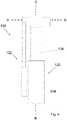
Figure 4 shows a side view of the thruster and the actuator assembly ofFigure 2 ; -
Figure 5 shows a front view of the thruster and the actuator assembly ofFigure 2 ; -
Figure 6 shows a part of an underwater vessel having the thruster and the actuator assembly stowed in the body; -
Figure 7 shows the thruster deployed in a first configuration; -
Figure 8 shows the thruster deployed in a second configuration; and -
Figure 9 shows the underwater vessel ofFigure 1 having a control system. - Referring to
Figure 1 , anunderwater vessel 100 is shown. Here, the underwater vessel is asubmarine 100. Thesubmarine 100 comprises abody 110. Thesubmarine 100 comprises athruster 120 operable to produce thrust. Thethruster 120 is deployable from thebody 110. Anactuator assembly 130 is connected to thethruster 120 and is operable to deploy thethruster 120. Theactuator assembly 130 is operable to deploy thethruster 120 in a first configuration in which thethruster 120 is oriented to produce a thrust having a vertical component when thethruster 120 is operated. - In the embodiment illustrated in
Figure 1 , thesubmarine 100 comprises fourthrusters 120. Twothrusters 120 are provided proximal the fore of thesubmarine 100, one either side of thebody 110. Two thrusters are provided proximal the aft of thesubmarine 100, one either side of thebody 110. Furthermore, the submarine comprises fouractuator assemblies 130, oneactuator assembly 130 associated with eachthruster 120. Of course, it will be understood by the skilled person that thesubmarine 100 may comprise a single actuator assembly operable to deploy each of a plurality of thrusters (in this case, the four thrusters 120). Eachthruster 120 is substantially identical in structure and operation. In this exemplary embodiment, eachthruster 120 is independently operable. Eachactuator assembly 130 is substantially identical in structure and operation, apart from appropriate modifications in directions of deployment and stowing, as will be appreciated by the skilled person from the description provided herein. - Referring to
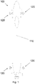
Figures 2 to 5 , athruster 120 and anactuator assembly 130 are shown. - The
thruster 120 is a rim-driven thruster (RDT). TheRDT 120 is absent a hub for the transmission of driving torque. TheRDT 120 comprises a plurality ofblades 122. Theblades 122 are mounted on a ring (not shown). The ring functions as the rotor of an electric motor. The ring is surrounded by a stator, which is correspondingly ring shaped, and creates the desired torque. The stator and ring are housed in anannular housing 124. RDTs have a small spatial profile, thereby reducing the volume necessary in which to stow theRDT 120 within thebody 110 of thesubmarine 100. Furthermore, since the rotor is electromagnetically driven, no shaft and no gearbox is needed, which reduces the weight of thethruster 120. In this way, deployment of thethruster 120, which involves movement of thethruster 120, is made easier. - The
actuator assembly 130 comprises astructure 132 having anarm 134 connected to thethruster 120. Theactuator assembly 130 further comprises two rotary actuators (not shown) housed within thestructure 132. A first one of the rotary actuators is operable to rotate thearm 134 by 90 degrees about a first axis A-A. The first axis A-A is perpendicular to the longitudinal axis of thearm 134. A second one of the rotary actuators is operable to rotate thearm 132 by 90 degrees about a second axis B-B. The second axis B-B is parallel to the longitudinal axis of thearm 134. - Referring to
Figures 6 to 8 , rear end views of the port side (that is, lefthand side) of thebody 110 of thesubmarine 100 are shown. InFigures 6 to 8 , the port side aftthruster 120 is shown. - Referring to
Figure 6 , thethruster 120 is shown stowed within thebody 110. In this stowed configuration, the plane of the thruster 120 - that is, the plane perpendicular to the direction of thrust when thethruster 120 is operated - is perpendicular to the length of thebody 110 of thesubmarine 100. In this example, thethruster 120 is stowed completely within thebody 110, with no part of thethruster 120 projecting from thebody 110. In this way, hydrodynamic properties of thesubmarine 100 are optimised when thethruster 120 is not deployed. Furthermore, platform performance is improved. - Referring to
Figure 7 , thethruster 120 is shown deployed in a first configuration in which thethruster 120 is oriented to produce a thrust having a vertical component when thethruster 120 is operated. In this exemplary embodiment, thethruster 120 is oriented to produce a vertical thrust. Here, the plane of thethruster 120 is parallel to the width of thebody 110 of thesubmarine 100. In this way, thethruster 120 is operable to produce a vertical thrust which allows thesubmarine 100 to maintain a constant depth or height above the seabed. In this way, thesubmarine 100 can hover in the water. - Movement of the
thruster 120 from the stowed configuration to the first configuration is performed by operating theactuator assembly 130 to rotate thearm 134 by 90 degrees about the first axis A-A. In this way, thethruster 120 is moved to swing out away from thebody 110. In combination with this first rotation,actuator assembly 130 is operated to rotate thearm 134 by 90 degrees about the second axis B-B. In this way, thethruster 120 is moved to be oriented with the plane of thethruster 120 being horizontal. In this way, theactuator assembly 130 is operable to deploy thethruster 120 in the first configuration. - Referring to
Figure 8 , thethruster 120 is shown deployed in a second configuration in which the thruster is oriented to produce a thrust having a horizontal component when thethruster 120 is operated. In this exemplary embodiment, thethruster 120 is oriented to produce a horizontal thrust. Here, the plane of thethruster 120 is perpendicular to the length of thebody 110. In this way, thethruster 120 is operable to produce a horizontal thrust which allows thesubmarine 100 to be propelled through the water. Theactuator assembly 130 is operable to deploy thethruster 120 in the second configuration in the event of failure of a primary propulsion system of thesubmarine 100, thereby to provide a secondary propulsion system. In this way, redundancy is incorporated into thesubmarine 100. In this exemplary embodiment, theactuator assembly 130 is operable to deploy theaft thrusters 120, on both the port and starboard side, in the second configuration in the event of failure of a primary propulsion system of thesubmarine 100. In other exemplary embodiments, one or more pairs of thrusters, including port side thrusters, starboard side thrusters or both pairs of fore and aft thrusters, may be deployed and operated in the event of failure of a primary propulsion system. - Movement of the
thruster 120 from the first configuration to the second configuration is performed by operating theactuator assembly 130 to rotate thearm 134 by 90 degrees about the second axis B-B. Movement of thethruster 120 from the stowed configuration to the second configuration is performed by operating theactuator assembly 130 to rotate thearm 134 by 90 degrees about the first axis A-A. In this way, theactuator assembly 130 is operable to deploy thethruster 120 in the second configuration. - It will be understood that movement from the second configuration to (or, back to) the first configuration is performed by operating the
actuator assembly 130 to rotate thearm 134 by 90 degrees about the second axis B-B. This rotation may include rotation in an opposite direction to the direction of rotation of thearm 134 from the first configuration to the second configuration. - When the
thruster 120 is not in use or no longer required, which may be when a primary propulsion system of thesubmarine 100 is to be used, theactuator assembly 130 is operated to move the thruster from the first or second configuration to the stowed configuration. - Of course, the
thruster 120 is repeatedly movable between the stowed configuration, first configuration and second configuration. Such movement of thethrusters 120 may otherwise be known as a vectorable thruster. - Referring to
Figure 9 , thesubmarine 100 comprises acontrol system 200. The control system is arranged to control operation of thethrusters 120. In one exemplary embodiment, the control system is arranged to control operation of theactuator assembly 130. In this way, the control system is arranged to control deployment of thethrusters 120. - Control of operation the
thrusters 120 is based on an operating condition of thesubmarine 100. The operating condition includes one or more of: position (including current or desired position), depth, weight, buoyancy, attitude, stability, centre of mass, centre of buoyancy, centre of gravity, and the like. Thecontrol system 200 is arranged to receive information relating to the operating condition from sensors provided on thesubmarine 100. Thecontrol system 200 is arranged to control operation of thethrusters 120 to maintain a substantially constant operating condition. In one exemplary embodiment, thecontrol system 200 is arranged to control operation of thethrusters 120 to maintain a constant depth, or height above the seabed. That is, thecontrol system 200 controls thethrusters 120 to cause thesubmarine 100 to hover at a constant depth. In doing so, thecontrol system 200 can also account for environmental conditions, including water temperature, water speed, density, and the like. - In one mode of operation, the
control system 200 controls theactuator assembly 130 to deploy thethrusters 120 in the first configuration, thereby to provide a vertical thrust component, and control operation of thethrusters 120 based on the desired depth which is desired to maintain. As mentioned above, thethrusters 120 are independently operable, and thecontrol system 200 is operable to control thethrusters 120 independently to maintain or obtain the operating condition. Independent operation of thethrusters 120 advantageously provides for maximum control of the stability, positioning and depth of thesubmarine 100. - In another mode of operation, the
control system 200 controls theactuator assembly 130 to deploy thethrusters 120 in the first and/or second configuration, and control operation of thethrusters 120 to maintain a desired level of stability of thesubmarine 100. In this way, complex systems, including pump systems, for maintaining stability of thesubmarine 100 may not be necessary, or can be supplemented by the present system, thereby reducing weight and complexity of thesubmarine 100. - It is to be understood that the singular forms "a," "an," and "the" include plural referents unless the context clearly dictates otherwise. The terms "front", "rear", "side", "upper", "lower", "over", "under", "inner", "outer" and like terms are used to refer to the apparatus and its components in the orientation in which it is illustrated, which is the orientation in which it is intended to be used but should not be taken as otherwise limiting. Like reference numerals are used to denote like features throughout the figures, which are not to scale.
Claims (15)
- An underwater vessel comprising:a body;a thruster operable to produce thrust, wherein the thruster is deployable from the body;an actuator assembly connected to the thruster and operable to deploy the thruster,wherein the actuator assembly is operable to deploy the thruster in a first configuration in which the thruster is oriented to produce a thrust having a vertical component when the thruster is operated.
- An underwater vessel according to claim 1 wherein the actuator assembly is operable to deploy the thruster by rotation about a first axis.
- An underwater vessel according to claim 1 or claim 2 wherein the thruster is stowable in the body, preferably stowable completely within the body.
- An underwater vessel according to claim 3 wherein the actuator assembly is operable to stow the thruster.
- An underwater vessel according to any one of the preceding claims wherein the actuator assembly is operable to deploy the thruster in a second configuration in which the thruster is oriented to produce a thrust having a horizontal component when the thruster is operated.
- An underwater vessel according to claim 5 wherein the actuator assembly is operable to move the thruster from the first configuration to the second configuration.
- An underwater vessel according to claim 5 or claim 6 wherein the actuator assembly is operable to move the thruster from the first configuration to second configuration by rotation about a second axis.
- An underwater vessel according to any of claims 5 to 7 wherein the actuator assembly is operable to deploy the thruster in the second configuration in the event of failure of a primary propulsion system of the submarine, thereby to provide a secondary propulsion system.
- An underwater vessel according to any one of the preceding claims comprising a control system arranged to control operation of the thruster based on an operating condition of the vessel.
- An underwater vessel according to claim 9 wherein the control system is arranged to control operation of the thruster to maintain a substantially constant operating condition.
- An underwater vessel according to claim 9 or claim 10 wherein the control system is arranged to:control the actuator assembly to deploy the thruster in the first configuration; andcontrol operation of the thruster based on an operating condition of the vessel, preferably to maintain a substantially constant operating condition.
- An underwater vessel according to any one of the preceding claims wherein the thruster comprises a rim driven thruster.
- An underwater vessel according to any one of the preceding claims comprising a plurality of thrusters, preferably four thrusters.
- An underwater vessel according to claim 13 wherein the thrusters are independently operable.
- An underwater vessel according to any one of the preceding claims wherein the underwater vessel is a submarine
Priority Applications (5)
| Application Number | Priority Date | Filing Date | Title |
|---|---|---|---|
| EP21275069.9A EP4098545A1 (en) | 2021-06-02 | 2021-06-02 | Underwater vessel |
| EP22726503.0A EP4347380A1 (en) | 2021-06-02 | 2022-05-23 | Underwater vessel |
| US18/566,155 US20240246650A1 (en) | 2021-06-02 | 2022-05-23 | Underwater vessel |
| AU2022286691A AU2022286691A1 (en) | 2021-06-02 | 2022-05-23 | Underwater vessel |
| PCT/GB2022/051293 WO2022254180A1 (en) | 2021-06-02 | 2022-05-23 | Underwater vessel |
Applications Claiming Priority (1)
| Application Number | Priority Date | Filing Date | Title |
|---|---|---|---|
| EP21275069.9A EP4098545A1 (en) | 2021-06-02 | 2021-06-02 | Underwater vessel |
Publications (1)
| Publication Number | Publication Date |
|---|---|
| EP4098545A1 true EP4098545A1 (en) | 2022-12-07 |
Family
ID=76269680
Family Applications (1)
| Application Number | Title | Priority Date | Filing Date |
|---|---|---|---|
| EP21275069.9A Pending EP4098545A1 (en) | 2021-06-02 | 2021-06-02 | Underwater vessel |
Country Status (1)
| Country | Link |
|---|---|
| EP (1) | EP4098545A1 (en) |
Citations (4)
| Publication number | Priority date | Publication date | Assignee | Title |
|---|---|---|---|---|
| US2806441A (en) * | 1952-05-15 | 1957-09-17 | Jr Harry H Hoke | Apparatus for stabilizing and maneuvering submarines |
| FR2742120A1 (en) * | 1995-12-08 | 1997-06-13 | Eca | Submarine vessel with propeller units mounted on projecting arms |
| US20020178990A1 (en) * | 2001-06-04 | 2002-12-05 | Mcbride Mark W. | Propulsion of underwater vehicles using differential and vectored thrust |
| EP2246252A2 (en) * | 2009-04-30 | 2010-11-03 | Howaldtswerke-Deutsche Werft GmbH | Submarine |
-
2021
- 2021-06-02 EP EP21275069.9A patent/EP4098545A1/en active Pending
Patent Citations (4)
| Publication number | Priority date | Publication date | Assignee | Title |
|---|---|---|---|---|
| US2806441A (en) * | 1952-05-15 | 1957-09-17 | Jr Harry H Hoke | Apparatus for stabilizing and maneuvering submarines |
| FR2742120A1 (en) * | 1995-12-08 | 1997-06-13 | Eca | Submarine vessel with propeller units mounted on projecting arms |
| US20020178990A1 (en) * | 2001-06-04 | 2002-12-05 | Mcbride Mark W. | Propulsion of underwater vehicles using differential and vectored thrust |
| EP2246252A2 (en) * | 2009-04-30 | 2010-11-03 | Howaldtswerke-Deutsche Werft GmbH | Submarine |
Similar Documents
| Publication | Publication Date | Title |
|---|---|---|
| JP2017197182A (en) | High speed surface boats and submersibles | |
| US9403579B2 (en) | Fleet protection attack craft | |
| US9555859B2 (en) | Fleet protection attack craft and underwater vehicles | |
| EP1329379B1 (en) | Ship propulsion and operating method therefor | |
| US5028210A (en) | Propeller unit with controlled cyclic and collective blade pitch | |
| US5758592A (en) | Undersea vehicle propulsion and attitude control system | |
| US5505155A (en) | Submarine propulsion system | |
| US20240246650A1 (en) | Underwater vessel | |
| GB2607313A (en) | Underwater vessel | |
| US3356055A (en) | Self-propelled diving chamber | |
| EP1970302A1 (en) | Oscillating hydrofoil propulsion and steering system | |
| WO2025185249A1 (en) | Reconfigurable underwater vehicle capable of long-range cruise and underwater interaction operation | |
| EP2987719B1 (en) | A vessel comprising a propulsion unit | |
| EP4731504A1 (en) | Semi-submersible marine vehicle useful in bad weather, which operates remotely | |
| CN108973559A (en) | A kind of empty amphibious five body constituents unmanned boat of water | |
| JP7733892B2 (en) | Vector control assembly for submersible vehicles. | |
| US11554841B1 (en) | Fluid medium vehicle | |
| Humphrey et al. | Design and fabrication of a collective and cyclic pitch propeller | |
| KR20200114063A (en) | Thruster for vessel and vessel including the same | |
| EP2841335B1 (en) | Aquatic rescue vehicle | |
| ES2916299B2 (en) | Surface and underwater navigation unmanned vessel | |
| JP2025160959A (en) | Submersible hydrofoil vessel and method of surfacing and submerging a submersible hydrofoil vessel | |
| WO2021225654A2 (en) | Amphibious aircraft taxiing and docking systems |
Legal Events
| Date | Code | Title | Description |
|---|---|---|---|
| PUAI | Public reference made under article 153(3) epc to a published international application that has entered the european phase |
Free format text: ORIGINAL CODE: 0009012 |
|
| STAA | Information on the status of an ep patent application or granted ep patent |
Free format text: STATUS: THE APPLICATION HAS BEEN PUBLISHED |
|
| AK | Designated contracting states |
Kind code of ref document: A1 Designated state(s): AL AT BE BG CH CY CZ DE DK EE ES FI FR GB GR HR HU IE IS IT LI LT LU LV MC MK MT NL NO PL PT RO RS SE SI SK SM TR |