EP4098496A1 - Device and method for monitoring at least one vehicle identification number - Google Patents
Device and method for monitoring at least one vehicle identification number Download PDFInfo
- Publication number
- EP4098496A1 EP4098496A1 EP21177612.5A EP21177612A EP4098496A1 EP 4098496 A1 EP4098496 A1 EP 4098496A1 EP 21177612 A EP21177612 A EP 21177612A EP 4098496 A1 EP4098496 A1 EP 4098496A1
- Authority
- EP
- European Patent Office
- Prior art keywords
- vehicle
- dongle
- backend server
- identification number
- monitoring
- Prior art date
- Legal status (The legal status is an assumption and is not a legal conclusion. Google has not performed a legal analysis and makes no representation as to the accuracy of the status listed.)
- Withdrawn
Links
- 238000012544 monitoring process Methods 0.000 title claims abstract description 44
- 238000000034 method Methods 0.000 title claims description 25
- 238000004891 communication Methods 0.000 claims abstract description 27
- 208000018777 Vulvar intraepithelial neoplasia Diseases 0.000 description 77
- 230000001413 cellular effect Effects 0.000 description 4
- 238000001514 detection method Methods 0.000 description 3
- 230000008520 organization Effects 0.000 description 2
- QVFWZNCVPCJQOP-UHFFFAOYSA-N chloralodol Chemical compound CC(O)(C)CC(C)OC(O)C(Cl)(Cl)Cl QVFWZNCVPCJQOP-UHFFFAOYSA-N 0.000 description 1
- 238000004590 computer program Methods 0.000 description 1
- 238000012790 confirmation Methods 0.000 description 1
Images

Classifications
-
- B—PERFORMING OPERATIONS; TRANSPORTING
- B60—VEHICLES IN GENERAL
- B60R—VEHICLES, VEHICLE FITTINGS, OR VEHICLE PARTS, NOT OTHERWISE PROVIDED FOR
- B60R25/00—Fittings or systems for preventing or indicating unauthorised use or theft of vehicles
- B60R25/30—Detection related to theft or to other events relevant to anti-theft systems
- B60R25/33—Detection related to theft or to other events relevant to anti-theft systems of global position, e.g. by providing GPS coordinates
-
- G—PHYSICS
- G07—CHECKING-DEVICES
- G07C—TIME OR ATTENDANCE REGISTERS; REGISTERING OR INDICATING THE WORKING OF MACHINES; GENERATING RANDOM NUMBERS; VOTING OR LOTTERY APPARATUS; ARRANGEMENTS, SYSTEMS OR APPARATUS FOR CHECKING NOT PROVIDED FOR ELSEWHERE
- G07C5/00—Registering or indicating the working of vehicles
- G07C5/008—Registering or indicating the working of vehicles communicating information to a remotely located station
Definitions
- the field of the disclosure is that of the access to vehicle's data.
- the disclosure relates to an electronic device configured for retrieving data from vehicles and sending it to a remote server.
- the disclosure can be of interest in any field wherein accessing to vehicle's data is of interest, e.g. for being able to track the position of a vehicle when it is stollen, or to monitor a car stock for a professional.
- dongles that can be connected to an on-board diagnostics, hereafter OBD, port of a vehicle can communicate with an external device for providing data read from the vehicle.
- OBD on-board diagnostics
- data can be for instance the status of the various vehicle sub-systems (real-time parameters, diagnostic trouble codes, engine status, etc.) following the OBD standards.
- the dongle can provide other data like the position of the vehicle in case e.g. a Global Positioning Specification, hereafter GPS, receiver is implemented in the vehicle.
- GPS Global Positioning Specification
- OBD ports of vehicles are well-known so that such dongle can be found easily in the vehicle. Consequently, in case a vehicle is stolen, a thief can find the dongle without much efforts and disconnect it from the vehicle. in that case, there is no more possibility to access to the vehicle's data or to know its position.
- a particular aspect of the present disclosure relates to a device for monitoring at least one vehicle identification number sent by a dongle connected to an on-board diagnostics, hereafter OBD, port of a vehicle.
- OBD on-board diagnostics
- the present disclosure proposes a new and inventive solution for securing the tracking of a vehicle, or the access to the data of such vehicle, the vehicle being identified by its vehicle identification number (also known as “chassis number” or “frame number”) as defined e.g. in the International Organization for Standardization, hereafter ISO, standards 3779 and 4030.
- vehicle identification number also known as "chassis number” or "frame number”
- ISO International Organization for Standardization
- the proposed device is battery powered and communicates wirelessly so that there is no need for an electrical wired connection to the vehicle. Accordingly, the device can be implemented in the vehicle in a hidden place so that it cannot be found easily e.g. in case the vehicle is s Heck. Even in such case, the data can thus still be accessed remotely from the vehicle through the communication with the backend server as long as the device is not discovered by the thief.
- the means for wirelessly communicating comprise a short-range communications transceiver for communicating with the at least one dongle. It can be e.g. a Bluetooth transceiver.
- the means for wirelessly communicating comprise a long-range communications transceiver for communicating with the backend server. It can be a transceiver according to a cellular network standard, e.g. a Third Generation Partnership Project, hereafter 3GPP, 2G, 3G, 4G or 5G cellular network.
- a cellular network standard e.g. a Third Generation Partnership Project, hereafter 3GPP, 2G, 3G, 4G or 5G cellular network.
- the device comprise a Global Navigation Satellite System receiver. It can be e.g. a Global Positioning Specification, hereafter GPS, a Galileo, a Glonass or a Beidou receiver.
- GPS Global Positioning Specification
- Galileo Galileo
- Glonass Glonass
- Beidou receiver Beidou receiver
- the device (according to any of the embodiments disclosed above) is implemented in a vehicle.
- the means for wirelessly communicating are configured for communicating with at least one dongle connected to an OBD port of the vehicle.
- the device is not electrically wired connected to the vehicle.
- the device can be implemented in the vehicle in a hidden place so that it cannot be found easily e.g. in case the vehicle is splin.
- Another aspect of the present disclosure relates to a vehicle comprising a device as disclosed above (according to any of the embodiments disclosed above).
- the device is not electrically wired connected to the vehicle.
- the means for wirelessly communicating are configured for communicating with at least one dongle connected to an OBD port of the vehicle.
- Another aspect of the present disclosure relates to a method for monitoring at least one vehicle identification number implemented by a device as disclosed above (according to any of the embodiments disclosed above).
- the method comprises:
- the monitoring is implemented responsive to receiving, by the device, a request sent by the backend server for discovering vehicle identification number.
- the device sends to the backend server the at least one vehicle identification number received, during the monitoring, from a dongle connected to an OBD port of a vehicle.
- the device sends to the backend server additional data received from the dongle during the monitoring.
- the additional data comprise data extracted from the vehicle providing e.g. status of the various vehicle sub-systems (real-time parameters, diagnostic trouble codes, engine status, etc.).
- the device receives back the vehicle identification number sent from the backend server for pairing the device to the vehicle.
- the device implements:
- the device implements sending an alarm to the backend server when the given vehicle identification number and the vehicle identification number are different vehicle identification numbers.
- the device sends an alarm when it has been found and removed from the vehicle corresponding to the given vehicle identification number.
- the device sends to the backend server additional data received from the dongle during the monitoring.
- the device implements, during the monitoring, establishing a dedicated communication link with the dongle for receiving the vehicle identification number and/or the additional data sent by said dongle.
- the device implements sending an alarm to the backend server responsive to detecting that the dedicated communication link is broken.
- the monitoring is implemented periodically.
- the device comprises a Global Navigation Satellite System receiver and sends to the backend server geolocation data provided by the Global Navigation Satellite System receiver.
- the position of the vehicle the device is implemented in can be tracked.
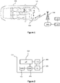
- FIG. 1 we describe a device 120 configured for monitoring a VIN sent by a dongle 110 connected to an OBD port of a vehicle 100 according to one embodiment of the present disclosure.
- An example of the structural blocks that can be implemented in the device 120 are further described in relation with Figure 2 .
- the device 120 comprises a battery 205 and is thus battery powered.
- the device 120 further comprises means 204 for wirelessly communicating with:
- the device 120 is configured for wirelessly communicating with any dongle connected to an OBD port of a corresponding vehicle, and not only with the dongle 110 connected to an OBD port of the vehicle 100. This holds as long as such dongle is within the range of the short-range communications transceiver of the means 204 for wirelessly communicating.
- the means 204 for wirelessly communicating comprise a transceiver according to long-range communications protocol.
- Such long-range communications maybe a cellular network standard for communicating with the backend server 150 through the base station 130. It can be e.g. a Third Generation Partnership Project, hereafter 3GPP, 2G, 3G, 4G or 5G cellular network.
- the transceiver for communicating with the backend server 150 implements another long-range communications standard, e.g. a narrowband standard dedicated to the internet of things (SigFox ® , LoRa ® , etc.).
- the device 120 is configured for monitoring the VIN of the vehicle 100 (or of the vehicles within the range of the short-range communications transceiver depending on the embodiments) and reporting it to the backend server 150.
- VIN is also known as "chassis number” or “frame number” as defined e.g. in the International Organization for Standardization, hereafter ISO, standards 3779 and 4030.
- the device 120 is configured for implementing some of the steps of the method described below in relation with Figures 3, 4 and 5 . Accordingly, in some embodiments, the device 120 reports to the backend server 150 additional data comprising data extracted from the vehicle 100 providing e.g. a status of the various vehicle sub-systems (real-time parameters, diagnostic trouble codes, engine status, etc.) or of the dongle 110 itself.
- additional data comprising data extracted from the vehicle 100 providing e.g. a status of the various vehicle sub-systems (real-time parameters, diagnostic trouble codes, engine status, etc.) or of the dongle 110 itself.
- the device 120 comprises a Global Navigation Satellite System, hereafter GNSS, receiver. It can be e.g. a Global Positioning Specification, hereafter GPS, a Galileo, a Glonass or a Beidou receiver. Accordingly, in some embodiments, the device 120 reports its position and/or corresponding geolocation data to the backend server 150.
- GNSS Global Navigation Satellite System
- the device 120 is battery powered and communicates wirelessly with the vehicle 100. Consequently, the device 120 is not electrically wired connected to the vehicle 100. Accordingly, the device 120 can be implemented in the vehicle in a hidden place so that it cannot be found easily e.g. in case the vehicle 100 is s Heck. Even in such case, the data can thus still be accessed remotely from the vehicle 100 through the communication with the backend server150 as long as the device 120 is not discovered by the thief.
- the backend server150 is further in communication (e.g. wireless or wired communication) with a terminal 160 (e.g. a smartphone, a computer, a tablet, etc.) so that a user can retrieve the data and/or control the device 120 by interacting with the terminal 160 as discussed below in relation with Figures 3, 4 and 5 .
- a terminal 160 e.g. a smartphone, a computer, a tablet, etc.
- the vehicle 100 is represented in the form of a car.
- the device 120 can be implemented in any vehicle identified by its VIN and that comprises an ODB port (e.g. a truck).
- the device 120 also comprises:
- the non-volatile memory 203 is a non-transitory computer-readable carrier medium. It stores executable program code instructions, which are executed by the processor 202 in order to enable implementation of some steps of the method described below (method for monitoring at least one VIN) in the various embodiment disclosed in relationship with below in relation with Figures 3, 4 and 5 .
- the aforementioned program code instructions are transferred from the non-volatile memory 203 to the volatile memory 201 so as to be executed by the processor 202.
- the volatile memory 201 likewise includes registers for storing the variables and parameters required for this execution.
- the steps of the method for monitoring at least one VIN may be implemented equally well:
- the disclosure is not limited to a purely software-based implementation, in the form of computer program instructions, but that it may also be implemented in hardware form or any form combining a hardware portion and a software portion.
- the device 120 is implemented in the vehicle 100.
- the device 120 is implemented in a distinct apparatus (e.g. a portable terminal) and is used to communicate with one (or more) dongle connected to a corresponding vehicle.
- the apparatus comprising the device 120 can be used as a tool e.g. for monitoring and/or retrieving data from various vehicles.
- Such method comprises steps implemented by the dongle 110, the device 120, the backend server150 and the terminal 160.
- the first use case is directed to the pairing of the device 120 with the VIN of the vehicle 100 the device 120 is implemented in.
- a step S300 the terminal 160 sends a request to the backend server 150 for discovering a VIN.
- the step S300 is implemented by the terminal 160 responsive to a user having selected or entered the VIN in an interface of the terminal 160.
- step S300 the backend server 150 receives the request for discovering the VIN sent by the terminal 160.
- a step S310 responsive to receiving the request for discovering the VIN sent by the terminal 160, the backend server 150 forwards the request (or sends another corresponding request for discovering the VIN) to the device 120.
- step S310 the device 120 receives the request for discovering the VIN sent by the backend server 150.
- a step S320 responsive to receiving the request for discovering the VIN sent by the backend server 150, the device 120 enters a monitoring phase until it detects the reception of a message from the dongle 110 carrying the VIN corresponding to the request.
- the monitoring phase can last for a predetermined duration at maximum so that if the VIN is not received within the predetermined duration, the device 120 ends the monitoring phase and sends an error message to the backend server 150.
- a step S340 the dongle 110 sends (or broadcasts as discussed below) a message carrying the VIN to the device 120.
- Such sending of the message may result of an action of the user on the dongle in a step S330.
- Such action can be e.g. pressing a dedicated button of the dongle 110 for having the dongle to broadcast the VIN of the vehicle 100.
- the dongle 110 broadcasts e.g. periodically (e.g. proactively) the VIN of the vehicle 100 in step S340.
- step S340 the device 120 receives correspondingly the message carrying the VIN sent by the dongle 110.
- a step S350 responsive to receiving the message carrying the VIN sent by the dongle 110, the device 120 forwards the message carrying the VIN (or sends another corresponding message carrying the VIN) to the backend server 150.
- step S350 the backend server 150 receives the message carrying the VIN sent by the device 120.
- a step S360 responsive to receiving the message carrying the VIN sent by the device 120, the backend server 150 forwards the message carrying the VIN (or sends another corresponding message carrying the VIN) to the terminal 160.
- step S360 the terminal 160 receives the message carrying the VIN sent by the backend server 150.
- a step S370 the user confirms that the VIN received by the terminal 160 corresponds to the vehicle the device 120 has to be paired with. For instance, the VIN received by the terminal 160 is displayed on a screen of the terminal 160. The user thus checks the VIN and confirms the pairing by acting correspondingly on the interface of the terminal 160.
- a step S380 responsive to the confirmation of the pairing by the user, the terminal 160 sends a request to the backend server 150 for pairing the device 120 and the vehicle 100 (or equivalently for pairing the device 120 and the VIN of the vehicle 100).
- request may comprise the VIN of the vehicle 100.
- step S380 the backend server 150 receives the request sent by the terminal 160 for pairing the device 120 and the vehicle 100.
- a step S390 responsive to receiving the request sent by the terminal 160 for pairing the device 120 and the vehicle 100 (or equivalently for pairing the device 120 and the VIN of the vehicle 100), the backend server 150 forwards the request (or sends another request for pairing the device 120 and the vehicle 100) to the device 120.
- request may comprise the VIN of the vehicle 100.
- step S390 the device 120 receives the request sent by the backend server 150 for pairing the device 120 and the vehicle 100.
- the device 120 is associated with the VIN of the vehicle 100. For instance, this allows having the device 120 to monitor for VIN sent by dongles, whether upon request from the backend server 150 or periodically (e.g. proactively), and to check that the received VIN(s) match the VIN of the vehicle 100. This allows detecting for instance that the device 120 has been extracted from the vehicle 100, e.g. by a thief. Such use case is discussed more deeply below in relation with Figure 4 .
- the steps S300 to S380 are not implemented and only the step S390 is implemented for pairing the device 120 and the vehicle 100 based on the receiving, by the device 120, of a request sent by the backend server 150.
- the step S390 is not implemented and the pairing of the device 120 and the vehicle 100 is done only at the level of the backend server 150.
- the device 100 sends back the monitored VIN(s) to the backend server 150. This allows the backend server 150 to check that the received VIN(s) match the VIN of the vehicle 100 the device 120 is paired with and thus that the device 120 has not been extracted from the vehicle 100.
- the dongle 110 sends (or broadcasts as discussed below) additional data to the device 120.
- additional data may comprise e.g. data extracted from the vehicle 100 providing e.g. status of the various vehicle sub-systems (real-time parameters, diagnostic trouble codes, engine status, etc.).
- additional data may also comprise data relating to the status of the dongle 110, e.g. data representative of the correct connection of the dongle 110 to the ODB port of the vehicle 100.
- the dongle 110 may report an alert to the device 120 as additional data.
- Such alert may be forwarded as additional data by the device 120 to the backend server 150 when the device 120 does not detect any more the dongle 110 within the range of the means 204 for wirelessly communicating with dongles.
- the additional data may be forwarded by the device 120 in addition to the VIN up to the backend server 150 (during step S350), and then up to the terminal 160 (step S360), e.g. for display to the user.
- the VIN and/or the additional data are broadcasted by the dongle 110 during step S340 (e.g. following a multicast scheme). In that case, the device 120 receives corresponding broadcasted messages sent by the dongle 110. In other embodiments, the device 120 establishes a dedicated communication link (e.g. following a unicast scheme) with the dongle 110. In that case, the device 120 receives corresponding dedicated messages (comprising e.g. a corresponding VIN and/or additional data) sent by the dongle 110. Such dedicated communication link may be secured, e.g. using an encryption scheme for such link.
- the device 120 may be configured for detecting a break (or drop) in such communication link with the dongle 110.
- Such break may e.g. be representative that a thief has disconnected the dongle 110 from the OBD port of the vehicle 100.
- the device 120 may send an alarm to the backend server 150 (e.g. during a step S420 as described below in relation with Figure 4 ) responsive to the detection that the communication link is broken.
- the second use case is directed for instance to the checking that the device 120 is still implemented in the vehicle 100.
- Such checking can be implemented after the pairing of the device 120 with the vehicle 100 as disclosed above in relation with Figure 3 or not.
- the device 120 receives from the backend server 150 a VIN, e.g. the VIN of the vehicle 100.
- the VIN may be received through a request sent by the backend server 150 for pairing the device 120 and the vehicle 100.
- the step S400 may be identical to the step S390 of Figure 3 .
- the VIN may be received through a dedicated request sent by the backend server 150.
- the device 120 After receiving the VIN, the device 120 enters a monitoring phase until it detects the reception of a message carrying a VIN sent from a dongle connected to an ODB port of a vehicle (steps S320 and S340 discussed above in relation with Figure 3 ).
- a step S410 the device 120 verifies that the VIN sent by a dongle matches the VIN received from the backend server 150 during step S400, e.g. by comparison of the VINs. In case the VIN received from the dongle is different than the VIN received from the backend server 150, the device 120 generates an alarm.
- the VIN received from the backend server 150 is the VIN of the vehicle 100 the device 120 is paired with, such alarm may be representative of the fact that the device 120 has been extracted from the vehicle 100, e.g. by a thief.
- a step S420 the device 120 sends a message carrying the alarm to the backend server 150.
- step S420 the backend server 150 receives the message carrying the alarm sent by the device 120.
- a step S430 responsive to receiving the message carrying the alarm sent by the device 120, the backend server 150 forwards the message carrying the alarm (or sends another corresponding message carrying the alarm) to the terminal 160.
- step S430 the terminal 160 receives the message carrying the alarm sent by the backend server 150.
- the user is thus informed, e.g. by a display on a screen of the terminal 160, that a problem occurred with the device 120 (e.g. a theft).
- a problem occurred with the device 120 (e.g. a theft).
- step S340 additional data are received from monitored dongles.
- additional data may be forwarded by the device 120, in addition to the alarm, up to the backend server 150 (during step S420), and then up to the terminal 160 (step S430), e.g. for display to the user.
- the third use case is directed for instance to the detection of nearby vehicles through the monitoring of their VINs. Such detection can be implemented whereas the device 120 is already paired with a vehicle according to the first use case disclosed above in relation with Figure 3 or not.
- the device 120 enters a monitoring phase (step S320 discussed above in relation with Figure 3 ).
- a monitoring phase may be entered upon reception of a corresponding request from the backend server 150, or may be a default state of the device 120 unless otherwise instructed by the backend server 150 (i.e. a proactive monitoring).
- each time during the monitoring the device 120 receives a message carrying a VIN sent from a dongle connected to an ODB port of a corresponding vehicle (step S340 discussed above in relation with Figure 3 ), the device 120 sends a message carrying the VIN to the backend server 150.
- step S500 the backend server 150 receives the message sent by the device 120 carrying the VIN.
- a step S510 responsive to receiving the message sent by the device 120 carrying the VIN, the backend server 150 forwards the message carrying the VIN (or sends another corresponding message carrying the VIN) to the terminal 160.
- step S510 the terminal 160 receives the message carrying the VIN sent by the backend server 150.
- the user is thus informed, e.g. by a display on the screen of the terminal 160, of the list of the VINs of vehicles within the range of the means 204 for wirelessly communicating with dongles.
- step S340 additional data are received from monitored dongles.
- additional data may be forwarded by the device 120, in addition to the VINs, up to the backend server 150 (during step S500), and then up to the terminal 160 (step S510), e.g. for display to the user.
- the additional data reported by the device 120 may comprise the position of the device 120 and/or corresponding geolocation data.
- the position and/or corresponding geolocation data may be forwarded by the backend server 150 to the terminal 160 (steps S430 or S510).
- the device 120 thus implements the monitoring of at least one VIN sent by a dongle connected to an OBD port of a vehicle. Such monitoring is responsive or not of the receiving, by the device 120, of a request sent by the backend server 150 for discovering VIN.
Landscapes
- Physics & Mathematics (AREA)
- General Physics & Mathematics (AREA)
- Engineering & Computer Science (AREA)
- Radar, Positioning & Navigation (AREA)
- Remote Sensing (AREA)
- Mechanical Engineering (AREA)
- Mobile Radio Communication Systems (AREA)
- Electric Propulsion And Braking For Vehicles (AREA)
- Alarm Systems (AREA)
Abstract
Device (120) for monitoring at least one vehicle identification number sent by a dongle connected to an on-board diagnostics, hereafter OBD, port of a vehicle. Such device is battery powered and comprises means for wirelessly communicating with:
- at least one dongle (110) connected to an OBD port of a corresponding vehicle (100); and
- a backend server (150) through a communication network (140).
- at least one dongle (110) connected to an OBD port of a corresponding vehicle (100); and
- a backend server (150) through a communication network (140).
Description
- The field of the disclosure is that of the access to vehicle's data.
- More specifically, the disclosure relates to an electronic device configured for retrieving data from vehicles and sending it to a remote server.
- The disclosure can be of interest in any field wherein accessing to vehicle's data is of interest, e.g. for being able to track the position of a vehicle when it is stollen, or to monitor a car stock for a professional.
- Electronic systems for accessing to vehicle's data are known. For instance, dongles that can be connected to an on-board diagnostics, hereafter OBD, port of a vehicle can communicate with an external device for providing data read from the vehicle. Such data can be for instance the status of the various vehicle sub-systems (real-time parameters, diagnostic trouble codes, engine status, etc.) following the OBD standards. Alternatively, the dongle can provide other data like the position of the vehicle in case e.g. a Global Positioning Specification, hereafter GPS, receiver is implemented in the vehicle.
- However, OBD ports of vehicles are well-known so that such dongle can be found easily in the vehicle. Consequently, in case a vehicle is stolen, a thief can find the dongle without much efforts and disconnect it from the vehicle. in that case, there is no more possibility to access to the vehicle's data or to know its position.
- There is thus a need for a solution for securing the access to the data of a vehicle or the tracking of the vehicle, e.g. even when the vehicle is stollen.
- A particular aspect of the present disclosure relates to a device for monitoring at least one vehicle identification number sent by a dongle connected to an on-board diagnostics, hereafter OBD, port of a vehicle. Such device is battery powered and comprises means for wirelessly communicating with:
- at least one dongle connected to an OBD port of a corresponding vehicle; and
- a backend server through a communication network.
- Thus, the present disclosure proposes a new and inventive solution for securing the tracking of a vehicle, or the access to the data of such vehicle, the vehicle being identified by its vehicle identification number (also known as "chassis number" or "frame number") as defined e.g. in the International Organization for Standardization, hereafter ISO, standards 3779 and 4030.
- More particularly, the proposed device is battery powered and communicates wirelessly so that there is no need for an electrical wired connection to the vehicle. Accordingly, the device can be implemented in the vehicle in a hidden place so that it cannot be found easily e.g. in case the vehicle is stollen. Even in such case, the data can thus still be accessed remotely from the vehicle through the communication with the backend server as long as the device is not discovered by the thief.
- In some embodiments, the means for wirelessly communicating comprise a short-range communications transceiver for communicating with the at least one dongle. It can be e.g. a Bluetooth transceiver.
- In some embodiments, the means for wirelessly communicating comprise a long-range communications transceiver for communicating with the backend server. It can be a transceiver according to a cellular network standard, e.g. a Third Generation Partnership Project, hereafter 3GPP, 2G, 3G, 4G or 5G cellular network.
- In some embodiments, the device comprise a Global Navigation Satellite System receiver. It can be e.g. a Global Positioning Specification, hereafter GPS, a Galileo, a Glonass or a Beidou receiver.
- In some embodiments, the device (according to any of the embodiments disclosed above) is implemented in a vehicle. The means for wirelessly communicating are configured for communicating with at least one dongle connected to an OBD port of the vehicle.
- In some embodiments, the device is not electrically wired connected to the vehicle.
- Thus, the device can be implemented in the vehicle in a hidden place so that it cannot be found easily e.g. in case the vehicle is stollen.
- Another aspect of the present disclosure relates to a vehicle comprising a device as disclosed above (according to any of the embodiments disclosed above). The device is not electrically wired connected to the vehicle. The means for wirelessly communicating are configured for communicating with at least one dongle connected to an OBD port of the vehicle.
- Another aspect of the present disclosure relates to a method for monitoring at least one vehicle identification number implemented by a device as disclosed above (according to any of the embodiments disclosed above). The method comprises:
- monitoring the at least one vehicle identification number sent by a dongle connected to an OBD port of a vehicle.
- In some embodiments, the monitoring is implemented responsive to receiving, by the device, a request sent by the backend server for discovering vehicle identification number.
- In some embodiments, the device sends to the backend server the at least one vehicle identification number received, during the monitoring, from a dongle connected to an OBD port of a vehicle.
- In some embodiments, the device sends to the backend server additional data received from the dongle during the monitoring.
- For instance, the additional data comprise data extracted from the vehicle providing e.g. status of the various vehicle sub-systems (real-time parameters, diagnostic trouble codes, engine status, etc.).
- In some embodiments, the device receives back the vehicle identification number sent from the backend server for pairing the device to the vehicle.
- In some embodiments, the device implements:
- receiving a given vehicle identification number sent from the backend server;
- receiving, during the monitoring, a vehicle identification number from a dongle connected to an OBD port of a corresponding vehicle; and
- comparing the given vehicle identification number and the vehicle identification number.
- In some embodiments, the device implements sending an alarm to the backend server when the given vehicle identification number and the vehicle identification number are different vehicle identification numbers.
- Thus, the device sends an alarm when it has been found and removed from the vehicle corresponding to the given vehicle identification number.
- In some embodiments, the device sends to the backend server additional data received from the dongle during the monitoring.
- In some embodiments, the device implements, during the monitoring, establishing a dedicated communication link with the dongle for receiving the vehicle identification number and/or the additional data sent by said dongle.
- In some embodiments, the device implements sending an alarm to the backend server responsive to detecting that the dedicated communication link is broken.
- In some embodiments, the monitoring is implemented periodically.
- In some embodiments, the device comprises a Global Navigation Satellite System receiver and sends to the backend server geolocation data provided by the Global Navigation Satellite System receiver.
- Thus, the position of the vehicle the device is implemented in can be tracked.
- Other features and advantages of embodiments shall appear from the following description, given by way of indicative and non-exhaustive examples and from the appended drawings, of which:
-
Figure 1 illustrates a device implemented in a vehicle and configured for monitoring the vehicle identification number, hereafter VIN, sent by a dongle connected to an OBD port of the vehicle according to one embodiment of the present disclosure; -
Figure 2 illustrates an example of the structural blocks that can be implemented in the device ofFigure 1 ; -
Figure 3 illustrates a method for monitoring at least one VIN, implemented by the entities ofFigure 1 , in the context of a first use case; -
Figure 4 illustrates the method for monitoring at least one VIN in the context of a second use case; -
Figure 5 illustrates the method for monitoring at least one VIN in the context of a third use case. - In all of the Figures of the present document, the same numerical reference signs designate similar elements and steps.
- Referring now to
Figure 1 , we describe adevice 120 configured for monitoring a VIN sent by adongle 110 connected to an OBD port of avehicle 100 according to one embodiment of the present disclosure. An example of the structural blocks that can be implemented in thedevice 120 are further described in relation withFigure 2 . - The
device 120 comprises abattery 205 and is thus battery powered. Thedevice 120 further comprisesmeans 204 for wirelessly communicating with: - the
dongle 110 connected to an OBD port of thevehicle 100; and - a
backend server 150 through thecommunication network 140. - In some embodiments, the
device 120 is configured for wirelessly communicating with any dongle connected to an OBD port of a corresponding vehicle, and not only with thedongle 110 connected to an OBD port of thevehicle 100. This holds as long as such dongle is within the range of the short-range communications transceiver of themeans 204 for wirelessly communicating. - Back to
Figures 1 and 2 , themeans 204 for wirelessly communicating comprise a transceiver according to long-range communications protocol. Such long-range communications maybe a cellular network standard for communicating with thebackend server 150 through thebase station 130. It can be e.g. a Third Generation Partnership Project, hereafter 3GPP, 2G, 3G, 4G or 5G cellular network. In other embodiments, the transceiver for communicating with thebackend server 150 implements another long-range communications standard, e.g. a narrowband standard dedicated to the internet of things (SigFox®, LoRa®, etc.). - Back to
Figures 1 and 2 , thedevice 120 is configured for monitoring the VIN of the vehicle 100 (or of the vehicles within the range of the short-range communications transceiver depending on the embodiments) and reporting it to thebackend server 150. Such VIN is also known as "chassis number" or "frame number" as defined e.g. in the International Organization for Standardization, hereafter ISO, standards 3779 and 4030. - More generally, the
device 120 is configured for implementing some of the steps of the method described below in relation withFigures 3, 4 and 5 . Accordingly, in some embodiments, thedevice 120 reports to thebackend server 150 additional data comprising data extracted from thevehicle 100 providing e.g. a status of the various vehicle sub-systems (real-time parameters, diagnostic trouble codes, engine status, etc.) or of thedongle 110 itself. - In some embodiments, the
device 120 comprises a Global Navigation Satellite System, hereafter GNSS, receiver. It can be e.g. a Global Positioning Specification, hereafter GPS, a Galileo, a Glonass or a Beidou receiver. Accordingly, in some embodiments, thedevice 120 reports its position and/or corresponding geolocation data to thebackend server 150. - Back to
Figures 1 and 2 , as discussed above, thedevice 120 is battery powered and communicates wirelessly with thevehicle 100. Consequently, thedevice 120 is not electrically wired connected to thevehicle 100. Accordingly, thedevice 120 can be implemented in the vehicle in a hidden place so that it cannot be found easily e.g. in case thevehicle 100 is stollen. Even in such case, the data can thus still be accessed remotely from thevehicle 100 through the communication with the backend server150 as long as thedevice 120 is not discovered by the thief. The backend server150 is further in communication (e.g. wireless or wired communication) with a terminal 160 (e.g. a smartphone, a computer, a tablet, etc.) so that a user can retrieve the data and/or control thedevice 120 by interacting with the terminal 160 as discussed below in relation withFigures 3, 4 and 5 . - In
Figure 1 , thevehicle 100 is represented in the form of a car. However, thedevice 120 can be implemented in any vehicle identified by its VIN and that comprises an ODB port (e.g. a truck). - In order to be able to implement the method discussed below in relation with
Figures 3, 4 and 5 (according to any of the embodiments disclosed below), in some embodiments thedevice 120 also comprises: - a non-volatile memory 203 (e.g. a read-only memory (ROM), a hard disk, a flash memory, etc.);
- a volatile memory 201 (e.g. a random-access memory or RAM) and a
processor 202. - The
non-volatile memory 203 is a non-transitory computer-readable carrier medium. It stores executable program code instructions, which are executed by theprocessor 202 in order to enable implementation of some steps of the method described below (method for monitoring at least one VIN) in the various embodiment disclosed in relationship with below in relation withFigures 3, 4 and 5 . - Upon initialization, the aforementioned program code instructions are transferred from the
non-volatile memory 203 to thevolatile memory 201 so as to be executed by theprocessor 202. Thevolatile memory 201 likewise includes registers for storing the variables and parameters required for this execution. - The steps of the method for monitoring at least one VIN may be implemented equally well:
- by the execution of a set of program code instructions executed by a reprogrammable computing machine such as a PC type apparatus, a DSP (digital signal processor) or a microcontroller. This program code instructions can be stored in a non-transitory computer-readable carrier medium that is detachable (for example a CD-ROM, a DVD-ROM, a USB key) or non-detachable; or
- by a dedicated machine or component, such as an FPGA (Field Programmable Gate Array), an ASIC (Application-Specific Integrated Circuit) or any dedicated hardware component.
- In other words, the disclosure is not limited to a purely software-based implementation, in the form of computer program instructions, but that it may also be implemented in hardware form or any form combining a hardware portion and a software portion.
- In the embodiment of
Figure 1 , thedevice 120 is implemented in thevehicle 100. However, in other embodiments, thedevice 120 is implemented in a distinct apparatus (e.g. a portable terminal) and is used to communicate with one (or more) dongle connected to a corresponding vehicle. In such implementations, the apparatus comprising thedevice 120 can be used as a tool e.g. for monitoring and/or retrieving data from various vehicles. - Referring now to
Figure 3 , we describe a method for monitoring at least one VIN in the context of a first use case. Such method comprises steps implemented by thedongle 110, thedevice 120, the backend server150 and the terminal 160. - More particularly, the first use case is directed to the pairing of the
device 120 with the VIN of thevehicle 100 thedevice 120 is implemented in. - In that respect, in a step S300, the terminal 160 sends a request to the
backend server 150 for discovering a VIN. For instance, the step S300 is implemented by the terminal 160 responsive to a user having selected or entered the VIN in an interface of the terminal 160. - Correspondingly, in step S300, the
backend server 150 receives the request for discovering the VIN sent by theterminal 160. - In a step S310, responsive to receiving the request for discovering the VIN sent by the terminal 160, the
backend server 150 forwards the request (or sends another corresponding request for discovering the VIN) to thedevice 120. - Correspondingly, in step S310, the
device 120 receives the request for discovering the VIN sent by thebackend server 150. - In a step S320, responsive to receiving the request for discovering the VIN sent by the
backend server 150, thedevice 120 enters a monitoring phase until it detects the reception of a message from thedongle 110 carrying the VIN corresponding to the request. - In some embodiments, the monitoring phase can last for a predetermined duration at maximum so that if the VIN is not received within the predetermined duration, the
device 120 ends the monitoring phase and sends an error message to thebackend server 150. - In a step S340, the
dongle 110 sends (or broadcasts as discussed below) a message carrying the VIN to thedevice 120. Such sending of the message may result of an action of the user on the dongle in a step S330. Such action can be e.g. pressing a dedicated button of thedongle 110 for having the dongle to broadcast the VIN of thevehicle 100. In other embodiments, thedongle 110 broadcasts e.g. periodically (e.g. proactively) the VIN of thevehicle 100 in step S340. - Back to
figure 3 , in step S340, thedevice 120 receives correspondingly the message carrying the VIN sent by thedongle 110. - In a step S350, responsive to receiving the message carrying the VIN sent by the
dongle 110, thedevice 120 forwards the message carrying the VIN (or sends another corresponding message carrying the VIN) to thebackend server 150. - Correspondingly, in step S350, the
backend server 150 receives the message carrying the VIN sent by thedevice 120. - In a step S360, responsive to receiving the message carrying the VIN sent by the
device 120, thebackend server 150 forwards the message carrying the VIN (or sends another corresponding message carrying the VIN) to the terminal 160. - Correspondingly, in step S360, the terminal 160 receives the message carrying the VIN sent by the
backend server 150. - In a step S370, the user confirms that the VIN received by the terminal 160 corresponds to the vehicle the
device 120 has to be paired with. For instance, the VIN received by the terminal 160 is displayed on a screen of the terminal 160. The user thus checks the VIN and confirms the pairing by acting correspondingly on the interface of the terminal 160. - In a step S380, responsive to the confirmation of the pairing by the user, the terminal 160 sends a request to the
backend server 150 for pairing thedevice 120 and the vehicle 100 (or equivalently for pairing thedevice 120 and the VIN of the vehicle 100). Such request may comprise the VIN of thevehicle 100. - Correspondingly, in step S380, the
backend server 150 receives the request sent by the terminal 160 for pairing thedevice 120 and thevehicle 100. - In a step S390, responsive to receiving the request sent by the terminal 160 for pairing the
device 120 and the vehicle 100 (or equivalently for pairing thedevice 120 and the VIN of the vehicle 100), thebackend server 150 forwards the request (or sends another request for pairing thedevice 120 and the vehicle 100) to thedevice 120. Such request may comprise the VIN of thevehicle 100. - Correspondingly, in step S390, the
device 120 receives the request sent by thebackend server 150 for pairing thedevice 120 and thevehicle 100. - Thus, after the implementation of such pairing, the
device 120 is associated with the VIN of thevehicle 100. For instance, this allows having thedevice 120 to monitor for VIN sent by dongles, whether upon request from thebackend server 150 or periodically (e.g. proactively), and to check that the received VIN(s) match the VIN of thevehicle 100. This allows detecting for instance that thedevice 120 has been extracted from thevehicle 100, e.g. by a thief. Such use case is discussed more deeply below in relation withFigure 4 . - In some embodiments, the steps S300 to S380 are not implemented and only the step S390 is implemented for pairing the
device 120 and thevehicle 100 based on the receiving, by thedevice 120, of a request sent by thebackend server 150. - Conversely, in some embodiments, the step S390 is not implemented and the pairing of the
device 120 and thevehicle 100 is done only at the level of thebackend server 150. In such case, thedevice 100 sends back the monitored VIN(s) to thebackend server 150. This allows thebackend server 150 to check that the received VIN(s) match the VIN of thevehicle 100 thedevice 120 is paired with and thus that thedevice 120 has not been extracted from thevehicle 100. - In some embodiments, during step S340, the
dongle 110 sends (or broadcasts as discussed below) additional data to thedevice 120. Such additional data may comprise e.g. data extracted from thevehicle 100 providing e.g. status of the various vehicle sub-systems (real-time parameters, diagnostic trouble codes, engine status, etc.). Such additional data may also comprise data relating to the status of thedongle 110, e.g. data representative of the correct connection of thedongle 110 to the ODB port of thevehicle 100. For instance, in case thedongle 110 is extracted from the ODB port of thevehicle 100, thedongle 110 may report an alert to thedevice 120 as additional data. Such alert may be forwarded as additional data by thedevice 120 to thebackend server 150 when thedevice 120 does not detect any more thedongle 110 within the range of themeans 204 for wirelessly communicating with dongles. - More generally, the additional data may be forwarded by the
device 120 in addition to the VIN up to the backend server 150 (during step S350), and then up to the terminal 160 (step S360), e.g. for display to the user. - In some embodiments, the VIN and/or the additional data are broadcasted by the
dongle 110 during step S340 (e.g. following a multicast scheme). In that case, thedevice 120 receives corresponding broadcasted messages sent by thedongle 110. In other embodiments, thedevice 120 establishes a dedicated communication link (e.g. following a unicast scheme) with thedongle 110. In that case, thedevice 120 receives corresponding dedicated messages (comprising e.g. a corresponding VIN and/or additional data) sent by thedongle 110. Such dedicated communication link may be secured, e.g. using an encryption scheme for such link. - In embodiments wherein a dedicated communication link is established between the
device 120 and thedongle 110 during step S340, thedevice 120 may be configured for detecting a break (or drop) in such communication link with thedongle 110. Such break may e.g. be representative that a thief has disconnected thedongle 110 from the OBD port of thevehicle 100. In such case, thedevice 120 may send an alarm to the backend server 150 (e.g. during a step S420 as described below in relation withFigure 4 ) responsive to the detection that the communication link is broken. - Referring now to
Figure 4 , we describe the method for monitoring at least one VIN in the context of a second use case. - More particularly, the second use case is directed for instance to the checking that the
device 120 is still implemented in thevehicle 100. Such checking can be implemented after the pairing of thedevice 120 with thevehicle 100 as disclosed above in relation withFigure 3 or not. - For that, in a step S400, the
device 120 receives from the backend server 150 a VIN, e.g. the VIN of thevehicle 100. In some embodiments, the VIN may be received through a request sent by thebackend server 150 for pairing thedevice 120 and thevehicle 100. In that case, the step S400 may be identical to the step S390 ofFigure 3 . In other embodiments, the VIN may be received through a dedicated request sent by thebackend server 150. - Back to
Figure 4 , after receiving the VIN, thedevice 120 enters a monitoring phase until it detects the reception of a message carrying a VIN sent from a dongle connected to an ODB port of a vehicle (steps S320 and S340 discussed above in relation withFigure 3 ). - In a step S410, the
device 120 verifies that the VIN sent by a dongle matches the VIN received from thebackend server 150 during step S400, e.g. by comparison of the VINs. In case the VIN received from the dongle is different than the VIN received from thebackend server 150, thedevice 120 generates an alarm. When the VIN received from thebackend server 150 is the VIN of thevehicle 100 thedevice 120 is paired with, such alarm may be representative of the fact that thedevice 120 has been extracted from thevehicle 100, e.g. by a thief. - In a step S420, the
device 120 sends a message carrying the alarm to thebackend server 150. - Correspondingly, in step S420, the
backend server 150 receives the message carrying the alarm sent by thedevice 120. - In a step S430, responsive to receiving the message carrying the alarm sent by the
device 120, thebackend server 150 forwards the message carrying the alarm (or sends another corresponding message carrying the alarm) to the terminal 160. - Correspondingly, in step S430, the terminal 160 receives the message carrying the alarm sent by the
backend server 150. - The user is thus informed, e.g. by a display on a screen of the terminal 160, that a problem occurred with the device 120 (e.g. a theft).
- In some embodiments discussed above in relation with
Figure 3 , during step S340 additional data are received from monitored dongles. In such embodiments, such additional data may be forwarded by thedevice 120, in addition to the alarm, up to the backend server 150 (during step S420), and then up to the terminal 160 (step S430), e.g. for display to the user. - Referring now to
Figure 5 , we describe the method for monitoring at least one VIN in the context of a third use case. - More particularly, the third use case is directed for instance to the detection of nearby vehicles through the monitoring of their VINs. Such detection can be implemented whereas the
device 120 is already paired with a vehicle according to the first use case disclosed above in relation withFigure 3 or not. - For that, the
device 120 enters a monitoring phase (step S320 discussed above in relation withFigure 3 ). Depending on the embodiments, such monitoring phase may be entered upon reception of a corresponding request from thebackend server 150, or may be a default state of thedevice 120 unless otherwise instructed by the backend server 150 (i.e. a proactive monitoring). - Back to
Figure 5 , in a step S500, each time during the monitoring thedevice 120 receives a message carrying a VIN sent from a dongle connected to an ODB port of a corresponding vehicle (step S340 discussed above in relation withFigure 3 ), thedevice 120 sends a message carrying the VIN to thebackend server 150. - Correspondingly, in step S500, the
backend server 150 receives the message sent by thedevice 120 carrying the VIN. - In a step S510, responsive to receiving the message sent by the
device 120 carrying the VIN, thebackend server 150 forwards the message carrying the VIN (or sends another corresponding message carrying the VIN) to the terminal 160. - Correspondingly, in step S510, the terminal 160 receives the message carrying the VIN sent by the
backend server 150. - The user is thus informed, e.g. by a display on the screen of the terminal 160, of the list of the VINs of vehicles within the range of the
means 204 for wirelessly communicating with dongles. - In some embodiments discussed above in relation with
Figure 3 , during step S340 additional data are received from monitored dongles. In such embodiments, such additional data may be forwarded by thedevice 120, in addition to the VINs, up to the backend server 150 (during step S500), and then up to the terminal 160 (step S510), e.g. for display to the user. - In some embodiments wherein the
device 120 comprises a GNSS receiver, the additional data reported by the device 120 (steps S420 or S500) may comprise the position of thedevice 120 and/or corresponding geolocation data. The position and/or corresponding geolocation data may be forwarded by thebackend server 150 to the terminal 160 (steps S430 or S510). - In the various use cases discussed above in relation with
Figures 3, 4 and 5 , thedevice 120 thus implements the monitoring of at least one VIN sent by a dongle connected to an OBD port of a vehicle. Such monitoring is responsive or not of the receiving, by thedevice 120, of a request sent by thebackend server 150 for discovering VIN.
Claims (15)
- Device (120) for monitoring at least one vehicle identification number sent by a dongle connected to an on-board diagnostics, hereafter OBD, port of a vehicle, the device being characterized in that it is battery (205) powered and in that it comprises means (204) for wirelessly communicating with:- at least one dongle (110) connected to an OBD port of a corresponding vehicle (100); and- a backend server (150) through a communication network (140).
- Device according to claim 1 wherein said means for wirelessly communicating comprise a short-range communications transceiver for communicating with said at least one dongle.
- Device according to claim 1 or 2 wherein said means for wirelessly communicating comprise a long-range communications transceiver for communicating with said backend server.
- Device according to any of the claims 1 to 3 comprising a Global Navigation Satellite System receiver.
- Vehicle comprising a device according to any of the claims 1 to 4, wherein said device is not electrically wired connected to said vehicle, said means for wirelessly communicating being configured for communicating with at least one dongle connected to an OBD port of said vehicle.
- Method for monitoring at least one vehicle identification number, characterized in that a device (120) according to any of the claims 1 to 4 implements:- monitoring (S320) said at least one vehicle identification number sent by a dongle connected to an on-board diagnostics, hereafter OBD, port of a vehicle.
- Method according to claim 6 wherein said monitoring is implemented responsive to receiving (S310), by said device, a request sent by said backend server for discovering vehicle identification number.
- Method according to claim 6 or 7 wherein said device sends (S350, S500) to the backend server said at least one vehicle identification number received, during said monitoring, from a dongle connected to an OBD port of a vehicle.
- Method according to claim 8 wherein said device sends (S350, S500) to the backend server additional data received from said dongle during said monitoring.
- Method according to claim 8 or 9 wherein said device receives back (S390) said vehicle identification number sent from said backend server for pairing the device to the vehicle.
- Method according to any of the claims 6 to 10 wherein said device implements:- receiving (S400) a given vehicle identification number sent from said backend server;- receiving (S340), during said monitoring, a vehicle identification number from a dongle connected to an OBD port of a corresponding vehicle; and- comparing (S410) said given vehicle identification number and said vehicle identification number.
- Method according to claim 11 wherein said device implements sending (S420) an alarm to said backend server when said given vehicle identification number and said vehicle identification number are different vehicle identification numbers.
- Method according to claim 11 or 12 wherein said device sends (S420) to the backend server additional data received from said dongle during said monitoring.
- Method according to any of the claims 6 to 13 wherein said device implements, during said monitoring, establishing a dedicated communication link with said dongle for receiving the vehicle identification number and/or the additional data sent by said dongle.
- Method according to claim 14 wherein said device implements sending an alarm to said backend server responsive to detecting that said dedicated communication link is broken.
Priority Applications (7)
| Application Number | Priority Date | Filing Date | Title |
|---|---|---|---|
| EP21177612.5A EP4098496A1 (en) | 2021-06-03 | 2021-06-03 | Device and method for monitoring at least one vehicle identification number |
| US18/565,205 US20240242547A1 (en) | 2021-06-03 | 2022-06-02 | Device and method for monitoring at least one vehicle identification number |
| PCT/EP2022/065073 WO2022253968A1 (en) | 2021-06-03 | 2022-06-02 | Device and method for monitoring at least one vehicle identification number |
| CN202280048847.XA CN117615944A (en) | 2021-06-03 | 2022-06-02 | Apparatus and method for monitoring at least one vehicle identification number |
| EP22731642.9A EP4347326A1 (en) | 2021-06-03 | 2022-06-02 | Device and method for monitoring at least one vehicle identification number |
| CA3219810A CA3219810A1 (en) | 2021-06-03 | 2022-06-02 | Device and method for monitoring at least one vehicle identification number |
| BR112023025166A BR112023025166A2 (en) | 2021-06-03 | 2022-06-02 | DEVICE AND METHOD FOR MONITORING AT LEAST ONE VEHICLE IDENTIFICATION NUMBER |
Applications Claiming Priority (1)
| Application Number | Priority Date | Filing Date | Title |
|---|---|---|---|
| EP21177612.5A EP4098496A1 (en) | 2021-06-03 | 2021-06-03 | Device and method for monitoring at least one vehicle identification number |
Publications (1)
| Publication Number | Publication Date |
|---|---|
| EP4098496A1 true EP4098496A1 (en) | 2022-12-07 |
Family
ID=76421914
Family Applications (2)
| Application Number | Title | Priority Date | Filing Date |
|---|---|---|---|
| EP21177612.5A Withdrawn EP4098496A1 (en) | 2021-06-03 | 2021-06-03 | Device and method for monitoring at least one vehicle identification number |
| EP22731642.9A Pending EP4347326A1 (en) | 2021-06-03 | 2022-06-02 | Device and method for monitoring at least one vehicle identification number |
Family Applications After (1)
| Application Number | Title | Priority Date | Filing Date |
|---|---|---|---|
| EP22731642.9A Pending EP4347326A1 (en) | 2021-06-03 | 2022-06-02 | Device and method for monitoring at least one vehicle identification number |
Country Status (6)
| Country | Link |
|---|---|
| US (1) | US20240242547A1 (en) |
| EP (2) | EP4098496A1 (en) |
| CN (1) | CN117615944A (en) |
| BR (1) | BR112023025166A2 (en) |
| CA (1) | CA3219810A1 (en) |
| WO (1) | WO2022253968A1 (en) |
Citations (4)
| Publication number | Priority date | Publication date | Assignee | Title |
|---|---|---|---|---|
| US20110313593A1 (en) * | 2010-06-21 | 2011-12-22 | Cohen Meir S | Vehicle On Board Diagnostic Port Device with GPS Tracking, Auto-Upload, and Remote Manipulation |
| WO2016054253A1 (en) * | 2014-10-01 | 2016-04-07 | Continental Intelligent Transportation Systems, LLC | End to end system for service delivery to and from a vehicle using a dongle |
| US20170058811A1 (en) * | 2015-08-25 | 2017-03-02 | Gluon, LLC | System and method for tuning a vehicle engine control unit |
| US20190274018A1 (en) * | 2018-03-01 | 2019-09-05 | The Trustees Of Princeton University | System and method for bringing programmability and connectivity into isolated vehicles |
Family Cites Families (6)
| Publication number | Priority date | Publication date | Assignee | Title |
|---|---|---|---|---|
| JP2005086749A (en) * | 2003-09-11 | 2005-03-31 | Matsushita Electric Ind Co Ltd | Mobile phone device and failure information notification method |
| US7801507B2 (en) * | 2006-12-08 | 2010-09-21 | Alcatel-Lucent Usa Inc. | Increased automobile security via use of wireless network |
| EP3734570A4 (en) * | 2017-12-28 | 2021-08-04 | Shenzhen Launch Software Co., Ltd. | READABLE VEHICLE, DEVICE, DEVICE AND STORAGE MEDIA DETECTION PROCESS |
| CN109996235A (en) * | 2017-12-29 | 2019-07-09 | 宝沃汽车(中国)有限公司 | Car networking terminal, for the method and apparatus of car networking terminal |
| KR102418921B1 (en) * | 2019-05-21 | 2022-07-08 | (주)오펠솔루션 | System for determining driver operating of autonomous vehicle to calculate insurance fee and method therefore |
| US20200369295A1 (en) * | 2019-05-21 | 2020-11-26 | OPEL Solution Inc. | System for determining driver operating of autonomous vehicle and method therefor |
-
2021
- 2021-06-03 EP EP21177612.5A patent/EP4098496A1/en not_active Withdrawn
-
2022
- 2022-06-02 US US18/565,205 patent/US20240242547A1/en active Pending
- 2022-06-02 EP EP22731642.9A patent/EP4347326A1/en active Pending
- 2022-06-02 WO PCT/EP2022/065073 patent/WO2022253968A1/en not_active Ceased
- 2022-06-02 CA CA3219810A patent/CA3219810A1/en active Pending
- 2022-06-02 CN CN202280048847.XA patent/CN117615944A/en active Pending
- 2022-06-02 BR BR112023025166A patent/BR112023025166A2/en unknown
Patent Citations (4)
| Publication number | Priority date | Publication date | Assignee | Title |
|---|---|---|---|---|
| US20110313593A1 (en) * | 2010-06-21 | 2011-12-22 | Cohen Meir S | Vehicle On Board Diagnostic Port Device with GPS Tracking, Auto-Upload, and Remote Manipulation |
| WO2016054253A1 (en) * | 2014-10-01 | 2016-04-07 | Continental Intelligent Transportation Systems, LLC | End to end system for service delivery to and from a vehicle using a dongle |
| US20170058811A1 (en) * | 2015-08-25 | 2017-03-02 | Gluon, LLC | System and method for tuning a vehicle engine control unit |
| US20190274018A1 (en) * | 2018-03-01 | 2019-09-05 | The Trustees Of Princeton University | System and method for bringing programmability and connectivity into isolated vehicles |
Also Published As
| Publication number | Publication date |
|---|---|
| US20240242547A1 (en) | 2024-07-18 |
| CA3219810A1 (en) | 2022-12-08 |
| BR112023025166A2 (en) | 2024-02-27 |
| EP4347326A1 (en) | 2024-04-10 |
| WO2022253968A1 (en) | 2022-12-08 |
| CN117615944A (en) | 2024-02-27 |
Similar Documents
| Publication | Publication Date | Title |
|---|---|---|
| AU2021221470B2 (en) | A tracking and theft-recovery system for mobile assets | |
| US9867002B2 (en) | Wireless communication device mountable on mobile object, monitoring control system of wireless communication device mountable on mobile object, monitoring control method of wireless communication device mountable on mobile object, and remote control center | |
| CN104205181A (en) | Service of an emergency event based on proximity | |
| US11856497B2 (en) | Tracking and theft-recovery system for mobile assets | |
| US9723448B2 (en) | Tracking device, battery charger, and tracking method thereof | |
| JP3760155B2 (en) | Position movement alarm system | |
| US20240242547A1 (en) | Device and method for monitoring at least one vehicle identification number | |
| US9344870B2 (en) | Systems and methods for timer continuation in a power reset scenario | |
| US20250042357A1 (en) | Tracker device for accessing data sent by a dongle connected to a vehicle and method for securing the move of such device | |
| EP4167201A1 (en) | Device for accessing data sent by a dongle connected to a vehicle and method for reducing the power consumption of such device | |
| JP2004086780A (en) | On-vehicle recording device and system | |
| CN114915992A (en) | Signal interference detection method and interference detection device | |
| JP2021030783A (en) | Failure reporting device and failure reporting method | |
| WO2020026526A1 (en) | Network system, server, and information processing method | |
| JP2018092340A (en) | POSITION INFORMATION OUTPUT DEVICE, POSITION INFORMATION OUTPUT METHOD, PROGRAM |
Legal Events
| Date | Code | Title | Description |
|---|---|---|---|
| PUAI | Public reference made under article 153(3) epc to a published international application that has entered the european phase |
Free format text: ORIGINAL CODE: 0009012 |
|
| STAA | Information on the status of an ep patent application or granted ep patent |
Free format text: STATUS: THE APPLICATION HAS BEEN PUBLISHED |
|
| AK | Designated contracting states |
Kind code of ref document: A1 Designated state(s): AL AT BE BG CH CY CZ DE DK EE ES FI FR GB GR HR HU IE IS IT LI LT LU LV MC MK MT NL NO PL PT RO RS SE SI SK SM TR |
|
| STAA | Information on the status of an ep patent application or granted ep patent |
Free format text: STATUS: THE APPLICATION IS DEEMED TO BE WITHDRAWN |
|
| 18D | Application deemed to be withdrawn |
Effective date: 20230608 |