EP4098495A2 - Curtain airbag - Google Patents
Curtain airbag Download PDFInfo
- Publication number
- EP4098495A2 EP4098495A2 EP22175259.5A EP22175259A EP4098495A2 EP 4098495 A2 EP4098495 A2 EP 4098495A2 EP 22175259 A EP22175259 A EP 22175259A EP 4098495 A2 EP4098495 A2 EP 4098495A2
- Authority
- EP
- European Patent Office
- Prior art keywords
- cushion
- vehicle
- main
- guide
- curtain airbag
- Prior art date
- Legal status (The legal status is an assumption and is not a legal conclusion. Google has not performed a legal analysis and makes no representation as to the accuracy of the status listed.)
- Pending
Links
Images


Classifications
-
- B—PERFORMING OPERATIONS; TRANSPORTING
- B60—VEHICLES IN GENERAL
- B60R—VEHICLES, VEHICLE FITTINGS, OR VEHICLE PARTS, NOT OTHERWISE PROVIDED FOR
- B60R21/00—Arrangements or fittings on vehicles for protecting or preventing injuries to occupants or pedestrians in case of accidents or other traffic risks
- B60R21/02—Occupant safety arrangements or fittings, e.g. crash pads
- B60R21/16—Inflatable occupant restraints or confinements designed to inflate upon impact or impending impact, e.g. air bags
- B60R21/20—Arrangements for storing inflatable members in their non-use or deflated condition; Arrangement or mounting of air bag modules or components
- B60R21/213—Arrangements for storing inflatable members in their non-use or deflated condition; Arrangement or mounting of air bag modules or components in vehicle roof frames or pillars
-
- B—PERFORMING OPERATIONS; TRANSPORTING
- B60—VEHICLES IN GENERAL
- B60R—VEHICLES, VEHICLE FITTINGS, OR VEHICLE PARTS, NOT OTHERWISE PROVIDED FOR
- B60R21/00—Arrangements or fittings on vehicles for protecting or preventing injuries to occupants or pedestrians in case of accidents or other traffic risks
- B60R21/02—Occupant safety arrangements or fittings, e.g. crash pads
- B60R21/16—Inflatable occupant restraints or confinements designed to inflate upon impact or impending impact, e.g. air bags
- B60R21/23—Inflatable members
- B60R21/231—Inflatable members characterised by their shape, construction or spatial configuration
- B60R21/232—Curtain-type airbags deploying mainly in a vertical direction from their top edge
-
- B—PERFORMING OPERATIONS; TRANSPORTING
- B60—VEHICLES IN GENERAL
- B60R—VEHICLES, VEHICLE FITTINGS, OR VEHICLE PARTS, NOT OTHERWISE PROVIDED FOR
- B60R21/00—Arrangements or fittings on vehicles for protecting or preventing injuries to occupants or pedestrians in case of accidents or other traffic risks
- B60R21/02—Occupant safety arrangements or fittings, e.g. crash pads
- B60R21/16—Inflatable occupant restraints or confinements designed to inflate upon impact or impending impact, e.g. air bags
- B60R21/23—Inflatable members
- B60R21/231—Inflatable members characterised by their shape, construction or spatial configuration
- B60R21/233—Inflatable members characterised by their shape, construction or spatial configuration comprising a plurality of individual compartments; comprising two or more bag-like members, one within the other
-
- B—PERFORMING OPERATIONS; TRANSPORTING
- B60—VEHICLES IN GENERAL
- B60R—VEHICLES, VEHICLE FITTINGS, OR VEHICLE PARTS, NOT OTHERWISE PROVIDED FOR
- B60R21/00—Arrangements or fittings on vehicles for protecting or preventing injuries to occupants or pedestrians in case of accidents or other traffic risks
- B60R21/02—Occupant safety arrangements or fittings, e.g. crash pads
- B60R21/16—Inflatable occupant restraints or confinements designed to inflate upon impact or impending impact, e.g. air bags
- B60R21/23—Inflatable members
- B60R21/237—Inflatable members characterised by the way they are folded
-
- B—PERFORMING OPERATIONS; TRANSPORTING
- B60—VEHICLES IN GENERAL
- B60R—VEHICLES, VEHICLE FITTINGS, OR VEHICLE PARTS, NOT OTHERWISE PROVIDED FOR
- B60R21/00—Arrangements or fittings on vehicles for protecting or preventing injuries to occupants or pedestrians in case of accidents or other traffic risks
- B60R21/02—Occupant safety arrangements or fittings, e.g. crash pads
- B60R21/16—Inflatable occupant restraints or confinements designed to inflate upon impact or impending impact, e.g. air bags
- B60R21/26—Inflatable occupant restraints or confinements designed to inflate upon impact or impending impact, e.g. air bags characterised by the inflation fluid source or means to control inflation fluid flow
- B60R21/264—Inflatable occupant restraints or confinements designed to inflate upon impact or impending impact, e.g. air bags characterised by the inflation fluid source or means to control inflation fluid flow using instantaneous generation of gas, e.g. pyrotechnic
-
- B—PERFORMING OPERATIONS; TRANSPORTING
- B60—VEHICLES IN GENERAL
- B60R—VEHICLES, VEHICLE FITTINGS, OR VEHICLE PARTS, NOT OTHERWISE PROVIDED FOR
- B60R21/00—Arrangements or fittings on vehicles for protecting or preventing injuries to occupants or pedestrians in case of accidents or other traffic risks
- B60R21/02—Occupant safety arrangements or fittings, e.g. crash pads
- B60R21/16—Inflatable occupant restraints or confinements designed to inflate upon impact or impending impact, e.g. air bags
- B60R2021/161—Inflatable occupant restraints or confinements designed to inflate upon impact or impending impact, e.g. air bags characterised by additional means for controlling deployment trajectory
-
- B—PERFORMING OPERATIONS; TRANSPORTING
- B60—VEHICLES IN GENERAL
- B60R—VEHICLES, VEHICLE FITTINGS, OR VEHICLE PARTS, NOT OTHERWISE PROVIDED FOR
- B60R21/00—Arrangements or fittings on vehicles for protecting or preventing injuries to occupants or pedestrians in case of accidents or other traffic risks
- B60R21/02—Occupant safety arrangements or fittings, e.g. crash pads
- B60R21/16—Inflatable occupant restraints or confinements designed to inflate upon impact or impending impact, e.g. air bags
- B60R21/23—Inflatable members
- B60R21/231—Inflatable members characterised by their shape, construction or spatial configuration
- B60R21/233—Inflatable members characterised by their shape, construction or spatial configuration comprising a plurality of individual compartments; comprising two or more bag-like members, one within the other
- B60R2021/23308—Inflatable members characterised by their shape, construction or spatial configuration comprising a plurality of individual compartments; comprising two or more bag-like members, one within the other the individual compartments defining the external shape of the bag
Definitions
- the present invention relates to a curtain airbag, and more particularly to a curtain airbag that improves the deployability of an airbag cushion without including a ramp component.
- a curtain airbag device is a device that protects a passenger from a side impact in the event of an accident.
- a curtain airbag is disposed at an upper portion of a front door and a rear door of a vehicle and is oriented in a forward-and-rearward direction of a vehicle body.
- the curtain airbag is normally stored in a folded state inside a side inner panel disposed in an upper portion of an A-pillar and a C-pillar of the vehicle.
- gas is supplied to an airbag cushion forming the curtain airbag through an inflator. Accordingly, when the airbag cushion is deployed downwards, a side portion of the passenger is protected from the impact of the vehicle.
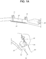
- FIG. 1A is a view showing the state in which a general curtain airbag is stored
- FIG. 1B is a view showing the state in which the general curtain airbag is deployed
- FIG. 1C is a view showing the process whereby the general curtain airbag is deployed.
- the general curtain airbag is stored in a space surrounded by an outboard 50, a headliner 52, and a trim 51 of the vehicle while an airbag cushion 10 is in a folded state.
- the airbag cushion 10 is mounted on the outboard 50 by a plurality of mounting tabs 11.
- an inflator 20 is mounted on the airbag cushion 10, and gas is supplied to an inside of the airbag cushion 10 by operation of the inflator 20, thereby inflating and deploying the same.
- a ramp configured to guide the airbag cushion 10 to be deployed toward an inside of the vehicle is separately manufactured and disposed between the airbag cushion 10 and the outboard 50.
- the ramp 30, which is a separate injection-molded plastic product, is additionally disposed therebetween, which causes a problem of increased manufacturing costs and labor for assembly.
- the present invention has been made in view of the above problems, and it is an object of the present invention to provide a curtain airbag capable of improving deployability of an airbag cushion without including a ramp component, which is a separate injection-molded plastic product.
- a curtain airbag including a main cushion provided at an upper side of a pillar of a vehicle along a forward-and-rearward direction of the vehicle and configured to be deployed by inflation thereof, and a guide cushion connected to a front area of an upper end portion of the main cushion and configured to extend toward a rear of the vehicle, the guide cushion pushing the main cushion toward an inside of the vehicle while being inflated together with the main cushion.
- the guide cushion may be divided into a primary deployment area connected to the main cushion and configured to be deployed toward an outboard of the vehicle to push the main cushion toward the inside of the vehicle, and a secondary deployment area configured to extend from the primary deployment area and to be deployed between an end portion of a trim and the main chamber to push the main chamber so as to avoid contact with the end portion of the trim.
- the primary deployment area of the guide cushion may be deployed earlier than the secondary deployment area thereof.
- a mounting hole including an inflator mounted therein may be formed in the primary deployment area of the guide cushion, and the main cushion and the guide cushion may communicate with each other at a portion adjacent to the mounting hole, and gas ejected from the inflator may flow to the main cushion and the primary deployment area of the guide cushion while being distributed thereto.
- the communication area where the main cushion and the guide cushion communicate with each other may be an area corresponding to an area where a B-pillar of the vehicle is located, or may be formed ahead of the area toward a front side of the vehicle.
- the main cushion may be folded in a roll shape, and the guide cushion may be folded around the main cushion in a shape surrounding an outside of the main cushion.
- the guide cushion may have an end portion thereof folded inwards toward the main cushion.
- the guide cushion may have an end portion thereof folded toward the inside of the vehicle.
- FIG. 2 is a view showing a deployed state of a curtain airbag according to an embodiment of the present invention
- FIG. 3A is a view showing the state in which the curtain airbag according to the embodiment of the present invention is folded
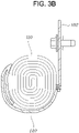
- FIGs. 3B and 3C are views showing the state in which a curtain airbag according to another embodiment of the present invention is folded.
- a curtain airbag 100 is a device disposed at an upper side of a front door and a rear door of a vehicle in a forward-and-rearward direction of the vehicle so as to protect a side surface of a passenger sitting on a vehicle seat in the event of a vehicle accident.
- the curtain airbag 100 is elongated in the forward-and-rearward direction and is mounted in a space surrounded by an outboard 50, a head liner 52, and a trim 51 forming a side portion of a vehicle body.
- the curtain airbag 100 is elongated to extend from a rear end of an A-pillar (not shown) of the vehicle to a position where a C-pillar (PC) thereof is disposed via a B-pillar (PB) thereof, and is mounted therein.
- the curtain airbag 100 will be described in detail.
- the curtain airbag according to the embodiment of the present invention includes a main cushion 110, provided at an upper side of the pillar of the vehicle along the forward-and-rearward direction of the vehicle and deployed upon inflation thereof, and a guide cushion 120, connected to a front area of an upper end portion of the main cushion 110 and configured to extend toward a rear of the vehicle, the guide cushion 120 pushing the main cushion 110 toward an inside of the vehicle while being inflated together with the main cushion 110.
- the main cushion 110 is a means that is inflated so as to expand and be deployed beside the passenger. Further, the main cushion 110 is normally folded and rolled up, and is elongated to be stored in a space surrounded by the outboard 50, the head liner 52, and the trim 51 of the vehicle along a longitudinal direction of the vehicle.
- the main cushion 110 is mounted on the outboard 50 of the vehicle via a plurality of mounting tabs 102.
- the guide cushion 120 is used as a means of guiding smooth inflation and deployment of the main cushion 110 without interfering with components forming a surrounding vehicle body such as the trim 30. Further, the guide cushion 120 is formed to be integrated with the main cushion 110.
- the guide cushion 120 is connected to the front area of the upper end portion of the main cushion 110 so that gas flows therebetween, and extends toward the rear of the vehicle. Therefore, while being inflated together with the main cushion 110, the guide cushion 120 pushes the main cushion 110 toward the inside of the vehicle at an initial stage of inflation.
- the guide cushion 120 is divided into a primary deployment area 121, which is connected to the main cushion 110 and is deployed in the outboard direction of the vehicle to push the main cushion 110 toward the inside of the vehicle, and a secondary deployment area 122, which is configured to extend from the primary deployment area 121 and to be deployed between an end portion of the trim 51 and the main cushion 110 to push the main cushion 110 so that the same does not contact the end portion of the trim 51.
- the primary deployment area 121 and the secondary deployment area 122 of the guide cushion 120 are not divided by a specific unit, but are divided along the longitudinal direction in which the guide cushion 120 is deployed.
- the primary deployment area 121 corresponds to a portion connected to the main cushion 110, that is, a front area based on the longitudinal direction of the vehicle, and the secondary deployment area 122 corresponds to a rear area extending from the primary deployment area 121.
- the guide cushion 120 is divided into the primary deployment area 121 and the secondary deployment area 122, and when gas is supplied to the inside of the guide cushion 120 and fills the same, it is preferable that the primary deployment area 121 be deployed earlier than the secondary deployment area 122.
- a mounting hole 101 having the inflator 20 mounted therein is formed in the primary deployment area 121 of the guide cushion 120.
- the main cushion 110 and the guide cushion 120 communicate with each other at a portion adjacent to the mounting hole 101. Therefore, the gas ejected from the inflator 20 flows to the main cushion 110 and the primary deployment area 121 of the guide cushion 120 while being distributed thereto.
- a communication area where the main cushion 110 and the guide cushion 120 communicate with each other prefferably be an area corresponding to an area where the B-pillar (PB) of the vehicle is located, or to be formed ahead of the aforementioned area toward the front of the vehicle. Therefore, the primary deployment area 121 of the guide cushion 120 and the secondary deployment area 122 thereof are sequentially inflated and deployed in that order.
- the main cushion 110 and the guide cushion 120 are formed by sewing edges of two sheets of fabric in the state in which the two sheets of fabric overlap each other. Therefore, the main cushion 110 and the guide cushion 120 are formed to be integrated with each other, but a specific gas path may be set by forming various sewing lines in consideration of the order in which the main cushion 110 and the guide cushion 120 are deployed and the shape thereof.
- the gas ejected from the inflator 20 it is preferable to allow the gas ejected from the inflator 20 to simultaneously flow to the main cushion 110 and the guide cushion 120 so that the primary deployment area 121 and the secondary deployment area 122 of the guide cushion 120 are sequentially deployed in an initial stage of deployment of the main cushion 110.
- the main cushion 110 and the guide cushion 120 are usually stored in a state of being folded into a roll shape.
- the guide cushion 120 be folded around the main cushion 110 in a shape surrounding the outside of the main cushion 110, which is folded and rolled up. Therefore, the guide cushion 120 is relatively earlier than the main cushion 110 in the initial stage of deployment of the main cushion 110 and the guide cushion 120, and, as such, the main cushion 110 is pushed toward the inside of the vehicle by the inflated and deployed guide cushion 120.
- the shape in which the guide cushion 120 is folded around the main cushion 110 is not limited thereto, and the guide cushion 120 may be folded around the outside of the main cushion 110 in various ways.
- an end portion of the guide cushion 120 may be folded inwards toward the main cushion 110.
- the end portion of the guide cushion 120 may be folded toward the inside of the vehicle.
- FIGs. 4A to 4C are views showing the process whereby the curtain airbag according to the embodiment of the present invention is deployed.
- FIG. 4A is a view showing the state in which the curtain airbag is usually stored, and the main cushion 110 and the guide cushion 120 are folded together in a roll shape and stored in the space surrounded by the outboard 50, the head liner 52, and the trim 51.
- the inflator 20 is operated to eject gas. After that, the ejected gas inflates the primary deployment area 121 of the guide cushion 120 and simultaneously flows to the main cushion 110 to inflate the same.
- the primary deployment area 121 of the guide cushion 120 is first inflated and deployed.
- the primary deployment area 121 of the guide cushion 120 is inflated between the main cushion 110 and the outboard 50 of the vehicle, and is deployed in a direction such that the main cushion 110 is pushed toward the inside of the vehicle.
- the main cushion 110 starts to be inflated.
- the secondary deployment area 122 of the guide cushion 120 folded around and surrounding the outside of the main cushion 110, is unfolded, and, as such, the secondary deployment area 122 thereof is located between the main cushion 110 and the trim 51.
- the main cushion 110 is completely deployed.
- the present invention allows the main cushion 110 to be deployed without interfering with the trim 51 by sequentially deploying the primary deployment area 121 and the secondary deployment area 122 of the guide cushion 120, thereby improving the deployability thereof.
- a separate component such as the ramp 30 of the related art is not necessary, thereby making it possible not only to reduce the cost of manufacturing the curtain airbag 100 but also to eliminate labor required for ramp assembly.
- a guide cushion extending from a main cushion is provided to push the main cushion toward an inside of the vehicle at an initial stage of inflation of the main cushion, thereby improving reliability of deployment of the main cushion.
- the component since it is not necessary to include a component such as a ramp of the related art, which is a separate injection-molded plastic product, the component guiding a deployment direction of the main cushion, it is possible not only to reduce the cost of manufacturing the curtain airbag but also to eliminate labor required for ramp assembly, thereby improving productivity of the curtain airbag.
Landscapes
- Engineering & Computer Science (AREA)
- Mechanical Engineering (AREA)
- Physics & Mathematics (AREA)
- Fluid Mechanics (AREA)
- Air Bags (AREA)
Abstract
Description
- This application claims priority from
Korean Patent Application No. 10-2021-0072218, filed on June 3, 2021 - The present invention relates to a curtain airbag, and more particularly to a curtain airbag that improves the deployability of an airbag cushion without including a ramp component.
- In general, a curtain airbag device is a device that protects a passenger from a side impact in the event of an accident.
- A curtain airbag is disposed at an upper portion of a front door and a rear door of a vehicle and is oriented in a forward-and-rearward direction of a vehicle body. For example, the curtain airbag is normally stored in a folded state inside a side inner panel disposed in an upper portion of an A-pillar and a C-pillar of the vehicle. In addition, when a collision signal is detected by a sensor when a collision of the vehicle occurs, gas is supplied to an airbag cushion forming the curtain airbag through an inflator. Accordingly, when the airbag cushion is deployed downwards, a side portion of the passenger is protected from the impact of the vehicle.
-
FIG. 1A is a view showing the state in which a general curtain airbag is stored,FIG. 1B is a view showing the state in which the general curtain airbag is deployed, andFIG. 1C is a view showing the process whereby the general curtain airbag is deployed. - As shown in
FIGs. 1A to 1C , the general curtain airbag is stored in a space surrounded by anoutboard 50, aheadliner 52, and atrim 51 of the vehicle while anairbag cushion 10 is in a folded state. In this case, theairbag cushion 10 is mounted on theoutboard 50 by a plurality ofmounting tabs 11. Further, aninflator 20 is mounted on theairbag cushion 10, and gas is supplied to an inside of theairbag cushion 10 by operation of theinflator 20, thereby inflating and deploying the same. - Particularly, in the related art, in order to prevent the
airbag cushion 10 from interfering with an end portion of thetrim 51 during the deployment thereof, a ramp (ramp 30) configured to guide theairbag cushion 10 to be deployed toward an inside of the vehicle is separately manufactured and disposed between theairbag cushion 10 and theoutboard 50. - As described above, in the case of the curtain airbag of the related art, in order to allow the
airbag cushion 10 to be deployed without interfering with the end portion of thetrim 51, theramp 30, which is a separate injection-molded plastic product, is additionally disposed therebetween, which causes a problem of increased manufacturing costs and labor for assembly. - The information disclosed in this Background of the Invention section is only for enhancement of understanding of the general background of the invention, and should not be taken as an acknowledgement or any form of suggestion that this information forms the related art already known to a person skilled in the art.
- Therefore, the present invention has been made in view of the above problems, and it is an object of the present invention to provide a curtain airbag capable of improving deployability of an airbag cushion without including a ramp component, which is a separate injection-molded plastic product.
- In accordance with the present invention, the above and other objects can be accomplished by the provision of a curtain airbag including a main cushion provided at an upper side of a pillar of a vehicle along a forward-and-rearward direction of the vehicle and configured to be deployed by inflation thereof, and a guide cushion connected to a front area of an upper end portion of the main cushion and configured to extend toward a rear of the vehicle, the guide cushion pushing the main cushion toward an inside of the vehicle while being inflated together with the main cushion.
- The guide cushion may be divided into a primary deployment area connected to the main cushion and configured to be deployed toward an outboard of the vehicle to push the main cushion toward the inside of the vehicle, and a secondary deployment area configured to extend from the primary deployment area and to be deployed between an end portion of a trim and the main chamber to push the main chamber so as to avoid contact with the end portion of the trim.
- The primary deployment area of the guide cushion may be deployed earlier than the secondary deployment area thereof.
- A mounting hole including an inflator mounted therein may be formed in the primary deployment area of the guide cushion, and the main cushion and the guide cushion may communicate with each other at a portion adjacent to the mounting hole, and gas ejected from the inflator may flow to the main cushion and the primary deployment area of the guide cushion while being distributed thereto.
- The communication area where the main cushion and the guide cushion communicate with each other may be an area corresponding to an area where a B-pillar of the vehicle is located, or may be formed ahead of the area toward a front side of the vehicle.
- The main cushion may be folded in a roll shape, and the guide cushion may be folded around the main cushion in a shape surrounding an outside of the main cushion.
- The guide cushion may have an end portion thereof folded inwards toward the main cushion.
- The guide cushion may have an end portion thereof folded toward the inside of the vehicle.
- The above and other objects, features and other advantages of the present invention will be more clearly understood from the following detailed description taken in conjunction with the accompanying drawings, in which:
-
FIG. 1A is a view showing the state in which a general curtain airbag is stored; -
FIG. 1B is a view showing the state in which the general curtain airbag is deployed; -
FIG. 1C is a view showing the process whereby the general curtain airbag is deployed; -
FIG. 2 is a view showing a deployed state of a curtain airbag according to an embodiment of the present invention; -
FIG. 3A is a view showing the state in which the curtain airbag according to the embodiment of the present invention is folded; -
FIGs. 3B and3C are views showing the state in which a curtain airbag according to another embodiment of the present invention is folded; and -
FIGs. 4A to 4C are views showing the process whereby the curtain airbag according to the embodiment of the present invention is deployed. - Hereinafter, embodiments of the present invention will be described in more detail with reference to the accompanying drawings. However, the present invention is not limited to the embodiments disclosed below, but will be implemented in various different forms. The embodiments are provided to ensure that the disclosure of the present invention is complete and to fully inform a person having ordinary skill in the art of the scope of the invention. Wherever possible, the same reference numbers will be used throughout the drawings to refer to the same or like parts.
-
FIG. 2 is a view showing a deployed state of a curtain airbag according to an embodiment of the present invention,FIG. 3A is a view showing the state in which the curtain airbag according to the embodiment of the present invention is folded, andFIGs. 3B and3C are views showing the state in which a curtain airbag according to another embodiment of the present invention is folded. - As shown in the drawing, a
curtain airbag 100 according to the embodiment of the present invention is a device disposed at an upper side of a front door and a rear door of a vehicle in a forward-and-rearward direction of the vehicle so as to protect a side surface of a passenger sitting on a vehicle seat in the event of a vehicle accident. To this end, thecurtain airbag 100 is elongated in the forward-and-rearward direction and is mounted in a space surrounded by anoutboard 50, ahead liner 52, and atrim 51 forming a side portion of a vehicle body. More specifically, thecurtain airbag 100 is elongated to extend from a rear end of an A-pillar (not shown) of the vehicle to a position where a C-pillar (PC) thereof is disposed via a B-pillar (PB) thereof, and is mounted therein. - The
curtain airbag 100 will be described in detail. The curtain airbag according to the embodiment of the present invention includes amain cushion 110, provided at an upper side of the pillar of the vehicle along the forward-and-rearward direction of the vehicle and deployed upon inflation thereof, and aguide cushion 120, connected to a front area of an upper end portion of themain cushion 110 and configured to extend toward a rear of the vehicle, theguide cushion 120 pushing themain cushion 110 toward an inside of the vehicle while being inflated together with themain cushion 110. - The
main cushion 110 is a means that is inflated so as to expand and be deployed beside the passenger. Further, themain cushion 110 is normally folded and rolled up, and is elongated to be stored in a space surrounded by theoutboard 50, thehead liner 52, and thetrim 51 of the vehicle along a longitudinal direction of the vehicle. - In this case, the
main cushion 110 is mounted on theoutboard 50 of the vehicle via a plurality ofmounting tabs 102. - Meanwhile, when the
main cushion 110 is deployed, theguide cushion 120 is used as a means of guiding smooth inflation and deployment of themain cushion 110 without interfering with components forming a surrounding vehicle body such as thetrim 30. Further, theguide cushion 120 is formed to be integrated with themain cushion 110. - For example, the
guide cushion 120 is connected to the front area of the upper end portion of themain cushion 110 so that gas flows therebetween, and extends toward the rear of the vehicle. Therefore, while being inflated together with themain cushion 110, theguide cushion 120 pushes themain cushion 110 toward the inside of the vehicle at an initial stage of inflation. - Specifically, the
guide cushion 120 is divided into aprimary deployment area 121, which is connected to themain cushion 110 and is deployed in the outboard direction of the vehicle to push themain cushion 110 toward the inside of the vehicle, and asecondary deployment area 122, which is configured to extend from theprimary deployment area 121 and to be deployed between an end portion of the trim 51 and themain cushion 110 to push themain cushion 110 so that the same does not contact the end portion of the trim 51. - In this case, the
primary deployment area 121 and thesecondary deployment area 122 of theguide cushion 120 are not divided by a specific unit, but are divided along the longitudinal direction in which theguide cushion 120 is deployed. Theprimary deployment area 121 corresponds to a portion connected to themain cushion 110, that is, a front area based on the longitudinal direction of the vehicle, and thesecondary deployment area 122 corresponds to a rear area extending from theprimary deployment area 121. - As described above, the
guide cushion 120 is divided into theprimary deployment area 121 and thesecondary deployment area 122, and when gas is supplied to the inside of theguide cushion 120 and fills the same, it is preferable that theprimary deployment area 121 be deployed earlier than thesecondary deployment area 122. - To this end, a mounting
hole 101 having the inflator 20 mounted therein is formed in theprimary deployment area 121 of theguide cushion 120. - In addition, the
main cushion 110 and theguide cushion 120 communicate with each other at a portion adjacent to the mountinghole 101. Therefore, the gas ejected from the inflator 20 flows to themain cushion 110 and theprimary deployment area 121 of theguide cushion 120 while being distributed thereto. - In this case, it is preferable for a communication area where the
main cushion 110 and theguide cushion 120 communicate with each other to be an area corresponding to an area where the B-pillar (PB) of the vehicle is located, or to be formed ahead of the aforementioned area toward the front of the vehicle. Therefore, theprimary deployment area 121 of theguide cushion 120 and thesecondary deployment area 122 thereof are sequentially inflated and deployed in that order. - Meanwhile, the
main cushion 110 and theguide cushion 120 are formed by sewing edges of two sheets of fabric in the state in which the two sheets of fabric overlap each other. Therefore, themain cushion 110 and theguide cushion 120 are formed to be integrated with each other, but a specific gas path may be set by forming various sewing lines in consideration of the order in which themain cushion 110 and theguide cushion 120 are deployed and the shape thereof. - In this embodiment, as described above, it is preferable to allow the gas ejected from the inflator 20 to simultaneously flow to the
main cushion 110 and theguide cushion 120 so that theprimary deployment area 121 and thesecondary deployment area 122 of theguide cushion 120 are sequentially deployed in an initial stage of deployment of themain cushion 110. - Meanwhile, the
main cushion 110 and theguide cushion 120 are usually stored in a state of being folded into a roll shape. - Here, as shown in
FIG. 3A , it is preferable that theguide cushion 120 be folded around themain cushion 110 in a shape surrounding the outside of themain cushion 110, which is folded and rolled up. Therefore, theguide cushion 120 is relatively earlier than themain cushion 110 in the initial stage of deployment of themain cushion 110 and theguide cushion 120, and, as such, themain cushion 110 is pushed toward the inside of the vehicle by the inflated and deployedguide cushion 120. - However, the shape in which the
guide cushion 120 is folded around themain cushion 110 is not limited thereto, and theguide cushion 120 may be folded around the outside of themain cushion 110 in various ways. - For example, as shown in
FIG. 3B , an end portion of theguide cushion 120 may be folded inwards toward themain cushion 110. - In addition, as shown in
FIG. 3C , the end portion of theguide cushion 120 may be folded toward the inside of the vehicle. - Next, an embodiment of the process whereby the curtain airbag according to the embodiment of the present invention configured as described above is deployed will be described.
-
FIGs. 4A to 4C are views showing the process whereby the curtain airbag according to the embodiment of the present invention is deployed. -
FIG. 4A is a view showing the state in which the curtain airbag is usually stored, and themain cushion 110 and theguide cushion 120 are folded together in a roll shape and stored in the space surrounded by the outboard 50, thehead liner 52, and the trim 51. - In this state, when an accident occurs, the
inflator 20 is operated to eject gas. After that, the ejected gas inflates theprimary deployment area 121 of theguide cushion 120 and simultaneously flows to themain cushion 110 to inflate the same. - Next, as shown in
FIG. 4B , theprimary deployment area 121 of theguide cushion 120 is first inflated and deployed. In this case, theprimary deployment area 121 of theguide cushion 120 is inflated between themain cushion 110 and the outboard 50 of the vehicle, and is deployed in a direction such that themain cushion 110 is pushed toward the inside of the vehicle. - Meanwhile, while the
primary deployment area 121 of theguide cushion 120 is inflated, themain cushion 110 starts to be inflated. At this time, thesecondary deployment area 122 of theguide cushion 120, folded around and surrounding the outside of themain cushion 110, is unfolded, and, as such, thesecondary deployment area 122 thereof is located between themain cushion 110 and the trim 51. - In this state, when gas is continuously ejected from the inflator 20, as shown in
FIG. 4C , the gas is inflated and deployed up to thesecondary deployment area 122 of theguide cushion 120, and the deployedsecondary deployment area 122 of theguide cushion 120 pushes away themain cushion 110, which is currently being deployed, from the trim 51. - Next, as the gas is continuously supplied to the
main cushion 110, themain cushion 110 is completely deployed. - In this manner, the present invention allows the
main cushion 110 to be deployed without interfering with the trim 51 by sequentially deploying theprimary deployment area 121 and thesecondary deployment area 122 of theguide cushion 120, thereby improving the deployability thereof. Particularly, in order to deploy themain cushion 110 while avoiding the trim 51, a separate component such as theramp 30 of the related art is not necessary, thereby making it possible not only to reduce the cost of manufacturing thecurtain airbag 100 but also to eliminate labor required for ramp assembly. - As is apparent from the above description, a guide cushion extending from a main cushion is provided to push the main cushion toward an inside of the vehicle at an initial stage of inflation of the main cushion, thereby improving reliability of deployment of the main cushion.
- Particularly, since it is not necessary to include a component such as a ramp of the related art, which is a separate injection-molded plastic product, the component guiding a deployment direction of the main cushion, it is possible not only to reduce the cost of manufacturing the curtain airbag but also to eliminate labor required for ramp assembly, thereby improving productivity of the curtain airbag.
- Although the present invention has been described with reference to the accompanying drawings and preferred embodiments, the present invention is not limited thereto, and is defined by the appended claims and their equivalents. Therefore, it will be appreciated by those skilled in the art that various modifications and changes can be made to these embodiments without departing from the spirit and scope of the invention as defined by the appended claims.
Claims (8)
- A curtain airbag comprising:a main cushion configured to be provided at an upper side of a pillar of a vehicle along a forward-and-rearward direction of the vehicle and configured to be deployed upon inflation thereof; anda guide cushion connected to a front area of an upper end portion of the main cushion and configured to extend toward a rear of the vehicle, the guide cushion pushing the main cushion toward an inside of the vehicle while being inflated together with the main cushion.
- The curtain airbag according to claim 1, wherein the guide cushion comprises:a primary deployment area connected to the main cushion and configured to be deployed toward an outboard of the vehicle to push the main cushion toward the inside of the vehicle; anda secondary deployment area configured to extend from the primary deployment area and to be deployed between an end portion of a trim and a main chamber to push the main chamber to avoid contact with the end portion of the trim.
- The curtain airbag according to claim 2, wherein the primary deployment area of the guide cushion is configured to deploy earlier than the secondary deployment area.
- The curtain airbag according to claim 2, wherein:a mounting hole, comprising an inflator mounted therein, is formed in the primary deployment area of the guide cushion, andthe main cushion and the guide cushion communicate with each other at a portion adjacent to the mounting hole, and gas ejected from the inflator flows to the main cushion and the primary deployment area of the guide cushion while being distributed thereto.
- The curtain airbag according to claim 4, wherein a communication area where the main cushion and the guide cushion communicate with each other is an area corresponding to an area where a B-pillar of the vehicle is located, or is formed ahead of the area toward a front side of the vehicle.
- The curtain airbag according to claim 1, wherein:the main cushion is folded in a roll shape, andthe guide cushion is folded around the main cushion in a shape surrounding an outside of the main cushion.
- The curtain airbag according to claim 6, wherein the guide cushion has an end portion thereof folded inwards toward the main cushion.
- The curtain airbag according to claim 6, wherein the guide cushion has an end portion thereof folded toward the inside of the vehicle.
Applications Claiming Priority (1)
| Application Number | Priority Date | Filing Date | Title |
|---|---|---|---|
| KR1020210072218A KR20220163720A (en) | 2021-06-03 | 2021-06-03 | Curtain airbag |
Publications (2)
| Publication Number | Publication Date |
|---|---|
| EP4098495A2 true EP4098495A2 (en) | 2022-12-07 |
| EP4098495A3 EP4098495A3 (en) | 2022-12-14 |
Family
ID=81850238
Family Applications (1)
| Application Number | Title | Priority Date | Filing Date |
|---|---|---|---|
| EP22175259.5A Pending EP4098495A3 (en) | 2021-06-03 | 2022-05-24 | Curtain airbag |
Country Status (4)
| Country | Link |
|---|---|
| US (1) | US11858449B2 (en) |
| EP (1) | EP4098495A3 (en) |
| KR (1) | KR20220163720A (en) |
| CN (1) | CN217672543U (en) |
Families Citing this family (1)
| Publication number | Priority date | Publication date | Assignee | Title |
|---|---|---|---|---|
| KR20230127546A (en) * | 2022-02-25 | 2023-09-01 | 현대모비스 주식회사 | Curtain air bag |
Family Cites Families (25)
| Publication number | Priority date | Publication date | Assignee | Title |
|---|---|---|---|---|
| US6830262B2 (en) * | 2002-07-11 | 2004-12-14 | Autoliv Asp, Inc. | Inflatable airbag deployment guide |
| US7185914B2 (en) * | 2003-09-24 | 2007-03-06 | Autoliv Asp, Inc. | Inflatable curtain with pleats |
| DE102005002085B4 (en) * | 2004-03-17 | 2013-09-05 | TAKATA Aktiengesellschaft | Side air bag device |
| DE102005011676B4 (en) * | 2005-03-11 | 2012-04-19 | Autoliv Development Ab | Curtain airbag and motor vehicle |
| KR100656618B1 (en) * | 2005-11-21 | 2006-12-11 | 현대자동차주식회사 | Curtain air bag for vehicle |
| WO2008011414A2 (en) * | 2006-07-17 | 2008-01-24 | Delphi Technologies, Inc. | Side curtain airbag with extended shoulder portion |
| DE102006061968A1 (en) * | 2006-12-21 | 2008-07-03 | Autoliv Development Ab | Curtain airbag |
| JP5518707B2 (en) * | 2008-06-27 | 2014-06-11 | オートリブ ディベロップメント エービー | Curtain airbag device for vehicle |
| US8408591B2 (en) * | 2009-04-17 | 2013-04-02 | Autoliv Asp, Inc. | Inflatable curtain airbags with expanded-volume lower portions for ejection mitigation |
| US8020888B2 (en) * | 2009-10-05 | 2011-09-20 | Autoliv Asp, Inc. | Vehicle curtain airbag |
| DE102009049764B4 (en) * | 2009-10-16 | 2016-02-18 | Autoliv Development Ab | An air bag assembly |
| JP5471953B2 (en) * | 2010-08-05 | 2014-04-16 | 豊田合成株式会社 | Head protection airbag device |
| WO2012154851A2 (en) * | 2011-05-10 | 2012-11-15 | Tk Holdings Inc. | Side-impact airbag module |
| JP6003720B2 (en) * | 2013-02-28 | 2016-10-05 | 豊田合成株式会社 | Head protection airbag device |
| JP6181443B2 (en) * | 2013-07-04 | 2017-08-16 | オートリブ ディベロップメント エービー | Curtain airbag device for vehicle |
| KR102605170B1 (en) * | 2016-06-22 | 2023-11-27 | 현대모비스 주식회사 | Curtain airbag apparatus |
| KR102083142B1 (en) * | 2016-09-05 | 2020-03-02 | 현대모비스 주식회사 | Curtain airbag apparatus |
| KR101867061B1 (en) * | 2016-10-05 | 2018-06-14 | 아우토리브 디벨롭먼트 아베 | Curtain airbag for vehicle |
| US9963102B1 (en) * | 2016-10-18 | 2018-05-08 | Autoliv Asp, Inc. | Top fill curtain airbags |
| KR102647194B1 (en) * | 2018-11-16 | 2024-03-13 | 현대자동차주식회사 | Curtain airbag for vehicle |
| KR102641419B1 (en) * | 2019-04-12 | 2024-02-27 | 현대모비스 주식회사 | Curtain air bag device |
| KR20200120218A (en) * | 2019-04-12 | 2020-10-21 | 현대모비스 주식회사 | Curtain airbag apparatus |
| KR20210010049A (en) | 2019-07-19 | 2021-01-27 | 현대모비스 주식회사 | Curtain airbag apparatus |
| US11685332B2 (en) * | 2019-09-03 | 2023-06-27 | ZF Passive Safety Systems US Inc. | Vehicle airbag |
| KR102580397B1 (en) * | 2021-04-27 | 2023-09-20 | 현대모비스 주식회사 | Curtain air bag |
-
2021
- 2021-06-03 KR KR1020210072218A patent/KR20220163720A/en unknown
-
2022
- 2022-05-06 US US17/662,398 patent/US11858449B2/en active Active
- 2022-05-24 EP EP22175259.5A patent/EP4098495A3/en active Pending
- 2022-06-01 CN CN202221381116.0U patent/CN217672543U/en active Active
Also Published As
| Publication number | Publication date |
|---|---|
| EP4098495A3 (en) | 2022-12-14 |
| US11858449B2 (en) | 2024-01-02 |
| US20220388469A1 (en) | 2022-12-08 |
| KR20220163720A (en) | 2022-12-12 |
| CN217672543U (en) | 2022-10-28 |
Similar Documents
| Publication | Publication Date | Title |
|---|---|---|
| US8876153B2 (en) | Airbag assembly | |
| US8764053B1 (en) | Airbag assembly | |
| JP6265190B2 (en) | Car occupant protection device | |
| JP5149383B2 (en) | Airbag device | |
| US7658403B2 (en) | Side airbag apparatus | |
| JP4879215B2 (en) | Knee airbag and its folding method | |
| US7992892B2 (en) | Inflatable ramp for inflatable curtain side impact restraint | |
| EP2572944B1 (en) | Curtain air bag device and vehicle | |
| JP2008056116A (en) | Head protection airbag device | |
| KR20160025370A (en) | Curtain Airbag Of Vehicle | |
| US10556565B2 (en) | Curtain airbag apparatus | |
| US8740247B1 (en) | Airbag assembly | |
| EP1953046B1 (en) | Vehicle occupant restraint system | |
| US10322693B2 (en) | Vehicle airbag | |
| US7234728B2 (en) | Airbag system | |
| WO2009144971A1 (en) | Head-restraining airbag system | |
| EP4098495A2 (en) | Curtain airbag | |
| US20080111354A1 (en) | Apparatus for guiding deployment of curtain airbag for vehicle | |
| KR102096841B1 (en) | Curtain airbag of vehicle | |
| JP6233198B2 (en) | Airbag device for vehicle | |
| CN108016398B (en) | Side curtain airbag assembly | |
| KR102543716B1 (en) | Side airbag apparatus for vehicle | |
| KR100640008B1 (en) | Side air-bag for vehicles | |
| KR102366814B1 (en) | Curtain air bag and deployment method of curtain air bag | |
| KR20180037809A (en) | Curtain airbag for vehicle |
Legal Events
| Date | Code | Title | Description |
|---|---|---|---|
| PUAI | Public reference made under article 153(3) epc to a published international application that has entered the european phase |
Free format text: ORIGINAL CODE: 0009012 |
|
| STAA | Information on the status of an ep patent application or granted ep patent |
Free format text: STATUS: REQUEST FOR EXAMINATION WAS MADE |
|
| PUAL | Search report despatched |
Free format text: ORIGINAL CODE: 0009013 |
|
| 17P | Request for examination filed |
Effective date: 20220624 |
|
| AK | Designated contracting states |
Kind code of ref document: A2 Designated state(s): AL AT BE BG CH CY CZ DE DK EE ES FI FR GB GR HR HU IE IS IT LI LT LU LV MC MK MT NL NO PL PT RO RS SE SI SK SM TR |
|
| AK | Designated contracting states |
Kind code of ref document: A3 Designated state(s): AL AT BE BG CH CY CZ DE DK EE ES FI FR GB GR HR HU IE IS IT LI LT LU LV MC MK MT NL NO PL PT RO RS SE SI SK SM TR |
|
| RIC1 | Information provided on ipc code assigned before grant |
Ipc: B60R 21/233 20060101ALI20221104BHEP Ipc: B60R 21/232 20110101ALI20221104BHEP Ipc: B60R 21/213 20110101AFI20221104BHEP |
|
| RBV | Designated contracting states (corrected) |
Designated state(s): AL AT BE BG CH CY CZ DE DK EE ES FI FR GB GR HR HU IE IS IT LI LT LU LV MC MK MT NL NO PL PT RO RS SE SI SK SM TR |