EP4098469A1 - Head-up display device, and vehicle - Google Patents
Head-up display device, and vehicle Download PDFInfo
- Publication number
- EP4098469A1 EP4098469A1 EP22173694.5A EP22173694A EP4098469A1 EP 4098469 A1 EP4098469 A1 EP 4098469A1 EP 22173694 A EP22173694 A EP 22173694A EP 4098469 A1 EP4098469 A1 EP 4098469A1
- Authority
- EP
- European Patent Office
- Prior art keywords
- information
- line segment
- image signal
- vehicle
- image forming
- Prior art date
- Legal status (The legal status is an assumption and is not a legal conclusion. Google has not performed a legal analysis and makes no representation as to the accuracy of the status listed.)
- Granted
Links
Images


Classifications
-
- G—PHYSICS
- G06—COMPUTING OR CALCULATING; COUNTING
- G06T—IMAGE DATA PROCESSING OR GENERATION, IN GENERAL
- G06T11/00—Two-dimensional [2D] image generation
- G06T11/20—Drawing from basic elements
- G06T11/23—Drawing from basic elements using straight lines or curves
-
- B—PERFORMING OPERATIONS; TRANSPORTING
- B60—VEHICLES IN GENERAL
- B60K—ARRANGEMENT OR MOUNTING OF PROPULSION UNITS OR OF TRANSMISSIONS IN VEHICLES; ARRANGEMENT OR MOUNTING OF PLURAL DIVERSE PRIME-MOVERS IN VEHICLES; AUXILIARY DRIVES FOR VEHICLES; INSTRUMENTATION OR DASHBOARDS FOR VEHICLES; ARRANGEMENTS IN CONNECTION WITH COOLING, AIR INTAKE, GAS EXHAUST OR FUEL SUPPLY OF PROPULSION UNITS IN VEHICLES
- B60K35/00—Instruments specially adapted for vehicles; Arrangement of instruments in or on vehicles
- B60K35/20—Output arrangements, i.e. from vehicle to user, associated with vehicle functions or specially adapted therefor
- B60K35/21—Output arrangements, i.e. from vehicle to user, associated with vehicle functions or specially adapted therefor using visual output, e.g. blinking lights or matrix displays
- B60K35/23—Head-up displays [HUD]
-
- B—PERFORMING OPERATIONS; TRANSPORTING
- B60—VEHICLES IN GENERAL
- B60K—ARRANGEMENT OR MOUNTING OF PROPULSION UNITS OR OF TRANSMISSIONS IN VEHICLES; ARRANGEMENT OR MOUNTING OF PLURAL DIVERSE PRIME-MOVERS IN VEHICLES; AUXILIARY DRIVES FOR VEHICLES; INSTRUMENTATION OR DASHBOARDS FOR VEHICLES; ARRANGEMENTS IN CONNECTION WITH COOLING, AIR INTAKE, GAS EXHAUST OR FUEL SUPPLY OF PROPULSION UNITS IN VEHICLES
- B60K35/00—Instruments specially adapted for vehicles; Arrangement of instruments in or on vehicles
- B60K35/20—Output arrangements, i.e. from vehicle to user, associated with vehicle functions or specially adapted therefor
- B60K35/28—Output arrangements, i.e. from vehicle to user, associated with vehicle functions or specially adapted therefor characterised by the type of the output information, e.g. video entertainment or vehicle dynamics information; characterised by the purpose of the output information, e.g. for attracting the attention of the driver
-
- B—PERFORMING OPERATIONS; TRANSPORTING
- B60—VEHICLES IN GENERAL
- B60K—ARRANGEMENT OR MOUNTING OF PROPULSION UNITS OR OF TRANSMISSIONS IN VEHICLES; ARRANGEMENT OR MOUNTING OF PLURAL DIVERSE PRIME-MOVERS IN VEHICLES; AUXILIARY DRIVES FOR VEHICLES; INSTRUMENTATION OR DASHBOARDS FOR VEHICLES; ARRANGEMENTS IN CONNECTION WITH COOLING, AIR INTAKE, GAS EXHAUST OR FUEL SUPPLY OF PROPULSION UNITS IN VEHICLES
- B60K35/00—Instruments specially adapted for vehicles; Arrangement of instruments in or on vehicles
- B60K35/20—Output arrangements, i.e. from vehicle to user, associated with vehicle functions or specially adapted therefor
- B60K35/29—Instruments characterised by the way in which information is handled, e.g. showing information on plural displays or prioritising information according to driving conditions
-
- B—PERFORMING OPERATIONS; TRANSPORTING
- B60—VEHICLES IN GENERAL
- B60K—ARRANGEMENT OR MOUNTING OF PROPULSION UNITS OR OF TRANSMISSIONS IN VEHICLES; ARRANGEMENT OR MOUNTING OF PLURAL DIVERSE PRIME-MOVERS IN VEHICLES; AUXILIARY DRIVES FOR VEHICLES; INSTRUMENTATION OR DASHBOARDS FOR VEHICLES; ARRANGEMENTS IN CONNECTION WITH COOLING, AIR INTAKE, GAS EXHAUST OR FUEL SUPPLY OF PROPULSION UNITS IN VEHICLES
- B60K35/00—Instruments specially adapted for vehicles; Arrangement of instruments in or on vehicles
- B60K35/60—Instruments characterised by their location or relative disposition in or on vehicles
-
- B—PERFORMING OPERATIONS; TRANSPORTING
- B60—VEHICLES IN GENERAL
- B60K—ARRANGEMENT OR MOUNTING OF PROPULSION UNITS OR OF TRANSMISSIONS IN VEHICLES; ARRANGEMENT OR MOUNTING OF PLURAL DIVERSE PRIME-MOVERS IN VEHICLES; AUXILIARY DRIVES FOR VEHICLES; INSTRUMENTATION OR DASHBOARDS FOR VEHICLES; ARRANGEMENTS IN CONNECTION WITH COOLING, AIR INTAKE, GAS EXHAUST OR FUEL SUPPLY OF PROPULSION UNITS IN VEHICLES
- B60K35/00—Instruments specially adapted for vehicles; Arrangement of instruments in or on vehicles
- B60K35/80—Arrangements for controlling instruments
- B60K35/81—Arrangements for controlling instruments for controlling displays
-
- G—PHYSICS
- G02—OPTICS
- G02B—OPTICAL ELEMENTS, SYSTEMS OR APPARATUS
- G02B27/00—Optical systems or apparatus not provided for by any of the groups G02B1/00 - G02B26/00, G02B30/00
- G02B27/01—Head-up displays
-
- G—PHYSICS
- G02—OPTICS
- G02B—OPTICAL ELEMENTS, SYSTEMS OR APPARATUS
- G02B27/00—Optical systems or apparatus not provided for by any of the groups G02B1/00 - G02B26/00, G02B30/00
- G02B27/01—Head-up displays
- G02B27/0101—Head-up displays characterised by optical features
-
- G—PHYSICS
- G09—EDUCATION; CRYPTOGRAPHY; DISPLAY; ADVERTISING; SEALS
- G09G—ARRANGEMENTS OR CIRCUITS FOR CONTROL OF INDICATING DEVICES USING STATIC MEANS TO PRESENT VARIABLE INFORMATION
- G09G3/00—Control arrangements or circuits, of interest only in connection with visual indicators other than cathode-ray tubes
- G09G3/001—Control arrangements or circuits, of interest only in connection with visual indicators other than cathode-ray tubes using specific devices not provided for in groups G09G3/02 - G09G3/36, e.g. using an intermediate record carrier such as a film slide; Projection systems; Display of non-alphanumerical information, solely or in combination with alphanumerical information, e.g. digital display on projected diapositive as background
-
- B—PERFORMING OPERATIONS; TRANSPORTING
- B60—VEHICLES IN GENERAL
- B60K—ARRANGEMENT OR MOUNTING OF PROPULSION UNITS OR OF TRANSMISSIONS IN VEHICLES; ARRANGEMENT OR MOUNTING OF PLURAL DIVERSE PRIME-MOVERS IN VEHICLES; AUXILIARY DRIVES FOR VEHICLES; INSTRUMENTATION OR DASHBOARDS FOR VEHICLES; ARRANGEMENTS IN CONNECTION WITH COOLING, AIR INTAKE, GAS EXHAUST OR FUEL SUPPLY OF PROPULSION UNITS IN VEHICLES
- B60K2360/00—Indexing scheme associated with groups B60K35/00 or B60K37/00 relating to details of instruments or dashboards
- B60K2360/16—Type of output information
- B60K2360/166—Navigation
-
- B—PERFORMING OPERATIONS; TRANSPORTING
- B60—VEHICLES IN GENERAL
- B60K—ARRANGEMENT OR MOUNTING OF PROPULSION UNITS OR OF TRANSMISSIONS IN VEHICLES; ARRANGEMENT OR MOUNTING OF PLURAL DIVERSE PRIME-MOVERS IN VEHICLES; AUXILIARY DRIVES FOR VEHICLES; INSTRUMENTATION OR DASHBOARDS FOR VEHICLES; ARRANGEMENTS IN CONNECTION WITH COOLING, AIR INTAKE, GAS EXHAUST OR FUEL SUPPLY OF PROPULSION UNITS IN VEHICLES
- B60K2360/00—Indexing scheme associated with groups B60K35/00 or B60K37/00 relating to details of instruments or dashboards
- B60K2360/16—Type of output information
- B60K2360/167—Vehicle dynamics information
-
- B—PERFORMING OPERATIONS; TRANSPORTING
- B60—VEHICLES IN GENERAL
- B60K—ARRANGEMENT OR MOUNTING OF PROPULSION UNITS OR OF TRANSMISSIONS IN VEHICLES; ARRANGEMENT OR MOUNTING OF PLURAL DIVERSE PRIME-MOVERS IN VEHICLES; AUXILIARY DRIVES FOR VEHICLES; INSTRUMENTATION OR DASHBOARDS FOR VEHICLES; ARRANGEMENTS IN CONNECTION WITH COOLING, AIR INTAKE, GAS EXHAUST OR FUEL SUPPLY OF PROPULSION UNITS IN VEHICLES
- B60K2360/00—Indexing scheme associated with groups B60K35/00 or B60K37/00 relating to details of instruments or dashboards
- B60K2360/16—Type of output information
- B60K2360/177—Augmented reality
-
- B—PERFORMING OPERATIONS; TRANSPORTING
- B60—VEHICLES IN GENERAL
- B60K—ARRANGEMENT OR MOUNTING OF PROPULSION UNITS OR OF TRANSMISSIONS IN VEHICLES; ARRANGEMENT OR MOUNTING OF PLURAL DIVERSE PRIME-MOVERS IN VEHICLES; AUXILIARY DRIVES FOR VEHICLES; INSTRUMENTATION OR DASHBOARDS FOR VEHICLES; ARRANGEMENTS IN CONNECTION WITH COOLING, AIR INTAKE, GAS EXHAUST OR FUEL SUPPLY OF PROPULSION UNITS IN VEHICLES
- B60K2360/00—Indexing scheme associated with groups B60K35/00 or B60K37/00 relating to details of instruments or dashboards
- B60K2360/16—Type of output information
- B60K2360/179—Distances to obstacles or vehicles
-
- B—PERFORMING OPERATIONS; TRANSPORTING
- B60—VEHICLES IN GENERAL
- B60K—ARRANGEMENT OR MOUNTING OF PROPULSION UNITS OR OF TRANSMISSIONS IN VEHICLES; ARRANGEMENT OR MOUNTING OF PLURAL DIVERSE PRIME-MOVERS IN VEHICLES; AUXILIARY DRIVES FOR VEHICLES; INSTRUMENTATION OR DASHBOARDS FOR VEHICLES; ARRANGEMENTS IN CONNECTION WITH COOLING, AIR INTAKE, GAS EXHAUST OR FUEL SUPPLY OF PROPULSION UNITS IN VEHICLES
- B60K2360/00—Indexing scheme associated with groups B60K35/00 or B60K37/00 relating to details of instruments or dashboards
- B60K2360/18—Information management
- B60K2360/186—Displaying information according to relevancy
- B60K2360/1868—Displaying information according to relevancy according to driving situations
-
- B—PERFORMING OPERATIONS; TRANSPORTING
- B60—VEHICLES IN GENERAL
- B60K—ARRANGEMENT OR MOUNTING OF PROPULSION UNITS OR OF TRANSMISSIONS IN VEHICLES; ARRANGEMENT OR MOUNTING OF PLURAL DIVERSE PRIME-MOVERS IN VEHICLES; AUXILIARY DRIVES FOR VEHICLES; INSTRUMENTATION OR DASHBOARDS FOR VEHICLES; ARRANGEMENTS IN CONNECTION WITH COOLING, AIR INTAKE, GAS EXHAUST OR FUEL SUPPLY OF PROPULSION UNITS IN VEHICLES
- B60K2360/00—Indexing scheme associated with groups B60K35/00 or B60K37/00 relating to details of instruments or dashboards
- B60K2360/20—Optical features of instruments
- B60K2360/31—Virtual images
-
- B—PERFORMING OPERATIONS; TRANSPORTING
- B60—VEHICLES IN GENERAL
- B60K—ARRANGEMENT OR MOUNTING OF PROPULSION UNITS OR OF TRANSMISSIONS IN VEHICLES; ARRANGEMENT OR MOUNTING OF PLURAL DIVERSE PRIME-MOVERS IN VEHICLES; AUXILIARY DRIVES FOR VEHICLES; INSTRUMENTATION OR DASHBOARDS FOR VEHICLES; ARRANGEMENTS IN CONNECTION WITH COOLING, AIR INTAKE, GAS EXHAUST OR FUEL SUPPLY OF PROPULSION UNITS IN VEHICLES
- B60K2360/00—Indexing scheme associated with groups B60K35/00 or B60K37/00 relating to details of instruments or dashboards
- B60K2360/20—Optical features of instruments
- B60K2360/33—Illumination features
- B60K2360/334—Projection means
-
- B—PERFORMING OPERATIONS; TRANSPORTING
- B60—VEHICLES IN GENERAL
- B60K—ARRANGEMENT OR MOUNTING OF PROPULSION UNITS OR OF TRANSMISSIONS IN VEHICLES; ARRANGEMENT OR MOUNTING OF PLURAL DIVERSE PRIME-MOVERS IN VEHICLES; AUXILIARY DRIVES FOR VEHICLES; INSTRUMENTATION OR DASHBOARDS FOR VEHICLES; ARRANGEMENTS IN CONNECTION WITH COOLING, AIR INTAKE, GAS EXHAUST OR FUEL SUPPLY OF PROPULSION UNITS IN VEHICLES
- B60K2360/00—Indexing scheme associated with groups B60K35/00 or B60K37/00 relating to details of instruments or dashboards
- B60K2360/77—Instrument locations other than the dashboard
- B60K2360/785—Instrument locations other than the dashboard on or in relation to the windshield or windows
-
- G—PHYSICS
- G02—OPTICS
- G02B—OPTICAL ELEMENTS, SYSTEMS OR APPARATUS
- G02B27/00—Optical systems or apparatus not provided for by any of the groups G02B1/00 - G02B26/00, G02B30/00
- G02B27/01—Head-up displays
- G02B27/0101—Head-up displays characterised by optical features
- G02B2027/0141—Head-up displays characterised by optical features characterised by the informative content of the display
-
- G—PHYSICS
- G09—EDUCATION; CRYPTOGRAPHY; DISPLAY; ADVERTISING; SEALS
- G09G—ARRANGEMENTS OR CIRCUITS FOR CONTROL OF INDICATING DEVICES USING STATIC MEANS TO PRESENT VARIABLE INFORMATION
- G09G2380/00—Specific applications
- G09G2380/10—Automotive applications
Definitions
- the present invention relates to a head-up display device and a vehicle.
- a head-up display device is a device that projects objects related to various types of driving-related information onto an image forming plane ahead of a driver seat.
- a vehicle with a head-up display device allows a driver to recognize various types of driving-related information without requiring him/her to look away from his/her viewpoint.
- Patent Literature 1 discloses a head-up display device that projects objects related to information on external factors outside a vehicle, such as a road sign and route guidance, onto the upper portion of an image forming plane, and projects objects related to information on the own vehicle, such as the vehicle speed and ON/OFF of cruise control, onto the lower portion of the image forming plane.
- Patent Literature 1 Japanese Patent No. 6354633
- the image forming plane onto which the head-up display device projects objects related to various types of information should have a shape with a short length in the up-down direction so as not to obstruct the line of vision of the driver looking ahead of the vehicle. Therefore, with the head-up display device, it would be difficult to arrange a plurality of objects, such as sign guidance and route guidance, in the up-down direction of the image forming plane sequentially along the travel route of the vehicle, unlike with a navigation device. Accordingly, with the conventional head-up display device, it has been difficult to allow a driver to intuitively recognize the nearest information and the following information sequentially along the travel route of the vehicle.
- the present invention has been made to solve the foregoing problem, and it is an object of the present invention to allow a driver to intuitively recognize a plurality of objects sequentially along a travel route of a vehicle, particularly while projecting a video onto an image forming plane that has a length in the vertical direction shorter than a length in the horizontal direction.
- a head-up display device is a device for projecting driving-related information onto an image forming plane provided ahead of a driver seat, including a controller and an optical processor.
- the controller receives the driving-related information, and generates an image signal from the received driving-related information.
- the optical processor obtains the image signal from the controller, and outputs a light beam to the image forming plane.
- the controller includes a first information receiving unit, a second information receiving unit, and an image signal generation unit.
- the first information receiving unit receives first information that is the current or nearest driving-related information along a travel route of a vehicle.
- the second information receiving unit receives second information that is the driving-related information following the first information.
- the image signal generation unit generates a first image signal based on the first information and generates a second image signal based on the second information.
- the optical processor outputs a light beam to the image forming plane as seen in plan view from the driver seat so as to display a left line segment object, a right line segment object, a first information object, and a second information object.
- the left line segment object is an object extending diagonally from a central portion in a left-right direction to a left side in a direction from an upper portion to a lower portion.
- the right line segment object is an object disposed on a right side of the left line segment object and extending diagonally from the central portion to a right side in the direction from the upper portion to the lower portion.
- the first information object is an object generated from the first image signal and disposed at a position along one of the left line segment object and the right line segment object on an outer side of the one of the line segment objects in the left-right direction.
- the second information object is an object generated from the second image signal and disposed at a position along the one of the line segment objects on the outer side of the one of the line segment objects in the left-right direction, and diagonally above the first information object.
- the left line segment object and the right line segment object are displayed on the image forming plane, and the left line segment object and the right line segment object are displayed such that the gap between them gradually expands in the direction from the upper portion to the lower portion.
- line segment objects can remind the driver of a driving lane on the image forming plane with a sense of perspective.
- the first information object related to the first information that appears first along the travel route, and the second object related to the second information that appears next along the travel route are both disposed along one of the aforementioned line segment objects, and the first information object is displayed below the second information object.
- the head-up display device it is possible to allow the driver to intuitively recognize that the first information represented by the first information object is the preceding information, and the second information represented by the second information object is the following information, together with the left line segment object and right line segment object that remind the driver of the driving lane.
- the head-up display device it is possible to allow the driver to intuitively recognize a plurality of information objects (i.e., the first information object and the second information object) sequentially along the travel route of the vehicle while projecting a video onto the image forming plane that has a length in the vertical direction shorter than a length in the horizontal direction.
- a plurality of information objects i.e., the first information object and the second information object
- the image signal generation unit may generate the first image signal and the second image signal so that the first information object is displayed in a form with higher visibility for a driver of the vehicle than the second information object on the image forming plane.
- the head-up display device since the first information object is displayed in a form with higher visibility than the second information object on the image forming plane, it is possible to direct the driver's attention more to the first information object with relatively higher visibility.
- the image signal generation unit may generate the first image signal and the second image signal so that the first information object is displayed with a larger size than the second information object on the image forming plane.
- the head-up display device since the first information object is displayed with a larger size than the second information object on the image forming plane, it is possible to direct the driver's attention more to the first information object with a larger size. In addition, as the first information object has a larger size than the second information object, it is possible to allow the driver to feel a sense of perspective even more.
- each of the first information object and the second information object may include at least one of a line segment of a straight line and a line segment of a curved line
- the image signal generation unit may generate the first image signal and the second image signal so that the line segment of the first information object is displayed with a thicker line width than the line segment of the second information object on the image forming plane.
- the head-up display device since the first information object includes line segments with thicker line widths than the second information object on the image forming plane, it is possible to direct the driver's attention more to the first information including line segments with thicker line widths.
- the controller may further include a third information receiving unit that receives third information that is the current or nearest driving-related information along the travel route of the vehicle and is the driving-related information of a type different from the first information, and a fourth information receiving unit that receives fourth information that is the driving-related information following the third information, the image signal generation unit may generate a third image signal based on the third information and also generate a fourth image signal based on the fourth information, and the optical processor may output a light beam to the image forming plane as seen in plan view from the driver seat so as to display the following: a third information object that is an object generated from the third image signal and disposed at a position along the other line segment object different from the one of the left line segment object and the right line segment object on an outer side of the other line segment object in the left-right direction, and a fourth information object that is an object generated from the fourth image signal and disposed at a position along the other line segment object on the outer side of the other line segment object in the left-right direction, and a fourth information object that is
- the third information object and the fourth information object are also displayed on the image forming plane in addition to the first information object and the second information object.
- the driver it is possible to allow the driver to recognize more pieces of information via the image forming plane.
- the third information object related to the third information that appears first along the travel route and the fourth object related to the fourth information that appears next along the travel route are both disposed along the other line segment object, and the third information object is displayed below the fourth information object.
- the head-up display device it is possible to allow the driver to intuitively recognize that the third information represented by the third information object is the preceding information, and the fourth information represented by the fourth information object is the following information, as with the relationship between the first information object and the second information object.
- the first information and the second information may be the driving-related information of the same type
- the third information and the fourth information may be the driving-related information of the same type.
- the head-up display device since the first information and the second information are the information of the same type, it is possible to allow the driver to, upon looking at the first information object and the second information object, intuitively recognize the transition between the pieces of information of the same type along the travel route.
- the third information and the fourth information are the information of the same type, it is possible to allow the driver to, upon looking at the third information object and the fourth information object, intuitively recognize the transition between the pieces of information of the same type along the travel route.
- the first information and the second information may be road sign information
- the third information and the fourth information may be route guidance information
- the one of the line segment objects may be the right line segment object
- the other line segment object may be the left line segment object
- the one of the line segment objects may be the left line segment object
- the other line segment object may be the right line segment object.
- the head-up display device when the vehicle is a right-hand drive vehicle, the first information object and the second information object each representing the road sign information are displayed around the right part of the image forming plane.
- the driver when the vehicle is a left-hand drive vehicle, the first information object and the second information object each representing the road sign information are displayed around the left part of the image forming plane.
- the driver when the vehicle is a left-hand drive vehicle, the first information object and the second information object each representing the road sign information are displayed around the left part of the image forming plane.
- the controller may further include a fifth information receiving unit that receives fifth information about presence or absence of a preceding vehicle as well as, if the preceding vehicle is present, an inter-vehicle distance from the preceding vehicle, the image signal generation unit may also generate a fifth image signal based on the fifth information, and the optical processor may output a light beam to the image forming plane as seen in plan view from the driver seat so that a fifth information object is also displayed, the fifth information object being an object generated from the fifth image signal and disposed at a position between the left line segment object and the right line segment object.
- a fifth information receiving unit that receives fifth information about presence or absence of a preceding vehicle as well as, if the preceding vehicle is present, an inter-vehicle distance from the preceding vehicle
- the image signal generation unit may also generate a fifth image signal based on the fifth information
- the optical processor may output a light beam to the image forming plane as seen in plan view from the driver seat so that a fifth information object is also displayed, the fifth information object being
- the fifth information object representing information about a preceding vehicle is also displayed.
- the driver to, upon looking at the image forming plane, also recognize the information about the preceding vehicle.
- the fifth information object is displayed at a position between the left line segment object and the right line segment object.
- the head-up display device With the head-up display device according to each of the aforementioned aspects, it is possible to allow a driver to intuitively recognize a plurality of objects sequentially along a travel route of a vehicle, particularly while projecting a video onto an image forming plane that has a length in the vertical direction shorter than a length in the horizontal direction.
- FIGS. 1 and 2 Described below with reference to FIGS. 1 and 2 is the configuration of the interior of a vehicle cabin 100a of a vehicle 100 to which a head-up display device according to an embodiment is applied.
- the vehicle 100 may be a right-hand drive vehicle in which a steering wheel 101 is provided on the right side in the vehicle width direction.
- a dashboard 103 is provided ahead of the steering wheel 101, and a front windshield 102 is provided in a state upwardly extending from the front end portion of the dashboard 103.
- a driver seat 104 is provided behind the steering wheel 101, and a passenger seat 105 may be provided on the left side of the driver seat 104.
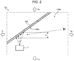
- the front windshield 102 is a portion ahead of the driver seat 104, and an image forming plane 5 may be disposed around the lower portion of the front windshield 102 in the up-down direction.
- the image forming plane 5 may be provided on the side of the interior surface 102a of the front windshield 102.
- a head-up display device (hereinafter described as a "HUD device") 1 provided in the dashboard 103 outputs a light beam to the image forming plane 5. Then, an image representing driving-related information is displayed on the image forming plane 5 so that the driver can obtain the driving-related information by looking at the image displayed on the image forming plane 5.
- HUD device head-up display device
- the configuration of the HUD device 1 according to the present embodiment will be described with reference to FIGS. 3 and 4 .
- the HUD device 1 includes a controller 11 and an optical processor 12.
- the controller 11 may include a microprocessor and a memory, such as a MPU/CPU, ASIC, ROM, and RAM.
- the controller 11 executes firmware stored in the memory in advance, for example, to generate an image signal related to driving-related information, and outputs the signal to the optical processor 12.
- the controller 11 may include a navigation information receiving unit 111, a vehicle speed information receiving unit 112, a preceding vehicle information receiving unit 113, and/or an image signal generation unit 116.
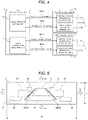
- the navigation information receiving unit 111 receives from a navigation system 2 an input of information about a guidance route and road information.
- the navigation information receiving unit 111 includes a guidance route receiving unit 114 that receives information about a guidance route from the navigation system 2, and a road information receiving unit 115 that receives road information from the navigation system 2.
- the navigation system 2 may include a guidance route setting unit 21 and/or a road information detection unit 22.
- the guidance route setting unit 21 is a section that sets a guidance route for guiding the vehicle 100 to an input destination, and outputs nearest route information INF11 and following route information INF12 to the guidance route receiving unit 114.
- the guidance route receiving unit 114 includes a nearest route information receiving unit 1141 that receives the nearest route information INF11 and a following route information receiving unit 1142 that receives the following route information INF12.
- the nearest route information INF11 is information (i.e., route guidance information) about the current or nearest guidance route along the travel route of the vehicle 100, and corresponds to "third information.”
- the following route information INF12 is information (i.e., route guidance information) about a guidance route following the nearest route information INF11 along the travel route of the vehicle 100, and corresponds to "fourth information.”
- the road information detection unit 22 is a section that detects information (i.e., route guidance information) about a road sign that is present on the route to be travelled by the vehicle 100, and outputs nearest road information INF21 and following road information INF22.
- the road information receiving unit 115 includes a nearest road information receiving unit 1151 that receives the nearest road information INF21 and a following road information receiving unit 1152 that receives the following road information INF22.
- the nearest road information INF21 may be information about the current or nearest road sign that is present along the travel route of the vehicle 100, and corresponds to "first information.”
- the following road information INF22 may be information about a road sign following (or to be presented later than) the nearest road information INF21 along the travel route of the vehicle 100, and corresponds to "second information.”
- the vehicle speed information receiving unit 112 may receive an input of information about the vehicle speed of the vehicle 100 from a vehicle speed detection unit 3 provided in the vehicle 100. It should be noted that there may be a case where the information about the vehicle speed from the vehicle speed detection unit 3 is input to the vehicle speed information receiving unit 112 via an ECU (Electronic Control Unit) of the vehicle 100.
- ECU Electronic Control Unit
- the preceding vehicle information receiving unit 113 receives from a preceding vehicle detection unit 4, which may include a device (for example, a radar, laser, and/or camera) provided in the vehicle 100 for detecting a preceding vehicle, information about the presence or absence of a preceding vehicle as well as, if the preceding vehicle is present, information about the inter-vehicle distance between the own vehicle 100 and the preceding vehicle.
- a preceding vehicle detection unit 4 may include a device (for example, a radar, laser, and/or camera) provided in the vehicle 100 for detecting a preceding vehicle, information about the presence or absence of a preceding vehicle as well as, if the preceding vehicle is present, information about the inter-vehicle distance between the own vehicle 100 and the preceding vehicle.
- the image signal generation unit 116 generates image signals e.g. based on the information received by the guidance route receiving unit 114, the road information receiving unit 115, the vehicle speed information receiving unit 112, and the preceding vehicle information receiving unit 113.
- the image signal generation unit 116 may generate a nearest route guidance image signal (i.e., a third image signal) based on the nearest route information INF11, and/or generates a following route guidance image signal (i.e., a fourth image signal) based on the following route information INF12.
- the image signal generation unit 116 generates a nearest road sign image signal (i.e., a first image signal) based on the nearest road information INF21, and generates a following road sign image signal (i.e., a second image signal) based on the following road information INF22.
- the image signal generation unit 116 generates a vehicle speed image signal based on the vehicle speed information, and generates a preceding vehicle image signal (i.e., a fifth image signal) based on the preceding vehicle information.
- the optical processor 12 may includes a modulation unit 121, a light source unit 122, and an output unit 123.
- the modulation unit 121 modulates a light beam output from the light source unit 122 according to each image signal sent from the image signal generation unit 116, thereby generating a video beam.
- the light source unit 122 may include LEDs (Light Emitting Diodes) or semiconductor laser devices, and outputs a light beam to the modulation unit 121.
- the output unit 123 outputs to the image forming plane 5 the video item generated through modulation by the modulation unit 121. It should be noted that the video beam output from the output unit 123 defines a display area on the image forming plane 5 for each image signal input to the optical processor 12.
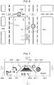
- FIG. 5 is a schematic plan view of the image forming plane 5 as seen from the side of the driver.
- the image forming plane 5 has a horizontally long rectangular shape with a horizontal width W longer than a height H.
- a video beam is output to the image forming plane 5 from the optical processor 12
- two strips of line segment objects OBJ51 and OBJ52 are displayed approximately in the central portion of the image forming plane 5 in the horizontal direction (i.e., vehicle width direction).
- the two strips of line segment objects OBJ51 and OBJ52 may always be displayed on the image forming plane 5 while the HUD device 1 is driven.
- the line segment object OBJ51 is a line segment object disposed on the left side of the line segment object OBJ52 and extending diagonally from the central portion in the vehicle width direction (i.e., left-right direction) to the left side in the direction from the upper portion to the lower portion.
- the line segment object OBJ51 shall be described as a "left line segment object OBJ51.”
- the line segment object OBJ52 is a line segment object disposed on the right side of the left line segment object OBJ51 with a gap therebetween, and extending diagonally from the central portion in the vehicle width direction (i.e., left-right direction) to the right side in the direction from the upper portion to the lower portion.
- the line segment object OBJ52 shall be referred to as a "right line segment object OBJ52.”
- the left line segment object OBJ51 and the right line segment object OBJ52 may be displayed or obliquely displayed such that the gap between them in the left-right direction gradually expands in the direction from the upper portion to the lower portion.
- An intermediate upper display area 53 is set in the upper portion of an area between the left line segment object OBJ51 and the right line segment object OBJ52, and an intermediate lower display area 54 is displayed in the lower portion thereof.
- a preceding vehicle object generated from a preceding vehicle image signal is displayed when a preceding vehicle has been detected with the preceding vehicle detection unit 4.
- an object related to the cruise control setting information is displayed.
- a left-side central display area 55 and a left-side upper display area 56 are set along the left line segment object OBJ51.
- the left-side central display area 55 is set below the left-side upper display area 56.
- a nearest route information object generated from a nearest route guidance image signal based on the nearest route information INF11 is displayed.
- a following route information object generated from a following route image signal based on the following route information INF12 is displayed.
- the size of the left-side central display area 55 may be set larger than the size of the left-side upper display area 56.
- a right-side central display area 57 and a right-side upper display area 58 are set along the right line segment object OBJ52.
- the right-side central display area 57 is set below the right-side upper display area 58.
- a nearest road sign information object generated from a nearest road sign image signal based on the nearest road information INF21 is displayed.
- a following road sign information object generated from a following road sign image signal based on the following road information INF22 is displayed.
- the size of the right-side central display area 57 may be set larger than the size of the right-side upper display area 58.
- a right-side lower display area 59 may be set below the right-side central display area 57.
- a vehicle speed information object generated from a vehicle speed image signal based on the vehicle speed information from the vehicle speed detection unit 3 may be displayed. The driver can check the speed of his/her own vehicle 100 by looking at the right-side lower display area 59.
- a left-side first lower display area 60 and a left-side second lower display area 61 may be set below the left-side central display area 55.
- the left-side first lower display area 60 may be set below the left-side second lower display area 61.
- an object related to the estimated arrival time of the vehicle 100 at the destination which has been generated from an image signal based on the information from the navigation system 2 and the vehicle speed detection unit 3, may be displayed.
- an information object related to the moving direction at an intersection related to the nearest route information INF11 is displayed.
- FIG. 6 is a schematic view illustrating the travel route and the surrounding circumstance of the vehicle 100
- FIG. 7 is a schematic view illustrating the various objects OBJ51 to OBJ61 displayed on the image forming plane 5 at the current places illustrated in FIG. 6 .
- the vehicle 100 is travelling straight along a road STR1 with two lanes on each side (indicated by the arrow A1) .
- a preceding vehicle 200 is travelling ahead of the own vehicle 100 in the same direction as the own vehicle 100.
- a road sign which indicates that the speed limit on the road STR1 is e.g. 60 km/h, is built on the side of the road STR1.
- the HUD device 1 receives from the navigation system 2 information to the effect that the speed limit on the road STR1 is 60 km/h.
- the HUD device 1 also receives from the preceding vehicle detection unit 4 provided in the vehicle 100 information to the effect that the preceding vehicle 200 is present and information about the inter-vehicle distance between the own vehicle 100 and the preceding vehicle 200. Further, the HUD device 1 also receives from the vehicle speed detection unit 3 information about the vehicle speed of the own vehicle 100.
- the vehicle 100 is to turn left at an intersection JNC1 that is about 450 m ahead so as to enter a road STR2 (indicated by the arrow A2), and to turn left at an intersection JNC2 on the road STR2 so as to enter a road STR3 (indicated by the arrow A3) .
- the navigation system 2 sends information about such route guidance to the HUD device 1.
- the navigation system 2 sends to the HUD device 1 information to the effect that the speed limit on the road STR2 is e.g. 40 km/h.
- the information to the effect that the vehicle 100 is to turn left as indicated by the arrow A2 corresponds to the "nearest route information INF11," and the information to the effect that the vehicle 100 is to turn left as indicated by the arrow A3 corresponds to the "following route information INF12."
- the information to the effect that the speed limit on the road STR1 is 60 km/h corresponds to the "nearest road information INF21”
- the information to the effect that the speed limit on the road STR2 is 40 km/h corresponds to the "following road information INF22.”
- the information to the effect that the preceding vehicle 200 is present as detected by the preceding vehicle detection unit 4 and the information about the inter-vehicle distance between the own vehicle 100 and the preceding vehicle 200 corresponds to the "preceding vehicle information.”
- various objects OBJ51 to OBJ61 such as those illustrated in FIG. 7 are displayed on the image forming plane 5 of the vehicle 100 that is traveling straight along the road STR1 as indicated by the arrow A1.
- the left line segment object OBJ51 and the right line segment object OBJ52 are displayed in the central portion of the image forming plane 5 in the left-right direction as described above.
- Such line segment objects OBJ51 and OBJ52 remind the driver of demarcation lines on the opposite sides of the driving lane.
- a preceding vehicle information object OBJ53 is displayed in the intermediate upper display area 53 between the left line segment object OBJ51 and the right line segment object OBJ52.
- the preceding vehicle information object OBJ53 is an object indicating information to the effect that the preceding vehicle 200 is present and information about the inter-vehicle distance between the own vehicle 100 and the preceding vehicle 200, and corresponds to a "fifth information object.”
- a set vehicle speed information object OBJ54 may be displayed in the intermediate lower display area 54 below the intermediate upper display area 53 in which the preceding vehicle information object OBJ53 is displayed.
- the set vehicle speed information object OBJ54 is an object indicating various setting conditions of cruise control, such as the set speed.
- a route guidance information object OBJ55 may displayed in the left-side central display area 55 on the left side of the left line segment object OBJ51.
- the route guidance information object OBJ55 is an object generated from an image signal based on the nearest route information INF11, and corresponds to a "third information object.”
- a route guidance information object OBJ56 may be displayed in the left-side upper display area 56 on the left side of the left line segment object OBJ51 and above the left-side central display area 55.
- the route guidance information object OBJ56 is an object generated from an image signal based on the following route information INF12, and corresponds to a "fourth information object.”
- each of the route guidance information object OBJ55 and the route guidance information object OBJ56 includes straight lines and curved lines, but the line widths of the line segments included in the route guidance information object OBJ55 are thicker than those of the route guidance information object OBJ56.
- a road sign information object OBJ57 may be displayed in the right-side central display area 57 on the right side of the right line segment object OBJ52.
- the road sign information object OBJ57 may be an object generated from an image signal based on the nearest road information INF21, and corresponds to a "first information object.”
- a road sign information object OBJ58 is displayed in the right-side upper display area 58 on the right side of the right line segment object OBJ52 and above the right-side central display area 57.
- the road sign information object OBJ58 is an object generated from an image signal based on the following road information INF22, and corresponds to a "second information object.”
- each of the road sign information object OBJ57 and the road sign information object OBJ58 may include curved lines, and the line widths of the line segments included in the road sign information object OBJ57 may be thicker than those of the road sign information object OBJ58.
- a vehicle speed information object OBJ59 may be displayed in the right-side lower display area 59 below the right-side central display area 57.
- the vehicle speed information object OBJ59 is an object generated from an image signal based on the vehicle speed information from the vehicle speed detection unit 3.
- the size of the vehicle speed information object OBJ59 in the height direction and the left-right direction is set larger than that of the set vehicle speed information object OBJ54, and the vehicle speed information object OBJ59 includes line segments thicker than those of the set vehicle speed information object OBJ54 so that the driver can easily see the vehicle speed information object OBJ59.
- An estimated arrival time information object OBJ60 may be displayed in the left-side first lower display area 60 below the left-side central display area 55.
- the estimated arrival time information object OBJ60 is an object indicating the estimated arrival time of the vehicle 100 at the destination based on the information from the navigation system 2 and the vehicle speed detection unit 3.
- a lane information object OBJ61 may be displayed in the left-side second lower display area 61 between the left-side central display area 55 and the left-side first lower display area 60.
- the lane information object OBJ61 is an object indicating information about the moving direction at the nearest intersection JNC1 where the vehicle 100 is to turn left first.
- the left line segment object OBJ51 and the right line segment object OBJ52 are displayed on the image forming plane 5.
- the left line segment object OBJ51 and the right line segment object OBJ52 are displayed such that the gap between them gradually expands in the direction from the upper portion to the lower portion.
- the line segment objects OBJ51 and OBJ52 can remind the driver of a driving lane on the image forming plane 5 with a sense of perspective.
- the road sign information object OBJ57 that appears first along the travel route and the road sign information object OBJ58 that appears next along the travel route are both disposed along the right line segment object OBJ52, and the road sign information object OBJ57 is displayed below the road sign information object OBJ58. Therefore, with the HUD device 1, it is possible to allow the driver to intuitively recognize that the road information represented by the road sign information object OBJ57 is the preceding information, and the road information represented by the road sign information object OBJ58 is the following information, together with the left line segment object OBJ51 and the right line segment object OBJ52 that remind the driver of the driving lane.
- the HUD device 1 it is possible to allow the driver to intuitively recognize the two information objects (i.e., the road sign information object OBJ57 and the road sign information object OBJ58) sequentially along the travel route of the vehicle 100 while projecting a video onto the image forming plane 5 that has a length in the vertical direction shorter than a length in the horizontal direction.
- the two information objects i.e., the road sign information object OBJ57 and the road sign information object OBJ58
- the road sign information object OBJ57 is displayed in a form with higher visibility than the road sign information object OBJ58 on the image forming plane 5.
- the driver's attention more to the road sign information object OBJ57 with relatively higher visibility is possible to direct the driver's attention more to the road sign information object OBJ57 with relatively higher visibility.
- the road sign information object OBJ57 is displayed with a larger size in the height direction and the horizontal direction than the road sign information object OBJ58 on the image forming plane 5.
- the road sign information object OBJ57 has a larger size than the road sign information object OBJ58, it is possible to allow the driver to feel a sense of perspective even more.
- the road sign information object OBJ57 includes line segments with thicker line widths than the road sign information object OBJ58 on the image forming plane 5.
- the road sign information object OBJ57 includes line segments with thicker line widths.
- the route guidance information object OBJ55 and the route guidance information object OBJ56 are also displayed on the image forming plane 5.
- the driver it is possible to allow the driver to recognize more pieces of information via the image forming plane 5.
- the route guidance information object OBJ55 related to the route guidance information that appears first along the travel route and the route guidance information object OBJ56 related to the route guidance information that appears next along the travel route are both disposed along the left line segment object OBJ51, and the route guidance information object OBJ55 is displayed below the route guidance information object OBJ56. Therefore, with the HUD device 1, it is possible to allow the driver to intuitively recognize that the route guidance information represented by the route guidance information object OBJ55 is the preceding information, and the route guidance information represented by the route guidance information object OBJ56 is the following information.
- the information represented by the road sign information object OBJ57 and the information represented by the road sign information object OBJ58 are information related to road signs of the same type.
- the driver to, upon looking at the road sign information object OBJ57 and the road sign information object OBJ58, intuitively recognize the transition between the pieces of road sign information of the same type along the travel route.
- the information represented by the route guidance information object OBJ55 and the information represented by the route guidance information object OBJ56 are information related to route guidance of the same type, it is possible to allow the driver to, upon looking at the route guidance information object OBJ55 and the route guidance information object OBJ56, intuitively recognize the transition between the pieces of route guidance information of the same type along the travel route.
- the vehicle 100 is a right-hand drive vehicle, and the road sign information object OBJ57 and the road sign information object OBJ58 are displayed around the right part of the image forming plane 5.
- the driver it is possible to intuitively recognize the road sign information by displaying the road sign information object OBJ57 and the road sign information object OBJ58 on the image forming plane 5 at corresponding positions along the direction in which the actual road signs are provided.
- the road sign information object OBJ57 and the road sign information object OBJ58 may be displayed around the left part of the image forming plane 5. Then, it is possible to allow the driver to intuitively recognize the road sign information by displaying the road sign information object OBJ57 and the road sign information object OBJ58 on the image forming plane 5 at corresponding positions along the direction in which the actual road signs are provided.
- the preceding vehicle information object OBJ53 representing information about the preceding vehicle 200 is also displayed.
- the preceding vehicle information object OBJ53 is displayed at a position between the left line segment object OBJ51 and the right line segment object OBJ52.
- the HUD device 1 As described above, with the HUD device 1 according to the present embodiment, it is possible to allow the driver to intuitively recognize the plurality of objects OBJ55 to OBJ58 sequentially along the travel route of the vehicle 100 while projecting a video onto the image forming plane 5 that has a length in the vertical direction shorter than a length in the horizontal direction.
- the two road sign information objects OBJ57 and OBJ58 and the two route guidance information objects OBJ55 and OBJ56 are displayed on the image forming plane 5, but the present invention is not limited thereto.
- the left line segment object and the right line segment object be displayed and the aforementioned objects be arranged in the same pattern as that of the aforementioned embodiment so that the driver can recognize the information with a sense of perspective.
- the objects OBJ55 and OBJ56 displayed on the left side of the left line segment object OBJ51 are objects related to information of the same type
- the objects OBJ57 and OBJ58 displayed on the right side of the right line segment object OBJ52 are objects related to information of the same type, but the present invention is not limited thereto.
- the preceding vehicle information object OBJ53 is displayed between the left line segment object OBJ51 and the right line segment object OBJ52, but in the present invention, the display of the preceding vehicle information object is not essential. Likewise, the display of the objects OBJ59, OBJ60, and OBJ61 is not essential, either.
- a front windshield projection type in which the image forming plane 5 is provided on the front windshield 102 is adopted as an example, but in the present invention, a combiner type may also be adopted. That is, it is also possible to adopt a type in which a projection plane onto which a video is projected is provided between the front windshield and the driver.
- the nearest information and the following information are obtained for each of the road sign information and the route guidance information so that the objects OBJ55 to OBJ58 are displayed on the image forming plane 5.
- the types of the nearest driving-related information and the following driving-related information are not limited thereto.
- the road sign information object OBJ57 and the road sign information object OBJ58 are displayed so as not to overlap each other, and likewise, the route guidance information object OBJ55 and the route guidance information object OBJ56 are displayed so as not to overlap each other.
- the present invention is not limited thereto, and the nearest information object and the following information object may be displayed so as to partially overlap each other. In such a case, however, it is desirable to display the nearest information object on top of the following information object.
- the color of the information object representing the nearest driving-related information is set different from the color of the information object representing the following driving-related information.
- the color of the information object representing the nearest driving-related information may be set different from the color of the information object representing the following driving-related information.
- the object related to the nearest driving-related information may be displayed in color, while the object related to the following driving-related information may be displayed in monochrome.
- each of the left line segment object OBJ51 and the right line segment object OBJ52 is represented by a straight line.
- each of such line segment objects may be represented by a curved line.
Landscapes
- Engineering & Computer Science (AREA)
- Mechanical Engineering (AREA)
- Chemical & Material Sciences (AREA)
- Combustion & Propulsion (AREA)
- Transportation (AREA)
- Physics & Mathematics (AREA)
- General Physics & Mathematics (AREA)
- Theoretical Computer Science (AREA)
- Optics & Photonics (AREA)
- Computer Hardware Design (AREA)
- Traffic Control Systems (AREA)
- Instrument Panels (AREA)
- Navigation (AREA)
- Fittings On The Vehicle Exterior For Carrying Loads, And Devices For Holding Or Mounting Articles (AREA)
Abstract
Description
- The present invention relates to a head-up display device and a vehicle.
- A head-up display device is a device that projects objects related to various types of driving-related information onto an image forming plane ahead of a driver seat. A vehicle with a head-up display device allows a driver to recognize various types of driving-related information without requiring him/her to look away from his/her viewpoint.
- Patent Literature 1 discloses a head-up display device that projects objects related to information on external factors outside a vehicle, such as a road sign and route guidance, onto the upper portion of an image forming plane, and projects objects related to information on the own vehicle, such as the vehicle speed and ON/OFF of cruise control, onto the lower portion of the image forming plane.
- [Patent Literature 1]
Japanese Patent No. 6354633 - However, the image forming plane onto which the head-up display device projects objects related to various types of information should have a shape with a short length in the up-down direction so as not to obstruct the line of vision of the driver looking ahead of the vehicle. Therefore, with the head-up display device, it would be difficult to arrange a plurality of objects, such as sign guidance and route guidance, in the up-down direction of the image forming plane sequentially along the travel route of the vehicle, unlike with a navigation device. Accordingly, with the conventional head-up display device, it has been difficult to allow a driver to intuitively recognize the nearest information and the following information sequentially along the travel route of the vehicle.
- The present invention has been made to solve the foregoing problem, and it is an object of the present invention to allow a driver to intuitively recognize a plurality of objects sequentially along a travel route of a vehicle, particularly while projecting a video onto an image forming plane that has a length in the vertical direction shorter than a length in the horizontal direction.
- A head-up display device according to an aspect of the present invention is a device for projecting driving-related information onto an image forming plane provided ahead of a driver seat, including a controller and an optical processor. The controller receives the driving-related information, and generates an image signal from the received driving-related information. The optical processor obtains the image signal from the controller, and outputs a light beam to the image forming plane.
- The controller includes a first information receiving unit, a second information receiving unit, and an image signal generation unit. The first information receiving unit receives first information that is the current or nearest driving-related information along a travel route of a vehicle. The second information receiving unit receives second information that is the driving-related information following the first information. The image signal generation unit generates a first image signal based on the first information and generates a second image signal based on the second information.
- The optical processor outputs a light beam to the image forming plane as seen in plan view from the driver seat so as to display a left line segment object, a right line segment object, a first information object, and a second information object. The left line segment object is an object extending diagonally from a central portion in a left-right direction to a left side in a direction from an upper portion to a lower portion. The right line segment object is an object disposed on a right side of the left line segment object and extending diagonally from the central portion to a right side in the direction from the upper portion to the lower portion. The first information object is an object generated from the first image signal and disposed at a position along one of the left line segment object and the right line segment object on an outer side of the one of the line segment objects in the left-right direction. The second information object is an object generated from the second image signal and disposed at a position along the one of the line segment objects on the outer side of the one of the line segment objects in the left-right direction, and diagonally above the first information object.
- With the head-up display device according to the aforementioned aspect, the left line segment object and the right line segment object are displayed on the image forming plane, and the left line segment object and the right line segment object are displayed such that the gap between them gradually expands in the direction from the upper portion to the lower portion. Thus, such line segment objects can remind the driver of a driving lane on the image forming plane with a sense of perspective.
- In addition, with the head-up display device according to the aforementioned aspect, the first information object related to the first information that appears first along the travel route, and the second object related to the second information that appears next along the travel route are both disposed along one of the aforementioned line segment objects, and the first information object is displayed below the second information object.
- Therefore, with the head-up display device according to the aforementioned aspect, it is possible to allow the driver to intuitively recognize that the first information represented by the first information object is the preceding information, and the second information represented by the second information object is the following information, together with the left line segment object and right line segment object that remind the driver of the driving lane.
- Particularly, with the head-up display device according to the aforementioned aspect, it is possible to allow the driver to intuitively recognize a plurality of information objects (i.e., the first information object and the second information object) sequentially along the travel route of the vehicle while projecting a video onto the image forming plane that has a length in the vertical direction shorter than a length in the horizontal direction.
- In the head-up display device according to the aforementioned aspect, the image signal generation unit may generate the first image signal and the second image signal so that the first information object is displayed in a form with higher visibility for a driver of the vehicle than the second information object on the image forming plane.
- With the head-up display device according to the aforementioned aspect, since the first information object is displayed in a form with higher visibility than the second information object on the image forming plane, it is possible to direct the driver's attention more to the first information object with relatively higher visibility.
- In the head-up display device according to the aforementioned aspect, the image signal generation unit may generate the first image signal and the second image signal so that the first information object is displayed with a larger size than the second information object on the image forming plane.
- With the head-up display device according to the aforementioned aspect, since the first information object is displayed with a larger size than the second information object on the image forming plane, it is possible to direct the driver's attention more to the first information object with a larger size. In addition, as the first information object has a larger size than the second information object, it is possible to allow the driver to feel a sense of perspective even more.
- In the head-up display device according to the aforementioned aspect, each of the first information object and the second information object may include at least one of a line segment of a straight line and a line segment of a curved line, and the image signal generation unit may generate the first image signal and the second image signal so that the line segment of the first information object is displayed with a thicker line width than the line segment of the second information object on the image forming plane.
- With the head-up display device according to the aforementioned aspect, since the first information object includes line segments with thicker line widths than the second information object on the image forming plane, it is possible to direct the driver's attention more to the first information including line segments with thicker line widths.
- In the head-up display device according to the aforementioned aspect, the controller may further include a third information receiving unit that receives third information that is the current or nearest driving-related information along the travel route of the vehicle and is the driving-related information of a type different from the first information, and a fourth information receiving unit that receives fourth information that is the driving-related information following the third information, the image signal generation unit may generate a third image signal based on the third information and also generate a fourth image signal based on the fourth information, and the optical processor may output a light beam to the image forming plane as seen in plan view from the driver seat so as to display the following: a third information object that is an object generated from the third image signal and disposed at a position along the other line segment object different from the one of the left line segment object and the right line segment object on an outer side of the other line segment object in the left-right direction, and a fourth information object that is an object generated from the fourth image signal and disposed at a position along the other line segment object on the outer side of the other line segment object in the left-right direction, and diagonally above the third information object.
- With the head-up display device according to the aforementioned aspect, the third information object and the fourth information object are also displayed on the image forming plane in addition to the first information object and the second information object. Thus, it is possible to allow the driver to recognize more pieces of information via the image forming plane.
- With the head-up display device according to the aforementioned aspect, the third information object related to the third information that appears first along the travel route and the fourth object related to the fourth information that appears next along the travel route are both disposed along the other line segment object, and the third information object is displayed below the fourth information object.
- Therefore, with the head-up display device according to the aforementioned aspect, it is possible to allow the driver to intuitively recognize that the third information represented by the third information object is the preceding information, and the fourth information represented by the fourth information object is the following information, as with the relationship between the first information object and the second information object.
- In the head-up display device according to the aforementioned aspect, the first information and the second information may be the driving-related information of the same type, and the third information and the fourth information may be the driving-related information of the same type.
- With the head-up display device according to the aforementioned aspect, since the first information and the second information are the information of the same type, it is possible to allow the driver to, upon looking at the first information object and the second information object, intuitively recognize the transition between the pieces of information of the same type along the travel route. Likewise, since the third information and the fourth information are the information of the same type, it is possible to allow the driver to, upon looking at the third information object and the fourth information object, intuitively recognize the transition between the pieces of information of the same type along the travel route.
- With the head-up display device according to the aforementioned aspect, the first information and the second information may be road sign information, the third information and the fourth information may be route guidance information, and when the vehicle is a right-hand drive vehicle, the one of the line segment objects may be the right line segment object, and the other line segment object may be the left line segment object, while when the vehicle is a left-hand drive vehicle, the one of the line segment objects may be the left line segment object, and the other line segment object may be the right line segment object.
- With the head-up display device according to the aforementioned aspect, when the vehicle is a right-hand drive vehicle, the first information object and the second information object each representing the road sign information are displayed around the right part of the image forming plane. Thus, it is possible to allow the driver to intuitively recognize the road sign information by displaying the first information object and the second information object on the image forming plane at corresponding positions along the direction in which the actual road signs are provided. Meanwhile, when the vehicle is a left-hand drive vehicle, the first information object and the second information object each representing the road sign information are displayed around the left part of the image forming plane. Thus, it is also possible to allow the driver to intuitively recognize the road sign information by displaying the first information object and the second information object on the image forming plane at corresponding positions along the direction in which the actual road signs are provided.
- In the head-up display device according to the aforementioned aspect, the controller may further include a fifth information receiving unit that receives fifth information about presence or absence of a preceding vehicle as well as, if the preceding vehicle is present, an inter-vehicle distance from the preceding vehicle, the image signal generation unit may also generate a fifth image signal based on the fifth information, and the optical processor may output a light beam to the image forming plane as seen in plan view from the driver seat so that a fifth information object is also displayed, the fifth information object being an object generated from the fifth image signal and disposed at a position between the left line segment object and the right line segment object.
- With the head-up display device according to the aforementioned aspect, the fifth information object representing information about a preceding vehicle is also displayed. Thus, it is possible to allow the driver to, upon looking at the image forming plane, also recognize the information about the preceding vehicle. In addition, with the head-up display device according to the aforementioned aspect, the fifth information object is displayed at a position between the left line segment object and the right line segment object. Thus, it is possible to allow the driver to intuitively recognize the information about the preceding vehicle in the driving lane where the driver's own vehicle is traveling.
- With the head-up display device according to each of the aforementioned aspects, it is possible to allow a driver to intuitively recognize a plurality of objects sequentially along a travel route of a vehicle, particularly while projecting a video onto an image forming plane that has a length in the vertical direction shorter than a length in the horizontal direction.
-
-
FIG. 1 is a view illustrating the configuration of the interior of a vehicle cabin of a vehicle to which a head-up display device according to an embodiment of the present invention is applied. -
FIG. 2 is a schematic view illustrating a head-up display device and an image forming plane. -
FIG. 3 is a block diagram illustrating the configuration of the head-up display device. -
FIG. 4 is a block diagram illustrating the detailed configuration of a guidance route receiving unit and a road information receiving unit. -
FIG. 5 is a schematic view illustrating the arrangement pattern of display areas of various objects on the image forming plane. -
FIG. 6 is a schematic view illustrating the travel route of the vehicle. -
FIG. 7 is a schematic view illustrating various objects displayed on the image forming plane. - Hereinafter, an embodiment of the present invention will be described with reference to the drawings. It should be noted that the embodiment described below is only an example of the present invention, and the present invention is not limited thereto except its inherent configuration. All of the features as shown in the drawings may not necessarily be essential.
- Described below with reference to
FIGS. 1 and2 is the configuration of the interior of avehicle cabin 100a of avehicle 100 to which a head-up display device according to an embodiment is applied. - As illustrated in
FIG. 1 , thevehicle 100 may be a right-hand drive vehicle in which asteering wheel 101 is provided on the right side in the vehicle width direction. Adashboard 103 is provided ahead of thesteering wheel 101, and afront windshield 102 is provided in a state upwardly extending from the front end portion of thedashboard 103. - A
driver seat 104 is provided behind thesteering wheel 101, and apassenger seat 105 may be provided on the left side of thedriver seat 104. - As illustrated in
FIG. 1 , thefront windshield 102 is a portion ahead of thedriver seat 104, and animage forming plane 5 may be disposed around the lower portion of thefront windshield 102 in the up-down direction. As illustrated inFIG. 2 , theimage forming plane 5 may be provided on the side of theinterior surface 102a of thefront windshield 102. A head-up display device (hereinafter described as a "HUD device") 1 provided in thedashboard 103 outputs a light beam to theimage forming plane 5. Then, an image representing driving-related information is displayed on theimage forming plane 5 so that the driver can obtain the driving-related information by looking at the image displayed on theimage forming plane 5. - The configuration of the HUD device 1 according to the present embodiment will be described with reference to
FIGS. 3 and4 . - As illustrated in
FIG. 3 , the HUD device 1 includes acontroller 11 and anoptical processor 12. Thecontroller 11 may include a microprocessor and a memory, such as a MPU/CPU, ASIC, ROM, and RAM. Thecontroller 11 executes firmware stored in the memory in advance, for example, to generate an image signal related to driving-related information, and outputs the signal to theoptical processor 12. - The
controller 11 may include a navigationinformation receiving unit 111, a vehicle speedinformation receiving unit 112, a preceding vehicleinformation receiving unit 113, and/or an imagesignal generation unit 116. The navigationinformation receiving unit 111 receives from anavigation system 2 an input of information about a guidance route and road information. The navigationinformation receiving unit 111 includes a guidanceroute receiving unit 114 that receives information about a guidance route from thenavigation system 2, and a roadinformation receiving unit 115 that receives road information from thenavigation system 2. - As illustrated in
FIG. 4 , thenavigation system 2 may include a guidanceroute setting unit 21 and/or a roadinformation detection unit 22. The guidanceroute setting unit 21 is a section that sets a guidance route for guiding thevehicle 100 to an input destination, and outputs nearest route information INF11 and following route information INF12 to the guidanceroute receiving unit 114. The guidanceroute receiving unit 114 includes a nearest routeinformation receiving unit 1141 that receives the nearest route information INF11 and a following routeinformation receiving unit 1142 that receives the following route information INF12. - Herein, the nearest route information INF11 is information (i.e., route guidance information) about the current or nearest guidance route along the travel route of the
vehicle 100, and corresponds to "third information." The following route information INF12 is information (i.e., route guidance information) about a guidance route following the nearest route information INF11 along the travel route of thevehicle 100, and corresponds to "fourth information." - As illustrated in
FIG. 4 , the roadinformation detection unit 22 is a section that detects information (i.e., route guidance information) about a road sign that is present on the route to be travelled by thevehicle 100, and outputs nearest road information INF21 and following road information INF22. The roadinformation receiving unit 115 includes a nearest roadinformation receiving unit 1151 that receives the nearest road information INF21 and a following roadinformation receiving unit 1152 that receives the following road information INF22. - The nearest road information INF21 may be information about the current or nearest road sign that is present along the travel route of the
vehicle 100, and corresponds to "first information." The following road information INF22 may be information about a road sign following (or to be presented later than) the nearest road information INF21 along the travel route of thevehicle 100, and corresponds to "second information." - Referring back to
FIG. 3 , the vehicle speedinformation receiving unit 112 may receive an input of information about the vehicle speed of thevehicle 100 from a vehiclespeed detection unit 3 provided in thevehicle 100. It should be noted that there may be a case where the information about the vehicle speed from the vehiclespeed detection unit 3 is input to the vehicle speedinformation receiving unit 112 via an ECU (Electronic Control Unit) of thevehicle 100. - The preceding vehicle
information receiving unit 113 receives from a precedingvehicle detection unit 4, which may include a device (for example, a radar, laser, and/or camera) provided in thevehicle 100 for detecting a preceding vehicle, information about the presence or absence of a preceding vehicle as well as, if the preceding vehicle is present, information about the inter-vehicle distance between theown vehicle 100 and the preceding vehicle. - It should be noted that the aforementioned information output from the preceding
vehicle detection unit 4 corresponds to "fifth information." - The image
signal generation unit 116 generates image signals e.g. based on the information received by the guidanceroute receiving unit 114, the roadinformation receiving unit 115, the vehicle speedinformation receiving unit 112, and the preceding vehicleinformation receiving unit 113. - Particularly, the image
signal generation unit 116 may generate a nearest route guidance image signal (i.e., a third image signal) based on the nearest route information INF11, and/or generates a following route guidance image signal (i.e., a fourth image signal) based on the following route information INF12. In addition, the imagesignal generation unit 116 generates a nearest road sign image signal (i.e., a first image signal) based on the nearest road information INF21, and generates a following road sign image signal (i.e., a second image signal) based on the following road information INF22. - Further particularly, the image
signal generation unit 116 generates a vehicle speed image signal based on the vehicle speed information, and generates a preceding vehicle image signal (i.e., a fifth image signal) based on the preceding vehicle information. - The
optical processor 12 may includes amodulation unit 121, alight source unit 122, and anoutput unit 123. Themodulation unit 121 modulates a light beam output from thelight source unit 122 according to each image signal sent from the imagesignal generation unit 116, thereby generating a video beam. - The
light source unit 122 may include LEDs (Light Emitting Diodes) or semiconductor laser devices, and outputs a light beam to themodulation unit 121. Theoutput unit 123 outputs to theimage forming plane 5 the video item generated through modulation by themodulation unit 121. It should be noted that the video beam output from theoutput unit 123 defines a display area on theimage forming plane 5 for each image signal input to theoptical processor 12. - An arrangement pattern of display areas of various objects on the
image forming plane 5 will be described with reference toFIG. 5. FIG. 5 is a schematic plan view of theimage forming plane 5 as seen from the side of the driver. - As illustrated in
FIG. 5 , theimage forming plane 5 has a horizontally long rectangular shape with a horizontal width W longer than a height H. When a video beam is output to theimage forming plane 5 from theoptical processor 12, two strips of line segment objects OBJ51 and OBJ52 are displayed approximately in the central portion of theimage forming plane 5 in the horizontal direction (i.e., vehicle width direction). - The two strips of line segment objects OBJ51 and OBJ52 may always be displayed on the
image forming plane 5 while the HUD device 1 is driven. - The line segment object OBJ51 is a line segment object disposed on the left side of the line segment object OBJ52 and extending diagonally from the central portion in the vehicle width direction (i.e., left-right direction) to the left side in the direction from the upper portion to the lower portion. Hereinafter, the line segment object OBJ51 shall be described as a "left line segment object OBJ51."
- The line segment object OBJ52 is a line segment object disposed on the right side of the left line segment object OBJ51 with a gap therebetween, and extending diagonally from the central portion in the vehicle width direction (i.e., left-right direction) to the right side in the direction from the upper portion to the lower portion. Hereinafter, the line segment object OBJ52 shall be referred to as a "right line segment object OBJ52."
- The left line segment object OBJ51 and the right line segment object OBJ52 may be displayed or obliquely displayed such that the gap between them in the left-right direction gradually expands in the direction from the upper portion to the lower portion.
- An intermediate
upper display area 53 is set in the upper portion of an area between the left line segment object OBJ51 and the right line segment object OBJ52, and an intermediate lower display area 54 is displayed in the lower portion thereof. In the intermediateupper display area 53, a preceding vehicle object generated from a preceding vehicle image signal is displayed when a preceding vehicle has been detected with the precedingvehicle detection unit 4. In the intermediate lower display area 54, an object related to the cruise control setting information is displayed. - On the left side of the left line segment object OBJ51, a left-side
central display area 55 and a left-sideupper display area 56 are set along the left line segment object OBJ51. The left-sidecentral display area 55 is set below the left-sideupper display area 56. In the left-sidecentral display area 55, a nearest route information object generated from a nearest route guidance image signal based on the nearest route information INF11 is displayed. In the left-sideupper display area 56, a following route information object generated from a following route image signal based on the following route information INF12 is displayed. - Herein, the size of the left-side
central display area 55 may be set larger than the size of the left-sideupper display area 56. - On the right side of the right line segment object OBJ52, a right-side
central display area 57 and a right-sideupper display area 58 are set along the right line segment object OBJ52. The right-sidecentral display area 57 is set below the right-sideupper display area 58. In the right-sidecentral display area 57, a nearest road sign information object generated from a nearest road sign image signal based on the nearest road information INF21 is displayed. In the right-sideupper display area 58, a following road sign information object generated from a following road sign image signal based on the following road information INF22 is displayed. - Herein, the size of the right-side
central display area 57 may be set larger than the size of the right-sideupper display area 58. - A right-side
lower display area 59 may be set below the right-sidecentral display area 57. In the right-sidelower display area 59, a vehicle speed information object generated from a vehicle speed image signal based on the vehicle speed information from the vehiclespeed detection unit 3 may be displayed. The driver can check the speed of his/herown vehicle 100 by looking at the right-sidelower display area 59. - A left-side first
lower display area 60 and a left-side secondlower display area 61 may be set below the left-sidecentral display area 55. The left-side firstlower display area 60 may be set below the left-side secondlower display area 61. In the left-side firstlower display area 60, an object related to the estimated arrival time of thevehicle 100 at the destination, which has been generated from an image signal based on the information from thenavigation system 2 and the vehiclespeed detection unit 3, may be displayed. In the left-side secondlower display area 61, an information object related to the moving direction at an intersection related to the nearest route information INF11 is displayed. - Display examples of various objects OBJ51 to OBJ61 on the
image forming plane 5 will be described with reference toFIGS. 6 and 7. FIG. 6 is a schematic view illustrating the travel route and the surrounding circumstance of thevehicle 100, andFIG. 7 is a schematic view illustrating the various objects OBJ51 to OBJ61 displayed on theimage forming plane 5 at the current places illustrated inFIG. 6 . - As illustrated in
FIG. 6 , thevehicle 100 is travelling straight along a road STR1 with two lanes on each side (indicated by the arrow A1) . In addition, a precedingvehicle 200 is travelling ahead of theown vehicle 100 in the same direction as theown vehicle 100. A road sign, which indicates that the speed limit on the road STR1 is e.g. 60 km/h, is built on the side of the road STR1. In thevehicle 100, the HUD device 1 receives from thenavigation system 2 information to the effect that the speed limit on the road STR1 is 60 km/h. In addition, the HUD device 1 also receives from the precedingvehicle detection unit 4 provided in thevehicle 100 information to the effect that the precedingvehicle 200 is present and information about the inter-vehicle distance between theown vehicle 100 and the precedingvehicle 200. Further, the HUD device 1 also receives from the vehiclespeed detection unit 3 information about the vehicle speed of theown vehicle 100. - The
vehicle 100 is to turn left at an intersection JNC1 that is about 450 m ahead so as to enter a road STR2 (indicated by the arrow A2), and to turn left at an intersection JNC2 on the road STR2 so as to enter a road STR3 (indicated by the arrow A3) . Thenavigation system 2 sends information about such route guidance to the HUD device 1. - It should be noted that the
navigation system 2 sends to the HUD device 1 information to the effect that the speed limit on the road STR2 is e.g. 40 km/h. - In the example illustrated in
FIG. 6 , the information to the effect that thevehicle 100 is to turn left as indicated by the arrow A2 corresponds to the "nearest route information INF11," and the information to the effect that thevehicle 100 is to turn left as indicated by the arrow A3 corresponds to the "following route information INF12." In addition, the information to the effect that the speed limit on the road STR1 is 60 km/h corresponds to the "nearest road information INF21," and the information to the effect that the speed limit on the road STR2 is 40 km/h corresponds to the "following road information INF22." Further, the information to the effect that the precedingvehicle 200 is present as detected by the precedingvehicle detection unit 4 and the information about the inter-vehicle distance between theown vehicle 100 and the precedingvehicle 200 corresponds to the "preceding vehicle information." - In such a circumstance, various objects OBJ51 to OBJ61 such as those illustrated in
FIG. 7 are displayed on theimage forming plane 5 of thevehicle 100 that is traveling straight along the road STR1 as indicated by the arrow A1. Specifically, the left line segment object OBJ51 and the right line segment object OBJ52 are displayed in the central portion of theimage forming plane 5 in the left-right direction as described above. Such line segment objects OBJ51 and OBJ52 remind the driver of demarcation lines on the opposite sides of the driving lane. - A preceding vehicle information object OBJ53 is displayed in the intermediate
upper display area 53 between the left line segment object OBJ51 and the right line segment object OBJ52. The preceding vehicle information object OBJ53 is an object indicating information to the effect that the precedingvehicle 200 is present and information about the inter-vehicle distance between theown vehicle 100 and the precedingvehicle 200, and corresponds to a "fifth information object." - A set vehicle speed information object OBJ54 may be displayed in the intermediate lower display area 54 below the intermediate
upper display area 53 in which the preceding vehicle information object OBJ53 is displayed. - The set vehicle speed information object OBJ54 is an object indicating various setting conditions of cruise control, such as the set speed.
- A route guidance information object OBJ55 may displayed in the left-side
central display area 55 on the left side of the left line segment object OBJ51. The route guidance information object OBJ55 is an object generated from an image signal based on the nearest route information INF11, and corresponds to a "third information object." - A route guidance information object OBJ56 may be displayed in the left-side
upper display area 56 on the left side of the left line segment object OBJ51 and above the left-sidecentral display area 55. The route guidance information object OBJ56 is an object generated from an image signal based on the following route information INF12, and corresponds to a "fourth information object." - It should be noted that the size of the route guidance information object OBJ55 in the height direction and the left-right direction may be set larger than that of the route guidance information object OBJ56. In addition, each of the route guidance information object OBJ55 and the route guidance information object OBJ56 includes straight lines and curved lines, but the line widths of the line segments included in the route guidance information object OBJ55 are thicker than those of the route guidance information object OBJ56.
- A road sign information object OBJ57 may be displayed in the right-side
central display area 57 on the right side of the right line segment object OBJ52. The road sign information object OBJ57 may be an object generated from an image signal based on the nearest road information INF21, and corresponds to a "first information object." - A road sign information object OBJ58 is displayed in the right-side
upper display area 58 on the right side of the right line segment object OBJ52 and above the right-sidecentral display area 57. The road sign information object OBJ58 is an object generated from an image signal based on the following road information INF22, and corresponds to a "second information object." - It should be noted that the size of the road sign information object OBJ57 in the height direction and the left-right direction may be set larger than that of the road sign information object OBJ58. In addition, each of the road sign information object OBJ57 and the road sign information object OBJ58 may include curved lines, and the line widths of the line segments included in the road sign information object OBJ57 may be thicker than those of the road sign information object OBJ58.
- A vehicle speed information object OBJ59 may be displayed in the right-side
lower display area 59 below the right-sidecentral display area 57. The vehicle speed information object OBJ59 is an object generated from an image signal based on the vehicle speed information from the vehiclespeed detection unit 3. The size of the vehicle speed information object OBJ59 in the height direction and the left-right direction is set larger than that of the set vehicle speed information object OBJ54, and the vehicle speed information object OBJ59 includes line segments thicker than those of the set vehicle speed information object OBJ54 so that the driver can easily see the vehicle speed information object OBJ59. - An estimated arrival time information object OBJ60 may be displayed in the left-side first
lower display area 60 below the left-sidecentral display area 55. The estimated arrival time information object OBJ60 is an object indicating the estimated arrival time of thevehicle 100 at the destination based on the information from thenavigation system 2 and the vehiclespeed detection unit 3. - A lane information object OBJ61 may be displayed in the left-side second
lower display area 61 between the left-sidecentral display area 55 and the left-side firstlower display area 60. The lane information object OBJ61 is an object indicating information about the moving direction at the nearest intersection JNC1 where thevehicle 100 is to turn left first. - With the HUD device 1 according to the present embodiment, the left line segment object OBJ51 and the right line segment object OBJ52 are displayed on the
image forming plane 5. The left line segment object OBJ51 and the right line segment object OBJ52 are displayed such that the gap between them gradually expands in the direction from the upper portion to the lower portion. Thus, the line segment objects OBJ51 and OBJ52 can remind the driver of a driving lane on theimage forming plane 5 with a sense of perspective. - In addition, with the HUD device 1, the road sign information object OBJ57 that appears first along the travel route and the road sign information object OBJ58 that appears next along the travel route are both disposed along the right line segment object OBJ52, and the road sign information object OBJ57 is displayed below the road sign information object OBJ58. Therefore, with the HUD device 1, it is possible to allow the driver to intuitively recognize that the road information represented by the road sign information object OBJ57 is the preceding information, and the road information represented by the road sign information object OBJ58 is the following information, together with the left line segment object OBJ51 and the right line segment object OBJ52 that remind the driver of the driving lane.
- Thus, with the HUD device 1 according to the present embodiment, it is possible to allow the driver to intuitively recognize the two information objects (i.e., the road sign information object OBJ57 and the road sign information object OBJ58) sequentially along the travel route of the
vehicle 100 while projecting a video onto theimage forming plane 5 that has a length in the vertical direction shorter than a length in the horizontal direction. - With the HUD device 1 according to the present embodiment, the road sign information object OBJ57 is displayed in a form with higher visibility than the road sign information object OBJ58 on the
image forming plane 5. Thus, it is possible to direct the driver's attention more to the road sign information object OBJ57 with relatively higher visibility. - Specifically, with the HUD device 1 according to the present embodiment, the road sign information object OBJ57 is displayed with a larger size in the height direction and the horizontal direction than the road sign information object OBJ58 on the
image forming plane 5. Thus, it is possible to direct the driver's attention more to the road sign information object OBJ57 with a larger size. In addition, as the road sign information object OBJ57 has a larger size than the road sign information object OBJ58, it is possible to allow the driver to feel a sense of perspective even more. - In addition, with the HUD device 1 according to the present embodiment, the road sign information object OBJ57 includes line segments with thicker line widths than the road sign information object OBJ58 on the
image forming plane 5. Thus, it is possible to direct the driver's attention more to the road sign information object OBJ57 including line segments with thicker line widths. - In addition, with the HUD device 1 according to the present embodiment, the route guidance information object OBJ55 and the route guidance information object OBJ56 are also displayed on the
image forming plane 5. Thus, it is possible to allow the driver to recognize more pieces of information via theimage forming plane 5. - In addition, with the HUD device 1, the route guidance information object OBJ55 related to the route guidance information that appears first along the travel route and the route guidance information object OBJ56 related to the route guidance information that appears next along the travel route are both disposed along the left line segment object OBJ51, and the route guidance information object OBJ55 is displayed below the route guidance information object OBJ56. Therefore, with the HUD device 1, it is possible to allow the driver to intuitively recognize that the route guidance information represented by the route guidance information object OBJ55 is the preceding information, and the route guidance information represented by the route guidance information object OBJ56 is the following information.
- In addition, with the HUD device 1 according to the present embodiment, the information represented by the road sign information object OBJ57 and the information represented by the road sign information object OBJ58 are information related to road signs of the same type. Thus, it is possible to allow the driver to, upon looking at the road sign information object OBJ57 and the road sign information object OBJ58, intuitively recognize the transition between the pieces of road sign information of the same type along the travel route. Likewise, since the information represented by the route guidance information object OBJ55 and the information represented by the route guidance information object OBJ56 are information related to route guidance of the same type, it is possible to allow the driver to, upon looking at the route guidance information object OBJ55 and the route guidance information object OBJ56, intuitively recognize the transition between the pieces of route guidance information of the same type along the travel route.
- In addition, with the HUD device 1 according to the present embodiment, the
vehicle 100 is a right-hand drive vehicle, and the road sign information object OBJ57 and the road sign information object OBJ58 are displayed around the right part of theimage forming plane 5. Thus, it is possible to allow the driver to intuitively recognize the road sign information by displaying the road sign information object OBJ57 and the road sign information object OBJ58 on theimage forming plane 5 at corresponding positions along the direction in which the actual road signs are provided. - It should be noted that when the vehicle is a left-hand drive vehicle, the road sign information object OBJ57 and the road sign information object OBJ58 may be displayed around the left part of the
image forming plane 5. Then, it is possible to allow the driver to intuitively recognize the road sign information by displaying the road sign information object OBJ57 and the road sign information object OBJ58 on theimage forming plane 5 at corresponding positions along the direction in which the actual road signs are provided. - In addition, with the HUD device 1 according to the present embodiment, the preceding vehicle information object OBJ53 representing information about the preceding
vehicle 200 is also displayed. Thus, it is possible to allow the driver to, upon looking at theimage forming plane 5, also recognize the information about the precedingvehicle 200. In addition, with the HUD device 1, the preceding vehicle information object OBJ53 is displayed at a position between the left line segment object OBJ51 and the right line segment object OBJ52. Thus, it is possible to allow the driver to intuitively recognize information on the precedingvehicle 200 in the driving lane where the driver'sown vehicle 100 is traveling. - As described above, with the HUD device 1 according to the present embodiment, it is possible to allow the driver to intuitively recognize the plurality of objects OBJ55 to OBJ58 sequentially along the travel route of the
vehicle 100 while projecting a video onto theimage forming plane 5 that has a length in the vertical direction shorter than a length in the horizontal direction. - In the aforementioned embodiment, the two road sign information objects OBJ57 and OBJ58 and the two route guidance information objects OBJ55 and OBJ56 are displayed on the
image forming plane 5, but the present invention is not limited thereto. For example, it is also possible to display only two objects including an object related to the nearest road sign information and an object related to the following road sign information on the image forming plane, or conversely, display only two objects including an object related to the nearest route guidance information and an object related to the following route guidance information on the image forming plane. It should be noted that in each of such cases, it is required that the left line segment object and the right line segment object be displayed and the aforementioned objects be arranged in the same pattern as that of the aforementioned embodiment so that the driver can recognize the information with a sense of perspective. - In the aforementioned embodiment, the objects OBJ55 and OBJ56 displayed on the left side of the left line segment object OBJ51 are objects related to information of the same type, and the objects OBJ57 and OBJ58 displayed on the right side of the right line segment object OBJ52 are objects related to information of the same type, but the present invention is not limited thereto. For example, it is also possible to display an object related to the nearest driving-related information on the outer side of one of the left and right line segment objects in the horizontal direction, and display an object related to the following driving-related information (i.e., information of a type different from the nearest driving-related information) diagonally above such object.
- In the aforementioned embodiment, the preceding vehicle information object OBJ53 is displayed between the left line segment object OBJ51 and the right line segment object OBJ52, but in the present invention, the display of the preceding vehicle information object is not essential. Likewise, the display of the objects OBJ59, OBJ60, and OBJ61 is not essential, either.
- In the aforementioned embodiment, a front windshield projection type in which the
image forming plane 5 is provided on thefront windshield 102 is adopted as an example, but in the present invention, a combiner type may also be adopted. That is, it is also possible to adopt a type in which a projection plane onto which a video is projected is provided between the front windshield and the driver. - In the aforementioned embodiment, the nearest information and the following information are obtained for each of the road sign information and the route guidance information so that the objects OBJ55 to OBJ58 are displayed on the
image forming plane 5. However, in the present invention, the types of the nearest driving-related information and the following driving-related information are not limited thereto. For example, it is also possible to obtain the nearest information and the following information for the information about whether a hands-free drive is possible or not, and display them by arranging them in the up-down direction along the line segment objects. - In the aforementioned embodiment, the road sign information object OBJ57 and the road sign information object OBJ58 are displayed so as not to overlap each other, and likewise, the route guidance information object OBJ55 and the route guidance information object OBJ56 are displayed so as not to overlap each other. However, the present invention is not limited thereto, and the nearest information object and the following information object may be displayed so as to partially overlap each other. In such a case, however, it is desirable to display the nearest information object on top of the following information object.
- The foregoing does not describe that the color of the information object representing the nearest driving-related information is set different from the color of the information object representing the following driving-related information. However, in the present invention, the color of the information object representing the nearest driving-related information may be set different from the color of the information object representing the following driving-related information. For example, the object related to the nearest driving-related information may be displayed in color, while the object related to the following driving-related information may be displayed in monochrome.
- In the aforementioned embodiment, each of the left line segment object OBJ51 and the right line segment object OBJ52 is represented by a straight line. However, in the present invention, each of such line segment objects may be represented by a curved line. In such a case, it is desirable to dispose the center of the curvature of the left line segment object on the left side of the left line segment object and dispose the center of the curvature of the right line segment object on the right side of the right line segment object so as to allow the driver to feel a sense of perspective.
-
- 1
- Head-up display device
- 5
- Image forming plane
- 11
- Controller
- 111
- Navigation information receiving unit
- 112
- Vehicle speed information receiving unit
- 114
- Guidance route receiving unit
- 115
- Road information receiving unit
- 1141
- Nearest route information receiving unit
- 1142
- Following route information receiving unit
- 1151
- Nearest road information receiving unit
- 1152
- Following road information receiving unit
- OBJ51
- Left line segment object (the other line segment object)
- OBJ52
- Right line segment object (one of line segment objects)
- OBJ53 to OBJ61
- Information objects
Claims (15)
- A head-up display device (1) configured to project driving-related information onto an image forming plane (5) provided ahead of a driver seat (104), comprising:a controller (11) configured to receive the driving-related information, and to generate an image signal from the received driving-related information; andan optical processor (12) configured to obtain the image signal from the controller (11), and to output a light beam to the image forming plane (5), whereinthe controller (11) includesa first information receiving unit (1151) configured to receive first information (INF21) that is current or nearest driving-related information along a travel route of a vehicle (100),a second information receiving unit (1152) configured to receive second information (INF22) that is the driving-related information following the first information (INF21), andan image signal generation unit (116) configured to generate a first image signal based on the first information (INF21) and to generate a second image signal based on the second information (INF22), andthe optical processor (12) configured to output a light beam to the image forming plane (5) as seen in plan view from the driver seat (104) so as to display the following:a left line segment object (OBJ51) that is a line segment extending diagonally from a central portion in a left-right direction to a left side in a direction from an upper portion to a lower portion,a right line segment object (OBJ52) disposed on a right side of the left line segment object (OBJ51) and extending diagonally from the central portion to a right side in the direction from the upper portion to the lower portion,a first information object (OBJ57) that is an object generated from the first image signal and disposed at a position along one of the left line segment object (OBJ51) and the right line segment object (OBJ52) on an outer side of the one of the line segment objects in the left-right direction, anda second information object (OBJ58) that is an object generated from the second image signal and disposed at a position along the one of the line segment objects on the outer side of the one of the line segment objects in the left-right direction, and diagonally above the first information object (OBJ57).
- The head-up display device (1) according to claim 1, wherein the image signal generation unit (116) is configured to generate the first image signal and the second image signal so that the first information object (OBJ57) is displayed in a form with higher visibility for a driver of the vehicle (100) than the second information object (OBJ58) on the image forming plane (5).
- The head-up display device (1) according to claim 1 or 2, wherein the image signal generation unit (116) is configured to generate the first image signal and the second image signal so that the first information object (OBJ57) is displayed with a larger size than the second information object (OBJ58) on the image forming plane (5) .
- The head-up display device (1)according to any one of the preceding claims, whereineach of the first information object (OBJ57) and the second information object (OBJ58) includes at least one of a line segment of a straight line and a line segment of a curved line, andthe image signal generation unit (116) is configured to generate the first image signal and the second image signal so that the line segment of the first information object (OBJ57) is displayed with a thicker line width than the line segment of the second information object (OBJ58) on the image forming plane (5).
- The head-up display device (1) according to any one of the preceding claims, whereinthe controller (11) further includesa third information receiving unit (1141) configured to receive third information (INF11) that is the current or nearest driving-related information along the travel route of the vehicle (100) and is the driving-related information of a type different from the first information (INF21), anda fourth information receiving unit (1142) configured to receive fourth information (INF12) that is the driving-related information following the third information (INF11),the image signal generation unit (116) is configured to generate a third image signal based on the third information (INF11) and also generate a fourth image signal based on the fourth information (INF12), andthe optical processor (12) is configured to output a light beam to the image forming plane (5) as seen in plan view from the driver seat (104) so as to display the following:a third information object (OBJ55) that is an object generated from the third image signal and disposed at a position along the other line segment object different from the one of the left line segment object (OBJ51) and the right line segment object (OBJ52) on an outer side of the other line segment object in the left-right direction, anda fourth information object (OBJ56) that is an object generated from the fourth image signal and disposed at a position along the other line segment object on the outer side of the other line segment object in the left-right direction, and diagonally above the third information object (OBJ55).
- The head-up display device (1) according to claim 5, whereina type of the first information and a type of the second information (INF22) are same, anda type of the third information (INF11) and a type of the fourth information (INF12) are same.
- The head-up display device (1) according to claim 5 or 6, whereinthe first information and the second information (INF22) are road sign information, andthe third information (INF11) and the fourth information (INF12) are route guidance information.
- The head-up display device (1) according to claim 7, whereinthe vehicle (100) is a right-hand drive vehicle (100), andthe one of the line segment objects is the right line segment object (OBJ52), and the other line segment object is the left line segment object (OBJ51).
- The head-up display device (1) according to claim 7, whereinthe vehicle (100) is a left-hand drive vehicle (100), andthe one of the line segment objects is the left line segment object (OBJ51), and the other line segment object is the right line segment object (OBJ52).
- The head-up display device (1) according to any one of the preceding claims, whereinthe controller (11) further includes a fifth information receiving unit (113) configured to receive fifth information about presence or absence of a preceding vehicle as well as, if the preceding vehicle is present, an inter-vehicle distance from the preceding vehicle,the image signal generation unit (116) is also configured to generate a fifth image signal based on the fifth information, andthe optical processor (12) is configured to output a light beam to the image forming plane (5) as seen in plan view from the driver seat (104) so that a fifth information object (OBJ53) is also displayed, the fifth information object (OBJ53) being an object generated from the fifth image signal and disposed at a position between the left line segment object (OBJ51) and the right line segment object (OBJ52).
- The head-up display device (1) according to claim 10, wherein
the optical processor (12) is configured to display the fifth information object (OBJ53) as the preceding vehicle. - The head-up display device (1) according to any one of the preceding claims, wherein
the optical processor (12) is further configured to display an object (OBJ59) corresponding to a vehicle speed below the first information object (OBJ57). - A vehicle (100) comprising:the head-up display device (1) according to any one of the preceding claims;a driver seat (104); andan image forming plane (5) provided ahead of the driver seat (104).
- The vehicle (100) according to claim 13, further comprising a navigation system (2), wherein
the first information receiving unit (1151) is configured to receive the first information (INF21) from the navigation system (2), and/or the second information receiving unit (1152) is configured to receive the second information (INF22) from the navigation system (2). - The vehicle (100) according to claim 13 or 14, wherein
the image forming plane (5) is provided on a surface of a windshield (102).
Applications Claiming Priority (1)
| Application Number | Priority Date | Filing Date | Title |
|---|---|---|---|
| JP2021092142A JP7767738B2 (en) | 2021-06-01 | 2021-06-01 | Head-up display device |
Publications (2)
| Publication Number | Publication Date |
|---|---|
| EP4098469A1 true EP4098469A1 (en) | 2022-12-07 |
| EP4098469B1 EP4098469B1 (en) | 2025-06-18 |
Family
ID=81748863
Family Applications (1)
| Application Number | Title | Priority Date | Filing Date |
|---|---|---|---|
| EP22173694.5A Active EP4098469B1 (en) | 2021-06-01 | 2022-05-17 | Head-up display device, and vehicle |
Country Status (3)
| Country | Link |
|---|---|
| US (1) | US12131412B2 (en) |
| EP (1) | EP4098469B1 (en) |
| JP (1) | JP7767738B2 (en) |
Families Citing this family (9)
| Publication number | Priority date | Publication date | Assignee | Title |
|---|---|---|---|---|
| USD1036453S1 (en) * | 2020-08-27 | 2024-07-23 | Mobileye Vision Technologies Ltd. | Display screen with graphical user interface |
| JP2023044097A (en) * | 2021-09-17 | 2023-03-30 | トヨタ自動車株式会社 | In-vehicle display control device, in-vehicle display system, vehicle, display method, and program |
| JP2025059826A (en) * | 2023-09-29 | 2025-04-10 | パナソニックオートモーティブシステムズ株式会社 | Display device, display method, and program |
| USD1117255S1 (en) * | 2023-12-19 | 2026-03-10 | Lg Electronics Inc. | Display panel with animated graphical user interface |
| USD1121639S1 (en) * | 2023-12-20 | 2026-04-07 | Lg Electronics Inc. | Display screen or portion thereof with animated graphical user interface |
| USD1121638S1 (en) * | 2023-12-20 | 2026-04-07 | Lg Electronics Inc. | Display screen or portion thereof with animated graphical user interface |
| USD1118652S1 (en) * | 2023-12-27 | 2026-03-17 | Lg Electronics Inc. | Display screen or portion thereof with graphical user interface |
| USD1121640S1 (en) * | 2023-12-29 | 2026-04-07 | Lg Electronics Inc. | Display screen or portion thereof with animated graphical user interface |
| WO2026003602A1 (en) * | 2024-06-26 | 2026-01-02 | ロベルト•ボッシュ•ゲゼルシャフト•ミト•ベシュレンクテル•ハフツング | Control device and control method |
Citations (4)
| Publication number | Priority date | Publication date | Assignee | Title |
|---|---|---|---|---|
| JPS6354633B2 (en) | 1983-08-18 | 1988-10-28 | Yasuda Seisakusho Kk | |
| JP2010105443A (en) * | 2008-10-28 | 2010-05-13 | Denso Corp | Visual assistive device |
| EP2827103A1 (en) * | 2012-03-13 | 2015-01-21 | Pioneer Corporation | Display information generation device, display information generation method, display information generation program, and information recording medium |
| DE102016123311A1 (en) * | 2015-12-07 | 2017-06-08 | Toyota Jidosha Kabushiki Kaisha | VEHICLE INFORMATION DISPLAY DEVICE |
Family Cites Families (252)
| Publication number | Priority date | Publication date | Assignee | Title |
|---|---|---|---|---|
| US5883739A (en) * | 1993-10-04 | 1999-03-16 | Honda Giken Kogyo Kabushiki Kaisha | Information display device for vehicle |
| JP4155671B2 (en) * | 1999-07-12 | 2008-09-24 | アルパイン株式会社 | Car navigation system |
| JP2001124579A (en) * | 1999-10-27 | 2001-05-11 | Nippon Seiki Co Ltd | Navigation device |
| JP3967061B2 (en) * | 2000-03-28 | 2007-08-29 | アルパイン株式会社 | Navigation device |
| JP2001324345A (en) * | 2000-05-15 | 2001-11-22 | Alpine Electronics Inc | Navigation device and its route guiding method |
| US6405131B1 (en) * | 2000-05-22 | 2002-06-11 | Navigation Technologies Corp. | Method and system for providing route guidance with multiple progress bars |
| JP4082884B2 (en) * | 2001-09-06 | 2008-04-30 | アルパイン株式会社 | Road name display method and navigation device |
| US7561966B2 (en) * | 2003-12-17 | 2009-07-14 | Denso Corporation | Vehicle information display system |
| JP4352389B2 (en) * | 2003-12-24 | 2009-10-28 | アイシン・エィ・ダブリュ株式会社 | Navigation device and navigation system |
| JP4211620B2 (en) * | 2004-01-30 | 2009-01-21 | 株式会社デンソー | Car navigation system |
| US7546207B2 (en) * | 2004-05-21 | 2009-06-09 | Gm Global Technology Operations, Inc. | Turn-by-turn navigation system with enhanced turn icon |
| US8521411B2 (en) * | 2004-06-03 | 2013-08-27 | Making Virtual Solid, L.L.C. | En-route navigation display method and apparatus using head-up display |
| JPWO2009084135A1 (en) * | 2007-12-28 | 2011-05-12 | 三菱電機株式会社 | Navigation device |
| US20090216431A1 (en) * | 2008-02-26 | 2009-08-27 | Tien Vu | Method and apparatus for adjusting distance for generating maneuver instruction for navigation system |
| JP4852062B2 (en) * | 2008-03-28 | 2012-01-11 | 株式会社東芝 | Monocular image display device and monocular image display method |
| JP5161760B2 (en) * | 2008-12-26 | 2013-03-13 | 株式会社東芝 | In-vehicle display system and display method |
| US20100253595A1 (en) * | 2009-04-02 | 2010-10-07 | Gm Global Technology Operations, Inc. | Virtual controls and displays by laser projection |
| US8384532B2 (en) * | 2009-04-02 | 2013-02-26 | GM Global Technology Operations LLC | Lane of travel on windshield head-up display |
| US8384531B2 (en) * | 2009-04-02 | 2013-02-26 | GM Global Technology Operations LLC | Recommended following distance on full-windshield head-up display |
| US8164543B2 (en) * | 2009-05-18 | 2012-04-24 | GM Global Technology Operations LLC | Night vision on full windshield head-up display |
| US20120224062A1 (en) * | 2009-08-07 | 2012-09-06 | Light Blue Optics Ltd | Head up displays |
| US8503762B2 (en) * | 2009-08-26 | 2013-08-06 | Jacob Ben Tzvi | Projecting location based elements over a heads up display |
| JP5173031B2 (en) * | 2009-09-28 | 2013-03-27 | 株式会社東芝 | Display device and display method |
| US9406229B2 (en) * | 2009-11-12 | 2016-08-02 | Gm Global Technology Operations, Llc | Travel lane advisor |
| JP5275963B2 (en) * | 2009-12-08 | 2013-08-28 | 株式会社東芝 | Display device, display method, and moving body |
| JP5136671B2 (en) * | 2010-05-13 | 2013-02-06 | 株式会社デンソー | Map display device |
| US20120224060A1 (en) * | 2011-02-10 | 2012-09-06 | Integrated Night Vision Systems Inc. | Reducing Driver Distraction Using a Heads-Up Display |
| DE102011012791A1 (en) * | 2011-03-02 | 2012-09-06 | Audi Ag | motor vehicle |
| DE102011006347B4 (en) * | 2011-03-29 | 2023-02-09 | Bayerische Motoren Werke Aktiengesellschaft | Process for outputting graphical driving instructions |
| DE102012216144A1 (en) * | 2012-09-12 | 2014-05-28 | Bayerische Motoren Werke Aktiengesellschaft | Contact analog display, in particular of a lane change |
| WO2014095068A1 (en) * | 2012-12-21 | 2014-06-26 | Harman Becker Automotive Systems Gmbh | Infotainment system |
| US9164281B2 (en) * | 2013-03-15 | 2015-10-20 | Honda Motor Co., Ltd. | Volumetric heads-up display with dynamic focal plane |
| US9393870B2 (en) * | 2013-03-15 | 2016-07-19 | Honda Motor Co., Ltd. | Volumetric heads-up display with dynamic focal plane |
| US10215583B2 (en) * | 2013-03-15 | 2019-02-26 | Honda Motor Co., Ltd. | Multi-level navigation monitoring and control |
| JP5983547B2 (en) * | 2013-07-02 | 2016-08-31 | 株式会社デンソー | Head-up display and program |
| GB201318049D0 (en) * | 2013-10-11 | 2013-11-27 | Tomtom Int Bv | Apparatus and methods of displaying navigation instructions |
| JP6349744B2 (en) * | 2014-01-28 | 2018-07-04 | 株式会社Jvcケンウッド | Display device, display method, and display program |
| JP6524417B2 (en) * | 2014-02-05 | 2019-06-05 | パナソニックIpマネジメント株式会社 | Display device for vehicle and display method of display device for vehicle |
| JP6273976B2 (en) * | 2014-03-31 | 2018-02-07 | 株式会社デンソー | Display control device for vehicle |
| KR101631963B1 (en) * | 2014-04-30 | 2016-06-20 | 엘지전자 주식회사 | Head up display device and vehicle having the same |
| KR20150140449A (en) * | 2014-06-05 | 2015-12-16 | 팅크웨어(주) | Electronic apparatus, control method of electronic apparatus and computer readable recording medium |
| JP6149824B2 (en) * | 2014-08-22 | 2017-06-21 | トヨタ自動車株式会社 | In-vehicle device, control method for in-vehicle device, and control program for in-vehicle device |
| DE112015004431B4 (en) * | 2014-09-29 | 2021-07-29 | Yazaki Corporation | Vehicle display device |
| JP6447011B2 (en) * | 2014-10-29 | 2019-01-09 | 株式会社デンソー | Driving information display device and driving information display method |
| KR101684939B1 (en) * | 2014-11-05 | 2016-12-09 | 현대모비스 주식회사 | Apparatus and method for display considering drive mode of vehicle |
| JP6536340B2 (en) * | 2014-12-01 | 2019-07-03 | 株式会社デンソー | Image processing device |
| JP6485732B2 (en) * | 2014-12-10 | 2019-03-20 | 株式会社リコー | Information providing apparatus, information providing method, and information providing control program |
| EP3693203B1 (en) * | 2014-12-10 | 2022-05-18 | Ricoh Company, Ltd. | Controller, display, method and carrier means for information provision |
| JP6261768B2 (en) * | 2014-12-25 | 2018-01-17 | 三菱電機株式会社 | Display control device |
| JP6661883B2 (en) * | 2015-02-09 | 2020-03-11 | 株式会社デンソー | Vehicle display control device and vehicle display control method |
| DE102016203185A1 (en) * | 2015-03-11 | 2016-09-15 | Hyundai Mobis Co., Ltd. | Head-up display and control method for it |
| JP6354633B2 (en) * | 2015-03-25 | 2018-07-11 | マツダ株式会社 | Head-up display device |
| JP6447481B2 (en) * | 2015-04-03 | 2019-01-09 | 株式会社デンソー | Startup proposal apparatus and startup proposal method |
| JP6292218B2 (en) * | 2015-04-03 | 2018-03-14 | 株式会社デンソー | Information presenting apparatus and information presenting method |
| EP3093194B1 (en) * | 2015-04-24 | 2021-09-22 | Ricoh Company, Ltd. | Information provision device |
| JP6396850B2 (en) * | 2015-05-29 | 2018-09-26 | 株式会社デンソー | Driving support device and driving support method |
| KR102309316B1 (en) * | 2015-06-02 | 2021-10-05 | 엘지전자 주식회사 | Display apparatus for vhhicle and vehicle including the same |
| JP6402684B2 (en) * | 2015-06-10 | 2018-10-10 | トヨタ自動車株式会社 | Display device |
| JP6443236B2 (en) * | 2015-06-16 | 2018-12-26 | 株式会社Jvcケンウッド | Virtual image presentation system, image projection apparatus, and virtual image presentation method |
| DE112015006773T8 (en) * | 2015-08-03 | 2018-04-19 | Mitsubishi Electric Corporation | Display control device, display device and display control method |
| TWI578021B (en) * | 2015-08-19 | 2017-04-11 | 國立臺北科技大學 | Augmented reality interactive system and dynamic information interactive display method thereof |
| US10071748B2 (en) * | 2015-09-17 | 2018-09-11 | Sony Corporation | System and method for providing driving assistance to safely overtake a vehicle |
| JP6703747B2 (en) * | 2015-09-18 | 2020-06-03 | 株式会社リコー | Information display device, information providing system, mobile device, information display method and program |
| CN108136907B (en) * | 2015-10-09 | 2019-06-21 | 日产自动车株式会社 | Vehicle display device and vehicle display method |
| JP6439657B2 (en) * | 2015-11-09 | 2018-12-19 | 株式会社デンソー | Presentation control apparatus and presentation control method |
| JP6317315B2 (en) * | 2015-12-22 | 2018-04-25 | 本田技研工業株式会社 | Sign information display device and method |
| JP6353434B2 (en) * | 2015-12-22 | 2018-07-04 | 本田技研工業株式会社 | Regulation information notification device and method |
| KR101916993B1 (en) * | 2015-12-24 | 2018-11-08 | 엘지전자 주식회사 | Display apparatus for vehicle and control method thereof |
| WO2017134865A1 (en) * | 2016-02-05 | 2017-08-10 | 日立マクセル株式会社 | Head-up display device |
| EP3416377B1 (en) * | 2016-02-08 | 2021-06-16 | Ricoh Company, Ltd. | Image display apparatus and image display method |
| EP3415357A4 (en) * | 2016-02-09 | 2018-12-26 | Ricoh Company, Ltd. | Image display apparatus and image display method |
| JP6760311B2 (en) * | 2016-02-09 | 2020-09-23 | 株式会社リコー | Image display device, in-vehicle system and image display method |
| JP6699675B2 (en) * | 2016-02-10 | 2020-05-27 | 株式会社リコー | Information provision device |
| US10871655B2 (en) * | 2016-02-12 | 2020-12-22 | Maxell, Ltd. | Image display apparatus for vehicle |
| JP6414096B2 (en) * | 2016-02-17 | 2018-10-31 | トヨタ自動車株式会社 | In-vehicle device, control method for in-vehicle device, and control program for in-vehicle device |
| JP6658859B2 (en) * | 2016-02-18 | 2020-03-04 | 株式会社リコー | Information provision device |
| US9869562B2 (en) * | 2016-02-22 | 2018-01-16 | Bayerische Motoren Werke Aktiengesellschaft | Method and system for contextually recommending a place of interest to a user and smart check-in |
| KR20170099188A (en) * | 2016-02-23 | 2017-08-31 | 엘지전자 주식회사 | Driver Assistance Apparatus and Vehicle Having The Same |
| WO2017155199A1 (en) * | 2016-03-07 | 2017-09-14 | 엘지전자 주식회사 | Vehicle control device provided in vehicle, and vehicle control method |
| WO2017195026A2 (en) * | 2016-05-11 | 2017-11-16 | WayRay SA | Heads-up display with variable focal plane |
| EP3246664A3 (en) * | 2016-05-19 | 2018-02-14 | Ricoh Company, Ltd. | Information processing system and information display apparatus |
| JP6354085B2 (en) * | 2016-05-20 | 2018-07-11 | 本田技研工業株式会社 | Vehicle control system, vehicle control method, and vehicle control program |
| JP6870447B2 (en) * | 2016-05-20 | 2021-05-12 | 株式会社リコー | HUD device, vehicle device, information display method. |
| JP6387369B2 (en) * | 2016-05-23 | 2018-09-05 | 本田技研工業株式会社 | Travel control device |
| FR3053804B1 (en) * | 2016-07-05 | 2018-08-17 | Valeo Comfort & Driving Assistance | HEAD-UP DISPLAY AND METHOD FOR CONTROLLING A DEVICE FOR GENERATING IMAGES OF A HEAD-UP DISPLAY |
| US9809165B1 (en) * | 2016-07-12 | 2017-11-07 | Honda Motor Co., Ltd. | System and method for minimizing driver distraction of a head-up display (HUD) in a vehicle |
| JP6939789B2 (en) * | 2016-07-14 | 2021-09-22 | 日本精機株式会社 | Image control device and display device |
| JP6705335B2 (en) * | 2016-08-11 | 2020-06-03 | 株式会社デンソー | Vehicle display control device and vehicle driving assist system |
| JP6588167B2 (en) * | 2016-08-29 | 2019-10-09 | マクセル株式会社 | Head-up display device |
| KR101982774B1 (en) * | 2016-11-29 | 2019-05-27 | 엘지전자 주식회사 | Autonomous Vehicle |
| CN106500716A (en) * | 2016-12-13 | 2017-03-15 | 英业达科技有限公司 | Automobile navigation optical projection system and its method |
| JP6646844B2 (en) * | 2016-12-27 | 2020-02-14 | パナソニックIpマネジメント株式会社 | Display device, control method of display device, and moving object including display device |
| JP2018105838A (en) * | 2016-12-28 | 2018-07-05 | 株式会社リコー | Information display device and vehicle device |
| JP6524541B2 (en) * | 2017-01-18 | 2019-06-05 | パナソニックIpマネジメント株式会社 | Display device |
| JP2018118580A (en) * | 2017-01-24 | 2018-08-02 | 株式会社デンソー | Display device for vehicle |
| JP6617725B2 (en) * | 2017-01-30 | 2019-12-11 | トヨタ自動車株式会社 | Vehicle information display system and vehicle information display method |
| DE102017203902A1 (en) * | 2017-03-09 | 2018-09-13 | Bayerische Motoren Werke Aktiengesellschaft | Motor vehicle with a lighting module for generating a symbolism |
| DE102017204254A1 (en) * | 2017-03-14 | 2018-09-20 | Bayerische Motoren Werke Aktiengesellschaft | Method and device for reminding a driver to start at a light signal device |
| US11880909B2 (en) * | 2017-03-17 | 2024-01-23 | Maxell, Ltd. | AR display apparatus and AR display method |
| JP6731644B2 (en) * | 2017-03-31 | 2020-07-29 | パナソニックIpマネジメント株式会社 | Display position correction device, display device including display position correction device, and moving body including display device |
| CN110573369B (en) * | 2017-04-19 | 2022-05-17 | 麦克赛尔株式会社 | Head-up display device and display control method thereof |
| JP6695049B2 (en) * | 2017-05-10 | 2020-05-20 | パナソニックIpマネジメント株式会社 | Display device and display control method |
| US11248926B2 (en) * | 2017-05-16 | 2022-02-15 | Mitsubishi Electric Corporation | Display control device and display control method |
| JP2018193016A (en) | 2017-05-22 | 2018-12-06 | 日本精機株式会社 | Head-up display device |
| WO2018230021A1 (en) * | 2017-06-16 | 2018-12-20 | 株式会社Jvcケンウッド | Display control device, display control system, display control method and display control program |
| WO2018230678A1 (en) * | 2017-06-16 | 2018-12-20 | 本田技研工業株式会社 | In-vehicle performance device, in-vehicle performance system, in-vehicle performance method, program, and command measurement device |
| US10633027B2 (en) * | 2017-06-21 | 2020-04-28 | Toyota Research Institute, Inc. | Enhanced virtual lane marker data for conveying a vehicle operational state |
| JP6861375B2 (en) * | 2017-06-30 | 2021-04-21 | パナソニックIpマネジメント株式会社 | Display system, information presentation system, display system control method, program, and mobile |
| JP7065383B2 (en) * | 2017-06-30 | 2022-05-12 | パナソニックIpマネジメント株式会社 | Display systems, information presentation systems, display system control methods, programs, and moving objects |
| JP6796806B2 (en) * | 2017-06-30 | 2020-12-09 | パナソニックIpマネジメント株式会社 | Display system, information presentation system, display system control method, program, and mobile |
| JP6877842B2 (en) * | 2017-07-20 | 2021-05-26 | アルパイン株式会社 | In-vehicle display system |
| JP6855350B2 (en) * | 2017-08-08 | 2021-04-07 | アルパイン株式会社 | Head-up display device, navigation device, display method |
| JP6991794B2 (en) * | 2017-08-29 | 2022-01-13 | 矢崎総業株式会社 | Vehicle display device and display control method |
| JP2019049505A (en) * | 2017-09-12 | 2019-03-28 | 矢崎総業株式会社 | Display device for vehicle and display control method |
| GB201714613D0 (en) * | 2017-09-12 | 2017-10-25 | Tomtom Navigation Bv | Methods and systems of providing lane information using a navigation apparatus |
| CN110799375B (en) * | 2017-09-27 | 2023-02-28 | Jvc建伍株式会社 | Virtual image display device, virtual image display method and storage medium |
| US10217357B1 (en) * | 2017-11-03 | 2019-02-26 | Mohamed Roshdy Elsheemy | Autonomous in-vehicle virtual traffic light system |
| JP6630976B2 (en) * | 2017-11-10 | 2020-01-15 | 本田技研工業株式会社 | Display system, display method, and program |
| WO2019097918A1 (en) * | 2017-11-14 | 2019-05-23 | マクセル株式会社 | Head-up display device and display control method for same |
| JP2019095213A (en) * | 2017-11-17 | 2019-06-20 | アイシン・エィ・ダブリュ株式会社 | Superimposed image display device and computer program |
| DE112018004583T5 (en) * | 2017-11-17 | 2020-08-27 | Aisin Aw Co., Ltd. | Display device and computer program |
| DE102017221191B4 (en) * | 2017-11-27 | 2019-06-13 | Volkswagen Aktiengesellschaft | Method for displaying the course of a safety zone in front of a vehicle or an object with a display unit, device for carrying out the method and motor vehicle and computer program |
| KR20190078664A (en) * | 2017-12-11 | 2019-07-05 | 삼성전자주식회사 | Method and apparatus for displaying content |
| KR102547823B1 (en) * | 2017-12-13 | 2023-06-26 | 삼성전자주식회사 | Method and device to visualize content |
| TWI657409B (en) * | 2017-12-27 | 2019-04-21 | 財團法人工業技術研究院 | Superimposition device of virtual guiding indication and reality image and the superimposition method thereof |
| US11061399B2 (en) * | 2018-01-03 | 2021-07-13 | Samsung Electronics Co., Ltd. | System and method for providing information indicative of autonomous availability |
| US11085786B2 (en) * | 2018-01-19 | 2021-08-10 | Apple Inc. | Navigation using augmented reality |
| KR102540919B1 (en) * | 2018-02-20 | 2023-06-07 | 현대자동차주식회사 | Apparatus and method for controlling drive of vehicle |
| JOP20190036A1 (en) * | 2018-03-06 | 2019-09-06 | Hisham Yousef Deeb Al Matubsi | Navigational Device |
| US20190275888A1 (en) * | 2018-03-09 | 2019-09-12 | Honda Motor Co., Ltd. | Methods and systems for providing visual notifications in the peripheral vision of a driver |
| DE112018007027B4 (en) * | 2018-03-09 | 2026-05-07 | Ford Global Technologies, Llc | Turning path visualization to improve spatial and situational awareness during turning maneuvers |
| JP7077083B2 (en) * | 2018-03-15 | 2022-05-30 | 本田技研工業株式会社 | Display system, display method, and program |
| DE102018203927A1 (en) * | 2018-03-15 | 2019-09-19 | Volkswagen Aktiengesellschaft | A method, apparatus and computer readable storage medium having instructions for controlling a display of an augmented reality display device for a motor vehicle |
| JP6890306B2 (en) * | 2018-03-20 | 2021-06-18 | パナソニックIpマネジメント株式会社 | Image formation system, image correction system, image display system, moving object, image formation method, and program |
| JP2019174802A (en) * | 2018-03-28 | 2019-10-10 | 株式会社リコー | Control device, display device, display system, movable body, control method, and program |
| JP2019174461A (en) * | 2018-03-28 | 2019-10-10 | 株式会社リコー | Image control device, display device, moving body, image data creation method, and program |
| US11059421B2 (en) * | 2018-03-29 | 2021-07-13 | Honda Motor Co., Ltd. | Vehicle proximity system using heads-up display augmented reality graphics elements |
| JP7508763B2 (en) * | 2018-03-29 | 2024-07-02 | 株式会社リコー | IMAGE CONTROL DEVICE, DISPLAY DEVICE, MOBILE OBJECT, IMAGE CONTROL METHOD, AND PROGRAM |
| JP7383888B2 (en) * | 2018-03-29 | 2023-11-21 | 株式会社リコー | Image control device, display device, moving object, image control method, and program |
| JP7243028B2 (en) * | 2018-03-29 | 2023-03-22 | 株式会社アイシン | Display system and display program |
| JP7194906B2 (en) * | 2018-03-30 | 2022-12-23 | パナソニックIpマネジメント株式会社 | Video display system, video display method, program, and moving body provided with video display system |
| US11597403B2 (en) * | 2018-04-11 | 2023-03-07 | Hyundai Motor Company | Apparatus for displaying driving state of vehicle, system including the same and method thereof |
| DE102018207440A1 (en) * | 2018-05-14 | 2019-11-14 | Volkswagen Aktiengesellschaft | Method for calculating an "augmented reality" display for displaying a navigation route on an AR display unit, device for carrying out the method, and motor vehicle and computer program |
| CN112105520A (en) * | 2018-05-15 | 2020-12-18 | 日本精机株式会社 | Display device for vehicle |
| JP6866875B2 (en) * | 2018-05-29 | 2021-04-28 | 株式会社デンソー | Display control device and display control program |
| JP6836206B2 (en) * | 2018-05-29 | 2021-02-24 | 株式会社デンソー | Display control device and display control program |
| DE102018208703A1 (en) * | 2018-06-01 | 2019-12-05 | Volkswagen Aktiengesellschaft | Method for calculating an "augmented reality" display for displaying a navigation route on an AR display unit, device for carrying out the method, and motor vehicle and computer program |
| US11370304B2 (en) * | 2018-07-05 | 2022-06-28 | Nippon Seiki Co., Ltd. | Head-up display device |
| JP7172247B2 (en) * | 2018-07-26 | 2022-11-16 | トヨタ自動車株式会社 | DISPLAY CONTROL DEVICE, VEHICLE DISPLAY DEVICE, DISPLAY CONTROL METHOD AND PROGRAM |
| JP7012617B2 (en) * | 2018-08-07 | 2022-02-14 | 本田技研工業株式会社 | Display device and display control method |
| JP2020024560A (en) * | 2018-08-07 | 2020-02-13 | 本田技研工業株式会社 | Display device, display control method, and program |
| JP7121583B2 (en) * | 2018-08-07 | 2022-08-18 | 本田技研工業株式会社 | Display device, display control method, and program |
| RU2768687C1 (en) * | 2018-08-13 | 2022-03-24 | Ниссан Мотор Ко., Лтд. | Method of controlling movement and device for controlling movement of vehicle |
| CN117433531A (en) * | 2018-08-16 | 2024-01-23 | 北京嘀嘀无限科技发展有限公司 | Indoor navigation method and system for navigating users to destinations |
| US20200062276A1 (en) * | 2018-08-22 | 2020-02-27 | Faraday&Future Inc. | System and method of controlling auxiliary vehicle functions |
| JP7011559B2 (en) * | 2018-09-11 | 2022-01-26 | 本田技研工業株式会社 | Display devices, display control methods, and programs |
| JP6991948B2 (en) * | 2018-09-11 | 2022-01-13 | 本田技研工業株式会社 | Display system, display control method, and program |
| US11694369B2 (en) * | 2018-09-21 | 2023-07-04 | Lg Electronics Inc. | Vehicle user interface device and operating method of vehicle user interface device |
| JP7273839B2 (en) * | 2018-09-28 | 2023-05-15 | 株式会社小糸製作所 | lighting system |
| JP6749981B2 (en) * | 2018-10-01 | 2020-09-02 | 本田技研工業株式会社 | Display device, display control method, and program |
| KR102796792B1 (en) * | 2018-10-15 | 2025-04-16 | 삼성전자주식회사 | Device and method to visualize content |
| JP6833790B2 (en) * | 2018-10-19 | 2021-02-24 | 本田技研工業株式会社 | Display devices, display control methods, and programs |
| CN112823101B (en) * | 2018-10-23 | 2024-09-20 | 麦克赛尔株式会社 | Head-up display system |
| KR102030288B1 (en) * | 2018-11-01 | 2019-11-29 | 가부시키가이샤 덴소 | Head-up-display system |
| JP7093055B2 (en) * | 2018-11-14 | 2022-06-29 | トヨタ自動車株式会社 | Autonomous driving device and navigation device |
| JP2020085688A (en) * | 2018-11-27 | 2020-06-04 | 本田技研工業株式会社 | Display system, display control method, and program |
| CN113165513A (en) * | 2018-11-30 | 2021-07-23 | 株式会社小糸制作所 | Head-up display, display system for vehicle, and display method for vehicle |
| JP7052786B2 (en) * | 2018-12-14 | 2022-04-12 | 株式会社デンソー | Display control device and display control program |
| TWI676823B (en) * | 2018-12-26 | 2019-11-11 | 中強光電股份有限公司 | Head-up display apparatus |
| US11022458B2 (en) * | 2019-01-04 | 2021-06-01 | Telenav, Inc. | Navigation system with roadway lane guidance mechanism and method of operation thereof |
| JP2020111202A (en) * | 2019-01-11 | 2020-07-27 | 株式会社リコー | Display control device, display device, display system, moving body, program, image generation method |
| WO2020159247A1 (en) * | 2019-01-31 | 2020-08-06 | 엘지전자 주식회사 | Image output device |
| JP6984624B2 (en) * | 2019-02-05 | 2021-12-22 | 株式会社デンソー | Display control device and display control program |
| JP7063316B2 (en) * | 2019-02-14 | 2022-05-09 | 株式会社デンソー | Display control device and display control program |
| DE102019202578A1 (en) * | 2019-02-26 | 2020-08-27 | Volkswagen Aktiengesellschaft | Method for operating a driver information system in an ego vehicle and driver information system |
| DE102019202576A1 (en) * | 2019-02-26 | 2020-08-27 | Volkswagen Aktiengesellschaft | Method for operating a driver information system in an ego vehicle and driver information system |
| DE102019202587A1 (en) * | 2019-02-26 | 2020-08-27 | Volkswagen Aktiengesellschaft | Method for operating a driver information system in an ego vehicle and driver information system |
| JP7200775B2 (en) * | 2019-03-18 | 2023-01-10 | 株式会社リコー | Projection device, display system and moving object |
| WO2020195308A1 (en) * | 2019-03-27 | 2020-10-01 | パナソニックIpマネジメント株式会社 | Virtual image display system, image display method, head-up display, and mobile body |
| WO2020225990A1 (en) * | 2019-05-08 | 2020-11-12 | 株式会社デンソー | Display control device and display control program |
| EP3971006B1 (en) * | 2019-05-15 | 2024-01-10 | Nissan Motor Co., Ltd. | Display control method and display control device |
| JP6978469B2 (en) * | 2019-05-21 | 2021-12-08 | 矢崎総業株式会社 | Display unit |
| DE102019207951B4 (en) * | 2019-05-29 | 2022-06-30 | Volkswagen Aktiengesellschaft | Method for correcting the direction of travel using a driver assistance system in a motor vehicle and a control device therefor |
| JP7017154B2 (en) * | 2019-05-31 | 2022-02-08 | 株式会社デンソー | Display control device and display control program |
| WO2020261781A1 (en) * | 2019-06-27 | 2020-12-30 | 株式会社デンソー | Display control device, display control program, and persistent tangible computer-readable medium |
| WO2021002081A1 (en) * | 2019-07-02 | 2021-01-07 | 株式会社デンソー | Display control device and display control program |
| WO2021006060A1 (en) * | 2019-07-08 | 2021-01-14 | 株式会社デンソー | Display control device and display control program |
| WO2021014954A1 (en) * | 2019-07-24 | 2021-01-28 | 株式会社デンソー | Display control device and display control program |
| WO2021039198A1 (en) * | 2019-08-23 | 2021-03-04 | 株式会社デンソー | Display control device and display control program |
| JP7476568B2 (en) * | 2019-09-02 | 2024-05-01 | 株式会社アイシン | Superimposed image display device, superimposed image drawing method, and computer program |
| JP7590109B2 (en) * | 2019-09-26 | 2024-11-26 | 株式会社Subaru | Information processing device, data collection system and server |
| KR102270502B1 (en) * | 2019-10-24 | 2021-06-30 | 네이버랩스 주식회사 | Method and system for guiding driving information |
| KR102924246B1 (en) * | 2019-11-06 | 2026-02-10 | 엘지전자 주식회사 | Vehicle display device and control method thereof |
| JP7332448B2 (en) * | 2019-11-27 | 2023-08-23 | 京セラ株式会社 | Head-up display system and moving body |
| WO2021111924A1 (en) * | 2019-12-06 | 2021-06-10 | 株式会社デンソー | Hmi control device, hmi control method, and hmi control program |
| JP7545205B2 (en) * | 2019-12-20 | 2024-09-04 | Nsウエスト株式会社 | Display light emitting device |
| JP7472491B2 (en) * | 2019-12-24 | 2024-04-23 | 株式会社Jvcケンウッド | Display control device, display device, display control method and program |
| JP7054713B2 (en) * | 2020-01-30 | 2022-04-14 | 本田技研工業株式会社 | Display device for vehicles |
| JP7402083B2 (en) * | 2020-02-28 | 2023-12-20 | 本田技研工業株式会社 | Display method, display device and display system |
| JP7398670B2 (en) * | 2020-03-23 | 2023-12-15 | パナソニックIpマネジメント株式会社 | Display control device, display control method, and vehicle |
| JP2021154988A (en) * | 2020-03-30 | 2021-10-07 | 株式会社豊田中央研究所 | In-vehicle display device, method for controlling the in-vehicle display device, and computer program |
| KR20210129975A (en) * | 2020-04-21 | 2021-10-29 | 현대자동차주식회사 | Apparatus for displaying of a vehicle, system having the same and method thereof |
| KR102934868B1 (en) * | 2020-04-21 | 2026-03-09 | 현대자동차주식회사 | Apparatus for displaying of a vehicle and method thereof |
| KR102829546B1 (en) * | 2020-04-23 | 2025-07-07 | 현대자동차주식회사 | User interface generating apparatus for vehicle guide and ui generating method using the same |
| CN113587952A (en) * | 2020-04-30 | 2021-11-02 | 福特全球技术公司 | Navigation system and display method of navigation map |
| DE102020207314A1 (en) * | 2020-06-11 | 2021-12-16 | Volkswagen Aktiengesellschaft | Control of a display of an augmented reality head-up display device for a means of locomotion |
| KR20260010472A (en) * | 2020-07-30 | 2026-01-20 | 엘지전자 주식회사 | Route guidance device and route guidance method thereof |
| KR102871421B1 (en) * | 2020-08-18 | 2025-10-15 | 삼성전자주식회사 | Device and method to visualize content |
| JP7570768B2 (en) * | 2020-08-31 | 2024-10-22 | パナソニックオートモーティブシステムズ株式会社 | Display device |
| US11719930B2 (en) * | 2020-09-07 | 2023-08-08 | Samsung Electronics Co., Ltd. | Method and apparatus with crosstalk correction |
| KR20220036456A (en) * | 2020-09-15 | 2022-03-23 | 현대자동차주식회사 | Apparatus for displaying information based on augmented reality |
| KR20220036455A (en) * | 2020-09-15 | 2022-03-23 | 현대자동차주식회사 | Apparatus for displaying information of driving based on augmented reality |
| KR20220037026A (en) * | 2020-09-16 | 2022-03-24 | 현대자동차주식회사 | Apparatus for displaying information based on augmented reality |
| US11169377B1 (en) * | 2020-09-16 | 2021-11-09 | E-Lead Electronic Co., Ltd. | Multi-focal plane head-up display |
| KR102481075B1 (en) * | 2020-10-08 | 2022-12-26 | 네이버랩스 주식회사 | Method and system for controlling head up display |
| CN116323320B (en) * | 2020-10-16 | 2026-05-12 | 株式会社电装 | Virtual image display device and display system |
| WO2022107442A1 (en) * | 2020-11-20 | 2022-05-27 | 株式会社デンソー | Hmi control device and drive control device |
| US11548522B2 (en) * | 2021-02-08 | 2023-01-10 | GM Global Technology Operations LLC | Speed difference indicator on head up display |
| WO2022168540A1 (en) * | 2021-02-08 | 2022-08-11 | 株式会社デンソー | Display control device and display control program |
| JP2022126240A (en) * | 2021-02-18 | 2022-08-30 | トヨタ自動車株式会社 | Display device for vehicle |
| JP7625452B2 (en) * | 2021-03-17 | 2025-02-03 | ローム株式会社 | Head-up display, image correction method, and image correction program |
| JP7524810B2 (en) * | 2021-03-30 | 2024-07-30 | トヨタ自動車株式会社 | Information processing device, information processing system, information processing method, and vehicle |
| JP7594341B2 (en) * | 2021-03-30 | 2024-12-04 | パナソニックオートモーティブシステムズ株式会社 | Vehicle display control device and vehicle display control method |
| JP7521480B2 (en) * | 2021-05-10 | 2024-07-24 | トヨタ自動車株式会社 | DISPLAY CONTROL DEVICE, DISPLAY SYSTEM, VEHICLE, DISPLAY CONTROL METHOD, AND DISPLAY CONTROL PROGRAM |
| JP7643930B2 (en) * | 2021-05-14 | 2025-03-11 | トヨタ自動車株式会社 | Vehicle display device, display method, and program |
| EP4350492A4 (en) * | 2021-06-02 | 2024-08-14 | Nissan Motor Co., Ltd. | VEHICLE DISPLAY DEVICE AND VEHICLE DISPLAY METHOD |
| KR20220170488A (en) * | 2021-06-23 | 2022-12-30 | 현대자동차주식회사 | Display system of vehicle and control method thereof |
| US11634152B2 (en) * | 2021-06-23 | 2023-04-25 | Rivian Ip Holdings, Llc | Systems and methods for providing a suggested steering action indicator to user interface of vehicle |
| US12211499B2 (en) * | 2021-06-25 | 2025-01-28 | Samsung Electronics Co., Ltd. | Electronic device mounted in vehicle, and method of operating the same |
| JP7578075B2 (en) * | 2021-07-07 | 2024-11-06 | トヨタ自動車株式会社 | Vehicle display control device, display method and program |
| JP2023012793A (en) * | 2021-07-14 | 2023-01-26 | 株式会社アイシン | Superimposed image display device |
| JP7480756B2 (en) * | 2021-07-26 | 2024-05-10 | トヨタ自動車株式会社 | Vehicle display control device, vehicle display device, vehicle display control method, and vehicle display control program |
| JP7537393B2 (en) * | 2021-07-27 | 2024-08-21 | トヨタ自動車株式会社 | Control device, display method and program |
| JP7753732B2 (en) * | 2021-08-31 | 2025-10-15 | トヨタ自動車株式会社 | Vehicle display control device, vehicle display control method, and vehicle display control program |
| KR20230034448A (en) * | 2021-09-02 | 2023-03-10 | 현대자동차주식회사 | Vehicle and method for controlling thereof |
| JP7514589B2 (en) * | 2021-09-29 | 2024-07-11 | パナソニックオートモーティブシステムズ株式会社 | DISPLAY CONTROL DEVICE, DISPLAY CONTROL SYSTEM, AND DISPLAY CONTROL METHOD |
| JP7707819B2 (en) * | 2021-10-04 | 2025-07-15 | トヨタ自動車株式会社 | Vehicle display device, vehicle, display processing method, and program |
| EP4163699B1 (en) * | 2021-10-08 | 2025-06-18 | Continental Automotive Technologies GmbH | Head-up display |
| KR20230112193A (en) * | 2022-01-19 | 2023-07-27 | 현대자동차주식회사 | Apparatus for displaying traffic lights information and method thereof |
| US11682357B1 (en) * | 2022-02-18 | 2023-06-20 | Harman International Industries, Incorporated | Heads up display |
| US12061081B2 (en) * | 2022-03-10 | 2024-08-13 | GM Global Technology Operations LLC | Automatic wheel alignment detection system and method for a vehicle |
| JP2023136698A (en) * | 2022-03-17 | 2023-09-29 | パナソニックIpマネジメント株式会社 | Display control device for vehicle, display device and display control method for vehicle |
| US11766938B1 (en) * | 2022-03-23 | 2023-09-26 | GM Global Technology Operations LLC | Augmented reality head-up display for overlaying a notification symbol over a visually imperceptible object |
| US11697346B1 (en) * | 2022-03-29 | 2023-07-11 | GM Global Technology Operations LLC | Lane position in augmented reality head-up display system |
| US12031835B2 (en) * | 2022-04-05 | 2024-07-09 | GM Global Technology Operations LLC | Parking assist in augmented reality head-up display system |
| KR102609960B1 (en) * | 2022-06-10 | 2023-12-07 | 엘지전자 주식회사 | Vehicle AR display device and method of operation thereof |
| KR102611338B1 (en) * | 2022-06-10 | 2023-12-11 | 엘지전자 주식회사 | Vehicle AR display device and method of operation thereof |
| KR102611337B1 (en) * | 2022-06-10 | 2023-12-08 | 엘지전자 주식회사 | Vehicle AR display device and method of operation thereof |
| KR102645699B1 (en) * | 2022-06-10 | 2024-03-12 | 엘지전자 주식회사 | Vehicle AR display device and method of operation thereof |
| JP7694479B2 (en) * | 2022-06-29 | 2025-06-18 | トヨタ自動車株式会社 | Vehicle display control device, vehicle display control system, vehicle, vehicle display control method and program |
| JP7622703B2 (en) * | 2022-06-29 | 2025-01-28 | トヨタ自動車株式会社 | Vehicle display control device, vehicle display device, vehicle, vehicle display control method, and vehicle display control program |
| JP2024048432A (en) * | 2022-09-28 | 2024-04-09 | 日本精機株式会社 | Display System |
-
2021
- 2021-06-01 JP JP2021092142A patent/JP7767738B2/en active Active
-
2022
- 2022-05-17 EP EP22173694.5A patent/EP4098469B1/en active Active
- 2022-05-23 US US17/750,418 patent/US12131412B2/en active Active
Patent Citations (4)
| Publication number | Priority date | Publication date | Assignee | Title |
|---|---|---|---|---|
| JPS6354633B2 (en) | 1983-08-18 | 1988-10-28 | Yasuda Seisakusho Kk | |
| JP2010105443A (en) * | 2008-10-28 | 2010-05-13 | Denso Corp | Visual assistive device |
| EP2827103A1 (en) * | 2012-03-13 | 2015-01-21 | Pioneer Corporation | Display information generation device, display information generation method, display information generation program, and information recording medium |
| DE102016123311A1 (en) * | 2015-12-07 | 2017-06-08 | Toyota Jidosha Kabushiki Kaisha | VEHICLE INFORMATION DISPLAY DEVICE |
Also Published As
| Publication number | Publication date |
|---|---|
| JP2022184350A (en) | 2022-12-13 |
| US20220383567A1 (en) | 2022-12-01 |
| JP7767738B2 (en) | 2025-11-12 |
| EP4098469B1 (en) | 2025-06-18 |
| US12131412B2 (en) | 2024-10-29 |
Similar Documents
| Publication | Publication Date | Title |
|---|---|---|
| EP4098469B1 (en) | Head-up display device, and vehicle | |
| US20230221569A1 (en) | Virtual image display device and display system | |
| US12025461B2 (en) | Display control device, display control method, and non-transitory tangible computer-readable medium therefor | |
| KR102276096B1 (en) | Method for calculating insertion of additional information for displaying on a display unit, apparatus for performing the method and motor vehicle and computer program | |
| US10436600B2 (en) | Vehicle image display system and method | |
| US10378916B2 (en) | Display apparatus for vehicle and display method of display apparatus for vehicle | |
| KR101760995B1 (en) | Driving support apparatus for vehicle | |
| US8536995B2 (en) | Information display apparatus and information display method | |
| CN110015247B (en) | Display control device and display control method | |
| EP3017989A1 (en) | Drive assist device | |
| US20190080496A1 (en) | Vehicle display device and display control method | |
| WO2019038903A1 (en) | Surrounding vehicle display method and surrounding vehicle display apparatus | |
| US11511667B2 (en) | Surrounding vehicle display method and surrounding vehicle display device | |
| JP4192753B2 (en) | Vehicle display device | |
| JP6464933B2 (en) | Route setting device and automatic travel control system | |
| JP2020041916A (en) | Display system, display control method, and program | |
| CN110888432B (en) | Display system, display control method, and storage medium | |
| EP3888966A1 (en) | Vehicle display device | |
| JP2017206133A (en) | Vehicular display system | |
| US20190351839A1 (en) | Vehicular display control device | |
| US20200219392A1 (en) | Method and Device for Displaying Lane Information in a Vehicle | |
| JP7359205B2 (en) | Display control method and display control device | |
| JP2017138796A (en) | Display device for vehicle | |
| US11705007B2 (en) | Vehicle display device | |
| JP7797951B2 (en) | Information presentation device |
Legal Events
| Date | Code | Title | Description |
|---|---|---|---|
| PUAI | Public reference made under article 153(3) epc to a published international application that has entered the european phase |
Free format text: ORIGINAL CODE: 0009012 |
|
| STAA | Information on the status of an ep patent application or granted ep patent |
Free format text: STATUS: THE APPLICATION HAS BEEN PUBLISHED |
|
| AK | Designated contracting states |
Kind code of ref document: A1 Designated state(s): AL AT BE BG CH CY CZ DE DK EE ES FI FR GB GR HR HU IE IS IT LI LT LU LV MC MK MT NL NO PL PT RO RS SE SI SK SM TR |
|
| STAA | Information on the status of an ep patent application or granted ep patent |
Free format text: STATUS: REQUEST FOR EXAMINATION WAS MADE |
|
| 17P | Request for examination filed |
Effective date: 20230828 |
|
| RBV | Designated contracting states (corrected) |
Designated state(s): AL AT BE BG CH CY CZ DE DK EE ES FI FR GB GR HR HU IE IS IT LI LT LU LV MC MK MT NL NO PL PT RO RS SE SI SK SM TR |
|
| REG | Reference to a national code |
Ref country code: DE Ref legal event code: R079 Free format text: PREVIOUS MAIN CLASS: B60K0035000000 Ipc: B60K0035230000 Ref country code: DE Ref legal event code: R079 Ref document number: 602022015985 Country of ref document: DE Free format text: PREVIOUS MAIN CLASS: B60K0035000000 Ipc: B60K0035230000 |
|
| GRAP | Despatch of communication of intention to grant a patent |
Free format text: ORIGINAL CODE: EPIDOSNIGR1 |
|
| STAA | Information on the status of an ep patent application or granted ep patent |
Free format text: STATUS: GRANT OF PATENT IS INTENDED |
|
| RIC1 | Information provided on ipc code assigned before grant |
Ipc: G02B 27/01 20060101ALI20241220BHEP Ipc: B60K 35/81 20240101ALI20241220BHEP Ipc: B60K 35/60 20240101ALI20241220BHEP Ipc: B60K 35/29 20240101ALI20241220BHEP Ipc: B60K 35/28 20240101ALI20241220BHEP Ipc: B60K 35/23 20240101AFI20241220BHEP |
|
| INTG | Intention to grant announced |
Effective date: 20250124 |
|
| GRAS | Grant fee paid |
Free format text: ORIGINAL CODE: EPIDOSNIGR3 |
|
| GRAA | (expected) grant |
Free format text: ORIGINAL CODE: 0009210 |
|
| STAA | Information on the status of an ep patent application or granted ep patent |
Free format text: STATUS: THE PATENT HAS BEEN GRANTED |
|
| AK | Designated contracting states |
Kind code of ref document: B1 Designated state(s): AL AT BE BG CH CY CZ DE DK EE ES FI FR GB GR HR HU IE IS IT LI LT LU LV MC MK MT NL NO PL PT RO RS SE SI SK SM TR |
|
| REG | Reference to a national code |
Ref country code: GB Ref legal event code: FG4D |
|
| REG | Reference to a national code |
Ref country code: CH Ref legal event code: EP |
|
| REG | Reference to a national code |
Ref country code: DE Ref legal event code: R096 Ref document number: 602022015985 Country of ref document: DE |
|
| REG | Reference to a national code |
Ref country code: CH Ref legal event code: EP |
|
| REG | Reference to a national code |
Ref country code: IE Ref legal event code: FG4D |
|
| PG25 | Lapsed in a contracting state [announced via postgrant information from national office to epo] |
Ref country code: FI Free format text: LAPSE BECAUSE OF FAILURE TO SUBMIT A TRANSLATION OF THE DESCRIPTION OR TO PAY THE FEE WITHIN THE PRESCRIBED TIME-LIMIT Effective date: 20250618 |
|
| REG | Reference to a national code |
Ref country code: LT Ref legal event code: MG9D |
|
| PG25 | Lapsed in a contracting state [announced via postgrant information from national office to epo] |
Ref country code: GR Free format text: LAPSE BECAUSE OF FAILURE TO SUBMIT A TRANSLATION OF THE DESCRIPTION OR TO PAY THE FEE WITHIN THE PRESCRIBED TIME-LIMIT Effective date: 20250919 Ref country code: NO Free format text: LAPSE BECAUSE OF FAILURE TO SUBMIT A TRANSLATION OF THE DESCRIPTION OR TO PAY THE FEE WITHIN THE PRESCRIBED TIME-LIMIT Effective date: 20250918 |
|
| PG25 | Lapsed in a contracting state [announced via postgrant information from national office to epo] |
Ref country code: BG Free format text: LAPSE BECAUSE OF FAILURE TO SUBMIT A TRANSLATION OF THE DESCRIPTION OR TO PAY THE FEE WITHIN THE PRESCRIBED TIME-LIMIT Effective date: 20250618 |
|
| PG25 | Lapsed in a contracting state [announced via postgrant information from national office to epo] |
Ref country code: HR Free format text: LAPSE BECAUSE OF FAILURE TO SUBMIT A TRANSLATION OF THE DESCRIPTION OR TO PAY THE FEE WITHIN THE PRESCRIBED TIME-LIMIT Effective date: 20250618 |
|
| PG25 | Lapsed in a contracting state [announced via postgrant information from national office to epo] |
Ref country code: RS Free format text: LAPSE BECAUSE OF FAILURE TO SUBMIT A TRANSLATION OF THE DESCRIPTION OR TO PAY THE FEE WITHIN THE PRESCRIBED TIME-LIMIT Effective date: 20250918 |
|
| REG | Reference to a national code |
Ref country code: NL Ref legal event code: MP Effective date: 20250618 |
|
| PG25 | Lapsed in a contracting state [announced via postgrant information from national office to epo] |
Ref country code: LV Free format text: LAPSE BECAUSE OF FAILURE TO SUBMIT A TRANSLATION OF THE DESCRIPTION OR TO PAY THE FEE WITHIN THE PRESCRIBED TIME-LIMIT Effective date: 20250618 |
|
| PG25 | Lapsed in a contracting state [announced via postgrant information from national office to epo] |
Ref country code: NL Free format text: LAPSE BECAUSE OF FAILURE TO SUBMIT A TRANSLATION OF THE DESCRIPTION OR TO PAY THE FEE WITHIN THE PRESCRIBED TIME-LIMIT Effective date: 20250618 |
|
| PG25 | Lapsed in a contracting state [announced via postgrant information from national office to epo] |
Ref country code: PT Free format text: LAPSE BECAUSE OF FAILURE TO SUBMIT A TRANSLATION OF THE DESCRIPTION OR TO PAY THE FEE WITHIN THE PRESCRIBED TIME-LIMIT Effective date: 20251020 |
|
| REG | Reference to a national code |
Ref country code: AT Ref legal event code: MK05 Ref document number: 1803902 Country of ref document: AT Kind code of ref document: T Effective date: 20250618 |
|
| PG25 | Lapsed in a contracting state [announced via postgrant information from national office to epo] |
Ref country code: IS Free format text: LAPSE BECAUSE OF FAILURE TO SUBMIT A TRANSLATION OF THE DESCRIPTION OR TO PAY THE FEE WITHIN THE PRESCRIBED TIME-LIMIT Effective date: 20251018 |
|
| PG25 | Lapsed in a contracting state [announced via postgrant information from national office to epo] |
Ref country code: AT Free format text: LAPSE BECAUSE OF FAILURE TO SUBMIT A TRANSLATION OF THE DESCRIPTION OR TO PAY THE FEE WITHIN THE PRESCRIBED TIME-LIMIT Effective date: 20250618 Ref country code: SM Free format text: LAPSE BECAUSE OF FAILURE TO SUBMIT A TRANSLATION OF THE DESCRIPTION OR TO PAY THE FEE WITHIN THE PRESCRIBED TIME-LIMIT Effective date: 20250618 |
|
| PG25 | Lapsed in a contracting state [announced via postgrant information from national office to epo] |
Ref country code: CZ Free format text: LAPSE BECAUSE OF FAILURE TO SUBMIT A TRANSLATION OF THE DESCRIPTION OR TO PAY THE FEE WITHIN THE PRESCRIBED TIME-LIMIT Effective date: 20250618 |
|
| PG25 | Lapsed in a contracting state [announced via postgrant information from national office to epo] |
Ref country code: PL Free format text: LAPSE BECAUSE OF FAILURE TO SUBMIT A TRANSLATION OF THE DESCRIPTION OR TO PAY THE FEE WITHIN THE PRESCRIBED TIME-LIMIT Effective date: 20250618 |
|
| PG25 | Lapsed in a contracting state [announced via postgrant information from national office to epo] |
Ref country code: EE Free format text: LAPSE BECAUSE OF FAILURE TO SUBMIT A TRANSLATION OF THE DESCRIPTION OR TO PAY THE FEE WITHIN THE PRESCRIBED TIME-LIMIT Effective date: 20250618 |
|
| PG25 | Lapsed in a contracting state [announced via postgrant information from national office to epo] |
Ref country code: SK Free format text: LAPSE BECAUSE OF FAILURE TO SUBMIT A TRANSLATION OF THE DESCRIPTION OR TO PAY THE FEE WITHIN THE PRESCRIBED TIME-LIMIT Effective date: 20250618 |
|
| PG25 | Lapsed in a contracting state [announced via postgrant information from national office to epo] |
Ref country code: ES Free format text: LAPSE BECAUSE OF FAILURE TO SUBMIT A TRANSLATION OF THE DESCRIPTION OR TO PAY THE FEE WITHIN THE PRESCRIBED TIME-LIMIT Effective date: 20250618 |
|
| REG | Reference to a national code |
Ref country code: DE Ref legal event code: R097 Ref document number: 602022015985 Country of ref document: DE |
|
| PG25 | Lapsed in a contracting state [announced via postgrant information from national office to epo] |
Ref country code: DK Free format text: LAPSE BECAUSE OF FAILURE TO SUBMIT A TRANSLATION OF THE DESCRIPTION OR TO PAY THE FEE WITHIN THE PRESCRIBED TIME-LIMIT Effective date: 20250618 |
|
| PG25 | Lapsed in a contracting state [announced via postgrant information from national office to epo] |
Ref country code: IT Free format text: LAPSE BECAUSE OF FAILURE TO SUBMIT A TRANSLATION OF THE DESCRIPTION OR TO PAY THE FEE WITHIN THE PRESCRIBED TIME-LIMIT Effective date: 20250618 |
|
| PLBE | No opposition filed within time limit |
Free format text: ORIGINAL CODE: 0009261 |
|
| STAA | Information on the status of an ep patent application or granted ep patent |
Free format text: STATUS: NO OPPOSITION FILED WITHIN TIME LIMIT |
|
| REG | Reference to a national code |
Ref country code: CH Ref legal event code: L10 Free format text: ST27 STATUS EVENT CODE: U-0-0-L10-L00 (AS PROVIDED BY THE NATIONAL OFFICE) Effective date: 20260430 |