EP4098430B1 - Verfahren, vorrichtungen und systeme zur herstellung einer verbundstruktur unter verwendung einer expandierbaren palette - Google Patents
Verfahren, vorrichtungen und systeme zur herstellung einer verbundstruktur unter verwendung einer expandierbaren palette Download PDFInfo
- Publication number
- EP4098430B1 EP4098430B1 EP22170030.5A EP22170030A EP4098430B1 EP 4098430 B1 EP4098430 B1 EP 4098430B1 EP 22170030 A EP22170030 A EP 22170030A EP 4098430 B1 EP4098430 B1 EP 4098430B1
- Authority
- EP
- European Patent Office
- Prior art keywords
- rollers
- laminated charge
- pallet
- expandable
- recess
- Prior art date
- Legal status (The legal status is an assumption and is not a legal conclusion. Google has not performed a legal analysis and makes no representation as to the accuracy of the status listed.)
- Active
Links
Images


Classifications
-
- B—PERFORMING OPERATIONS; TRANSPORTING
- B29—WORKING OF PLASTICS; WORKING OF SUBSTANCES IN A PLASTIC STATE IN GENERAL
- B29C—SHAPING OR JOINING OF PLASTICS; SHAPING OF MATERIAL IN A PLASTIC STATE, NOT OTHERWISE PROVIDED FOR; AFTER-TREATMENT OF THE SHAPED PRODUCTS, e.g. REPAIRING
- B29C70/00—Shaping composites, i.e. plastics material comprising reinforcements, fillers or preformed parts, e.g. inserts
- B29C70/04—Shaping composites, i.e. plastics material comprising reinforcements, fillers or preformed parts, e.g. inserts comprising reinforcements only, e.g. self-reinforcing plastics
- B29C70/28—Shaping operations therefor
- B29C70/40—Shaping or impregnating by compression not applied
- B29C70/50—Shaping or impregnating by compression not applied for producing articles of indefinite length, e.g. prepregs, sheet moulding compounds [SMC] or cross moulding compounds [XMC]
- B29C70/504—Shaping or impregnating by compression not applied for producing articles of indefinite length, e.g. prepregs, sheet moulding compounds [SMC] or cross moulding compounds [XMC] using rollers or pressure bands
-
- B—PERFORMING OPERATIONS; TRANSPORTING
- B29—WORKING OF PLASTICS; WORKING OF SUBSTANCES IN A PLASTIC STATE IN GENERAL
- B29D—PRODUCING PARTICULAR ARTICLES FROM PLASTICS OR FROM SUBSTANCES IN A PLASTIC STATE
- B29D99/00—Subject matter not provided for in other groups of this subclass
- B29D99/0003—Producing profiled members, e.g. beams
-
- B—PERFORMING OPERATIONS; TRANSPORTING
- B29—WORKING OF PLASTICS; WORKING OF SUBSTANCES IN A PLASTIC STATE IN GENERAL
- B29C—SHAPING OR JOINING OF PLASTICS; SHAPING OF MATERIAL IN A PLASTIC STATE, NOT OTHERWISE PROVIDED FOR; AFTER-TREATMENT OF THE SHAPED PRODUCTS, e.g. REPAIRING
- B29C65/00—Joining or sealing of preformed parts, e.g. welding of plastics materials; Apparatus therefor
- B29C65/56—Joining or sealing of preformed parts, e.g. welding of plastics materials; Apparatus therefor using mechanical means or mechanical connections, e.g. form-fits
-
- B—PERFORMING OPERATIONS; TRANSPORTING
- B29—WORKING OF PLASTICS; WORKING OF SUBSTANCES IN A PLASTIC STATE IN GENERAL
- B29C—SHAPING OR JOINING OF PLASTICS; SHAPING OF MATERIAL IN A PLASTIC STATE, NOT OTHERWISE PROVIDED FOR; AFTER-TREATMENT OF THE SHAPED PRODUCTS, e.g. REPAIRING
- B29C70/00—Shaping composites, i.e. plastics material comprising reinforcements, fillers or preformed parts, e.g. inserts
- B29C70/04—Shaping composites, i.e. plastics material comprising reinforcements, fillers or preformed parts, e.g. inserts comprising reinforcements only, e.g. self-reinforcing plastics
- B29C70/28—Shaping operations therefor
- B29C70/54—Component parts, details or accessories; Auxiliary operations, e.g. feeding or storage of prepregs or SMC after impregnation or during ageing
- B29C70/541—Positioning reinforcements in a mould, e.g. using clamping means for the reinforcement
-
- B—PERFORMING OPERATIONS; TRANSPORTING
- B29—WORKING OF PLASTICS; WORKING OF SUBSTANCES IN A PLASTIC STATE IN GENERAL
- B29L—INDEXING SCHEME ASSOCIATED WITH SUBCLASS B29C, RELATING TO PARTICULAR ARTICLES
- B29L2031/00—Other particular articles
- B29L2031/001—Profiled members, e.g. beams, sections
- B29L2031/003—Profiled members, e.g. beams, sections having a profiled transverse cross-section
Definitions
- the present disclosure relates generally to systems and methods for forming a composite structure using an expandable pallet, and more particularly to, fabrication of composite components along a continuously moving manufacturing line via use of the expandable pallet using a plurality of rollers to shape the composite structure.
- Stringers are typically formed from lightweight composites comprising, e.g., a tape or a fabric with fibers embedded into a resin matrix.
- a composite layup is processed using a forming tool to define the stringer shape.
- supporting composite layups in forming tools has been challenging. For example, one approach requires stringer layups to be pre-formed with vertical punch style forming operations and then moved to an assembly line for further processing.
- a cycle time associated with pre-forming methods limits a speed at which parts can be created.
- Other approaches require a unique forming tool for each part that needs to be fabricated requiring changing out machine tooling as needed.
- Still other approaches may only form one ply at a time requiring multiple passes of the forming apparatus to build up a full laminate.
- Document US 2006/0231981 A1 discloses a method and associated apparatus for forming a composite structural member from a charge.
- the charge can be disposed on a first die of the apparatus and formed to a desired configuration defined by a recess of the die by inserting a second die or a tool into the recess.
- the first die can include two portions that are adjustable in a transverse direction so that the recess can be opened by the insertion of the second die or tool.
- the second die or tool can be a substantially rigid member or an inflatable bladder.
- the charge can be disposed on the first die, formed, and then further processed on the first die, thereby facilitating indexing of the charge for each operation.
- the apparatus includes a base, a first flipper member and second flipper member.
- the first flipper member is slide-ably attached to the base.
- the first flipper member is also configured to selectively attach a first mandrel thereon and to rotate the first mandrel.
- the second flipper member is also slide-ably attached to the base.
- the first and second flipper members are slide-ably positioned select distances from each other on the base in embodiments.
- the second mandrel is further configured to attach a second mandrel thereon and to rotate the second mandrel.
- the present disclosure relates to a method of forming a composite structure having the steps described at claim 1.
- the dependent claims outline advantageous ways for carrying out the method.
- the present disclosure relates to a system for forming a composite structure having the features described at claim 13.
- the dependent claims outline advantageous forms of embodiment of the system.
- a system and method of forming a composite structure includes applying a laminated charge onto an expandable pallet, moving the expandable pallet in a linear motion relative to a plurality of rollers, and progressively urging the laminated charge into a continuously expanding recess defined by the expandable pallet using the plurality of rollers.
- the plurality of rollers are oriented in a serial configuration to shape the laminated charge into at least part of a shape of the composite structure.
- Figure 1 illustrates an example of a composite structure 100 (e.g., a stringer) having an internal cavity by which a mandrel including an expandable pallet may be used for fabrication, according to an example implementation.
- the composite structure 100 may comprise a multi-ply layup of prepreg.
- the composite structure 100 comprises a rounded hat section 102 forming an internal stringer cavity 104, a pair of laterally extending flange sections 106, and a substantially flat skin section 108 that is consolidated together with the flange sections 106 during curing.
- alternative stringer geometries are possible.
- the composite structure 100 is fabricated using devices and systems, as described with reference to Figures 2-11 and Figures 12A-12C , and a bladder is utilized to fill the stringer cavity 104 to create a hollow trapezoidal space in the composite structure 100.
- Example composite material used for the composite structure 100 is generally a lightweight material, such as an uncured pre-impregnated reinforcing tape or fabric (i.e., "prepreg").
- the tape or fabric can include a plurality of fibers such as graphite fibers that are embedded within a matrix material, such as a polymer, e.g., an epoxy or phenolic.
- the tape or fabric could be unidirectional or woven depending on a degree of reinforcement desired.
- the prepreg tape or fabric is laid onto tooling or molding, components are used to form the tape or fabric into a desired shape of the composite structure 100.
- the composite structure 100 could be any suitable dimension to provide various degrees of reinforcement, and could comprise any number of plies of prepreg tape or fabric.
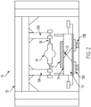
- Figure 2 illustrates an end view of an example of a device 110 for forming the composite structure 100, according to an example implementation.
- the device 110 includes an expandable pallet 112 having a forming surface 114 configured to receive thereon a laminated charge 116, and a plurality of rollers 118 oriented in a serial configuration for progressively urging the laminated charge 116 into a continuously expanding recess 120 defined by the expandable pallet 112 as the expandable pallet 112 is moved in a linear motion relative to a plurality of rollers 118.
- the plurality of rollers 118 shape the laminated charge 116 into at least part of a shape of the composite structure 100.
- FIG 2 an end view of the device is shown, and the plurality of rollers 118 are arranged in the serial configuration. As such, the view in Figure 2 only illustrates a first one of the plurality of rollers 118.
- the device 110 also includes a frame 122 with support structures 124a-b holding the plurality of rollers 118.
- the frame 122 is shown overhead of the expandable pallet 112, other configurations are possible as well, such as the frame 122 being mounted on sides of the expandable pallet 112.
- each roller of the plurality of rollers 118 is installed on a shaft 126 on which the roller rotates. Motion of the plurality of rollers 118 is driven by contact with the laminated charge 116.
- the plurality of rollers 118 may or may not be motorized or independently driven, but rather, spin passively due to contact with the laminated charge 116 as the laminated charge 116 moves in the linear motion underneath the plurality rollers 118.
- the plurality of rollers 118 react to the linear motion of the expandable pallet 112 moving the laminated charge 116 underneath the plurality of rollers 118.
- the device 110 includes rails 128a-b with bearing trucks driven by a motor connected to the device 110, and the expandable pallet 112 is positioned on top of the rails 128a-b.
- the expandable pallet 112 is moved in a linear motion underneath the plurality of rollers 118.
- Each successive roller of the plurality of rollers 118 is oriented progressively deeper than a preceding roller (based on height above the laminated charge 116), and the plurality of rollers 118 gradually press the laminated charge 116 into the recess 120 such that each successive roller of the plurality of rollers 118 presses the laminated charge 116 deeper into the recess 120. Movement of the expandable pallet 112 underneath the plurality of rollers 118 causes the plurality of rollers 118 to contact the laminated charge 116, for example.
- the plurality of rollers 118 gradually press the laminated charge 116 into the recess 120 due to each successive roller of the plurality of rollers 118 pressing the laminated charge deeper into the recess 120 as the expandable pallet 112 carrying the laminated charge 116 moves underneath the plurality of rollers 118.
- the gradually pressing includes each successive roller of the plurality of rollers 118 contributing to pressing the laminated charge 116 at least some amount deeper into the recess 120 as the expandable pallet 112 moves underneath the plurality of rollers 118. It is gradual in a sense that not one roller punches the laminated charge 116 fully into the recess 120, for example.
- Each roller of the plurality of rollers 118 defines a profile complementary to a desired shape of the composite structure 100.
- the composite structure 100 is a stringer.
- Figure 3 illustrates a side view of a portion of the device 110 for forming the composite structure 100, according to an example implementation.
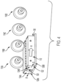
- Figure 4 illustrates a perspective view of the portion of the device 110 for forming the composite structure 100, according to an example implementation.
- Figures 3 and 4 illustrate the expandable pallet 112 and the plurality of rollers 118. In this example, there are four rollers 118a-d, however, more or fewer rollers may be included in the plurality of rollers 118.
- the plurality of rollers 118 are held stationary at respective heights (relational to heights above the laminated charge 116).
- a height above the laminated charge 116 for successive rollers decreases from roller 118a to roller 118b, and from roller 118b to roller 118c, and from roller 118c to roller 118d.
- the expandable pallet 112 moves in the linear motion underneath the plurality of rollers 118 so as to progressively expand from a first end 130 of the expandable pallet 112 to a second end 132 of the expandable pallet 112 opposite the first end 130.
- the expandable pallet 112 includes a pair of pallet members 134a-b, which are two separate blocks, that slide into and away from each other due to interlocking interior features.
- the recess 120 is a small area as shown in Figure 2 .
- the pair of pallet members 134a-b interlocked with one another define the recess 120 therebetween.
- the recess 120 grows larger.
- the pair of pallet members 134a-b are movable and translate relative to one another for modifying a size and configuration of the recess 120.
- the expandable pallet 112 moves in a linear motion due to the rails 128a-b in a direction shown by an arrow labeled "A" in Figures 3-4 to the right, and as the expandable pallet 112 moves, the laminated charge 116 (not shown in Figures 3-4 ) is progressively urged into the recess 120 that is continuously expanding by the plurality of rollers 118.
- the plurality of rollers 118 urge the laminated charge 116 into the recess 120 causing the expandable pallet 112 to expand in a direction substantially perpendicular to the linear motion.
- the expandable pallet 112 expands in a direction shown by arrows labeled "B".
- the plurality of rollers 118 urge the laminated charge 116 into the continuously expanding recess 120 causing the pair of pallet members 134a-b to move outward relative to one another and continuously expand the recess 120.
- the plurality of rollers 118 are oriented in a wedging configuration for progressively forming a shape of the composite structure 100, specifically a desired shape of a hat portion of the stringer.
- each roller of the plurality of rollers 118 is progressively deeper than a preceding roller such that the plurality of rollers 118 gradually press into the recess 120, urging the pair of pallet members 134a-b away from one another until the desired shape is created by the last roller 118d as the expandable pallet 112 passes thereunder.
- the plurality of rollers 118 define a profile, which is complementary to the desired shape of the hat portion of the stringer, for example.
- the expandable pallet 112 opens slowly by the pair of pallet members 134a-b sliding apart as the expandable pallet 112 moves in the linear motion underneath the plurality of rollers 118. For example, the expandable pallet 112 progressively opens from the first end 130 to the second end 132 as the expandable pallet 112 travels underneath the plurality of rollers 118.
- a force required to open the pair of pallet members 134a-b is adjustable with compressed air and air cylinders of the device 110, for example.
- the plurality of rollers 118 are arranged to move in a vertical direction (e.g., perpendicular to the linear motion of the expandable pallet 112).
- the vertical movement is controlled passively with a spring or air cylinder coupled to the plurality of rollers 118.
- the vertical movement is controlled actively by an electro motor. The vertical movement assist with and accommodates to changes in laminate thickness (e.g., ply drops).
- Figure 5 illustrates a perspective view of another example configuration of the plurality of rollers 118, according to an example implementation.
- the plurality of rollers 118A-D are arranged such that subsequent rollers have alternate shapes, such as progressively deeper roller shapes to further assist with each subsequent roller maintaining contact with the laminated charge 116, for example.
- Figure 5 conceptually illustrates arrangement of the plurality of rollers 118A-D in a serial configuration to demonstrate the progressively deeper shapes.
- Figure 6 illustrates a perspective view of a portion of an alternate configuration of the device 110 for forming the composite structure 100, according to an example implementation, which does not fall within the scope of the claims.
- the device 110 is shown with a single roller 118a.
- the laminated charge 116 includes a multi-ply fabric stringer that is formed by passing the expandable pallet 112 underneath the roller 118a multiples cycles, such as about ten to fifteen cycles. For each subsequent cycle, the roller 118a is lowered to simulate a multi-roller device with a desired pitch depth between rollers.
- alternate depths are used depending on the size and shape of the composite structure 100 being fabricated.
- a different shaped roller can be used too, other than a wedge shape as shown in Figure 6 , to create alternate shaped structures.
- a number of rollers used can vary as well.
- a different combination of rollers can be used, such as rollers with same diameters and varying heights above the expandable pallet 112 or rollers held at a same height above the expandable pallet 112 but with different or varying diameter or geometry.
- Examples of different configurations of the device 110 include the plurality of rollers 118 each about 1.27-2.54 mm (50-100 thousandths of an inch) deeper to create about a 25.4-50.8 mm (1-2 inch) tall stringer using twenty to thirty rollers, the and plurality of rollers 118 being flat with each roller slightly deeper than a previous roller to simulate a punch into the expandable pallet 112.
- Other example configurations of the device 110 using different combinations of number of the plurality of rollers 118, depth of the plurality of rollers 118, and shape of the plurality of rollers 118 are possible as well.
- Figures 7-9 illustrate an end perspective view of a portion of the device 110 in which a forming block 136 is used for forming the composite structure 100, according to an example implementation.
- the forming block 136 is applied over the laminated charge 116, and the forming block includes a base 138 and a protrusion 140 extending from the base 138 that defines a profile complementary to a desired shape of the composite structure 100.
- the expandable pallet 112 is then passed underneath the plurality of rollers 118 to progressively press the forming block 136 downward thereby continuously expanding the recess 120 and urging the laminated charge 116 into the recess 120.
- Figure 7 illustrates a first stage of the pressing in which the protrusion 140 of the forming block 136 enters the recess 120.
- Figure 8 illustrates a second stage, subsequent to pressing the forming block 136 by the plurality of rollers 118, in which the forming block 136 moves further downward and pushes the pair of pallet members 134a-b outward causing the recess 120 to enlarge.
- Figure 9 illustrates a third stage, subsequent to the second stage in which the forming block 136 is further pressed downward and pushes the pair of pallet members 134a-b further outward causing the recess 120 to enlarge.
- Figure 10 illustrates an end perspective view of a portion of the device 110 in which an alternate configuration of the forming block 136 is used for forming the composite structure 100, according to an example implementation.
- the forming block 136 is further defined as a flat plate 142 and a bladder 144 (e.g., stiffened bladder or a cureable tooling bladder), and the bladder 144 is progressively urged toward the expanding pallet 112 for forming the composite structure 100.
- the plurality of rollers 118 in this example may define a flat, cylindrical profile, and do not directly engage the laminated charge 116. Any shape can be used for the plurality of rollers 118 because the bladder 144 is pressed into the laminated charge 116 and creates the desired shape of the composite structure 100.
- the composite structure 100 is be crated off-line and then fed into a forming station for further processing. At this stage, the composite structure 100 is pre-formed and additional steps of bladder installation, noodle extrusion, compaction, and curing are performed. Thus, in some examples for fabrication, the composite structure 100 remains in distinct production areas while waiting to move to a next stage of production.
- a system is leveraged for high-rate stringer fabrication along a continuously moving manufacturing line to produce a number of composite structures continuously, such as about a few per minute.
- Each of the composite structures may include a desired length stringer package ready for curing.
- Figure 11 illustrates a side conceptual view of a system 150 for forming the composite structure 100, according to an example implementation.
- the system 150 includes an expandable pallet 112 having the forming surface 114 configured to receive thereon the laminated charge 116, the plurality of rollers 118 oriented in a serial configuration for progressively urging the laminated charge 116 into a continuously expanding recess 120 defined by the expandable pallet 112 and the plurality of rollers 118 shape the laminated charge 116 into at least part of a shape of the composite structure 100, and a feed assembly line 152 onto which the expandable pallet 112 with the laminated charge 116 is positioned and the feed assembly line 152 continuously moves the expandable pallet 112 in a linear motion relative to the plurality of rollers 118.
- the feed assembly line 152 includes a number of different stations for fabricating and then post-processing of the laminated charge 116 to create the composite structure 100. Each of the different stations resides over a portion of a conveyor belt 154 that moves the expandable pallet 112 in the linear motion relative to each station.
- a first station includes a laminator 156 that applies a full set of plies at once onto the expandable pallet 112.
- the full set of plies is the laminated charge 116.
- the conveyor belt 154 moves the expandable pallet 112 in a linear motion (as shown in Figure 10 by the arrows to the right), driven by a motor, and progresses the expandable pallet 112 now with the laminated charge 116 positioned thereon to the next station that includes the plurality of rollers 118. As described, the plurality of rollers 118 progressively urge the laminated charge 116 into the recess 120 of the expandable pallet 112.
- the conveyor belt 154 continues to move the expandable pallet 112 in a linear motion (as shown in Figure 11 by the arrows to the right) and progresses the expandable pallet 112 now with the laminated charge 116 urged into the recess 120 to the next station that includes a bladder station 158.
- the bladder station 158 is positioned after the plurality of rollers 118 within the feed assembly line 152, and as the expandable pallet 112 moves past the bladder station 158, the bladder 144 is applied onto the laminated charge 116 into a cavity 160 formed by the plurality of rollers 118.
- Figures 12A-12C illustrate an example sequence of installation of the bladder 144 in the bladder station 158, according to an example implementation.
- the bladder 144 is laid within the cavity 160 in a lengthwise manner starting on a right side that exits the plurality of rollers 118.
- the bladder 144 is further inserted into the cavity 160.
- the bladder 144 is manually inserted into the cavity 160.
- machinery (not shown) is used to insert the bladder 144 into the cavity 160.
- Figure 12B illustrates the bladder 144 further inserted into the cavity 160 as the expandable pallet 112 continues to move through the bladder station 158.
- Figure 12C illustrates the bladder 144 fully installed into the cavity 160 at an end of the bladder station 158.
- the expandable pallet 112 is continuously moved through the feed assembly line 152 and a portion of the expandable pallet 112 may be underneath the plurality of rollers 118 while another portion of the expandable pallet 112 has entered the bladder station 158.
- the conveyor belt 154 continues to move the expandable pallet 112 in a linear motion (as shown in Figure 11 by the arrows to the right) and progresses the expandable pallet 112 now with the bladder 144 installed to the next station that includes a radius filler station 161 that is positioned after the bladder station 158 within the feed assembly line 152. As the expandable pallet 112 moves past the radius filler station 161, a radius filler 162 is installed into the laminated charge 116.
- Gaps or void regions can be formed by a radius of any curved pieces of the laminated charge. Such gaps or void regions are typically referred to as “radius filler regions" or “noodle regions”.
- the radius filler station fills the radius filler regions or noodle regions with radius filler elements or "noodles" made of composite material or adhesive/epoxy material and having a generally triangular cross-section to provide additional structural reinforcement to such regions.
- the radius filler 162 includes carbon fiber-reinforced plastic (CFRP) that is placed by machinery into the gaps or voids as the expandable pallet 112 moves through the radius filler station 161.
- CFRP carbon fiber-reinforced plastic
- the conveyor belt 154 continues to move the expandable pallet 112 in a linear motion (as shown in Figure 11 by the arrows to the right) and progresses the expandable pallet 112 now with the radius filler 162 installed to the next station that includes a compaction station 164 that is positioned after the radius filler station 161 within the feed assembly line 152. As the expandable pallet 112 moves through the compaction station 164, the laminated charge 116 is compacted into a completed package.
- the system 150 operates the feed assembly line 152 by continuously moving the expandable pallet 112 in the linear motion enabling fabrication of composite structures at a rate of about multiple feet per minute.
- the continuously moving assembly line enables a substantial increase in a rate of production and manufacturing efficiency of composite stiffeners because there is no stopping for alternate tooling to be placed.
- the bladder station 158 is re-ordered to be positioned in the feed assembly line 152 before the plurality of rollers 118.
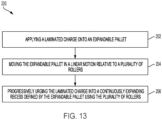
- Figure 13 is a flowchart illustrating an example of a method 200 of forming a composite structure, according to an example implementation.
- Method 200 shown in Figure 13 presents an example of a method that could be used with the device 110 shown throughout the Figures or with the system 150 shown in Figure 10 , for example.
- devices or systems may be used or configured to perform logical functions presented in Figure 13 .
- components of the devices and/or systems may be configured to perform the functions such that the components are actually configured and structured (with hardware and/or software) to enable such performance.
- components of the devices and/or systems may be arranged to be adapted to, capable of, or suited for performing the functions, such as when operated in a specific manner.
- Method 200 may include one or more operations, functions, or actions as illustrated by one or more of blocks 202-206. Although the blocks are illustrated in a sequential order, these blocks may also be performed in parallel, and/or in a different order than those described herein. Also, the various blocks may be combined into fewer blocks, divided into additional blocks, and/or removed based upon the desired implementation.
- one or more blocks of the method 200 may be represented in program code or circuitry used for controlling robotic mechanisms for performing functions related to forming the composite structure. While at least some portions of the method 200 and variations thereof may be executed automatically using, for example, one or more robotic armatures controlled by program code operating in accordance with the method 200, some tasks may also or alternatively be performed manually. Thus, within examples, certain functionality described with respect to the method 200 may be performed automatically while other portions can be performed manually. Alternatively, all blocks of the method 200 may be performed automatically or all blocks of the method 200 may be performed manually.
- such functionality includes one or more instructions executable by a processor for implementing specific logical functions or steps in the process that are carried out by machinery or devices.
- the program code may be stored on any type of computer readable medium or data storage, for example, such as a storage device including a disk or hard drive. Further, the program code can be encoded on a computer-readable storage media in a machine-readable format, or on other non-transitory media or articles of manufacture.
- the computer readable medium may include non-transitory computer readable medium or memory, for example, such as computer-readable media that stores data for short periods of time like register memory, processor cache and Random Access Memory (RAM).
- the computer readable medium may also include non-transitory media, such as secondary or persistent long term storage, like read only memory (ROM), optical or magnetic disks, compact-disc read only memory (CD-ROM), for example.
- the computer readable media may also be any other volatile or non-volatile storage systems.
- the computer readable medium may be considered a tangible computer readable storage medium, for example.
- blocks or portions of blocks in Figure 13 may represent circuitry that is wired to perform the specific logical functions in the process.
- Alternative implementations are included within the scope of the examples of the present disclosure in which functions may be executed out of order from that shown or discussed, including substantially concurrent or in reverse order, depending on the functionality involved, as would be understood by those reasonably skilled in the art.
- the method 200 includes applying the laminated charge 116 onto the expandable pallet 112.
- the method 200 includes moving the expandable pallet 112 in a linear motion relative to the plurality of rollers 118.
- a roller of the plurality of rollers 118 defines a profile complementary to a desired shape of the composite structure 100.
- the composite structure 100 is a stringer.
- the method 200 includes progressively urging the laminated charge 116 into a continuously expanding recess 120 defined by the expandable pallet 112 using the plurality of rollers 118, and the plurality of rollers 118 are oriented in a serial configuration so as to shape the laminated charge 116 into at least part of a shape of the composite structure 100.
- each successive roller of the plurality of rollers 118 is oriented progressively deeper than a preceding roller, and progressively urging the laminated charge 116 into the continuously expanding recess 120 defined by the expandable pallet using the plurality of rollers 118 includes gradually pressing the laminated charge 116 into the recess 120 by the plurality of rollers 118 and each successive roller of the plurality of rollers 118 presses the laminated charge 116 deeper into the recess 120.
- moving the expandable pallet 112 in the linear motion relative to the plurality of rollers 118 and progressively urging the laminated charge 116 into the continuously expanding recess 120 defined by the expandable pallet 112 using the plurality of rollers 118 includes progressively expanding the expandable pallet 112 from a first end 130 to a second end 132 opposite the first end 130.
- the expandable pallet 112 includes a pair of pallet members 134a-b interlocked with one another defining the recess 120 therebetween, and progressively urging the laminated charge 116 into the continuously expanding recess 120 defined by the expandable pallet 112 includes the plurality of rollers 118 urging the laminated charge 116 into the continuously expanding recess 120 causing the pair of pallet members 134a-b to move outward relative to one another and continuously expand the recess 120.
- the plurality of rollers 118 are held stationary at respective heights, and the method 200 further includes moving the expandable pallet 112 in the linear motion underneath the plurality of rollers 118. Additional functions of the method 200 also may include the plurality of rollers 118 urging the laminated charge 116 into the continuously expanding recess 120 causing the expandable pallet 112 to expand in a direction substantially perpendicular to the linear motion.
- the method 200 optionally includes after progressively urging the laminated charge 116 into the continuously expanding recess 120 defined by the expandable pallet 112 using the plurality of rollers 118, applying a bladder 144 onto the laminated charge 116 into a cavity 160 formed by the plurality of rollers 118.
- the method 200 may optionally include after applying the bladder 144 onto the laminated charge 116, installing radius filler 162 into the laminated charge 116.
- the method 200 may optionally after installing the radius filler 162 into the laminated charge 116, compacting the laminated charge 116.
- applying the laminated charge 116 onto the expandable pallet 112, progressively urging the laminated charge 116 into the continuously expanding recess 120 defined by the expandable pallet 112 using the plurality of rollers 118, applying the bladder 144 onto the laminated charge 116, installing the radius filler 162 into the laminated charge 116, and compacting the laminated charge 116 are performed along a feed assembly line 152 by continuously moving the expandable pallet 112 in the linear motion.
- the method 200 optionally includes after applying the laminated charge 116 onto the expandable pallet 112, applying a forming block 136 over the laminated charge 116, and the forming block 136 comprises a base 138 and a protrusion 140 extending from the base 138 that defines a profile complementary to a desired shape of the composite structure 100.
- progressively urging the laminated charge 116 into the continuously expanding recess 120 defined by the expandable pallet 112 using the plurality of rollers 118 includes progressively pressing the forming block 136 downward thereby continuously expanding the recess 120 and urging the laminated charge 116 into the recess 120.
- Example devices, systems, and methods described herein support fabrication of composite structures along a continuously moving manufacturing line, which significantly enhances efficiency, reduces time to form the composite structures, and reduces space required for fabrication. Altogether, a cost reduction in composite structure fabrication is also achievable with the example devices, systems, and methods described herein.
Landscapes
- Engineering & Computer Science (AREA)
- Mechanical Engineering (AREA)
- Chemical & Material Sciences (AREA)
- Composite Materials (AREA)
- Moulding By Coating Moulds (AREA)
Claims (15)
- Verfahren (200) zum Bilden einer Verbundwerkstoffstruktur (100), wobei das Verfahren aufweist:Aufbringen (202) einer laminierten Ladung (116) auf eine ausdehnbare Palette;Bewegen (204) der ausdehnbaren Palette (112) in einer linearen Bewegung relativ zu einer Vielzahl von Walzen (112); undfortschreitendes Eindrücken (206) der laminierten Ladung (116) in eine sich kontinuierlich ausdehnende Ausnehmung (120), die durch die ausdehnbare Palette (112) definiert ist, unter Verwendung der Vielzahl von Walzen (118), wobei die Vielzahl von Walzen (118) in einer seriellen Konfiguration ausgerichtet sind, um die laminierte Ladung (116) in zumindest einen Teil einer Form der Verbundwerkstoffstruktur (100) zu formen.
- Verfahren nach Anspruch 1, wobei eine Walze der Vielzahl von Walzen (118) ein Profil definiert, das komplementär zu einer gewünschten Form der Verbundwerkstoffstruktur (100) ist.
- Verfahren nach Anspruch 1 oder 2, wobei jede aufeinanderfolgende Walze der Vielzahl von Walzen (118) progressiv tiefer ausgerichtet ist als eine vorhergehende Walze, und
wobei das fortschreitende Eindrücken der laminierten Ladung (116) in die sich kontinuierlich ausdehnende Ausnehmung (120), die durch die ausdehnbare Palette (112) definiert ist, unter Verwendung der Vielzahl von Walzen (112) aufweist:
allmähliches Drücken der laminierten Ladung (116) in die Ausnehmung (120) durch die Vielzahl von Walzen (118), wobei jede aufeinanderfolgende Walze der Vielzahl von Walzen (118) die laminierte Ladung (116) tiefer in die Ausnehmung (120) drückt. - Verfahren nach Anspruch 1 oder 2, wobei die Vielzahl von Walzen (118) in den jeweiligen Höhen stationär gehalten werden und das Verfahren des Weiteren aufweist:
Bewegen der ausdehnbaren Palette (112) in der linearen Bewegung unterhalb der Vielzahl von Walzen (118). - Verfahren nach Anspruch 4, des Weiteren aufweisend:
die Vielzahl von Walzen (118) die laminierte Ladung (116) in die sich kontinuierlich ausdehnende Ausnehmung (120) drückt, wodurch sich die ausdehnbare Palette (112) in einer Richtung ausdehnt, die im Wesentlichen senkrecht zu der linearen Bewegung steht. - Verfahren nach einem der Ansprüche 1-5, wobei das Bewegen der ausdehnbaren Palette (112) in der linearen Bewegung relativ zu der Vielzahl von Walzen (118) und das fortschreitende Eindrücken der laminierten Ladung (116) in die sich kontinuierlich ausdehnende Ausnehmung (120), die durch die ausdehnbare Palette (112) definiert ist, unter Verwendung der Vielzahl von Walzen (118) des Weiteren aufweist:
fortschreitendes Ausdehnen der ausdehnbaren Palette (112) von einem ersten Ende (130) zu einem zweiten Ende (132) gegenüber dem ersten Ende. - Verfahren nach einem der Ansprüche 1-6, wobei die ausdehnbare Palette (112) ein Paar von Palettenelementen (134a-b) aufweist, die miteinander verriegelt sind und die Ausnehmung (120) dazwischen definieren, und wobei das fortschreitende Drängen der laminierten Ladung (116) in die sich kontinuierlich ausdehnende Ausnehmung (120), die durch die ausdehnbare Palette (112) definiert ist, aufweist:
die Vielzahl von Walzen (118), die die laminierte Ladung (116) in die sich kontinuierlich ausdehnende Ausnehmung (120) drängen, was das Paar von Palettenelementen veranlasst, sich relativ zueinander nach außen zu bewegen und die Ausnehmung (120) kontinuierlich auszudehnen. - Verfahren nach einem der Ansprüche 1-7, des Weiteren aufweisend:nachdem die laminierte Ladung (116) unter Verwendung der Vielzahl von Walzen (118) schrittweise in die durch die ausdehnbare Palette (112) definierte, sich kontinuierlich ausdehnende Ausnehmung (120) gedrückt wurde,Aufbringen einer Blase (144) auf die laminierte Ladung (116) in einen durch die Vielzahl von Walzen (118) gebildeten Hohlraum.
- Verfahren nach Anspruch 8, des Weiteren aufweisend:
nach dem Aufbringen der Blase auf die laminierte Ladung (116), Einbringen eines Radiusfüllers (162) in die laminierte Ladung (116). - Verfahren nach Anspruch 9, des Weiteren aufweisend:
nach dem Einbringen des Radiusfüllers in die laminierte Ladung (116), Verdichten der laminierten Ladung (116) und wobei das Aufbringen der laminierten Ladung (116) auf die ausdehnbare Palette (112) das fortschreitende Eindrücken der laminierten Ladung (116) in die sich kontinuierlich ausdehnende Ausnehmung (120), die durch die ausdehnbare Palette (112) definiert ist, unter Verwendung der Vielzahl von Walzen (118), das Aufbringen der Blase auf die laminierte Ladung (116), das Einbringen des Radiusfüllers in die laminierte Ladung (116) und das Verdichten der laminierten Ladung (116) entlang einer Zuführungsbaulinie (152) durch kontinuierliches Bewegen der ausdehnbaren Palette (112) in der linearen Bewegung ausgeführt werden. - Verfahren nach einem der Ansprüche 1-10, des Weiteren aufweisend:
nach dem Aufbringen der laminierten Ladung (116) auf die ausdehnbare Palette (112), Aufbringen eines Formblocks (136) über die laminierte Ladung (116), wobei der Formblock eine Basis (138) und einen Vorsprung (140) aufweist, der sich von der Basis aus erstreckt und ein Profil definiert, das zu einer gewünschten Form der Verbundwerkstoff-Struktur (100) komplementär ist. - Verfahren nach Anspruch 11, wobei die laminierte Charge (116) nach und nach in die
Ladung (116) in die sich kontinuierlich ausdehnende Ausnehmung (120), die durch die ausdehnbare Palette (112) definiert ist, unter Verwendung der Vielzahl von Walzen (118) aufweist:
fortschreitendes Drücken des Formblocks nach unten, wodurch die Ausnehmung (120) kontinuierlich ausgeweitet wird und die laminierte Ladung (116) in die Ausnehmung (120) gedrückt wird. - System (150) zum Ausbilden einer Verbundwerkstoffstruktur (100), wobei das System aufweist:eine ausdehnbare Palette (112) mit einer Formoberfläche zum Aufnehmen einer laminierten Ladung (116) darauf;eine Vielzahl von Walzen (118), die in einer seriellen Konfiguration ausgebildet sind, um die laminierte Ladung (116) fortschreitend in eine sich kontinuierlich ausdehnende Ausnehmung (120) zu drängen, die durch die ausdehnbare Palette (112) definiert ist, wobei die Vielzahl von Walzen (118) die laminierte Ladung (116) zumindest teilweise in eine Form der Verbundwerkstoffstruktur (100) formt; undeine Zuführungsmontagelinie (152), auf der die ausdehnbare Palette (112) mit der laminierte Ladung (116) positioniert wird, wobei die Zuführungsmontagelinie kontinuierlich die ausdehnbare Palette (112) in einer linearen Bewegung relativ zu der Vielzahl von Walzen (118) bewegt.
- System nach Anspruch 13, des Weiteren aufweisend:
eine Blasenstation (158), die nach der Vielzahl von Walzen (118) innerhalb der Zuführungsmontagelinie positioniert ist, wobei eine Blase (144) auf die laminierte Ladung (116) in einen durch die Vielzahl von Walzen (118) gebildeten Hohlraum aufgebracht wird, während sich die ausdehnbare Palette (112) an der Blasenstation vorbeibewegt. - System nach Anspruch 14, des Weiteren aufweisend:
eine Radiusfüllerstation (161), die nach der Blasenstation innerhalb der Zuführungsmontagelinie angeordnet ist, wobei, während sich die ausdehnbare Palette (112) an der Radiusfüllerstation vorbeibewegt, ein Radiusfüller in die laminierte Ladung (116) installiert wird.
Applications Claiming Priority (1)
| Application Number | Priority Date | Filing Date | Title |
|---|---|---|---|
| US202163196361P | 2021-06-03 | 2021-06-03 |
Publications (2)
| Publication Number | Publication Date |
|---|---|
| EP4098430A1 EP4098430A1 (de) | 2022-12-07 |
| EP4098430B1 true EP4098430B1 (de) | 2024-01-31 |
Family
ID=81585549
Family Applications (1)
| Application Number | Title | Priority Date | Filing Date |
|---|---|---|---|
| EP22170030.5A Active EP4098430B1 (de) | 2021-06-03 | 2022-04-26 | Verfahren, vorrichtungen und systeme zur herstellung einer verbundstruktur unter verwendung einer expandierbaren palette |
Country Status (4)
| Country | Link |
|---|---|
| US (2) | US12049050B2 (de) |
| EP (1) | EP4098430B1 (de) |
| JP (1) | JP2022186641A (de) |
| CN (1) | CN115431539A (de) |
Families Citing this family (2)
| Publication number | Priority date | Publication date | Assignee | Title |
|---|---|---|---|---|
| US11787133B2 (en) * | 2022-01-25 | 2023-10-17 | The Boeing Company | Conveyor forming composite stringers |
| US20250242552A1 (en) * | 2024-01-26 | 2025-07-31 | The Boeing Company | Expandable pallet for forming a composite structure |
Family Cites Families (5)
| Publication number | Priority date | Publication date | Assignee | Title |
|---|---|---|---|---|
| US7249943B2 (en) | 2003-08-01 | 2007-07-31 | Alliant Techsystems Inc. | Apparatus for forming composite stiffeners and reinforcing structures |
| US7527759B2 (en) * | 2005-04-13 | 2009-05-05 | The Boeing Company | Method and apparatus for forming structural members |
| US8052823B2 (en) * | 2008-01-31 | 2011-11-08 | Alliant Techsystems Inc. | Stiffener tool positioning apparatus |
| EP2915659B1 (de) * | 2014-03-06 | 2020-04-29 | Airbus Defence and Space GmbH | Faserverbundbauteil mit strahlvernetztem Füllkörper |
| US10710318B2 (en) * | 2017-05-26 | 2020-07-14 | The Boeing Company | High speed composite layup via multiple machines |
-
2022
- 2022-03-17 US US17/697,004 patent/US12049050B2/en active Active
- 2022-04-15 CN CN202210393373.4A patent/CN115431539A/zh active Pending
- 2022-04-26 EP EP22170030.5A patent/EP4098430B1/de active Active
- 2022-05-31 JP JP2022088261A patent/JP2022186641A/ja active Pending
-
2024
- 2024-06-27 US US18/757,235 patent/US12311618B2/en active Active
Also Published As
| Publication number | Publication date |
|---|---|
| US12311618B2 (en) | 2025-05-27 |
| CN115431539A (zh) | 2022-12-06 |
| US12049050B2 (en) | 2024-07-30 |
| US20240343002A1 (en) | 2024-10-17 |
| US20220388256A1 (en) | 2022-12-08 |
| JP2022186641A (ja) | 2022-12-15 |
| EP4098430A1 (de) | 2022-12-07 |
Similar Documents
| Publication | Publication Date | Title |
|---|---|---|
| US12311618B2 (en) | Methods, devices, and systems for forming a composite structure using an expandable pallet | |
| CN111452947B (zh) | 成形复合桁条 | |
| EP3970939B1 (de) | Zwangsformen von konturierten zusammengesetzten hutspanten | |
| EP2906412B1 (de) | Verfahren und vorrichtung zur herstellung von faserverbundteilen | |
| US10414107B2 (en) | Method and material efficient tooling for continuous compression molding | |
| CN106335178B (zh) | 形成成一轮廓的帽形复合加强件的方法和装置 | |
| CN102950693A (zh) | 用于制造可变尺度、成形的复合加强件的方法和设备 | |
| EP4241972B1 (de) | Stringerformungsvorrichtung und -verfahren | |
| CN111136936B (zh) | 一种多角度铺层设计帽形长桁预浸料拉挤成型装置 | |
| US12194695B2 (en) | Conveyor forming composite stringers | |
| CN112477191A (zh) | 一种用于复合材料帽型长桁铺放的装置 | |
| CN120481332A (zh) | 一种机器人式复合材料长桁连续自动辊压装置及方法 | |
| CN112008960A (zh) | 用于形成t形轮廓复合件的复合成型工位和方法及复合件 | |
| HK1139105B (en) | Method and material efficient tooling for continuous compression molding |
Legal Events
| Date | Code | Title | Description |
|---|---|---|---|
| PUAI | Public reference made under article 153(3) epc to a published international application that has entered the european phase |
Free format text: ORIGINAL CODE: 0009012 |
|
| STAA | Information on the status of an ep patent application or granted ep patent |
Free format text: STATUS: THE APPLICATION HAS BEEN PUBLISHED |
|
| AK | Designated contracting states |
Kind code of ref document: A1 Designated state(s): AL AT BE BG CH CY CZ DE DK EE ES FI FR GB GR HR HU IE IS IT LI LT LU LV MC MK MT NL NO PL PT RO RS SE SI SK SM TR |
|
| RAP3 | Party data changed (applicant data changed or rights of an application transferred) |
Owner name: THE BOEING COMPANY |
|
| STAA | Information on the status of an ep patent application or granted ep patent |
Free format text: STATUS: REQUEST FOR EXAMINATION WAS MADE |
|
| 17P | Request for examination filed |
Effective date: 20230523 |
|
| RBV | Designated contracting states (corrected) |
Designated state(s): AL AT BE BG CH CY CZ DE DK EE ES FI FR GB GR HR HU IE IS IT LI LT LU LV MC MK MT NL NO PL PT RO RS SE SI SK SM TR |
|
| GRAP | Despatch of communication of intention to grant a patent |
Free format text: ORIGINAL CODE: EPIDOSNIGR1 |
|
| STAA | Information on the status of an ep patent application or granted ep patent |
Free format text: STATUS: GRANT OF PATENT IS INTENDED |
|
| INTG | Intention to grant announced |
Effective date: 20231020 |
|
| GRAS | Grant fee paid |
Free format text: ORIGINAL CODE: EPIDOSNIGR3 |
|
| GRAA | (expected) grant |
Free format text: ORIGINAL CODE: 0009210 |
|
| STAA | Information on the status of an ep patent application or granted ep patent |
Free format text: STATUS: THE PATENT HAS BEEN GRANTED |
|
| P01 | Opt-out of the competence of the unified patent court (upc) registered |
Effective date: 20231129 |
|
| AK | Designated contracting states |
Kind code of ref document: B1 Designated state(s): AL AT BE BG CH CY CZ DE DK EE ES FI FR GB GR HR HU IE IS IT LI LT LU LV MC MK MT NL NO PL PT RO RS SE SI SK SM TR |
|
| REG | Reference to a national code |
Ref country code: GB Ref legal event code: FG4D Ref country code: CH Ref legal event code: EP |
|
| REG | Reference to a national code |
Ref country code: DE Ref legal event code: R096 Ref document number: 602022001742 Country of ref document: DE |
|
| REG | Reference to a national code |
Ref country code: IE Ref legal event code: FG4D |
|
| REG | Reference to a national code |
Ref country code: LT Ref legal event code: MG9D |
|
| REG | Reference to a national code |
Ref country code: NL Ref legal event code: MP Effective date: 20240131 |
|
| PG25 | Lapsed in a contracting state [announced via postgrant information from national office to epo] |
Ref country code: IS Free format text: LAPSE BECAUSE OF FAILURE TO SUBMIT A TRANSLATION OF THE DESCRIPTION OR TO PAY THE FEE WITHIN THE PRESCRIBED TIME-LIMIT Effective date: 20240531 |
|
| PG25 | Lapsed in a contracting state [announced via postgrant information from national office to epo] |
Ref country code: LT Free format text: LAPSE BECAUSE OF FAILURE TO SUBMIT A TRANSLATION OF THE DESCRIPTION OR TO PAY THE FEE WITHIN THE PRESCRIBED TIME-LIMIT Effective date: 20240131 |
|
| PG25 | Lapsed in a contracting state [announced via postgrant information from national office to epo] |
Ref country code: GR Free format text: LAPSE BECAUSE OF FAILURE TO SUBMIT A TRANSLATION OF THE DESCRIPTION OR TO PAY THE FEE WITHIN THE PRESCRIBED TIME-LIMIT Effective date: 20240501 |
|
| REG | Reference to a national code |
Ref country code: AT Ref legal event code: MK05 Ref document number: 1653597 Country of ref document: AT Kind code of ref document: T Effective date: 20240131 |
|
| PG25 | Lapsed in a contracting state [announced via postgrant information from national office to epo] |
Ref country code: RS Free format text: LAPSE BECAUSE OF FAILURE TO SUBMIT A TRANSLATION OF THE DESCRIPTION OR TO PAY THE FEE WITHIN THE PRESCRIBED TIME-LIMIT Effective date: 20240430 Ref country code: HR Free format text: LAPSE BECAUSE OF FAILURE TO SUBMIT A TRANSLATION OF THE DESCRIPTION OR TO PAY THE FEE WITHIN THE PRESCRIBED TIME-LIMIT Effective date: 20240131 Ref country code: NL Free format text: LAPSE BECAUSE OF FAILURE TO SUBMIT A TRANSLATION OF THE DESCRIPTION OR TO PAY THE FEE WITHIN THE PRESCRIBED TIME-LIMIT Effective date: 20240131 |
|
| PG25 | Lapsed in a contracting state [announced via postgrant information from national office to epo] |
Ref country code: ES Free format text: LAPSE BECAUSE OF FAILURE TO SUBMIT A TRANSLATION OF THE DESCRIPTION OR TO PAY THE FEE WITHIN THE PRESCRIBED TIME-LIMIT Effective date: 20240131 |
|
| PG25 | Lapsed in a contracting state [announced via postgrant information from national office to epo] |
Ref country code: AT Free format text: LAPSE BECAUSE OF FAILURE TO SUBMIT A TRANSLATION OF THE DESCRIPTION OR TO PAY THE FEE WITHIN THE PRESCRIBED TIME-LIMIT Effective date: 20240131 |
|
| PG25 | Lapsed in a contracting state [announced via postgrant information from national office to epo] |
Ref country code: RS Free format text: LAPSE BECAUSE OF FAILURE TO SUBMIT A TRANSLATION OF THE DESCRIPTION OR TO PAY THE FEE WITHIN THE PRESCRIBED TIME-LIMIT Effective date: 20240430 Ref country code: NO Free format text: LAPSE BECAUSE OF FAILURE TO SUBMIT A TRANSLATION OF THE DESCRIPTION OR TO PAY THE FEE WITHIN THE PRESCRIBED TIME-LIMIT Effective date: 20240430 Ref country code: NL Free format text: LAPSE BECAUSE OF FAILURE TO SUBMIT A TRANSLATION OF THE DESCRIPTION OR TO PAY THE FEE WITHIN THE PRESCRIBED TIME-LIMIT Effective date: 20240131 Ref country code: LT Free format text: LAPSE BECAUSE OF FAILURE TO SUBMIT A TRANSLATION OF THE DESCRIPTION OR TO PAY THE FEE WITHIN THE PRESCRIBED TIME-LIMIT Effective date: 20240131 Ref country code: IS Free format text: LAPSE BECAUSE OF FAILURE TO SUBMIT A TRANSLATION OF THE DESCRIPTION OR TO PAY THE FEE WITHIN THE PRESCRIBED TIME-LIMIT Effective date: 20240531 Ref country code: HR Free format text: LAPSE BECAUSE OF FAILURE TO SUBMIT A TRANSLATION OF THE DESCRIPTION OR TO PAY THE FEE WITHIN THE PRESCRIBED TIME-LIMIT Effective date: 20240131 Ref country code: GR Free format text: LAPSE BECAUSE OF FAILURE TO SUBMIT A TRANSLATION OF THE DESCRIPTION OR TO PAY THE FEE WITHIN THE PRESCRIBED TIME-LIMIT Effective date: 20240501 Ref country code: FI Free format text: LAPSE BECAUSE OF FAILURE TO SUBMIT A TRANSLATION OF THE DESCRIPTION OR TO PAY THE FEE WITHIN THE PRESCRIBED TIME-LIMIT Effective date: 20240131 Ref country code: ES Free format text: LAPSE BECAUSE OF FAILURE TO SUBMIT A TRANSLATION OF THE DESCRIPTION OR TO PAY THE FEE WITHIN THE PRESCRIBED TIME-LIMIT Effective date: 20240131 Ref country code: BG Free format text: LAPSE BECAUSE OF FAILURE TO SUBMIT A TRANSLATION OF THE DESCRIPTION OR TO PAY THE FEE WITHIN THE PRESCRIBED TIME-LIMIT Effective date: 20240131 Ref country code: AT Free format text: LAPSE BECAUSE OF FAILURE TO SUBMIT A TRANSLATION OF THE DESCRIPTION OR TO PAY THE FEE WITHIN THE PRESCRIBED TIME-LIMIT Effective date: 20240131 |
|
| PG25 | Lapsed in a contracting state [announced via postgrant information from national office to epo] |
Ref country code: PL Free format text: LAPSE BECAUSE OF FAILURE TO SUBMIT A TRANSLATION OF THE DESCRIPTION OR TO PAY THE FEE WITHIN THE PRESCRIBED TIME-LIMIT Effective date: 20240131 Ref country code: PT Free format text: LAPSE BECAUSE OF FAILURE TO SUBMIT A TRANSLATION OF THE DESCRIPTION OR TO PAY THE FEE WITHIN THE PRESCRIBED TIME-LIMIT Effective date: 20240531 |
|
| PG25 | Lapsed in a contracting state [announced via postgrant information from national office to epo] |
Ref country code: SE Free format text: LAPSE BECAUSE OF FAILURE TO SUBMIT A TRANSLATION OF THE DESCRIPTION OR TO PAY THE FEE WITHIN THE PRESCRIBED TIME-LIMIT Effective date: 20240131 Ref country code: PT Free format text: LAPSE BECAUSE OF FAILURE TO SUBMIT A TRANSLATION OF THE DESCRIPTION OR TO PAY THE FEE WITHIN THE PRESCRIBED TIME-LIMIT Effective date: 20240531 Ref country code: PL Free format text: LAPSE BECAUSE OF FAILURE TO SUBMIT A TRANSLATION OF THE DESCRIPTION OR TO PAY THE FEE WITHIN THE PRESCRIBED TIME-LIMIT Effective date: 20240131 Ref country code: LV Free format text: LAPSE BECAUSE OF FAILURE TO SUBMIT A TRANSLATION OF THE DESCRIPTION OR TO PAY THE FEE WITHIN THE PRESCRIBED TIME-LIMIT Effective date: 20240131 |
|
| PG25 | Lapsed in a contracting state [announced via postgrant information from national office to epo] |
Ref country code: DK Free format text: LAPSE BECAUSE OF FAILURE TO SUBMIT A TRANSLATION OF THE DESCRIPTION OR TO PAY THE FEE WITHIN THE PRESCRIBED TIME-LIMIT Effective date: 20240131 |
|
| PG25 | Lapsed in a contracting state [announced via postgrant information from national office to epo] |
Ref country code: SM Free format text: LAPSE BECAUSE OF FAILURE TO SUBMIT A TRANSLATION OF THE DESCRIPTION OR TO PAY THE FEE WITHIN THE PRESCRIBED TIME-LIMIT Effective date: 20240131 |
|
| PG25 | Lapsed in a contracting state [announced via postgrant information from national office to epo] |
Ref country code: EE Free format text: LAPSE BECAUSE OF FAILURE TO SUBMIT A TRANSLATION OF THE DESCRIPTION OR TO PAY THE FEE WITHIN THE PRESCRIBED TIME-LIMIT Effective date: 20240131 Ref country code: CZ Free format text: LAPSE BECAUSE OF FAILURE TO SUBMIT A TRANSLATION OF THE DESCRIPTION OR TO PAY THE FEE WITHIN THE PRESCRIBED TIME-LIMIT Effective date: 20240131 |
|
| PG25 | Lapsed in a contracting state [announced via postgrant information from national office to epo] |
Ref country code: SK Free format text: LAPSE BECAUSE OF FAILURE TO SUBMIT A TRANSLATION OF THE DESCRIPTION OR TO PAY THE FEE WITHIN THE PRESCRIBED TIME-LIMIT Effective date: 20240131 |
|
| PG25 | Lapsed in a contracting state [announced via postgrant information from national office to epo] |
Ref country code: SM Free format text: LAPSE BECAUSE OF FAILURE TO SUBMIT A TRANSLATION OF THE DESCRIPTION OR TO PAY THE FEE WITHIN THE PRESCRIBED TIME-LIMIT Effective date: 20240131 Ref country code: SK Free format text: LAPSE BECAUSE OF FAILURE TO SUBMIT A TRANSLATION OF THE DESCRIPTION OR TO PAY THE FEE WITHIN THE PRESCRIBED TIME-LIMIT Effective date: 20240131 Ref country code: RO Free format text: LAPSE BECAUSE OF FAILURE TO SUBMIT A TRANSLATION OF THE DESCRIPTION OR TO PAY THE FEE WITHIN THE PRESCRIBED TIME-LIMIT Effective date: 20240131 Ref country code: EE Free format text: LAPSE BECAUSE OF FAILURE TO SUBMIT A TRANSLATION OF THE DESCRIPTION OR TO PAY THE FEE WITHIN THE PRESCRIBED TIME-LIMIT Effective date: 20240131 Ref country code: DK Free format text: LAPSE BECAUSE OF FAILURE TO SUBMIT A TRANSLATION OF THE DESCRIPTION OR TO PAY THE FEE WITHIN THE PRESCRIBED TIME-LIMIT Effective date: 20240131 Ref country code: CZ Free format text: LAPSE BECAUSE OF FAILURE TO SUBMIT A TRANSLATION OF THE DESCRIPTION OR TO PAY THE FEE WITHIN THE PRESCRIBED TIME-LIMIT Effective date: 20240131 |
|
| REG | Reference to a national code |
Ref country code: DE Ref legal event code: R097 Ref document number: 602022001742 Country of ref document: DE |
|
| PG25 | Lapsed in a contracting state [announced via postgrant information from national office to epo] |
Ref country code: MC Free format text: LAPSE BECAUSE OF FAILURE TO SUBMIT A TRANSLATION OF THE DESCRIPTION OR TO PAY THE FEE WITHIN THE PRESCRIBED TIME-LIMIT Effective date: 20240131 |
|
| PG25 | Lapsed in a contracting state [announced via postgrant information from national office to epo] |
Ref country code: MC Free format text: LAPSE BECAUSE OF FAILURE TO SUBMIT A TRANSLATION OF THE DESCRIPTION OR TO PAY THE FEE WITHIN THE PRESCRIBED TIME-LIMIT Effective date: 20240131 |
|
| PG25 | Lapsed in a contracting state [announced via postgrant information from national office to epo] |
Ref country code: IT Free format text: LAPSE BECAUSE OF FAILURE TO SUBMIT A TRANSLATION OF THE DESCRIPTION OR TO PAY THE FEE WITHIN THE PRESCRIBED TIME-LIMIT Effective date: 20240131 |
|
| PLBE | No opposition filed within time limit |
Free format text: ORIGINAL CODE: 0009261 |
|
| STAA | Information on the status of an ep patent application or granted ep patent |
Free format text: STATUS: NO OPPOSITION FILED WITHIN TIME LIMIT |
|
| PG25 | Lapsed in a contracting state [announced via postgrant information from national office to epo] |
Ref country code: LU Free format text: LAPSE BECAUSE OF NON-PAYMENT OF DUE FEES Effective date: 20240426 |
|
| REG | Reference to a national code |
Ref country code: BE Ref legal event code: MM Effective date: 20240430 |
|
| PG25 | Lapsed in a contracting state [announced via postgrant information from national office to epo] |
Ref country code: LU Free format text: LAPSE BECAUSE OF NON-PAYMENT OF DUE FEES Effective date: 20240426 Ref country code: IT Free format text: LAPSE BECAUSE OF FAILURE TO SUBMIT A TRANSLATION OF THE DESCRIPTION OR TO PAY THE FEE WITHIN THE PRESCRIBED TIME-LIMIT Effective date: 20240131 |
|
| 26N | No opposition filed |
Effective date: 20241101 |
|
| PG25 | Lapsed in a contracting state [announced via postgrant information from national office to epo] |
Ref country code: BE Free format text: LAPSE BECAUSE OF NON-PAYMENT OF DUE FEES Effective date: 20240430 |
|
| PG25 | Lapsed in a contracting state [announced via postgrant information from national office to epo] |
Ref country code: BE Free format text: LAPSE BECAUSE OF NON-PAYMENT OF DUE FEES Effective date: 20240430 |
|
| PG25 | Lapsed in a contracting state [announced via postgrant information from national office to epo] |
Ref country code: IE Free format text: LAPSE BECAUSE OF NON-PAYMENT OF DUE FEES Effective date: 20240426 |
|
| PG25 | Lapsed in a contracting state [announced via postgrant information from national office to epo] |
Ref country code: SI Free format text: LAPSE BECAUSE OF FAILURE TO SUBMIT A TRANSLATION OF THE DESCRIPTION OR TO PAY THE FEE WITHIN THE PRESCRIBED TIME-LIMIT Effective date: 20240131 |
|
| PGFP | Annual fee paid to national office [announced via postgrant information from national office to epo] |
Ref country code: DE Payment date: 20250429 Year of fee payment: 4 |
|
| PGFP | Annual fee paid to national office [announced via postgrant information from national office to epo] |
Ref country code: FR Payment date: 20250425 Year of fee payment: 4 |
|
| PG25 | Lapsed in a contracting state [announced via postgrant information from national office to epo] |
Ref country code: CY Free format text: LAPSE BECAUSE OF FAILURE TO SUBMIT A TRANSLATION OF THE DESCRIPTION OR TO PAY THE FEE WITHIN THE PRESCRIBED TIME-LIMIT; INVALID AB INITIO Effective date: 20220426 |
|
| PG25 | Lapsed in a contracting state [announced via postgrant information from national office to epo] |
Ref country code: HU Free format text: LAPSE BECAUSE OF FAILURE TO SUBMIT A TRANSLATION OF THE DESCRIPTION OR TO PAY THE FEE WITHIN THE PRESCRIBED TIME-LIMIT; INVALID AB INITIO Effective date: 20220426 |
|
| REG | Reference to a national code |
Ref country code: CH Ref legal event code: H13 Free format text: ST27 STATUS EVENT CODE: U-0-0-H10-H13 (AS PROVIDED BY THE NATIONAL OFFICE) Effective date: 20251125 |
|
| PG25 | Lapsed in a contracting state [announced via postgrant information from national office to epo] |
Ref country code: CH Free format text: LAPSE BECAUSE OF NON-PAYMENT OF DUE FEES Effective date: 20250430 |