EP4098397A1 - Machine tool, and control device and control method for same - Google Patents
Machine tool, and control device and control method for same Download PDFInfo
- Publication number
- EP4098397A1 EP4098397A1 EP21748347.8A EP21748347A EP4098397A1 EP 4098397 A1 EP4098397 A1 EP 4098397A1 EP 21748347 A EP21748347 A EP 21748347A EP 4098397 A1 EP4098397 A1 EP 4098397A1
- Authority
- EP
- European Patent Office
- Prior art keywords
- machining
- coolant
- mode
- machine tool
- wet
- Prior art date
- Legal status (The legal status is an assumption and is not a legal conclusion. Google has not performed a legal analysis and makes no representation as to the accuracy of the status listed.)
- Granted
Links
Images




Classifications
-
- B—PERFORMING OPERATIONS; TRANSPORTING
- B23—MACHINE TOOLS; METAL-WORKING NOT OTHERWISE PROVIDED FOR
- B23Q—DETAILS, COMPONENTS, OR ACCESSORIES FOR MACHINE TOOLS, e.g. ARRANGEMENTS FOR COPYING OR CONTROLLING; MACHINE TOOLS IN GENERAL CHARACTERISED BY THE CONSTRUCTION OF PARTICULAR DETAILS OR COMPONENTS; COMBINATIONS OR ASSOCIATIONS OF METAL-WORKING MACHINES, NOT DIRECTED TO A PARTICULAR RESULT
- B23Q11/00—Accessories fitted to machine tools for keeping tools or parts of the machine in good working condition or for cooling work; Safety devices specially combined with or arranged in, or specially adapted for use in connection with, machine tools
- B23Q11/0042—Devices for removing chips
- B23Q11/0075—Devices for removing chips for removing chips or coolant from the workpiece after machining
-
- B—PERFORMING OPERATIONS; TRANSPORTING
- B23—MACHINE TOOLS; METAL-WORKING NOT OTHERWISE PROVIDED FOR
- B23Q—DETAILS, COMPONENTS, OR ACCESSORIES FOR MACHINE TOOLS, e.g. ARRANGEMENTS FOR COPYING OR CONTROLLING; MACHINE TOOLS IN GENERAL CHARACTERISED BY THE CONSTRUCTION OF PARTICULAR DETAILS OR COMPONENTS; COMBINATIONS OR ASSOCIATIONS OF METAL-WORKING MACHINES, NOT DIRECTED TO A PARTICULAR RESULT
- B23Q11/00—Accessories fitted to machine tools for keeping tools or parts of the machine in good working condition or for cooling work; Safety devices specially combined with or arranged in, or specially adapted for use in connection with, machine tools
- B23Q11/10—Arrangements for cooling or lubricating tools or work
-
- B—PERFORMING OPERATIONS; TRANSPORTING
- B23—MACHINE TOOLS; METAL-WORKING NOT OTHERWISE PROVIDED FOR
- B23Q—DETAILS, COMPONENTS, OR ACCESSORIES FOR MACHINE TOOLS, e.g. ARRANGEMENTS FOR COPYING OR CONTROLLING; MACHINE TOOLS IN GENERAL CHARACTERISED BY THE CONSTRUCTION OF PARTICULAR DETAILS OR COMPONENTS; COMBINATIONS OR ASSOCIATIONS OF METAL-WORKING MACHINES, NOT DIRECTED TO A PARTICULAR RESULT
- B23Q11/00—Accessories fitted to machine tools for keeping tools or parts of the machine in good working condition or for cooling work; Safety devices specially combined with or arranged in, or specially adapted for use in connection with, machine tools
- B23Q11/0042—Devices for removing chips
- B23Q11/005—Devices for removing chips by blowing
-
- B—PERFORMING OPERATIONS; TRANSPORTING
- B23—MACHINE TOOLS; METAL-WORKING NOT OTHERWISE PROVIDED FOR
- B23Q—DETAILS, COMPONENTS, OR ACCESSORIES FOR MACHINE TOOLS, e.g. ARRANGEMENTS FOR COPYING OR CONTROLLING; MACHINE TOOLS IN GENERAL CHARACTERISED BY THE CONSTRUCTION OF PARTICULAR DETAILS OR COMPONENTS; COMBINATIONS OR ASSOCIATIONS OF METAL-WORKING MACHINES, NOT DIRECTED TO A PARTICULAR RESULT
- B23Q11/00—Accessories fitted to machine tools for keeping tools or parts of the machine in good working condition or for cooling work; Safety devices specially combined with or arranged in, or specially adapted for use in connection with, machine tools
- B23Q11/12—Arrangements for cooling or lubricating parts of the machine
- B23Q11/126—Arrangements for cooling or lubricating parts of the machine for cooling only
- B23Q11/128—Arrangements for cooling or lubricating parts of the machine for cooling only for cooling frame parts
-
- G—PHYSICS
- G05—CONTROLLING; REGULATING
- G05B—CONTROL OR REGULATING SYSTEMS IN GENERAL; FUNCTIONAL ELEMENTS OF SUCH SYSTEMS; MONITORING OR TESTING ARRANGEMENTS FOR SUCH SYSTEMS OR ELEMENTS
- G05B19/00—Program-control systems
- G05B19/02—Program-control systems electric
- G05B19/18—Numerical control [NC], i.e. automatically operating machines, in particular machine tools, e.g. in a manufacturing environment, so as to execute positioning, movement or co-ordinated operations by means of program data in numerical form
-
- G—PHYSICS
- G05—CONTROLLING; REGULATING
- G05B—CONTROL OR REGULATING SYSTEMS IN GENERAL; FUNCTIONAL ELEMENTS OF SUCH SYSTEMS; MONITORING OR TESTING ARRANGEMENTS FOR SUCH SYSTEMS OR ELEMENTS
- G05B19/00—Program-control systems
- G05B19/02—Program-control systems electric
- G05B19/04—Program control other than numerical control, i.e. in sequence controllers or logic controllers
- G05B19/042—Program control other than numerical control, i.e. in sequence controllers or logic controllers using digital processors
-
- G—PHYSICS
- G05—CONTROLLING; REGULATING
- G05B—CONTROL OR REGULATING SYSTEMS IN GENERAL; FUNCTIONAL ELEMENTS OF SUCH SYSTEMS; MONITORING OR TESTING ARRANGEMENTS FOR SUCH SYSTEMS OR ELEMENTS
- G05B2219/00—Program-control systems
- G05B2219/30—Nc systems
- G05B2219/49—Nc machine tool, till multiple
- G05B2219/49049—Coolant serves as lubrication and also to take away swarf, chips
-
- G—PHYSICS
- G05—CONTROLLING; REGULATING
- G05B—CONTROL OR REGULATING SYSTEMS IN GENERAL; FUNCTIONAL ELEMENTS OF SUCH SYSTEMS; MONITORING OR TESTING ARRANGEMENTS FOR SUCH SYSTEMS OR ELEMENTS
- G05B2219/00—Program-control systems
- G05B2219/30—Nc systems
- G05B2219/49—Nc machine tool, till multiple
- G05B2219/49052—Accessory, coolant
-
- Y—GENERAL TAGGING OF NEW TECHNOLOGICAL DEVELOPMENTS; GENERAL TAGGING OF CROSS-SECTIONAL TECHNOLOGIES SPANNING OVER SEVERAL SECTIONS OF THE IPC; TECHNICAL SUBJECTS COVERED BY FORMER USPC CROSS-REFERENCE ART COLLECTIONS [XRACs] AND DIGESTS
- Y02—TECHNOLOGIES OR APPLICATIONS FOR MITIGATION OR ADAPTATION AGAINST CLIMATE CHANGE
- Y02P—CLIMATE CHANGE MITIGATION TECHNOLOGIES IN THE PRODUCTION OR PROCESSING OF GOODS
- Y02P70/00—Climate change mitigation technologies in the production process for final industrial or consumer products
- Y02P70/10—Greenhouse gas [GHG] capture, material saving, heat recovery or other energy efficient measures, e.g. motor control, characterised by manufacturing processes, e.g. for rolling metal or metal working
Definitions
- the present invention relates to a machine tool, and a control apparatus and a control method thereof.
- patent literature 1 discloses a machine tool including a machining coolant supply path that supplies a coolant to a machining area by a tool, and a tool connecting portion cleaning coolant supply path that supplies a coolant to a connecting portion area between a spline and a tool at the time of tool exchange.
- Patent literature 1 Japanese Patent Laid-Open No. 2007-152489
- the technique described in the above literature uses control for always supplying the coolant to the machining area in machining. It is therefore impossible to meet a user's requirement that dry machining is performed without supplying a coolant to a work or tool, thereby reducing temperature variations in the tool and improving the tool life.
- the driving load on the driving shaft may be excessive due to chips generated by machining, and the machine may stop with an alarm.
- the present invention enables to provide a technique of solving the above-described problem.
- One example aspect of the invention provides a machine tool that performs machining for a work using a tool, comprising
- Another example aspect of the invention provides a control apparatus of a machine tool that performs machining for a work using a tool, wherein the control apparatus performs mode switching between
- Still other example aspect of the invention provides a control method of a machine tool that performs machining for a work using a tool, comprising
- a machine tool 100 according to the first example embodiment of the present invention will be described with reference to Fig. 1 .
- the machine tool 100 performs machining of a work 120 using a tool 110, and includes a controller 101 that controls coolant supply.
- the controller 101 performs mode switching between a half-wet machining mode 111 and a machining mode 112 that is at least one of a wet machining mode and a dry machining mode.
- the half-wet machining mode 111 is a mode in which a coolant is supplied to remove chips in the machine tool during machining, and no coolant is supplied to a machining area.
- the wet machining mode is a mode in which a coolant is supplied to a machining area during machining.
- the dry machining mode is a mode in which no coolant is supplied into the machine tool during machining.
- FIG. 2 is a block diagram for explaining the functional configuration of the machine tool 200 according to this example embodiment.
- the machine tool 200 is an apparatus for machining a work 220 using a tool 210.
- the machine tool 200 includes a coolant pump 202 that supplies a coolant to cool the tool 210 or the work 220 or remove chips 230, and a controller 201 that controls the supply of the coolant.
- the machine tool 200 also separately includes a base coolant pump 209 configured to supply a base coolant to the floor.
- Fig. 2 shows two types of coolant pumps.
- coolant pumps may be provided in accordance with the use purpose of coolants (a spindle coolant, a through-spindle coolant, a shower coolant, a base coolant, and the like).
- the controller 201 performs mode switching between a half-wet machining mode 211, a wet machining mode 212, and a dry machining mode 213, and a valve controller 215 controls valves.
- the half-wet machining mode 211 is a mode in which a coolant is supplied to a non-machining area 205 to remove the chips 230 in the machine tool 200 during machining, and no coolant is supplied to a machining area 206.
- the non-machining area is, for example, an area on an APC (Automatic Pallet Changer) side.
- the wet machining mode 212 is a mode in which a coolant is supplied to the machining area 206 during machining.
- the dry machining mode 213 is a mode in which no coolant is supplied into the machine tool 200 during machining.
- the coolant is supplied to the machining area during machining, thereby suppressing an increase of the temperature of the tool 210 or the work 220.
- the dry machining mode 213 is a mode to be used by a user who wants to suppress the use amount of the coolant while prolonging the life of the tool 210 by stopping the supply of the coolant into the machine tool 200 to make the temperature change of the tool 210 moderate during machining.
- the half-wet machining mode 211 is a mode to be used by a user who wants to supply the coolant to remove the chips 230 in the machine tool 200 during machining but not to supply the coolant to the machining area 206 to prolong the life of the tool 210.
- coolant supply paths from the coolant pump 202. These are a supply path 207 for non-machining area, which supplies the coolant from the coolant pump 202 to the non-machining area 205, and a supply path 208 for machining area, which supplies the coolant to the machining area 206.
- the supply paths are provided with a cleaning coolant valve 203 and a machining coolant valve 204, respectively.
- the valve controller 215 opens both the cleaning coolant valve 203 and the machining coolant valve 204 in the wet machining mode 212, and closes both the cleaning coolant valve 203 and the machining coolant valve 204 in the dry machining mode 213. In the half-wet machining mode 211, the valve controller 215 closes the machining coolant valve 204 and opens the cleaning coolant valve 203.
- the controller 201 is an NC machine (Numerical Control Machine), and executes a machining program 214 that is an NC program described by the user. Mode switching between the half-wet machining mode 211, the wet machining mode 212, and the dry machining mode 213 is thus performed. More specifically, M codes (Machine codes) corresponding to the above-described three modes are prepared in advance, and these M codes (for example, M90: Wet Mode, M91: Dry Mode, and M92: Half Wet Mode) are designated, thereby controlling the valves.
- M codes Machine codes
- Fig. 3 shows an example of the machining program 214.
- "ceiling shower” means supplying the coolant from a plurality of nozzles on the ceiling to the machining area or the non-machining area, like shower.
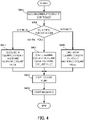
- Fig. 4 is a flowchart showing a control method by the controller 201.
- the controller 201 NC machine
- the M code in the machining program 214 is loaded, and it is determined which one of the half-wet machining mode 211, the wet machining mode 212, and the dry machining mode 213 is selected as the mode for supplying the coolant.
- the process advances to step S409 to open both the cleaning coolant valve 203 and the machining coolant valve 204.
- step S411 the process advances to step S411 to close both the cleaning coolant valve 203 and the machining coolant valve 204. If the half-wet machining mode 211 is selected, the process advances to step S407 to open the cleaning coolant valve 203 and close the machining coolant valve 204.
- step S413 the process advances to step S413 to start the coolant pump 202. Also, in step S415, the tool 210 and the work 220 are driven in accordance with the machining program, thereby starting machining.
- the chips 230 in the non-machining area can be removed without supplying the coolant to the machining area.
- the coolant is supplied to a portion where the chips can be removed without applying the coolant to the work
- the chips can be removed at an appropriate timing. More specifically, supply to the machining point + supply to other structures, supply only to the machining point, or supply only to walls and other structures is selected by the M code on the program, the channel is switched based on the selection result, and the supply destination of the coolant can be switched in accordance with machining.
- the controller may perform switching between only two modes, that is, the half-wet machining mode and the wet machining mode.
- the controller may perform switching between only two modes, that is, the half-wet machining mode and the dry machining mode.
- the machine tool 200 may include a camera (not shown), and in the half-wet machining mode 211, control may be performed to supply the coolant when the chips 230 are detected by the camera.
- FIG. 5 is a view for explaining the functional configuration of the machine tool 500 according to this example embodiment.
- the machine tool 500 according to this example embodiment is different from the second example embodiment in that the machine tool includes a coolant nozzle 503 capable of changing the ejection direction of a coolant when the coolant from a coolant pump 202 is ejected into the machine tool 500.
- a controller 501 includes a nozzle controller 515 that controls the coolant nozzle 503.
- the rest of the components and operations is the same as in the second example embodiment.
- the same reference numerals denote the same components and operations, and a detailed description thereof will be omitted.
- the nozzle controller 515 of the controller 501 controls the coolant nozzle 503, thereby ejecting the coolant to both a non-machining area 205 and a machining area 206 in a wet machining mode 212. Additionally, the nozzle controller 515 controls the coolant pump 202, thereby supplying no coolant to either the machining area 206 or the non-machining area 205 in a dry machining mode 213. That is, in the dry machining mode 213, the coolant pump 202 is stopped. In a half-wet machining mode 211, the controller 501 controls the direction of the coolant nozzle 503 such that the coolant is ejected to the non-machining area 205 to remove chips 230 but not to the machining area 206.
- the chips 230 in the non-machining area can be removed without supplying the coolant to the machining area.
- FIG. 6 is a view for explaining the functional configuration of the machine tool 600 according to this example embodiment.
- the machine tool 600 according to this example embodiment is different from the second example embodiment in that the machine tool includes a cleaning coolant pump 603 that supplies a coolant to a non-machining area, and a machining coolant pump 604 that supplies a coolant to a machining area.
- a controller 601 includes a pump controller 615 that controls the pumps. The rest of the components and operations is the same as in the second example embodiment. Hence, the same reference numerals denote the same components and operations, and a detailed description thereof will be omitted.
- the pump controller 615 turns off the machining coolant pump 604, and turns on a base coolant pump 209 and the cleaning coolant pump 603.
- the pump controller 615 turns on the base coolant pump 209, the machining coolant pump 604, and the cleaning coolant pump 603.
- the pump controller 615 controls the pumps to turn on the base coolant pump 209 and turn off the machining coolant pump 604 and the cleaning coolant pump 603.
- the present invention is applicable to a system including a plurality of devices or a single apparatus.
- the present invention is also applicable even when an information processing program for implementing the functions of example embodiments is supplied to the system or apparatus directly or from a remote site.
- the present invention also incorporates the program installed in a computer to implement the functions of the present invention by the computer, a medium storing the program, and a WWW (World Wide Web) server that causes a user to download the program.
- the present invention incorporates at least a non-transitory computer readable medium storing a program that causes a computer to execute steps S401 to S413 included in the above-described example embodiments.
Landscapes
- Engineering & Computer Science (AREA)
- Mechanical Engineering (AREA)
- Human Computer Interaction (AREA)
- Manufacturing & Machinery (AREA)
- Physics & Mathematics (AREA)
- General Physics & Mathematics (AREA)
- Automation & Control Theory (AREA)
- Auxiliary Devices For Machine Tools (AREA)
Abstract
Description
- This application is based upon and claims the benefit of priority from
Japanese patent application No. 2020-011804, filed on January 28, 2020 - The present invention relates to a machine tool, and a control apparatus and a control method thereof.
- In the above technical field,
patent literature 1 discloses a machine tool including a machining coolant supply path that supplies a coolant to a machining area by a tool, and a tool connecting portion cleaning coolant supply path that supplies a coolant to a connecting portion area between a spline and a tool at the time of tool exchange. - Patent literature 1:
Japanese Patent Laid-Open No. 2007-152489 - However, the technique described in the above literature uses control for always supplying the coolant to the machining area in machining. It is therefore impossible to meet a user's requirement that dry machining is performed without supplying a coolant to a work or tool, thereby reducing temperature variations in the tool and improving the tool life. On the other hand, if only control is performed not to supply a coolant, the driving load on the driving shaft may be excessive due to chips generated by machining, and the machine may stop with an alarm.
- The present invention enables to provide a technique of solving the above-described problem.
- One example aspect of the invention provides a machine tool that performs machining for a work using a tool, comprising
- a controller that performs mode switching between
- a half-wet machining mode in which, in addition to a base coolant, a coolant is supplied to a non-machining area to remove chips in the machine tool during machining, and no coolant is supplied to a machining area, and
- at least one of a wet machining mode in which the coolant is supplied to the machining area and a dry machining mode in which a coolant other than the base coolant is not supplied into the machine tool.
- Another example aspect of the invention provides a control apparatus of a machine tool that performs machining for a work using a tool, wherein the control apparatus performs mode switching between
- a half-wet machining mode in which a coolant is supplied to a non-machining area to remove chips in the machine tool during machining, and no coolant is supplied to a machining area, and
- at least one of a wet machining mode in which the coolant is supplied to the machining area and a dry machining mode in which no coolant is supplied into the machine tool.
- Still other example aspect of the invention provides a control method of a machine tool that performs machining for a work using a tool, comprising
- performing mode switching between
- a half-wet machining mode in which a coolant is supplied to a non-machining area to remove chips in the machine tool during machining, and no coolant is supplied to a machining area, and
- at least one of a wet machining mode in which the coolant is supplied to the machining area and a dry machining mode in which no coolant is supplied into the machine tool.
- According to the present invention, it is possible to perform cleaning in the machine while meeting the user's requirement to perform machining without supplying a coolant to a work or a tool.
-
-
Fig. 1 is a block diagram showing the functional configuration of a machine tool according to the first example embodiment of the present invention; -
Fig. 2 is a block diagram showing the functional configuration of a machine tool according to the second example embodiment of the present invention; -
Fig. 3 is a view showing an example of the machining program of the machine tool according to the second example embodiment of the present invention; -
Fig. 4 is a flowchart showing the procedure of processing of the machine tool according to the second example embodiment of the present invention; -
Fig. 5 is a block diagram showing the functional configuration of a machine tool according to the third example embodiment of the present invention; and -
Fig. 6 is a block diagram showing the functional configuration of a - Example embodiments of the present invention will now be described in detail with reference to the drawings. It should be noted that the relative arrangement of the components, the numerical expressions and numerical values set forth in these example embodiments do not limit the scope of the present invention unless it is specifically stated otherwise.
- A
machine tool 100 according to the first example embodiment of the present invention will be described with reference toFig. 1 . As shown inFig. 1 , themachine tool 100 performs machining of awork 120 using atool 110, and includes acontroller 101 that controls coolant supply. - The
controller 101 performs mode switching between a half-wet machining mode 111 and amachining mode 112 that is at least one of a wet machining mode and a dry machining mode. The half-wet machining mode 111 is a mode in which a coolant is supplied to remove chips in the machine tool during machining, and no coolant is supplied to a machining area. The wet machining mode is a mode in which a coolant is supplied to a machining area during machining. The dry machining mode is a mode in which no coolant is supplied into the machine tool during machining. - With the above-described configuration, even in the dry machining mode, chips in the machine tool can be cleaned by the coolant, and switching with another mode can be performed.
- A
machine tool 200 according to the second example embodiment of the present invention will be described next with reference toFig. 2. Fig. 2 is a block diagram for explaining the functional configuration of themachine tool 200 according to this example embodiment. - The
machine tool 200 is an apparatus for machining awork 220 using atool 210. Themachine tool 200 includes acoolant pump 202 that supplies a coolant to cool thetool 210 or thework 220 or removechips 230, and acontroller 201 that controls the supply of the coolant. In addition, themachine tool 200 also separately includes abase coolant pump 209 configured to supply a base coolant to the floor. Note thatFig. 2 shows two types of coolant pumps. However, coolant pumps may be provided in accordance with the use purpose of coolants (a spindle coolant, a through-spindle coolant, a shower coolant, a base coolant, and the like). - The
controller 201 performs mode switching between a half-wet machining mode 211, awet machining mode 212, and adry machining mode 213, and avalve controller 215 controls valves. The half-wet machining mode 211 is a mode in which a coolant is supplied to anon-machining area 205 to remove thechips 230 in themachine tool 200 during machining, and no coolant is supplied to amachining area 206. The non-machining area is, for example, an area on an APC (Automatic Pallet Changer) side. Thewet machining mode 212 is a mode in which a coolant is supplied to themachining area 206 during machining. Thedry machining mode 213 is a mode in which no coolant is supplied into themachine tool 200 during machining. - In the
wet machining mode 212, the coolant is supplied to the machining area during machining, thereby suppressing an increase of the temperature of thetool 210 or thework 220. Thedry machining mode 213 is a mode to be used by a user who wants to suppress the use amount of the coolant while prolonging the life of thetool 210 by stopping the supply of the coolant into themachine tool 200 to make the temperature change of thetool 210 moderate during machining. The half-wet machining mode 211 is a mode to be used by a user who wants to supply the coolant to remove thechips 230 in themachine tool 200 during machining but not to supply the coolant to themachining area 206 to prolong the life of thetool 210. - There are provided two types of coolant supply paths from the
coolant pump 202. These are asupply path 207 for non-machining area, which supplies the coolant from thecoolant pump 202 to thenon-machining area 205, and asupply path 208 for machining area, which supplies the coolant to themachining area 206. The supply paths are provided with a cleaningcoolant valve 203 and amachining coolant valve 204, respectively. - The
valve controller 215 opens both thecleaning coolant valve 203 and themachining coolant valve 204 in thewet machining mode 212, and closes both thecleaning coolant valve 203 and themachining coolant valve 204 in thedry machining mode 213. In the half-wet machining mode 211, thevalve controller 215 closes themachining coolant valve 204 and opens the cleaningcoolant valve 203. - More specifically, the
controller 201 is an NC machine (Numerical Control Machine), and executes amachining program 214 that is an NC program described by the user. Mode switching between the half-wet machining mode 211, thewet machining mode 212, and thedry machining mode 213 is thus performed. More specifically, M codes (Machine codes) corresponding to the above-described three modes are prepared in advance, and these M codes (for example, M90: Wet Mode, M91: Dry Mode, and M92: Half Wet Mode) are designated, thereby controlling the valves. That is, thecontroller 201 performs control based on the code of the machining program prepared in advance for at least one of the half-wet machining mode 211, thewet machining mode 212, and thedry machining mode 213.Fig. 3 shows an example of themachining program 214. InFig. 3 , "ceiling shower" means supplying the coolant from a plurality of nozzles on the ceiling to the machining area or the non-machining area, like shower. -
Fig. 4 is a flowchart showing a control method by thecontroller 201. First, in step S401, the controller 201 (NC machine) loads themachining program 214. Next, in step S405, the M code in themachining program 214 is loaded, and it is determined which one of the half-wet machining mode 211, thewet machining mode 212, and thedry machining mode 213 is selected as the mode for supplying the coolant. As a result, if thewet machining mode 212 is selected, the process advances to step S409 to open both the cleaningcoolant valve 203 and themachining coolant valve 204. If thedry machining mode 213 is selected, the process advances to step S411 to close both the cleaningcoolant valve 203 and themachining coolant valve 204. If the half-wet machining mode 211 is selected, the process advances to step S407 to open the cleaningcoolant valve 203 and close themachining coolant valve 204. - Then, the process advances to step S413 to start the
coolant pump 202. Also, in step S415, thetool 210 and thework 220 are driven in accordance with the machining program, thereby starting machining. - As described above, according to this example embodiment, the
chips 230 in the non-machining area can be removed without supplying the coolant to the machining area. When machining itself is performed as dry machining, and the coolant is supplied to a portion where the chips can be removed without applying the coolant to the work, the chips can be removed at an appropriate timing. More specifically, supply to the machining point + supply to other structures, supply only to the machining point, or supply only to walls and other structures is selected by the M code on the program, the channel is switched based on the selection result, and the supply destination of the coolant can be switched in accordance with machining. - Note that in this example embodiment, switching between three modes, that is, the half-wet machining mode, the wet machining mode, and the dry machining mode has been described. However, the controller may perform switching between only two modes, that is, the half-wet machining mode and the wet machining mode. Alternatively, the controller may perform switching between only two modes, that is, the half-wet machining mode and the dry machining mode. Also, the
machine tool 200 may include a camera (not shown), and in the half-wet machining mode 211, control may be performed to supply the coolant when thechips 230 are detected by the camera. - A
machine tool 500 according to the third example embodiment of the present invention will be described next with reference toFig. 5. Fig. 5 is a view for explaining the functional configuration of themachine tool 500 according to this example embodiment. Themachine tool 500 according to this example embodiment is different from the second example embodiment in that the machine tool includes acoolant nozzle 503 capable of changing the ejection direction of a coolant when the coolant from acoolant pump 202 is ejected into themachine tool 500. Also different is that acontroller 501 includes anozzle controller 515 that controls thecoolant nozzle 503. The rest of the components and operations is the same as in the second example embodiment. Hence, the same reference numerals denote the same components and operations, and a detailed description thereof will be omitted. - The
nozzle controller 515 of thecontroller 501 controls thecoolant nozzle 503, thereby ejecting the coolant to both anon-machining area 205 and amachining area 206 in awet machining mode 212. Additionally, thenozzle controller 515 controls thecoolant pump 202, thereby supplying no coolant to either themachining area 206 or thenon-machining area 205 in adry machining mode 213. That is, in thedry machining mode 213, thecoolant pump 202 is stopped. In a half-wet machining mode 211, thecontroller 501 controls the direction of thecoolant nozzle 503 such that the coolant is ejected to thenon-machining area 205 to removechips 230 but not to themachining area 206. - As described above, according to this example embodiment, the
chips 230 in the non-machining area can be removed without supplying the coolant to the machining area. - A
machine tool 600 according to the fourth example embodiment of the present invention will be described next with reference toFig. 6. Fig. 6 is a view for explaining the functional configuration of themachine tool 600 according to this example embodiment. Themachine tool 600 according to this example embodiment is different from the second example embodiment in that the machine tool includes a cleaningcoolant pump 603 that supplies a coolant to a non-machining area, and amachining coolant pump 604 that supplies a coolant to a machining area. Also different is that acontroller 601 includes apump controller 615 that controls the pumps. The rest of the components and operations is the same as in the second example embodiment. Hence, the same reference numerals denote the same components and operations, and a detailed description thereof will be omitted. - In a half-wet machining mode, the
pump controller 615 turns off themachining coolant pump 604, and turns on abase coolant pump 209 and the cleaningcoolant pump 603. In a wet machining mode, thepump controller 615 turns on thebase coolant pump 209, themachining coolant pump 604, and the cleaningcoolant pump 603. In a dry machining mode, thepump controller 615 controls the pumps to turn on thebase coolant pump 209 and turn off themachining coolant pump 604 and the cleaningcoolant pump 603. - This can obtain the same effects as in the second example embodiment.
- While the invention has been particularly shown and described with reference to example embodiments thereof, the invention is not limited to these example embodiments. It will be understood by those of ordinary skill in the art that various changes in form and details may be made therein without departing from the spirit and scope of the present invention as defined by the claims. A system or apparatus including any combination of the individual features included in the respective example embodiments may be incorporated in the scope of the present invention.
- The present invention is applicable to a system including a plurality of devices or a single apparatus. The present invention is also applicable even when an information processing program for implementing the functions of example embodiments is supplied to the system or apparatus directly or from a remote site. Hence, the present invention also incorporates the program installed in a computer to implement the functions of the present invention by the computer, a medium storing the program, and a WWW (World Wide Web) server that causes a user to download the program. Especially, the present invention incorporates at least a non-transitory computer readable medium storing a program that causes a computer to execute steps S401 to S413 included in the above-described example embodiments.
Claims (7)
- A machine tool that performs machining for a work using a tool, comprisinga controller that performs mode switching betweena half-wet machining mode in which, in addition to a base coolant, a coolant is supplied to a non-machining area to remove chips in the machine tool during machining, and no coolant is supplied to a machining area, andat least one of a wet machining mode in which the coolant is supplied to the machining area and a dry machining mode in which a coolant other than the base coolant is not supplied into the machine tool.
- The machine tool according to claim 1, further comprising:a coolant pump;a first supply path that supplies the coolant from the coolant pump to the machining area; anda second supply path that supplies the coolant from the coolant pump to the non-machining area,wherein said controller controls valves to close a valve of said first supply path and open a valve of said second supply path in the half-wet machining mode, open the valve of said first supply path and the valve of said second supply path in the wet machining mode, and close the valve of said first supply path and the valve of said second supply path in the dry machining mode.
- The machine tool according to claim 1 or 2, further comprising:a coolant pump; anda nozzle that ejects the coolant from said coolant pump into the machine tool,wherein said controller controls a direction of the nozzle not to supply the coolant to the machining area and to supply the coolant to the non-machining area in the half-wet machining mode, and controls the direction of the nozzle to supply the coolant to the machining area and the non-machining area in the wet machining mode.
- The machine tool according to claim 1, further comprising:a base coolant pump;a machining coolant pump that supplies the coolant to the machining area; anda cleaning coolant pump that supplies the coolant to the non-machining area,wherein said controller controls the pumps to turn off said cleaning coolant pump and turn on said base coolant pump and said machining coolant pump in the half-wet machining mode, turn on said base coolant pump, said machining coolant pump, and said cleaning coolant pump in the wet machining mode, and turn on said base coolant pump and turn off said machining coolant pump and said cleaning coolant pump in the dry machining mode.
- The machine tool according to any one of claims 1 to 4, wherein said controller performs control based on a code of a machining program prepared in advance for at least one of the half-wet machining mode, the wet machining mode, and the dry machining mode.
- A control apparatus of a machine tool that performs machining for a work using a tool, wherein the control apparatus performs mode switching betweena half-wet machining mode in which a coolant is supplied to a non-machining area to remove chips in the machine tool during machining, and no coolant is supplied to a machining area, andat least one of a wet machining mode in which the coolant is supplied to the machining area and a dry machining mode in which no coolant is supplied into the machine tool.
- A control method of a machine tool that performs machining for a work using a tool, comprisingperforming mode switching betweena half-wet machining mode in which a coolant is supplied to a non-machining area to remove chips in the machine tool during machining, and no coolant is supplied to a machining area, andat least one of a wet machining mode in which the coolant is supplied to the machining area and a dry machining mode in which no coolant is supplied into the machine tool.
Applications Claiming Priority (2)
| Application Number | Priority Date | Filing Date | Title |
|---|---|---|---|
| JP2020011804A JP6777829B1 (en) | 2020-01-28 | 2020-01-28 | Machine tools and their control devices and control methods |
| PCT/JP2021/000084 WO2021153166A1 (en) | 2020-01-28 | 2021-01-05 | Machine tool, and control device and control method for same |
Publications (3)
| Publication Number | Publication Date |
|---|---|
| EP4098397A1 true EP4098397A1 (en) | 2022-12-07 |
| EP4098397A4 EP4098397A4 (en) | 2023-07-19 |
| EP4098397B1 EP4098397B1 (en) | 2026-04-15 |
Family
ID=72916129
Family Applications (1)
| Application Number | Title | Priority Date | Filing Date |
|---|---|---|---|
| EP21748347.8A Active EP4098397B1 (en) | 2020-01-28 | 2021-01-05 | Machine tool, and control device and control method for same |
Country Status (5)
| Country | Link |
|---|---|
| US (1) | US12459070B2 (en) |
| EP (1) | EP4098397B1 (en) |
| JP (1) | JP6777829B1 (en) |
| CN (1) | CN115023315A (en) |
| WO (1) | WO2021153166A1 (en) |
Families Citing this family (1)
| Publication number | Priority date | Publication date | Assignee | Title |
|---|---|---|---|---|
| JP7249472B1 (en) * | 2022-07-27 | 2023-03-30 | ヤマザキマザック株式会社 | COOLANT SUPPLY DEVICE, MACHINE TOOL, COOLANT SUPPLY METHOD TO MACHINE TOOL, AND PROGRAM |
Family Cites Families (22)
| Publication number | Priority date | Publication date | Assignee | Title |
|---|---|---|---|---|
| JPS5844111U (en) * | 1981-09-21 | 1983-03-24 | 豊田工機株式会社 | Boring processing equipment |
| JPH0847839A (en) * | 1994-08-02 | 1996-02-20 | Makino Milling Mach Co Ltd | Machine tools capable of processing various chips |
| US5586848A (en) * | 1995-05-02 | 1996-12-24 | The Gleason Works | Machine tool chip removal system |
| JPH10180585A (en) * | 1996-11-06 | 1998-07-07 | Makino Milling Mach Co Ltd | Machine tools with automatic chip removal equipment |
| JP3549741B2 (en) * | 1998-09-08 | 2004-08-04 | 日本スピードショア株式会社 | Atomizer supply device |
| EP1112142A1 (en) | 1998-09-09 | 2001-07-04 | The Gleason Works | Apparatus for chip removal |
| JP2002066871A (en) * | 2000-09-04 | 2002-03-05 | Enshu Ltd | Processing method and ultra-fine mist generation device, work cooling method, spindle cooling method |
| JP2002103133A (en) * | 2000-09-27 | 2002-04-09 | Nachi Fujikoshi Corp | Broaching machine |
| JP2002129176A (en) * | 2000-10-27 | 2002-05-09 | Makino Milling Mach Co Ltd | Processing liquid and processing method using the processing liquid |
| JP2003019637A (en) * | 2001-07-09 | 2003-01-21 | Fuji Heavy Ind Ltd | Coolant cleaning equipment for machine tools |
| JP2003089036A (en) * | 2001-09-18 | 2003-03-25 | Citizen Watch Co Ltd | Mist generation system, mist mixing device, mist distribution device, and numerical control machine tool for semi-dry process |
| JP2005335015A (en) * | 2004-05-27 | 2005-12-08 | Toyota Motor Corp | Preset screw, tool holder and fluid supply method |
| JP2007152489A (en) | 2005-12-05 | 2007-06-21 | Fanuc Ltd | Coolant supply device of machine tool |
| JP2008213099A (en) * | 2007-03-06 | 2008-09-18 | Nsk Ltd | Broaching machine |
| EP2756920B1 (en) * | 2011-09-16 | 2019-03-27 | Makino Milling Machine Co. Ltd. | Coolant supply device |
| JP6625795B2 (en) * | 2014-09-30 | 2019-12-25 | ファナック株式会社 | Cutting fluid injection device |
| JP6653677B2 (en) | 2017-03-24 | 2020-02-26 | Dmg森精機株式会社 | Chip conveyors and machine tools |
| JP7061890B2 (en) * | 2018-02-20 | 2022-05-02 | シチズン時計株式会社 | Machine Tools |
| JP2020006462A (en) * | 2018-07-06 | 2020-01-16 | Dgshape株式会社 | Cleaning jig and cleaning mechanism for wet processing equipment |
| JP7056426B2 (en) | 2018-07-17 | 2022-04-19 | 日本製鉄株式会社 | Escape prevention device |
| US11273531B2 (en) * | 2018-09-10 | 2022-03-15 | Fanuc America Corporation | Smart coolant pump |
| CN109514337B (en) | 2018-11-12 | 2021-07-23 | 西安精雕软件科技有限公司 | Chip removing system capable of rapidly realizing dry and wet processing switching and using method thereof |
-
2020
- 2020-01-28 JP JP2020011804A patent/JP6777829B1/en active Active
-
2021
- 2021-01-05 EP EP21748347.8A patent/EP4098397B1/en active Active
- 2021-01-05 CN CN202180011433.5A patent/CN115023315A/en active Pending
- 2021-01-05 WO PCT/JP2021/000084 patent/WO2021153166A1/en not_active Ceased
- 2021-01-05 US US17/759,493 patent/US12459070B2/en active Active
Also Published As
| Publication number | Publication date |
|---|---|
| EP4098397B1 (en) | 2026-04-15 |
| US20240217044A1 (en) | 2024-07-04 |
| JP6777829B1 (en) | 2020-10-28 |
| EP4098397A4 (en) | 2023-07-19 |
| WO2021153166A1 (en) | 2021-08-05 |
| US12459070B2 (en) | 2025-11-04 |
| JP2021115682A (en) | 2021-08-10 |
| CN115023315A (en) | 2022-09-06 |
Similar Documents
| Publication | Publication Date | Title |
|---|---|---|
| DE102015013581B4 (en) | Numerical control | |
| CN107305361B (en) | Numerical controller for reducing power consumption in non-cutting state | |
| CN105729237A (en) | Cutting fluid supply system to machine tool | |
| EP4098397B1 (en) | Machine tool, and control device and control method for same | |
| KR101479885B1 (en) | Power-supply management device and machine tool provided with power-supply management device | |
| CN104793559A (en) | NC program generating apparatus considering power saving | |
| US10108171B2 (en) | Numerical controller capable of specifying halt point | |
| KR101777476B1 (en) | Electric discharge machine | |
| US10635090B2 (en) | Program generating apparatus and program generating method | |
| JP2011148047A (en) | Tool cleaning device for machine tool | |
| KR970069210A (en) | Method and apparatus for controlling machine tools, especially EDM machines | |
| WO2019215787A1 (en) | Machine tool | |
| US5043550A (en) | Wire cut electric discharge machine | |
| JP3488801B2 (en) | Machine tool control method and device | |
| CN107598922B (en) | Multitask teaching control method and system | |
| JP5482219B2 (en) | Tool cleaning equipment for machine tools | |
| CN115734838B (en) | machine tool | |
| JP6181709B2 (en) | Machine tool controller | |
| JP4627821B2 (en) | Laser processing apparatus and interrupt processing method thereof | |
| JP4859467B2 (en) | How to restart a 2-spindle facing lathe | |
| JP2003089036A (en) | Mist generation system, mist mixing device, mist distribution device, and numerical control machine tool for semi-dry process | |
| KR20170109714A (en) | Cutting Apparatus Haing Injection Quantity Contol Part and Cutting Method | |
| KR19980038797A (en) | Alternative tool changer and method of horizontal machining center | |
| KR100537573B1 (en) | Coolant Spray Supply Equipment | |
| KR200243342Y1 (en) | a cutting fluid supply a feeding apparatus |
Legal Events
| Date | Code | Title | Description |
|---|---|---|---|
| STAA | Information on the status of an ep patent application or granted ep patent |
Free format text: STATUS: THE INTERNATIONAL PUBLICATION HAS BEEN MADE |
|
| PUAI | Public reference made under article 153(3) epc to a published international application that has entered the european phase |
Free format text: ORIGINAL CODE: 0009012 |
|
| STAA | Information on the status of an ep patent application or granted ep patent |
Free format text: STATUS: REQUEST FOR EXAMINATION WAS MADE |
|
| 17P | Request for examination filed |
Effective date: 20220711 |
|
| AK | Designated contracting states |
Kind code of ref document: A1 Designated state(s): AL AT BE BG CH CY CZ DE DK EE ES FI FR GB GR HR HU IE IS IT LI LT LU LV MC MK MT NL NO PL PT RO RS SE SI SK SM TR |
|
| DAV | Request for validation of the european patent (deleted) | ||
| DAX | Request for extension of the european patent (deleted) | ||
| A4 | Supplementary search report drawn up and despatched |
Effective date: 20230620 |
|
| RIC1 | Information provided on ipc code assigned before grant |
Ipc: B23Q 11/14 20060101ALI20230614BHEP Ipc: B23Q 11/10 20060101ALI20230614BHEP Ipc: B23Q 11/00 20060101AFI20230614BHEP |
|
| GRAP | Despatch of communication of intention to grant a patent |
Free format text: ORIGINAL CODE: EPIDOSNIGR1 |
|
| STAA | Information on the status of an ep patent application or granted ep patent |
Free format text: STATUS: GRANT OF PATENT IS INTENDED |
|
| INTG | Intention to grant announced |
Effective date: 20251222 |
|
| P01 | Opt-out of the competence of the unified patent court (upc) registered |
Free format text: CASE NUMBER: UPC_APP_0002923_4098397/2026 Effective date: 20260128 |
|
| GRAS | Grant fee paid |
Free format text: ORIGINAL CODE: EPIDOSNIGR3 |
|
| GRAA | (expected) grant |
Free format text: ORIGINAL CODE: 0009210 |
|
| STAA | Information on the status of an ep patent application or granted ep patent |
Free format text: STATUS: THE PATENT HAS BEEN GRANTED |
|
| AK | Designated contracting states |
Kind code of ref document: B1 Designated state(s): AL AT BE BG CH CY CZ DE DK EE ES FI FR GB GR HR HU IE IS IT LI LT LU LV MC MK MT NL NO PL PT RO RS SE SI SK SM TR |
|
| REG | Reference to a national code |
Ref country code: CH Ref legal event code: F10 Free format text: ST27 STATUS EVENT CODE: U-0-0-F10-F00 (AS PROVIDED BY THE NATIONAL OFFICE) Effective date: 20260415 |
|
| REG | Reference to a national code |
Ref country code: DE Ref legal event code: R096 Ref document number: 602021052120 Country of ref document: DE |