EP4098351A1 - A filtration system with a lifting arrangement for membranes - Google Patents
A filtration system with a lifting arrangement for membranes Download PDFInfo
- Publication number
- EP4098351A1 EP4098351A1 EP22176890.6A EP22176890A EP4098351A1 EP 4098351 A1 EP4098351 A1 EP 4098351A1 EP 22176890 A EP22176890 A EP 22176890A EP 4098351 A1 EP4098351 A1 EP 4098351A1
- Authority
- EP
- European Patent Office
- Prior art keywords
- membrane
- arm
- filtration system
- membranes
- gripper unit
- Prior art date
- Legal status (The legal status is an assumption and is not a legal conclusion. Google has not performed a legal analysis and makes no representation as to the accuracy of the status listed.)
- Granted
Links
Images



Classifications
-
- B—PERFORMING OPERATIONS; TRANSPORTING
- B01—PHYSICAL OR CHEMICAL PROCESSES OR APPARATUS IN GENERAL
- B01D—SEPARATION
- B01D65/00—Accessories or auxiliary operations, in general, for separation processes or apparatus using semi-permeable membranes
-
- B—PERFORMING OPERATIONS; TRANSPORTING
- B01—PHYSICAL OR CHEMICAL PROCESSES OR APPARATUS IN GENERAL
- B01D—SEPARATION
- B01D2313/00—Details relating to membrane modules or apparatus
- B01D2313/56—Specific mechanisms for loading the membrane in a module
-
- B—PERFORMING OPERATIONS; TRANSPORTING
- B01—PHYSICAL OR CHEMICAL PROCESSES OR APPARATUS IN GENERAL
- B01D—SEPARATION
- B01D2313/00—Details relating to membrane modules or apparatus
- B01D2313/57—Tools used for removal of membranes
Definitions
- the invention relates to filtration systems for food processing lines. More specifically, it is related to a filtration system comprising a membrane arrangement and to equipment and methods for replacing membranes in the membrane arrangement.
- membrane filtration is commonly used for processing and separating components in milk and other liquid food products. To assure that different components of e.g. milk are separated adequately, membranes need to be replaced at frequent intervals. How often depends on a number of factors, such as properties of the food product and quality of the membranes. A factor sometimes overlooked is that the membranes sometimes need to be replaced too soon due to damages caused during handling of the membranes.
- membrane housings are made to contain several membranes placed after one another. In this way, when the membranes are to be replaced these are pulled out of the membrane housing one by one, and thereafter new membranes are pushed one by one into the membrane housing.
- a filtration system comprising a membrane arrangement comprising membrane housings extending in a first direction and having openings that are located in a common plane and face a common area, and membranes arranged inside the membrane housings and configured to be replaced via the openings.
- the filtration system also comprises a lifting arrangement comprising a support frame having a beam that extends along the common plane and is provided vertically above the common area, and a gripper unit slidably attached to the beam and arranged to grip the membranes and transport the membranes in a direction along the common plane.
- An advantage with having the filtration system provided with the lifting arrangement is that membranes may be handled and inserted securely into the membrane housings, thereby reducing the risk of damaging the membranes.
- the membrane housings may be arranged in horizontal rows and vertical columns. This configuration provides for convenient and efficient operation of the lifting arrangement.
- the membranes may be spiral wound membranes that are arranged in groups in the membrane housings, where the membranes in each group are positioned after one another in the first direction.
- the beam may be provided with a groove to which the gripper unit is connected, for allowing the gripper unit to slide along the beam in the direction along the common plane. Having the beam provided with the groove provides for that the membrane can be reliably handled and moved in said direction.
- the gripper unit may be attached to the beam via a hoist unit, the hoist unit may comprise a motor arranged to vertically move the gripper unit together with a membrane held by the gripper unit.
- the gripper unit may comprise a pipe tong for gripping a membrane. Having the gripper unit embodied as a pipe tong provides for a reliable gripping mechanism that can easily be controlled for safe handling of the membranes.
- the gripper unit may comprise a first arm, a second arm, a third arm and a fourth arm, wherein the first arm may be connected to the second arm via a first rotational point, the third arm may be connected to the first arm via a second rotational point, the fourth arm may be connected to the second arm via a third rotational point, the third arm may be connected to the fourth arm via the fourth rotational point.
- a first membrane holder is attached to the fourth arm, and a second membrane holder is attached to the third arm, for allowing the first and second membrane holder to clamp the membrane when the second arm is pulled upwards.
- the gripper unit may comprise a locking device and a locking element, wherein the locking element may be rotationally connected to the second arm via a fifth rotational point, said locking device may further comprise a guiding element, fixedly attached and provided with a slanted top surface and a bottom surface recess, and a tilt element, rotationally attached via a tilt rotational point and provided with a slanted top surface and a bottom surface.
- the locking element further comprises a locking pin provided in a peripheral end of the locking element, such that: when the second arm is lowered the locking pin is introduced into the locking device and guided downwards via the slanted top surface of the tilt element and the slanted top surface of the guiding element; thereafter, when the second arm is lifted, the locking pin is caught in the bottom surface recess of the guiding element, thereby providing for that the first and second membrane holder are held apart; and thereafter, when the second arm is lowered and lifted, the locking pin is released from the bottom surface recess and pushed through between the guiding element and the tilt element by pushing the tilt element from a closed position to an open position via the bottom surface of the tilt element and out from the locking device.
- the gripper unit may be lowered down onto the membrane, and once being in contact with the membrane the locking pin can be released from the bottom surface recess such that the membrane is gripped, or clamped, between the first and second membrane holders. Put differently, the membrane may be gripped without any specific locking action being required by the operator.
- the support frame may be fixedly attached relative to the membrane arrangement.
- the support frame may be fixedly attached to the membrane housings.
- the support frame may be attached to the membrane housings via a first and a second pipe clamp.
- the filtration system may further comprise a support device arranged to be connected to one of the membrane housings at the opening of the membrane housing, and configured to support membranes that are pushed into or pulled out from the membrane housing.
- a support device arranged to be connected to one of the membrane housings at the opening of the membrane housing, and configured to support membranes that are pushed into or pulled out from the membrane housing.
- a lifting arrangement arranged to be fixedly attached relative to a membrane arrangement such that a filtration system according to the first aspect is formed, said lifting arrangement comprising a support frame having a beam that extends along the common plane and is provided vertically above the common area, and a gripper unit slidably attached to the beam and arranged to grip the membranes and to transport the membranes in a direction B along the common plane.
- An advantage with this second aspect is, in line with the first aspect, that the risk of damaging the membranes can be reduced, for example when retrofitting existing membrane arrangements with the lifting arrangement.
- the advantage is that the risk of damaging the membranes can be reduced.
- a filtration system 100 is illustrated by way of example.
- the filtration system 100 can form part of a food processing line for milk or other liquid food products.
- the filtration system 100 may, for example, be used for separating different components of milk such that lactose free milk can be produced, but also for removing bacteria and spores without the need to heat treat the food products.
- different membranes may be used, e.g. spiral wound membranes.
- the filtration system 100 can comprise a membrane arrangement 102 in turn comprising a number of membrane housings 104.
- the membrane housings 104 may be provided in horizontal layers placed on top of each other.
- the membrane housings 104 can be provided with openings 106 in one end to provide for that membranes inside the housing 104 can be replaced.
- the openings 106 may all face a common area 108 as illustrated such that an operator can replace membranes from one and the same side. Even though not illustrated, it is also an option to have some openings facing in an opposite direction such that there are two common areas in which the operator can replace the membranes. Further, it is also possible two have openings in both ends of the membrane housings 104.
- the openings 106 may be arranged in a common plane 109. Since the membrane housings 104 in the illustrated example are provided in a number of horizontal layers arranged on top of each other, the openings 106 are arranged in this common plane 109 in rows 124 and columns 122.
- a lifting arrangement 112 can be used.
- the lifting arrangement 112 may comprise a support frame 114 that in one end can be attached to the membrane arrangement 102 and in the other end support a beam 116.
- the beam 116 may be arranged such that it is parallel, or at least substantially parallel, with the common plane 109. This is advantageous in that a gripper unit 118 that is attached to the beam 116 can be moved along the beam 116 and thereby reach different columns 122 of the openings 106 of the membrane housings 104.
- a support device 120 may be used for holding the membrane 110 after this has been pulled out from the membrane housing 104, but before being gripped by the gripper unit 118.
- the support device 120 may be designed in different ways.
- the support device 120 can be made with an opening in one end such that this may be hooked onto one of the membrane housings 104.
- Fig. 2 illustrates the lifting arrangement 112 and the support device 120 in further detail.
- the lifting arrangement 112 may be attached to the membrane arrangement 102 by using first and second pipe clamps 126a, 126b. These clamps may be arranged around the membrane housings 104.
- An advantage with this is that the lifting arrangement 112 can be attached to an existing membrane arrangement 102 with no or few modifications needed.
- the gripper unit 118 which is generally illustrated in fig. 2 , may be moved along the beam 116 by having a groove 128 in a bottom section of the beam 116. By using this groove 128 in combination with a sliding member 129 held in the groove 128, the gripper unit 118 may be slided along the beam 116 by an operator.
- the gripper unit 118 may be attached to the beam 116 via a hoist unit 130 that can lift the gripper unit 118 vertically.
- the hoist unit 130 may be provided with a motor 131 such that a membrane 110 can be lifted and lowered reliably.
- the hoist unit 130 may in combination with the beam 116 provide for that a membrane 110 can be securely transported and aligned with the opening 106 before this is pushed into the membrane housing 104.
- the hoist unit 130 may be designed in different ways. Thus, even though the hoist unit 130 illustrated by way of example is provided with the motor 131, it is also possible to have the hoist unit 130 provided without a motor. For instance, the hoist unit 130 can be a manually operated chain telfer.
- the gripper unit 118 may be fully suspended by the hoist unit 130.
- the hoist unit 130 may be arranged vertically above the gripper unit 118. This may mean that the gripper unit 118 is not supported by any structure that is located vertically below the gripper unit 118. In this way space may be freed up below the gripper unit 118 when used for lifting membranes.
- the gripper unit 118 may be connected to the hoist unit 130 via a flexible connection element 140 such as a chain, a wire, a rope or similar.
- the support device 120 may have a first and a second guiding wall 132a, 132b.
- An advantage with these is that the membrane 110 can be guided into the opening 106 of the membrane housing 104 in a way such that the risk of damaging the membrane 110, due to non-alignment, can be reduced.
- the first and second guiding walls 132a, 132b can hold the membrane 110 after this has been pulled out via the opening 106 of the membrane housing 104 while the membrane is gripped by the gripper unit 118.
- the operator may first pull out the membrane 110 from the membrane housing 104 into the support device 120. Thereafter, the membrane 110 may be gripped by the gripper unit 118.
- the first and second guiding walls 132a, 132b which extend upwardly from ribs that form a base 132c of the support device 120, may be arranged such that the membrane 110 held in the support device 120 can be gripped by the gripper unit 118 from above.
- a height H of the first and second guiding walls 132a, 132b of the support device 120 in a gripping section 133 may be less than half a diameter D of an opening 135 of the support device 120 through which a membrane may be pushed.
- the height H of the first and second guiding walls 132a, 132b of the support device 120 may be declining towards an outer end of the support device 120.
- Fig. 3A and 3B illustrate an example of how the membrane 110 can be pulled out from the membrane arrangement 102.
- the membrane 110 can be pulled out from the membrane housing 104 into the support device 120.
- the membrane housings 104 may extend in a first direction A and the beam 116 may extend in a second direction B perpendicular, or at least substantially perpendicular, to the first direction A.
- the first direction A may be a horizontal direction.
- the membrane 110 is pulled out from the membrane housing 104 via the opening 106 into the support device 120.
- the gripper unit 118 may be held above and at a distance from the membrane 110 held in the support device 120.
- the gripper unit 118 may be lowered and the membrane 110 may be gripped by the gripper unit 118.
- the membrane 110 can be transported in the second direction B by being slided together with the gripper unit 118 along the beam 116.
- the membrane 110 may be dropped off by the gripper unit 118 in a drop off area 136.
- the gripper unit 118 may be transported to a pick-up area 138 in which a new membrane 134 may be picked up.
- the new membrane 134 may be picked up by lowering down the gripper unit 118 such that the new membrane 134 can be gripped.
- the gripper unit 118 and the membrane 110 can be transported by being slided along the beam 116 to the support device 120.
- the gripper unit 118 can be lowered such that the new membrane 134 is placed in the support device 120.
- the new membrane 134 can be released from the gripper unit 118.
- the new membrane 134 is aligned in the first direction A by the first and second guiding walls 132a, 132b and it can thus be pushed into the membrane housing 104 in a safe and secure manner.
- the membrane 110 can be replaced without using the support device 120.
- the membrane 110 may be pulled out halfway from the membrane housing 104 and while the membrane 110 is held in place by the membrane housing 104, possibly in combination with assistance from an operator supporting the membrane 110, the membrane 110 can be gripped by the gripper unit 118.
- a similar but reverse process may be used for introducing the new membrane 134 into the membrane housing 104.
- a section of the new membrane 134 can be pushed into the membrane housing 104 such that the new membrane 134 is held in place by the membrane housing 104, and thereafter the gripper unit 118 can be released from new membrane 134. Once released, the new membrane 134 can be fully pushed into the membrane housing 104.
- the gripper unit 118 may be linked to the hoist unit 130 via a chain 140 or similar.
- the hoist unit 130 may be held still and the gripper unit 118 may be lifted or lowered together with the membrane 110.
- Lowering or lifting the membrane 110 may be achieved by reducing or increasing a length of the chain 140 linking the two parts 118, 130. Having the chain 140 also provides for that the membrane 110 as well as the new membrane 134 can be moved in the first direction A such that e.g. the membrane 110 can be pushed into the membrane housing 104 before releasing the gripper unit 118.
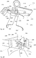
- Fig. 4A illustrates the gripper unit 118 by way of example.
- the example illustrated is a so-called pipe tong 219.
- the gripper unit 118 is illustrated in a release mode.
- the gripper unit 118 can comprise an attachment ring 200.
- a first arm 202 and a second arm 204 rotationally connected to each other is lifted such that these extend substantially vertical instead of substantially horizontally. Since the first arm 202 is rotationally connected to a third arm 206, placed below the first arm 202, and the second arm 204 is rotationally connected to a fourth arm 208, placed below the second arm 204, this will have the effect that in turn also the third arm 206 and the fourth arm 208 are changed from extending substantially horizontally to substantially vertically.
- the first arm 202 can be connected to the second arm 204 in a first rotational point 210
- the first arm 202 can be connected to the third arm 206 in a second rotational point 212
- the second arm 204 can be connected to the fourth arm 208 in a third rotational point 214
- the third and fourth arm 206, 208 can be connected to each other in a fourth rotational point 216.
- a fifth rotational point 218 is provided above the fourth rotational point 216. Via this fifth rotational point 218, the attachment ring 200 is connected to the second arm 204.
- a first membrane holder 220 can be attached to the fourth arm 208 below the fourth rotational point 216, and a second membrane holder 222 can be attached to the third arm 206 below the fourth rotational point 216.
- the first and second membrane holders 220, 222 will move towards one another and thereby providing for that the membrane 110 can be securely held between the two.
- the gripper unit 118 is referred to be in a grip mode.
- the hoist unit 130 and the gripper unit 118 can be slided along the beam 116 by the operator.
- a handle 223 may be provided on the gripper unit 118.
- a locking device 224 can be provided.
- the locking device 224 which is further illustrated in fig. 4B , may interact with a locking element 226 provided with a protrusion 228 in a peripheral end.
- the protrusion 228 may have the form of a pin, and may be referred to as a locking pin 228.
- the locking element 226 can be connected to the second arm 204 via the fifth rotational point 218.
- the locking element 226 may be L-shaped. An effect of this L-shape is that a momentum will be formed that will provide for that the protrusion 228 is pushed in accordance with the momentum formed by the L-shape. In this particular example, the protrusion 228 is pushed to the right.
- Fig. 4B illustrates the locking device 224 in further detail.
- the locking device 224 can comprise a guiding element 230, which may be fixedly attached to a rear side 231 of the locking device 224.
- the guiding element 230 may comprise a bottom surface recess 232 arranged to hold the protrusion 228.
- a tilt element 234 can also be provided. As the name suggests, the tilt element 234 can be tilted between a closed position I, as illustrated, and an open position II. To provide for that the tilt element 234 is in the closed position I when not forced into the open position II, a spring 236 attached to a side wall 238 can be provided. In a lower end of the tilt element 234, a tilt rotational point 240 may be provided.
- the protrusion 228 of the locking element 226 when lowered into the locking device 224 can be guided via a slanted top surface 242 of the tilt element 234 and a slanted top surface 244 of the guiding element 230 into a position A.
- the L-shape of the locking element 226 can provide for that the protrusion 228 is pushed towards the slanted top surfaces 242, 244.
- the protrusion 228 is introduced into the bottom surface recess 232 of the guiding element 230, herein denoted as position B.
- the locking element 226 provides for that the gripper unit 118 is in the release mode, i.e. the first and second membrane members 220, 222 are held apart as illustrated in fig. 4A .
- the protrusion 228 When having the protrusion 228 placed in the bottom surface recess 232, i.e. position B, and lowering the gripper unit 118 onto the membrane 110, the protrusion 228 will be released from the bottom surface recess 232, move down and thereafter into a position between the guiding element 230 and the tilt element 234, herein denoted position C.
- the tilt element 234 When lifting the gripper unit 118, the tilt element 234 can be tilted from the closed position I to the open position II when the protrusion 228 engages the bottom surface 246 of the tilt element 234, such that the protrusion 228 is let through between the guiding element 230 and the tilt element 234.
- the gripper unit 118 As an effect of that the protrusion 228 is let through, the gripper unit 118 is no longer locked in the release mode, but can enter the grip mode and thereby grip the membrane 110.
- Fig. 5 is a flowchart illustrating a method 300 for replacing membranes 110 in the filtration system 100 by way of example.
- the method can comprise
Landscapes
- Chemical & Material Sciences (AREA)
- Chemical Kinetics & Catalysis (AREA)
- Separation Using Semi-Permeable Membranes (AREA)
Abstract
Description
- The invention relates to filtration systems for food processing lines. More specifically, it is related to a filtration system comprising a membrane arrangement and to equipment and methods for replacing membranes in the membrane arrangement.
- Today, membrane filtration is commonly used for processing and separating components in milk and other liquid food products. To assure that different components of e.g. milk are separated adequately, membranes need to be replaced at frequent intervals. How often depends on a number of factors, such as properties of the food product and quality of the membranes. A factor sometimes overlooked is that the membranes sometimes need to be replaced too soon due to damages caused during handling of the membranes.
- To facilitate the handling of the membranes for the operator and thereby reducing the risk of damages, which can reduce the operational lifetime of the membrane, the membranes are often produced in lengths such that these can be handled by an operator. As an effect of this, it is common that membrane housings are made to contain several membranes placed after one another. In this way, when the membranes are to be replaced these are pulled out of the membrane housing one by one, and thereafter new membranes are pushed one by one into the membrane housing.
- Even though the membranes are produced in lengths such that these can be efficiently and safely handled by operators, there is still a risk of damaging the membranes when pushing these into the membrane housings.
- It is an object of the invention to at least partly overcome one or more of the above-identified limitations of the prior art. In particular, it is an object to provide a filtration system where the risk of damaging the membranes when pushing these into the membranes housings is mitigated.
- According to a first aspect a filtration system is provided, said filtration system comprising a membrane arrangement comprising membrane housings extending in a first direction and having openings that are located in a common plane and face a common area, and membranes arranged inside the membrane housings and configured to be replaced via the openings. The filtration system also comprises a lifting arrangement comprising a support frame having a beam that extends along the common plane and is provided vertically above the common area, and a gripper unit slidably attached to the beam and arranged to grip the membranes and transport the membranes in a direction along the common plane.
- An advantage with having the filtration system provided with the lifting arrangement is that membranes may be handled and inserted securely into the membrane housings, thereby reducing the risk of damaging the membranes.
- The membrane housings may be arranged in horizontal rows and vertical columns. This configuration provides for convenient and efficient operation of the lifting arrangement.
- The membranes may be spiral wound membranes that are arranged in groups in the membrane housings, where the membranes in each group are positioned after one another in the first direction. An advantage of having several membranes in each membrane housing is that the membranes may be produced at a length easy to handle for the operator when using the lifting arrangement. This provides for that the risk of damaging the membranes can be further reduced.
- The beam may be provided with a groove to which the gripper unit is connected, for allowing the gripper unit to slide along the beam in the direction along the common plane. Having the beam provided with the groove provides for that the membrane can be reliably handled and moved in said direction.
- The gripper unit may be attached to the beam via a hoist unit, the hoist unit may comprise a motor arranged to vertically move the gripper unit together with a membrane held by the gripper unit.
- The gripper unit may comprise a pipe tong for gripping a membrane. Having the gripper unit embodied as a pipe tong provides for a reliable gripping mechanism that can easily be controlled for safe handling of the membranes.
- The gripper unit may comprise a first arm, a second arm, a third arm and a fourth arm, wherein the first arm may be connected to the second arm via a first rotational point, the third arm may be connected to the first arm via a second rotational point, the fourth arm may be connected to the second arm via a third rotational point, the third arm may be connected to the fourth arm via the fourth rotational point. A first membrane holder is attached to the fourth arm, and a second membrane holder is attached to the third arm, for allowing the first and second membrane holder to clamp the membrane when the second arm is pulled upwards.
- The gripper unit may comprise a locking device and a locking element, wherein the locking element may be rotationally connected to the second arm via a fifth rotational point, said locking device may further comprise a guiding element, fixedly attached and provided with a slanted top surface and a bottom surface recess, and a tilt element, rotationally attached via a tilt rotational point and provided with a slanted top surface and a bottom surface. The locking element further comprises a locking pin provided in a peripheral end of the locking element, such that: when the second arm is lowered the locking pin is introduced into the locking device and guided downwards via the slanted top surface of the tilt element and the slanted top surface of the guiding element; thereafter, when the second arm is lifted, the locking pin is caught in the bottom surface recess of the guiding element, thereby providing for that the first and second membrane holder are held apart; and thereafter, when the second arm is lowered and lifted, the locking pin is released from the bottom surface recess and pushed through between the guiding element and the tilt element by pushing the tilt element from a closed position to an open position via the bottom surface of the tilt element and out from the locking device.
- An advantage with having the locking device is that the gripper unit may be lowered down onto the membrane, and once being in contact with the membrane the locking pin can be released from the bottom surface recess such that the membrane is gripped, or clamped, between the first and second membrane holders. Put differently, the membrane may be gripped without any specific locking action being required by the operator.
- The support frame may be fixedly attached relative to the membrane arrangement. The support frame may be fixedly attached to the membrane housings. The support frame may be attached to the membrane housings via a first and a second pipe clamp. An advantage with having the support frame attached in this way is that the lifting arrangement can easily be mounted to an existing filtration system without introducing any new parts being in contact with the food product.
- The filtration system may further comprise a support device arranged to be connected to one of the membrane housings at the opening of the membrane housing, and configured to support membranes that are pushed into or pulled out from the membrane housing. An advantage with having the support device is that the membrane may pulled out from the membrane housing into the support device and thereafter, while being held in the support device, the membrane may be gripped by the gripper unit. Conversely, when inserting a new membrane, the membrane may be placed into the support device by the gripper unit, and after being released by the gripper unit, be pushed into the membrane housing. Thus, the combination of the lifting arrangement and the support device provides for that the membranes can be handled even more securely such that the risk of damaging these can be reduced.
- According to a second aspect it is provided a lifting arrangement arranged to be fixedly attached relative to a membrane arrangement such that a filtration system according to the first aspect is formed, said lifting arrangement comprising a support frame having a beam that extends along the common plane and is provided vertically above the common area, and a gripper unit slidably attached to the beam and arranged to grip the membranes and to transport the membranes in a direction B along the common plane.
- An advantage with this second aspect is, in line with the first aspect, that the risk of damaging the membranes can be reduced, for example when retrofitting existing membrane arrangements with the lifting arrangement.
- According to a third aspect it is provided a method for replacing membranes in a filtration system according to the first aspect, said method comprising
- a) attaching the support device to an opening of one of the membrane housings of the filtration system,
- b) pulling a membrane out from the membrane housing and into the support device,
- c) gripping and lifting the membrane with the gripper unit,
- d) moving the gripper unit with the membrane in the direction B along the common plane,
- e) lowering and releasing the membrane in a drop off area,
- f) repeating steps b) to e) until the membrane housing is empty,
- g) gripping and lifting, from a pick-up area, a new membrane with the gripper unit,
- h) sliding the gripping unit with the new membrane in the direction B along the common plane,
- i) lowering and releasing the new membrane in the support device,
- j) pushing the new membrane into the membrane housing,
- k) repeating steps g) to k) until the membrane housing is full with new membranes,
- l) removing the support device from the opening of the membrane housing, and
- m) repeating steps a) to I) for a number of membrane housings of the filtration system.
- Also for this third aspect, the advantage is that the risk of damaging the membranes can be reduced.
- The features and advantages discussed in relation to the first aspect also apply to the second and third aspects even though not explicitly mentioned in relation to these aspects.
- Still other objectives, features, aspects and advantages of the invention will appear from the following detailed description as well as from the drawings.
- Embodiments of the invention will now be described, by way of example, with reference to the accompanying schematic drawings, in which
-
Fig. 1 is a perspective view of a filtration system. -
Fig. 2 is a detailed perspective of a lifting arrangement of the filtration system. -
Fig. 3A generally illustrates the filtration system from above when a membrane is pulled out from a membrane housing. -
Fig. 3B generally illustrates the filtration system from above when the membrane is moved, by using a carrier unit, from a membrane housing towards a drop off area. -
Fig. 4A illustrates the carrier unit in further detail. -
Fig. 4B illustrates a locking device of the carrier unit. -
Fig. 5 is a flow chart illustrating a method for replacing a membrane. - With reference to
Fig. 1 , afiltration system 100 is illustrated by way of example. Thefiltration system 100 can form part of a food processing line for milk or other liquid food products. Thefiltration system 100 may, for example, be used for separating different components of milk such that lactose free milk can be produced, but also for removing bacteria and spores without the need to heat treat the food products. To achieve this, different membranes may be used, e.g. spiral wound membranes. - The
filtration system 100 can comprise amembrane arrangement 102 in turn comprising a number ofmembrane housings 104. As illustrated, to reduce footprint of thefiltration system 100, themembrane housings 104 may be provided in horizontal layers placed on top of each other. Themembrane housings 104 can be provided withopenings 106 in one end to provide for that membranes inside thehousing 104 can be replaced. Theopenings 106 may all face acommon area 108 as illustrated such that an operator can replace membranes from one and the same side. Even though not illustrated, it is also an option to have some openings facing in an opposite direction such that there are two common areas in which the operator can replace the membranes. Further, it is also possible two have openings in both ends of themembrane housings 104. - Some or even all of the
openings 106 may be arranged in acommon plane 109. Since themembrane housings 104 in the illustrated example are provided in a number of horizontal layers arranged on top of each other, theopenings 106 are arranged in thiscommon plane 109 inrows 124 andcolumns 122. - To facilitate handling of the membranes 110 (which is further illustrated in
fig. 2 ,3A and 3B ), alifting arrangement 112 can be used. The liftingarrangement 112 may comprise asupport frame 114 that in one end can be attached to themembrane arrangement 102 and in the other end support abeam 116. As illustrated, thebeam 116 may be arranged such that it is parallel, or at least substantially parallel, with thecommon plane 109. This is advantageous in that agripper unit 118 that is attached to thebeam 116 can be moved along thebeam 116 and thereby reachdifferent columns 122 of theopenings 106 of themembrane housings 104. - Once the
gripper unit 118 is aligned with the opening 106 from which themembrane 110 is to be pulled out, a support device 120 (seefig. 2 ) may be used for holding themembrane 110 after this has been pulled out from themembrane housing 104, but before being gripped by thegripper unit 118. Thesupport device 120 may be designed in different ways. Thesupport device 120 can be made with an opening in one end such that this may be hooked onto one of themembrane housings 104. -
Fig. 2 illustrates thelifting arrangement 112 and thesupport device 120 in further detail. As illustrated, the liftingarrangement 112 may be attached to themembrane arrangement 102 by using first and second pipe clamps 126a, 126b. These clamps may be arranged around themembrane housings 104. An advantage with this is that thelifting arrangement 112 can be attached to an existingmembrane arrangement 102 with no or few modifications needed. - The
gripper unit 118, which is generally illustrated infig. 2 , may be moved along thebeam 116 by having agroove 128 in a bottom section of thebeam 116. By using thisgroove 128 in combination with a slidingmember 129 held in thegroove 128, thegripper unit 118 may be slided along thebeam 116 by an operator. - The
gripper unit 118 may be attached to thebeam 116 via a hoistunit 130 that can lift thegripper unit 118 vertically. The hoistunit 130 may be provided with amotor 131 such that amembrane 110 can be lifted and lowered reliably. Thus, the hoistunit 130 may in combination with thebeam 116 provide for that amembrane 110 can be securely transported and aligned with theopening 106 before this is pushed into themembrane housing 104. Using this approach compared to a manual approach, in which themembrane 110 is lifted, aligned and pushed by one and the same operator, reduces the risk of damages to themembrane 110. Reduced damage of the membrane provides for increased efficiency of the membrane system. - The hoist
unit 130 may be designed in different ways. Thus, even though the hoistunit 130 illustrated by way of example is provided with themotor 131, it is also possible to have the hoistunit 130 provided without a motor. For instance, the hoistunit 130 can be a manually operated chain telfer. - The
gripper unit 118 may be fully suspended by the hoistunit 130. The hoistunit 130 may be arranged vertically above thegripper unit 118. This may mean that thegripper unit 118 is not supported by any structure that is located vertically below thegripper unit 118. In this way space may be freed up below thegripper unit 118 when used for lifting membranes. Thegripper unit 118 may be connected to the hoistunit 130 via aflexible connection element 140 such as a chain, a wire, a rope or similar. - To provide for that the
membrane 110, while held in thesupport device 120, can be gripped securely by thegripper unit 118, thesupport device 120 may have a first and asecond guiding wall membrane 110 can be guided into theopening 106 of themembrane housing 104 in a way such that the risk of damaging themembrane 110, due to non-alignment, can be reduced. A further advantage is that the first andsecond guiding walls membrane 110 after this has been pulled out via theopening 106 of themembrane housing 104 while the membrane is gripped by thegripper unit 118. Put differently, by using thesupport device 120 in combination with thegripper unit 118, the operator may first pull out themembrane 110 from themembrane housing 104 into thesupport device 120. Thereafter, themembrane 110 may be gripped by thegripper unit 118. - As illustrated, the first and
second guiding walls base 132c of thesupport device 120, may be arranged such that themembrane 110 held in thesupport device 120 can be gripped by thegripper unit 118 from above. For instance, a height H of the first andsecond guiding walls support device 120 in agripping section 133 may be less than half a diameter D of anopening 135 of thesupport device 120 through which a membrane may be pushed. Further, as illustrated, the height H of the first andsecond guiding walls support device 120 may be declining towards an outer end of thesupport device 120. -
Fig. 3A and 3B illustrate an example of how themembrane 110 can be pulled out from themembrane arrangement 102. As illustrated infig. 3A , themembrane 110 can be pulled out from themembrane housing 104 into thesupport device 120. Themembrane housings 104 may extend in a first direction A and thebeam 116 may extend in a second direction B perpendicular, or at least substantially perpendicular, to the first direction A. The first direction A may be a horizontal direction. - In
fig. 3A , it is illustrated how themembrane 110 is pulled out from themembrane housing 104 via theopening 106 into thesupport device 120. At this stage, thegripper unit 118 may be held above and at a distance from themembrane 110 held in thesupport device 120. After themembrane 110 has been completely pulled out from themembrane housing 104, thegripper unit 118 may be lowered and themembrane 110 may be gripped by thegripper unit 118. - In
fig. 3B , it is illustrated how themembrane 110 can be transported in the second direction B by being slided together with thegripper unit 118 along thebeam 116. When replacing themembrane 110, themembrane 110 may be dropped off by thegripper unit 118 in a drop offarea 136. After themembrane 110 has been dropped off, thegripper unit 118 may be transported to a pick-uparea 138 in which anew membrane 134 may be picked up. Thenew membrane 134 may be picked up by lowering down thegripper unit 118 such that thenew membrane 134 can be gripped. After thenew membrane 134 is gripped, thegripper unit 118 and themembrane 110 can be transported by being slided along thebeam 116 to thesupport device 120. Thereafter, after thegripper unit 118 is placed above thesupport device 120, thegripper unit 118 can be lowered such that thenew membrane 134 is placed in thesupport device 120. After being positioned in thesupport device 120, thenew membrane 134 can be released from thegripper unit 118. Finally, after being placed in thesupport device 120, thenew membrane 134 is aligned in the first direction A by the first andsecond guiding walls membrane housing 104 in a safe and secure manner. - Even though the use of the
support device 120 comes with a number of advantages, themembrane 110 can be replaced without using thesupport device 120. For instance, themembrane 110 may be pulled out halfway from themembrane housing 104 and while themembrane 110 is held in place by themembrane housing 104, possibly in combination with assistance from an operator supporting themembrane 110, themembrane 110 can be gripped by thegripper unit 118. A similar but reverse process may be used for introducing thenew membrane 134 into themembrane housing 104. For instance, after thenew membrane 134 has been aligned with theopening 106 of themembrane housing 104, a section of thenew membrane 134 can be pushed into themembrane housing 104 such that thenew membrane 134 is held in place by themembrane housing 104, and thereafter thegripper unit 118 can be released fromnew membrane 134. Once released, thenew membrane 134 can be fully pushed into themembrane housing 104. - The
gripper unit 118 may be linked to the hoistunit 130 via achain 140 or similar. When lifting or lowering themembrane 110, the hoistunit 130 may be held still and thegripper unit 118 may be lifted or lowered together with themembrane 110. Lowering or lifting themembrane 110 may be achieved by reducing or increasing a length of thechain 140 linking the twoparts chain 140 also provides for that themembrane 110 as well as thenew membrane 134 can be moved in the first direction A such that e.g. themembrane 110 can be pushed into themembrane housing 104 before releasing thegripper unit 118. -
Fig. 4A illustrates thegripper unit 118 by way of example. The example illustrated is a so-calledpipe tong 219. Infig. 4A thegripper unit 118 is illustrated in a release mode. - The
gripper unit 118 can comprise anattachment ring 200. When lifting thegripper unit 118 in theattachment ring 200, afirst arm 202 and asecond arm 204 rotationally connected to each other is lifted such that these extend substantially vertical instead of substantially horizontally. Since thefirst arm 202 is rotationally connected to athird arm 206, placed below thefirst arm 202, and thesecond arm 204 is rotationally connected to afourth arm 208, placed below thesecond arm 204, this will have the effect that in turn also thethird arm 206 and thefourth arm 208 are changed from extending substantially horizontally to substantially vertically. As illustrated, thefirst arm 202 can be connected to thesecond arm 204 in a firstrotational point 210, thefirst arm 202 can be connected to thethird arm 206 in a secondrotational point 212, thesecond arm 204 can be connected to thefourth arm 208 in a thirdrotational point 214, and the third andfourth arm rotational point 216. In the example illustrated, a fifthrotational point 218 is provided above the fourthrotational point 216. Via this fifthrotational point 218, theattachment ring 200 is connected to thesecond arm 204. - A
first membrane holder 220 can be attached to thefourth arm 208 below the fourthrotational point 216, and asecond membrane holder 222 can be attached to thethird arm 206 below the fourthrotational point 216. In this way, when lifting thegripper unit 118 in theattachment ring 200, the first andsecond membrane holders membrane 110 can be securely held between the two. When holding the membrane between the first andsecond membrane holders gripper unit 118 is referred to be in a grip mode. - When holding the
membrane 110 between the first andsecond membrane holders unit 130 and thegripper unit 118 can be slided along thebeam 116 by the operator. To reduce the risk that the operator is damaging themembrane 110 while sliding along thebeam 116, ahandle 223 may be provided on thegripper unit 118. - To facilitate releasing and gripping of the
membrane 110, alocking device 224 can be provided. Thelocking device 224, which is further illustrated infig. 4B , may interact with alocking element 226 provided with aprotrusion 228 in a peripheral end. Theprotrusion 228 may have the form of a pin, and may be referred to as alocking pin 228. In the example illustrated, the lockingelement 226 can be connected to thesecond arm 204 via the fifthrotational point 218. As illustrated, the lockingelement 226 may be L-shaped. An effect of this L-shape is that a momentum will be formed that will provide for that theprotrusion 228 is pushed in accordance with the momentum formed by the L-shape. In this particular example, theprotrusion 228 is pushed to the right. -
Fig. 4B illustrates thelocking device 224 in further detail. For illustrative purposes, a front side of thelocking device 224 has been removed. Thelocking device 224 can comprise a guidingelement 230, which may be fixedly attached to arear side 231 of thelocking device 224. The guidingelement 230 may comprise abottom surface recess 232 arranged to hold theprotrusion 228. - A
tilt element 234 can also be provided. As the name suggests, thetilt element 234 can be tilted between a closed position I, as illustrated, and an open position II. To provide for that thetilt element 234 is in the closed position I when not forced into the open position II, aspring 236 attached to aside wall 238 can be provided. In a lower end of thetilt element 234, a tiltrotational point 240 may be provided. - With the
locking device 224 arranged in this way, theprotrusion 228 of thelocking element 226 when lowered into thelocking device 224 can be guided via a slantedtop surface 242 of thetilt element 234 and a slantedtop surface 244 of the guidingelement 230 into a position A. The L-shape of thelocking element 226 can provide for that theprotrusion 228 is pushed towards the slantedtop surfaces - After being guided along the slanted
top surfaces protrusion 228 is introduced into thebottom surface recess 232 of the guidingelement 230, herein denoted as position B. In this position, the lockingelement 226 provides for that thegripper unit 118 is in the release mode, i.e. the first andsecond membrane members fig. 4A . - When having the
protrusion 228 placed in thebottom surface recess 232, i.e. position B, and lowering thegripper unit 118 onto themembrane 110, theprotrusion 228 will be released from thebottom surface recess 232, move down and thereafter into a position between the guidingelement 230 and thetilt element 234, herein denoted position C. When lifting thegripper unit 118, thetilt element 234 can be tilted from the closed position I to the open position II when theprotrusion 228 engages thebottom surface 246 of thetilt element 234, such that theprotrusion 228 is let through between the guidingelement 230 and thetilt element 234. As an effect of that theprotrusion 228 is let through, thegripper unit 118 is no longer locked in the release mode, but can enter the grip mode and thereby grip themembrane 110. -
Fig. 5 is a flowchart illustrating amethod 300 for replacingmembranes 110 in thefiltration system 100 by way of example. The method can comprise - a) attaching 302 the
support device 120 to theopening 106 of one of themembrane housings 104 of thefiltration system 100, - b) pulling 304 the
membrane 110 out from themembrane housing 104 and into thesupport device 120, - c) gripping and lifting 306 the
membrane 106 with thegripper unit 118, - d) moving 308 the
gripper unit 118 with themembrane 106 in the direction B along thecommon plane 109, - e) lowering and releasing 310 the
membrane 106 in the drop offarea 136, - f) repeating 312
steps membrane housing 104 is empty, - g) gripping and lifting 314, from the pick-up
area 138, thenew membrane 134 with thegripper unit 118, - h) sliding 316 the
gripping unit 118 with thenew membrane 134 in the direction B along thecommon plane 109, - i) lowering and releasing 318 the
new membrane 134 in thesupport device 120, - j) pushing 320 the new membrane into the
membrane housing 104, - k) repeating 322
steps membrane housing 104 is full withnew membranes 134, - l) removing 324 the
support device 120 from theopening 106 of themembrane housing 104, and - m) repeating 326 all steps (a) to I)) for a number of
membrane housings 104 of thefiltration system 100. - Even though described in a specific order, it should be understood that other orders may be used as well. Further, even though not explicitly described in relation to the method, the different features and advantages described in relation to the filtration system above may also be applied for the method.
- From the description above follows that, although various embodiments of the invention have been described and shown, the invention is not restricted thereto, but may also be embodied in other ways within the scope of the subject-matter defined in the following claims.
Claims (14)
- A filtration system (100) comprisinga membrane arrangement (102) comprisingmembrane housings (104) extending in a first direction (A) and having openings (106) that are located in a common plane (109) and face a common area (108), andmembranes (110) arranged inside the membrane housings (104) and configured to be replaced via the openings (106), anda lifting arrangement (112) comprisinga support frame (114) having a beam (116) that extends along the common plane (109) and is provided vertically above the common area (108), anda gripper unit (118) slidably attached to the beam (116) and arranged to grip the membranes (110) and transport the membranes (106) in a direction (B) along the common plane (109).
- The filtration system (100) according to claim 1, wherein the membrane housings (104) are arranged in horizontal rows (124) and vertical columns (122).
- The filtration system (100) according to any one of the preceding claims, wherein the membranes (110) are spiral wound membranes that are arranged in groups in the membrane housings (104), where the membranes (110) in each group are positioned after one another in the first direction (A).
- The filtration system (100) according to any one of the preceding claims, wherein the beam (116) is provided with a groove (128) to which the gripper unit (118) is connected, for allowing the gripper unit to slide along the beam (116) in the direction (B) along the common plane (109).
- The filtration system (100) according to any one of the preceding claims, wherein the gripper unit (118) is attached to the beam (116) via a hoist unit (130), the hoist unit (130) comprising a motor (131) arranged to vertically move the gripper unit (118) together with a membrane (110) held by the gripper unit (118).
- The filtration system (100) according to any one of the preceding claims, wherein the gripper unit (118) comprises a pipe tong 219 for gripping a membrane (110).
- The filtration system (100) according to any one of the preceding claims, wherein the gripper unit (118) comprisesa first arm (202), a second arm (204), a third arm (206) and a fourth arm (208), wherein the first arm (202) is connected to the second arm (204) via a first rotational point (210), the third arm (206) is connected to the first arm (202) via a second rotational point (212), the fourth arm (208) is connected to the second arm (204) via a third rotational point (214), and the third arm (206) is connected to the fourth arm (208) via the fourth rotational point (216),a first membrane holder (220) attached to the fourth arm (208), and a second membrane holder (222) attached to the third arm (206), for allowing the first and second membrane holder (220, 222) to clamp the membrane (110) when the second arm (204) is pulled upwards.
- The filtration system (100) according to claim 7, wherein the gripper unit (118) comprises a locking device (224) and a locking element (226), wherein the locking element (226) is rotationally connected to the second arm (206) via a fifth rotational point (218), said locking device (224) comprisinga guiding element (230) provided with a slanted top surface (242) and a bottom surface recess (232),a tilt element (234) rotationally attached via a tilt rotational point (240) and provided with a slanted top surface (244) and a bottom surface (246),wherein the said locking element (226) further comprisinga locking pin (228) provided in a peripheral end of the locking element (226), such thatwhen the second arm (206) is lowered the locking pin (228) is introduced into the locking device (224) and guided downwards via the slanted top surface (242) of the tilt element (234) and the slanted top surface (244) of the guiding element (230), thereafter, when the second arm (206) is lifted, the locking pin (228) is caught in the bottom surface recess (232) of the guiding element (230), thereby providing for that the first and second membrane holder (220, 222) are held apart,thereafter, when the second arm (206) is lowered and lifted, the locking pin (228) is released from the bottom surface recess (232) and pushed through between the guiding element (230) and the tilt element (234) by pushing the tilt element (234) from a closed position (I) to an open position (II) via the bottom surface (246) of the tilt element (234) and out from the locking device (224).
- The filtration system (100) according to any one of the preceding claims, wherein the support frame (114) is fixedly attached relative to the membrane arrangement (102).
- The filtration system (100) according to any one of the preceding claims, wherein the support frame (114) is fixedly attached to the membrane housings (104).
- The filtration system (100) according to claim 10, wherein the support frame (114) is attached to the membrane housings (104) via a first and a second pipe clamp (126a, 126b).
- The filtration system (100) according to any one of the preceding claims, comprising a support device (120) arranged to be connected to one of the membrane housings (104) at the opening (106) of the membrane housing (104), and configured to support membranes (110) that are pushed into or pulled out from the membrane housing (106).
- A lifting arrangement (112) arranged to be fixedly attached relative to a membrane arrangement (102) such that a filtration system (100) according to any one of the preceding claims is formed, said lifting arrangement (112) comprisinga support frame (114) having a beam (116) that extends along the common plane (109) and is provided vertically above the common area (108), anda gripper unit (118) slidably attached to the beam (116) and arranged to grip the membranes (110) and to transport the membranes (106) in a direction (B) along the common plane (109).
- A method (300) for replacing membranes (110) in a filtration system (100) according to claim 12, the membrane housings (104) in the filtration system (100) extending in a horizontal direction (A), said method comprisinga) attaching (302) the support device (120) to an opening (106) of one of the membrane housings (104) of the filtration system (100),b) pulling (304), in the horizontal direction (A), a membrane (110) out from the membrane housing (104) and into the support device (120),c) gripping and lifting (306) the membrane (106) with the gripper unit (118),d) moving (308) the gripper unit (118) with the membrane (106) in the direction (B) along the common plane (109),e) lowering and releasing (310) the membrane (106) in a drop off area (136),f) repeating (312) steps b) to e) until the membrane housing (104) is empty,g) gripping and lifting (314), from a pick-up area (138), a new membrane (134) with the gripper unit (118),h) sliding (316) the gripping unit (118) with the new membrane (134) in the direction (B) along the common plane (109),i) lowering and releasing (318) the new membrane (134) in the support device (120),j) pushing (320), in the horizontal direction (A), the new membrane into the membrane housing (104),k) repeating (322) steps g) to j) until the membrane housing (104) is full with new membranes (134),l) removing (324) the support device (120) from the opening (106) of the membrane housing (104), andm) repeating (326) steps a) to I) for a number of membrane housings (104) of the filtration system (100).
Applications Claiming Priority (1)
| Application Number | Priority Date | Filing Date | Title |
|---|---|---|---|
| EP21177532 | 2021-06-03 |
Publications (2)
| Publication Number | Publication Date |
|---|---|
| EP4098351A1 true EP4098351A1 (en) | 2022-12-07 |
| EP4098351B1 EP4098351B1 (en) | 2026-01-28 |
Family
ID=76269613
Family Applications (1)
| Application Number | Title | Priority Date | Filing Date |
|---|---|---|---|
| EP22176890.6A Active EP4098351B1 (en) | 2021-06-03 | 2022-06-02 | A filtration system with a lifting arrangement for membranes |
Country Status (6)
| Country | Link |
|---|---|
| US (1) | US20240246035A1 (en) |
| EP (1) | EP4098351B1 (en) |
| AU (1) | AU2022285881A1 (en) |
| CA (1) | CA3220243A1 (en) |
| DK (1) | DK4098351T3 (en) |
| WO (1) | WO2022253937A1 (en) |
Citations (6)
| Publication number | Priority date | Publication date | Assignee | Title |
|---|---|---|---|---|
| DE2727919A1 (en) * | 1977-05-17 | 1978-11-30 | Hans Kueng | TRANSPORT GRIPPERS |
| JPS577203A (en) * | 1980-06-17 | 1982-01-14 | Mitsubishi Heavy Ind Ltd | Apparatus for replacing reverse osmosis membrane of reverse osmosis separation pipe |
| KR20110129143A (en) * | 2010-05-25 | 2011-12-01 | 금호산업주식회사 | Membrane Module Removable Device |
| KR20180050992A (en) * | 2016-11-07 | 2018-05-16 | 지에스건설 주식회사 | Membrane module holder exchanging apparatus and method for exchanging thereof |
| CN110217703A (en) * | 2018-03-03 | 2019-09-10 | 石亮 | The jacking system of membrane component and membrane module |
| EP3650112A1 (en) * | 2018-11-08 | 2020-05-13 | Tetra Laval Holdings & Finance S.A. | Device and method for assembly of a filtration unit in a membrane filtration apparatus |
Family Cites Families (5)
| Publication number | Priority date | Publication date | Assignee | Title |
|---|---|---|---|---|
| JP3572160B2 (en) * | 1997-01-20 | 2004-09-29 | 三菱重工業株式会社 | Membrane installation device and membrane installation method |
| FR2979335B1 (en) * | 2011-08-22 | 2015-11-13 | Degremont | DEVICE FOR HANDLING AN EXTENDED OBJECT, IN PARTICULAR A MEMBRANE FILTRATION MODULE, AND HANDLING METHOD USING THE DEVICE |
| WO2013052082A1 (en) * | 2011-10-03 | 2013-04-11 | Entegris, Inc | Modular filter cassette |
| JP2013226471A (en) * | 2012-04-24 | 2013-11-07 | Toray Ind Inc | Spiral type reverse osmotic membrane element loading device, and loading method of spiral type reverse osmotic membrane element |
| CN106217837B (en) * | 2016-07-21 | 2019-06-25 | 广东意戈力智能装备有限公司 | It is a kind of to twine membranous system and method for shape tube |
-
2022
- 2022-06-02 US US18/560,473 patent/US20240246035A1/en active Pending
- 2022-06-02 CA CA3220243A patent/CA3220243A1/en active Pending
- 2022-06-02 AU AU2022285881A patent/AU2022285881A1/en active Pending
- 2022-06-02 EP EP22176890.6A patent/EP4098351B1/en active Active
- 2022-06-02 DK DK22176890.6T patent/DK4098351T3/en active
- 2022-06-02 WO PCT/EP2022/065002 patent/WO2022253937A1/en not_active Ceased
Patent Citations (6)
| Publication number | Priority date | Publication date | Assignee | Title |
|---|---|---|---|---|
| DE2727919A1 (en) * | 1977-05-17 | 1978-11-30 | Hans Kueng | TRANSPORT GRIPPERS |
| JPS577203A (en) * | 1980-06-17 | 1982-01-14 | Mitsubishi Heavy Ind Ltd | Apparatus for replacing reverse osmosis membrane of reverse osmosis separation pipe |
| KR20110129143A (en) * | 2010-05-25 | 2011-12-01 | 금호산업주식회사 | Membrane Module Removable Device |
| KR20180050992A (en) * | 2016-11-07 | 2018-05-16 | 지에스건설 주식회사 | Membrane module holder exchanging apparatus and method for exchanging thereof |
| CN110217703A (en) * | 2018-03-03 | 2019-09-10 | 石亮 | The jacking system of membrane component and membrane module |
| EP3650112A1 (en) * | 2018-11-08 | 2020-05-13 | Tetra Laval Holdings & Finance S.A. | Device and method for assembly of a filtration unit in a membrane filtration apparatus |
Also Published As
| Publication number | Publication date |
|---|---|
| CA3220243A1 (en) | 2022-12-08 |
| AU2022285881A1 (en) | 2023-11-23 |
| DK4098351T3 (en) | 2026-03-30 |
| WO2022253937A1 (en) | 2022-12-08 |
| EP4098351B1 (en) | 2026-01-28 |
| US20240246035A1 (en) | 2024-07-25 |
Similar Documents
| Publication | Publication Date | Title |
|---|---|---|
| EP0141518B1 (en) | Tube handling device | |
| EP2108615B1 (en) | Assembly for guiding a dispensing line through a beverage dispenser | |
| JP6503682B2 (en) | Unit and procedure for automatically transferring a box | |
| US6457929B2 (en) | Apparatus and method for automatically transferring wafers between wafer holders in a liquid environment | |
| CN111741828B (en) | Automatic welding workstation | |
| CN100406370C (en) | Clamping part lift type conveying device | |
| JP5606166B2 (en) | Water treatment equipment and water treatment equipment lifting equipment | |
| US7036578B2 (en) | Tubing guide and coiled tubing injector | |
| US8317455B2 (en) | Device and method for removing a bundle from a heat exchanger | |
| AU2002226428A1 (en) | Method and apparatus for feeding a stack of metallic sheets into a melting furnace | |
| EP4098351B1 (en) | A filtration system with a lifting arrangement for membranes | |
| JP5270727B2 (en) | Tube bundle pulling and pushing method and apparatus | |
| KR20140019002A (en) | Drawer device and storage device | |
| CN115466917B (en) | Hot galvanizing equipment | |
| CN108899738B (en) | Automatic plug pulling and wire collecting device, auxiliary assembly line and electrical testing system of electrical appliance | |
| CN121696908A (en) | Automatic instrument separation system and method | |
| CN111834268B (en) | Method and gripper assembly for rotating a cleanroom container | |
| NL1035440C2 (en) | Heat exchanger pipe bundle removal apparatus, includes grab which can be secured to the support frame for the apparatus and used to lift it | |
| EP0098781B1 (en) | Device for checking the disconnection of nuclear reactor control clusters | |
| US5855540A (en) | System for performing work in a hot cell | |
| CN110945725B (en) | Cable processing equipment | |
| JP2015021164A (en) | Metal melt filtration unit installation device | |
| JP2003177197A (en) | Reactor structure replacement method and replacement device | |
| EP0470023A1 (en) | Device for automatic lifting of bobbins on a roving frame for fibers and short fibers | |
| US6010569A (en) | Device for handling heavy components of a crystal puller according to the Czochralski method which is supported in a supporting frame |
Legal Events
| Date | Code | Title | Description |
|---|---|---|---|
| PUAI | Public reference made under article 153(3) epc to a published international application that has entered the european phase |
Free format text: ORIGINAL CODE: 0009012 |
|
| STAA | Information on the status of an ep patent application or granted ep patent |
Free format text: STATUS: THE APPLICATION HAS BEEN PUBLISHED |
|
| AK | Designated contracting states |
Kind code of ref document: A1 Designated state(s): AL AT BE BG CH CY CZ DE DK EE ES FI FR GB GR HR HU IE IS IT LI LT LU LV MC MK MT NL NO PL PT RO RS SE SI SK SM TR |
|
| STAA | Information on the status of an ep patent application or granted ep patent |
Free format text: STATUS: REQUEST FOR EXAMINATION WAS MADE |
|
| 17P | Request for examination filed |
Effective date: 20230607 |
|
| RBV | Designated contracting states (corrected) |
Designated state(s): AL AT BE BG CH CY CZ DE DK EE ES FI FR GB GR HR HU IE IS IT LI LT LU LV MC MK MT NL NO PL PT RO RS SE SI SK SM TR |
|
| GRAP | Despatch of communication of intention to grant a patent |
Free format text: ORIGINAL CODE: EPIDOSNIGR1 |
|
| STAA | Information on the status of an ep patent application or granted ep patent |
Free format text: STATUS: GRANT OF PATENT IS INTENDED |
|
| INTG | Intention to grant announced |
Effective date: 20250911 |
|
| GRAS | Grant fee paid |
Free format text: ORIGINAL CODE: EPIDOSNIGR3 |
|
| GRAA | (expected) grant |
Free format text: ORIGINAL CODE: 0009210 |
|
| STAA | Information on the status of an ep patent application or granted ep patent |
Free format text: STATUS: THE PATENT HAS BEEN GRANTED |
|
| AK | Designated contracting states |
Kind code of ref document: B1 Designated state(s): AL AT BE BG CH CY CZ DE DK EE ES FI FR GB GR HR HU IE IS IT LI LT LU LV MC MK MT NL NO PL PT RO RS SE SI SK SM TR |
|
| REG | Reference to a national code |
Ref country code: CH Ref legal event code: F10 Free format text: ST27 STATUS EVENT CODE: U-0-0-F10-F00 (AS PROVIDED BY THE NATIONAL OFFICE) Effective date: 20260128 Ref country code: GB Ref legal event code: FG4D |
|
| REG | Reference to a national code |
Ref country code: DE Ref legal event code: R096 Ref document number: 602022029093 Country of ref document: DE |
|
| REG | Reference to a national code |
Ref country code: IE Ref legal event code: FG4D |
|
| REG | Reference to a national code |
Ref country code: DK Ref legal event code: T3 Effective date: 20260326 |
|
| REG | Reference to a national code |
Ref country code: NL Ref legal event code: MP Effective date: 20260128 |
|
| PG25 | Lapsed in a contracting state [announced via postgrant information from national office to epo] |
Ref country code: NL Free format text: LAPSE BECAUSE OF FAILURE TO SUBMIT A TRANSLATION OF THE DESCRIPTION OR TO PAY THE FEE WITHIN THE PRESCRIBED TIME-LIMIT Effective date: 20260128 |
|
| REG | Reference to a national code |
Ref country code: AT Ref legal event code: MK05 Ref document number: 1880494 Country of ref document: AT Kind code of ref document: T Effective date: 20260128 |
|
| PG25 | Lapsed in a contracting state [announced via postgrant information from national office to epo] |
Ref country code: RS Free format text: LAPSE BECAUSE OF FAILURE TO SUBMIT A TRANSLATION OF THE DESCRIPTION OR TO PAY THE FEE WITHIN THE PRESCRIBED TIME-LIMIT Effective date: 20260428 |
|
| PG25 | Lapsed in a contracting state [announced via postgrant information from national office to epo] |
Ref country code: ES Free format text: LAPSE BECAUSE OF FAILURE TO SUBMIT A TRANSLATION OF THE DESCRIPTION OR TO PAY THE FEE WITHIN THE PRESCRIBED TIME-LIMIT Effective date: 20260128 |
|
| PG25 | Lapsed in a contracting state [announced via postgrant information from national office to epo] |
Ref country code: PL Free format text: LAPSE BECAUSE OF FAILURE TO SUBMIT A TRANSLATION OF THE DESCRIPTION OR TO PAY THE FEE WITHIN THE PRESCRIBED TIME-LIMIT Effective date: 20260128 |
|
| PGFP | Annual fee paid to national office [announced via postgrant information from national office to epo] |
Ref country code: DK Payment date: 20260622 Year of fee payment: 5 |
|
| PG25 | Lapsed in a contracting state [announced via postgrant information from national office to epo] |
Ref country code: GR Free format text: LAPSE BECAUSE OF FAILURE TO SUBMIT A TRANSLATION OF THE DESCRIPTION OR TO PAY THE FEE WITHIN THE PRESCRIBED TIME-LIMIT Effective date: 20260429 |
|
| REG | Reference to a national code |
Ref country code: LT Ref legal event code: MG9D |
|
| PG25 | Lapsed in a contracting state [announced via postgrant information from national office to epo] |
Ref country code: LT Free format text: LAPSE BECAUSE OF FAILURE TO SUBMIT A TRANSLATION OF THE DESCRIPTION OR TO PAY THE FEE WITHIN THE PRESCRIBED TIME-LIMIT Effective date: 20260128 |
|
| PGFP | Annual fee paid to national office [announced via postgrant information from national office to epo] |
Ref country code: DE Payment date: 20260623 Year of fee payment: 5 |
|
| PG25 | Lapsed in a contracting state [announced via postgrant information from national office to epo] |
Ref country code: NO Free format text: LAPSE BECAUSE OF FAILURE TO SUBMIT A TRANSLATION OF THE DESCRIPTION OR TO PAY THE FEE WITHIN THE PRESCRIBED TIME-LIMIT Effective date: 20260428 |
|
| PG25 | Lapsed in a contracting state [announced via postgrant information from national office to epo] |
Ref country code: SE Free format text: LAPSE BECAUSE OF FAILURE TO SUBMIT A TRANSLATION OF THE DESCRIPTION OR TO PAY THE FEE WITHIN THE PRESCRIBED TIME-LIMIT Effective date: 20260128 Ref country code: AT Free format text: LAPSE BECAUSE OF FAILURE TO SUBMIT A TRANSLATION OF THE DESCRIPTION OR TO PAY THE FEE WITHIN THE PRESCRIBED TIME-LIMIT Effective date: 20260128 Ref country code: FI Free format text: LAPSE BECAUSE OF FAILURE TO SUBMIT A TRANSLATION OF THE DESCRIPTION OR TO PAY THE FEE WITHIN THE PRESCRIBED TIME-LIMIT Effective date: 20260128 |
|
| PG25 | Lapsed in a contracting state [announced via postgrant information from national office to epo] |
Ref country code: HR Free format text: LAPSE BECAUSE OF FAILURE TO SUBMIT A TRANSLATION OF THE DESCRIPTION OR TO PAY THE FEE WITHIN THE PRESCRIBED TIME-LIMIT Effective date: 20260128 |
|
| PG25 | Lapsed in a contracting state [announced via postgrant information from national office to epo] |
Ref country code: PT Free format text: LAPSE BECAUSE OF FAILURE TO SUBMIT A TRANSLATION OF THE DESCRIPTION OR TO PAY THE FEE WITHIN THE PRESCRIBED TIME-LIMIT Effective date: 20260528 Ref country code: IS Free format text: LAPSE BECAUSE OF FAILURE TO SUBMIT A TRANSLATION OF THE DESCRIPTION OR TO PAY THE FEE WITHIN THE PRESCRIBED TIME-LIMIT Effective date: 20260528 |
|
| PGFP | Annual fee paid to national office [announced via postgrant information from national office to epo] |
Ref country code: FR Payment date: 20260622 Year of fee payment: 5 |
|
| PG25 | Lapsed in a contracting state [announced via postgrant information from national office to epo] |
Ref country code: LV Free format text: LAPSE BECAUSE OF FAILURE TO SUBMIT A TRANSLATION OF THE DESCRIPTION OR TO PAY THE FEE WITHIN THE PRESCRIBED TIME-LIMIT Effective date: 20260128 |
|
| PG25 | Lapsed in a contracting state [announced via postgrant information from national office to epo] |
Ref country code: BG Free format text: LAPSE BECAUSE OF FAILURE TO SUBMIT A TRANSLATION OF THE DESCRIPTION OR TO PAY THE FEE WITHIN THE PRESCRIBED TIME-LIMIT Effective date: 20260128 |