EP4098237B1 - Elektromagnetischer transducer zum übertragen eines vibrationsreizes an einen benutzer und stimulationssystem mit einem solchen transducer - Google Patents
Elektromagnetischer transducer zum übertragen eines vibrationsreizes an einen benutzer und stimulationssystem mit einem solchen transducer Download PDFInfo
- Publication number
- EP4098237B1 EP4098237B1 EP22171674.9A EP22171674A EP4098237B1 EP 4098237 B1 EP4098237 B1 EP 4098237B1 EP 22171674 A EP22171674 A EP 22171674A EP 4098237 B1 EP4098237 B1 EP 4098237B1
- Authority
- EP
- European Patent Office
- Prior art keywords
- electromagnet
- housing
- electromechanical transducer
- stimulation system
- cover
- Prior art date
- Legal status (The legal status is an assumption and is not a legal conclusion. Google has not performed a legal analysis and makes no representation as to the accuracy of the status listed.)
- Active
Links
Images

Classifications
-
- A—HUMAN NECESSITIES
- A61—MEDICAL OR VETERINARY SCIENCE; HYGIENE
- A61H—PHYSICAL THERAPY APPARATUS, e.g. DEVICES FOR LOCATING OR STIMULATING REFLEX POINTS IN THE BODY; ARTIFICIAL RESPIRATION; MASSAGE; BATHING DEVICES FOR SPECIAL THERAPEUTIC OR HYGIENIC PURPOSES OR SPECIFIC PARTS OF THE BODY
- A61H23/00—Percussion or vibration massage, e.g. using supersonic vibration; Suction-vibration massage; Massage with moving diaphragms
- A61H23/02—Percussion or vibration massage, e.g. using supersonic vibration; Suction-vibration massage; Massage with moving diaphragms with electric or magnetic drive
- A61H23/0218—Percussion or vibration massage, e.g. using supersonic vibration; Suction-vibration massage; Massage with moving diaphragms with electric or magnetic drive with alternating magnetic fields producing a translating or oscillating movement
-
- B—PERFORMING OPERATIONS; TRANSPORTING
- B60—VEHICLES IN GENERAL
- B60N—SEATS SPECIALLY ADAPTED FOR VEHICLES; VEHICLE PASSENGER ACCOMMODATION NOT OTHERWISE PROVIDED FOR
- B60N2/00—Seats specially adapted for vehicles; Arrangement or mounting of seats in vehicles
- B60N2/90—Details or parts not otherwise provided for
- B60N2/976—Details or parts not otherwise provided for massaging systems
-
- B—PERFORMING OPERATIONS; TRANSPORTING
- B64—AIRCRAFT; AVIATION; COSMONAUTICS
- B64D—EQUIPMENT FOR FITTING IN OR TO AIRCRAFT; FLIGHT SUITS; PARACHUTES; ARRANGEMENT OR MOUNTING OF POWER PLANTS OR PROPULSION TRANSMISSIONS IN AIRCRAFT
- B64D11/00—Passenger or crew accommodation; Flight-deck installations not otherwise provided for
- B64D11/06—Arrangements of seats, or adaptations or details specially adapted for aircraft seats
-
- A—HUMAN NECESSITIES
- A61—MEDICAL OR VETERINARY SCIENCE; HYGIENE
- A61H—PHYSICAL THERAPY APPARATUS, e.g. DEVICES FOR LOCATING OR STIMULATING REFLEX POINTS IN THE BODY; ARTIFICIAL RESPIRATION; MASSAGE; BATHING DEVICES FOR SPECIAL THERAPEUTIC OR HYGIENIC PURPOSES OR SPECIFIC PARTS OF THE BODY
- A61H2201/00—Characteristics of apparatus not provided for in the preceding codes
- A61H2201/01—Constructive details
- A61H2201/0119—Support for the device
- A61H2201/0138—Support for the device incorporated in furniture
- A61H2201/0149—Seat or chair
-
- A—HUMAN NECESSITIES
- A61—MEDICAL OR VETERINARY SCIENCE; HYGIENE
- A61H—PHYSICAL THERAPY APPARATUS, e.g. DEVICES FOR LOCATING OR STIMULATING REFLEX POINTS IN THE BODY; ARTIFICIAL RESPIRATION; MASSAGE; BATHING DEVICES FOR SPECIAL THERAPEUTIC OR HYGIENIC PURPOSES OR SPECIFIC PARTS OF THE BODY
- A61H2201/00—Characteristics of apparatus not provided for in the preceding codes
- A61H2201/01—Constructive details
- A61H2201/0165—Damping, vibration related features
-
- A—HUMAN NECESSITIES
- A61—MEDICAL OR VETERINARY SCIENCE; HYGIENE
- A61H—PHYSICAL THERAPY APPARATUS, e.g. DEVICES FOR LOCATING OR STIMULATING REFLEX POINTS IN THE BODY; ARTIFICIAL RESPIRATION; MASSAGE; BATHING DEVICES FOR SPECIAL THERAPEUTIC OR HYGIENIC PURPOSES OR SPECIFIC PARTS OF THE BODY
- A61H2201/00—Characteristics of apparatus not provided for in the preceding codes
- A61H2201/01—Constructive details
- A61H2201/0173—Means for preventing injuries
- A61H2201/0176—By stopping operation
-
- A—HUMAN NECESSITIES
- A61—MEDICAL OR VETERINARY SCIENCE; HYGIENE
- A61H—PHYSICAL THERAPY APPARATUS, e.g. DEVICES FOR LOCATING OR STIMULATING REFLEX POINTS IN THE BODY; ARTIFICIAL RESPIRATION; MASSAGE; BATHING DEVICES FOR SPECIAL THERAPEUTIC OR HYGIENIC PURPOSES OR SPECIFIC PARTS OF THE BODY
- A61H2201/00—Characteristics of apparatus not provided for in the preceding codes
- A61H2201/16—Physical interface with patient
- A61H2201/1602—Physical interface with patient kind of interface, e.g. head rest, knee support or lumbar support
- A61H2201/1623—Back
-
- A—HUMAN NECESSITIES
- A61—MEDICAL OR VETERINARY SCIENCE; HYGIENE
- A61H—PHYSICAL THERAPY APPARATUS, e.g. DEVICES FOR LOCATING OR STIMULATING REFLEX POINTS IN THE BODY; ARTIFICIAL RESPIRATION; MASSAGE; BATHING DEVICES FOR SPECIAL THERAPEUTIC OR HYGIENIC PURPOSES OR SPECIFIC PARTS OF THE BODY
- A61H2201/00—Characteristics of apparatus not provided for in the preceding codes
- A61H2201/16—Physical interface with patient
- A61H2201/1602—Physical interface with patient kind of interface, e.g. head rest, knee support or lumbar support
- A61H2201/1628—Pelvis
-
- A—HUMAN NECESSITIES
- A61—MEDICAL OR VETERINARY SCIENCE; HYGIENE
- A61H—PHYSICAL THERAPY APPARATUS, e.g. DEVICES FOR LOCATING OR STIMULATING REFLEX POINTS IN THE BODY; ARTIFICIAL RESPIRATION; MASSAGE; BATHING DEVICES FOR SPECIAL THERAPEUTIC OR HYGIENIC PURPOSES OR SPECIFIC PARTS OF THE BODY
- A61H2201/00—Characteristics of apparatus not provided for in the preceding codes
- A61H2201/50—Control means thereof
- A61H2201/5007—Control means thereof computer controlled
-
- A—HUMAN NECESSITIES
- A61—MEDICAL OR VETERINARY SCIENCE; HYGIENE
- A61H—PHYSICAL THERAPY APPARATUS, e.g. DEVICES FOR LOCATING OR STIMULATING REFLEX POINTS IN THE BODY; ARTIFICIAL RESPIRATION; MASSAGE; BATHING DEVICES FOR SPECIAL THERAPEUTIC OR HYGIENIC PURPOSES OR SPECIFIC PARTS OF THE BODY
- A61H2201/00—Characteristics of apparatus not provided for in the preceding codes
- A61H2201/50—Control means thereof
- A61H2201/5058—Sensors or detectors
- A61H2201/5064—Position sensors
-
- A—HUMAN NECESSITIES
- A61—MEDICAL OR VETERINARY SCIENCE; HYGIENE
- A61H—PHYSICAL THERAPY APPARATUS, e.g. DEVICES FOR LOCATING OR STIMULATING REFLEX POINTS IN THE BODY; ARTIFICIAL RESPIRATION; MASSAGE; BATHING DEVICES FOR SPECIAL THERAPEUTIC OR HYGIENIC PURPOSES OR SPECIFIC PARTS OF THE BODY
- A61H2201/00—Characteristics of apparatus not provided for in the preceding codes
- A61H2201/50—Control means thereof
- A61H2201/5058—Sensors or detectors
- A61H2201/5082—Temperature sensors
Definitions
- the invention relates to the field of stimulation systems intended for the transmission of vibratory stimuli to users, such as for example massage and/or multimedia chairs.
- the invention more specifically relates to an electromagnetic transducer, a stimulation system comprising such an electromagnetic transducer, and a vehicle integrating such a stimulation system.
- tactile/vibratory stimulation systems such as massage and/or multimedia chairs
- electromagnetic transducers in order to transmit to the users of said stimulation systems vibratory stimuli contributing to an act of massage or to sensitive transmissions linked to media consumed by the user or informative.
- vibration stimulus we mean here and in the rest of this application the transmission of a movement/vibration to the user, this movement/vibration preferably presenting a frequency in the infrasound and/or so-called deep low frequencies.
- a vibrational stimulus can have a frequency between 1 Hz and 100 Hz, or even between 5 Hz and 50 Hz.
- These electromagnetic transducers generally comprise a housing in which a weight is mounted, mounted movable in translation in said housing, and an electromagnet system for moving the weight.
- an electromagnet system for moving the weight.
- the document FR 2 627 693 A1 reveals an electromechanical transducer for transmitting a vibratory stimulus to a user, the electromechanical transducer comprising a housing having a bearing face, a movable element mounted movably in translation in the housing by means of at least a first elastic return element, a electromagnetic actuation system configured to set the movable element in motion, the actuation system comprising an electromagnet and at least one first magnet, the electromagnet being secured to the movable element and the magnet being secured of the housing, the first elastic return element comprising a thermal insulating material, and the electromechanical transducer further comprising a thermosensitive element associated with the electromagnet.
- the object of the invention is to resolve the above problem and aims to provide an electromagnetic transducer allowing the provision of protection for the user with respect to the heat emitted by the electromagnet , and in particular its coil, and as well as thermal protection of the electromagnetic transducer during its activation thus ensuring increased reliability of the electromagnetic transducer.
- the electromagnet is secured to the mobile element and the magnet is secured to the housing.
- the first elastic return element comprises a thermal insulating material
- the electromechanical transducer further comprises a thermosensitive element associated with the electromagnet.
- the electromagnet being integral with the mobile element and the mobile element itself being thermally isolated from the housing by the first elastic return element, the heat evacuated towards the user is thus reduced.
- thermosensitive element associated with the electromagnet allows both protection of the user and proper operation of the transducer. Indeed, such a thermosensitive element allows a limitation, or even a cut-off, of the current transmitted to the electromagnet in the event of heating of the electromagnet which could result in a rise in temperature of the housing potentially annoying for the user. or cause the transducer to malfunction.
- thermosensitive element With such a combination of thermal insulation and thermal protection authorized by the thermosensitive element, it is possible to protect the user from the discomfort that could be caused by the heat emitted by the electromagnet of the electromagnetic transducer during its activation.
- the material constituting at least one internal part of the stimulation system such as the foam of an armchair or a massage table, when the stimulation system is a chair or a massage table, the material constituting a wall, when the stimulation system is a wall equipped with transducers according to the invention.
- a trim may or may not be associated with a covering, such as a fabric or leather covering for an armchair, or even wallpaper for a wall.
- thermal insulator means a material having a thermal conductivity less than 1 Wm -1 .K -1 .
- the housing may comprise a cover having the support face and a body closed by said cover, the movable element being mounted movable with respect to the body.
- the cover may comprise at least one movable part with respect to the body.
- the movable part of the cover can be connected to the body by means of a second elastic return element, the movable part of the cover and second elastic return element assembly having a resonance frequency greater than a resonance frequency of the element assembly mobile and first elastic return element.
- such a second elastic return element can be provided by a peripheral part of the cover which is thinned and/or specially formed vis-à-vis the movable part which is central.
- the second elastic return element can be an element separate from the mobile part.
- the cover is able to move while being driven by the movement of the mobile element and/or the variations in magnetic flux generated by the electromagnet.
- such a second elastic return element allows the movable element and the movable part of the cover to present different resonance frequencies, thus allowing the transducer to present a greater bandwidth as to the frequency of movement transmissible to the user.
- the cover is able to participate in the transmission of the movement of the mobile element in order to produce a vibratory stimulus which can be used according to the use cases cited in the preamble.
- the electromechanical transducer may further comprise a displacement sensor arranged in the housing and configured to provide a signal relating to the movement of said housing.
- Such a displacement sensor makes it possible to provide information concerning both the orientation of the housing and the amplitude of the movement transmitted to the user. This information can then be used to optimize the simulation of the massage act applied to the user.
- Such a displacement sensor may be a displacement sensor as such, such as a capacitive sensor or a sensor making it possible to index a displacement, an orientation change sensor, such as a gyrometer or a gyroscope, or another accelerometer, or even a combination of several sensors.
- the displacement sensor can be attached to the cover.
- the displacement sensor is able to transmit information on the movement of the hood.
- thermosensitive element is selected from thermo-controlled switches, preferably self-resetting, and temperature sensors.
- thermosensitive elements are particularly suitable for limiting, or even eliminating, the power supply to the electromagnet.
- thermosensitive element can be associated with a threshold temperature from which the power supply to the electromagnet is limited or even eliminated.
- the movable element may comprise a core of the electromagnet, said core comprising at least one hollow shape such as a tubular shape.
- the core may include a winding of at least one sheet of ferrous material, two successive windings being separated from each other by a dielectric material. Such a winding is particularly suitable for limiting eddy current phenomena.
- the housing may comprise at the level of the support face an interface element comprising at least one elastomer, said interface element being intended to support, through a possible covering, the user to transmit to him the vibrational stimulus to the user.
- Said elastomer may be a silicone or a natural rubber or a synthetic rubber.
- Such an interface element provides a thermally insulating layer at the level of the support face limiting the transmission of heat from the housing to the user. User comfort is thus preserved.
- such an interface element can also limit the transmission of audible sound frequencies that could be generated by the movement of the movable element and/or a possible movable part of the cover.
- the interface element may include a plurality of cavities.
- the housing comprising a body and a cover which has the support face, the body may include openings on a face opposite the cover.
- Such openings, or vents allow fluid communication between the housing formed by the housing and the exterior of the housing, thus allowing the evacuation of part of the thermal energy generated by the electromagnet.
- the invention further relates to a stimulation system intended to provide vibratory stimuli to a user comprising a lining and at least one electromechanical transducer according to the invention, said at least one transducer being housed in the lining with a flush bearing face said garnish.
- Such a stimulation system benefits from the advantages linked to the electromechanical transducer with which it is provided.
- thermosensitive element of the or each electromechanical transducer may be a temperature sensor and the stimulation system may further comprise at least one control unit of the electromechanical transducer(s) configured to power the electromagnet of the electromechanical transducer(s), the control unit being further configured to recover a temperature signal provided by the temperature sensor(s) and, when one or more temperature signals provided by the temperature sensor(s) correspond to a greater than or equal temperature, or even strictly higher, at a threshold temperature, limit, or even stop, the power supply to the electromagnet(s) for which the temperature signals provided by the temperature sensor(s) correspond to a temperature greater than or equal to the threshold temperature.
- Such a configuration of the stimulation system allows adaptation of the power supply to the electromagnet in the event of overheating. This avoids any risk of inconvenience for the user even in the event of significant stress on the electromagnetic transducer.
- the stimulation system may be a vehicle seat, said seat preferably being a seat intended to equip an aircraft.
- Such a stimulation system benefits more particularly from the advantages of the invention.
- the invention further relates to a vehicle comprising a stimulation system according to the invention.
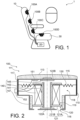
- FIG. 1 illustrates, in a schematic view, an aircraft chair, as a stimulation system 10, comprising four electromagnetic transducers 100A, 100B, 100C, 100D housed in a trim 30 of the aircraft chair, said chair being installed in an aircraft 1.
- the stimulation system 10 is an aircraft chair, the invention is of course not limited to this single application and concerns any type of stimulation system 10 intended to transmit vibratory stimuli and which is likely to include such electromagnetic transducers 100A, 100B, 100C, 100D.
- the stimulation system 10 can also be a land or marine motorized vehicle chair, an office chair or even a bed or a massage table, equipped with said electromagnetic transducers to provide, to the means of transmitting vibratory stimuli provided by the electromagnetic transducers, a massage or a sensitive signal to the user of said stimulation system, this without departing from the scope of the invention.
- transducers are aimed in particular at the admission of massage to users of said stimulation systems 10, other applications are perfectly conceivable, without departing from the scope of the invention.
- such transducers can be used in the context of user entertainment, such as video game activities or consumption of multimedia content, the transducers being able to apply infrasound or low frequency stimulation in connection with said activities.
- such transducers can be used to transmit information to the user of said stimulation system 10, such as, for example and in the context of an application to a pilot's chair aircraft, force feedback concerning piloting commands or flight information.
- Such a stimulation system 10 can be a wall or a floor, including in their lining 30 (that is to say their internal material of said wall or floor), an electromagnetic transducer 100A, 100B, 100C, 100D to transmit a vibration stimulus to the user when he comes into contact with a part of said wall or floor equipped by said electromagnetic transducer 100A, 100B, 100C, 100D.
- FIG 1 shows, in addition to the four electromagnetic transducers 100A, 100B, 100C, 100D which are integrated into the trim 30 of the chair, a control unit 20 of said transducers capable of supplying a control signal to said electromagnetic transducers 100A, 100B, 100C.
- a control unit 20 of said transducers capable of supplying a control signal to said electromagnetic transducers 100A, 100B, 100C.
- Such a configuration of the control unit 20 is of course only an example, other configurations are perfectly possible without departing from the scope of the invention, the control unit 20 being able for example to be integrated into a centralized control unit of a vehicle or even provided in two parts, a respective sub-unit integrated into each electromagnetic transducer 100A, 100B, 100C, 100D and a central unit connected to said control sub-unit.
- electromagnetic transducers 100A, 100B, 100C, 100D illustrated on the figure 1 is given as an example only and is in no way limiting.
- the chair includes a number of four electromagnetic transducers 100A, 100B, 100C, 100D with a distribution along the backrest and the seat, it is perfectly possible to distribute them differently.
- transducers electromagnetics 100A, 100B, 100C, 100D can be arranged in pairs distributed on either side of an axis of symmetry of the chair with a similar distribution along the backrest and the seat (that is to say a configuration with 8 electromagnetic transducers), or a large 100A, 100B, 100C, 100D electromagnetic transducer for the seat and 6 smaller 100A, 100B, 100C, 100D electromagnetic transducers for the backrest.
- the electromagnet 141 is secured to the movable element 120 and the first magnet 125 is secured to the housing 110.
- the housing 110 comprises a cover 115 having the support face 111 and a body 117 closed by said cover 115, the cover 115 being integral with the body 117.
- the body 117 has a main housing 118, delimited in part by the cover 115 and a secondary housing 119, opposite the cover 115.
- the main housing 118 and the secondary housing 119 each have a cylindrical shape of revolution and are in communication with one another at a common open base which is, for the main housing, opposite the cover 115.
- other shapes of body 117 are perfectly conceivable without departing from the scope of the invention.
- the body 117 and the cover 115 are made of a ferromagnetic material.
- the body may comprise openings 116, or vents, on a face opposite the cover.
- openings 116 allow fluid communication between the secondary housing 119 and the exterior of the body and thus allow the evacuation of part of the thermal energy generated by the electromagnet 141 during the operation of the electromagnetic transducer 100.
- the openings 116 can be chosen with a reduced size or with a metal mesh in order to provide electromagnetic shielding and thus avoid an emission outside the housing 110 of any electromagnetic disturbances that the electromagnetic actuation system 140 could generate.
- the body 117 and the cover 115 can both be made of electrically conductive materials.
- the movable element 120 comprises: - the electromagnet 141, comprising a coil of electrically conductive material, such as copper, and including the thermosensitive element 142, and - a core 121 made of ferromagnetic material of the electromagnet 141.
- the electromagnet 141 is referenced only by its coil, the core 121 being described independently of the rest of the electromagnet 141.
- the core 121 has the shape of a hollow cylinder of revolution with an open base which can also be defined as tubular, the bases of said cylinder having radial extensions so as to define along its side wall a housing for the coil of the electro -magnet 141.
- the core 121 can be presented in two parts, an outer cylinder 121A, having radial extensions and, an inner cylinder 121B inscribed inside the outer cylinder.
- the outer cylinders and interior 121A, 121B of the core are electrically isolated from each other by means, for example, of a layer of dielectric material disposed between them.
- the retention between the outer cylinder 121A and the inner cylinder 121B is achieved by crimping at the base of the inner cylinder 121B.
- Other holding systems, such as force mounting, are also possible without departing from the scope of the invention.
- the core 121 may comprise a winding of at least one sheet of ferrous material, two successive windings being separated from each other by a dielectric material.
- a winding can, for example, be formed by winding a single sheet of ferrous material coated with dielectric material such as a varnish.
- at least one of the outer cylinder 121A and the inner cylinder 121B can comprise such a winding.
- the movable element 120 only comprises the coil of the electromagnet 141 and the core 121
- the mobile element 120 comprises an insert made of non-magnetic material, this insert being inserted into the core in order to increase the mass of the mobile element 120.
- the mobile element, and therefore the electromagnet 141 is free of core 121.
- thermosensitive element 142 is, in the present embodiment, associated with the electromagnet 141 by being positioned between the coil of the electromagnet 141 and the core 121 or only in the coil to prevent excessive heating of the wire of the electromagnet coil. Such an association allows the thermosensitive element 142 to be subjected to temperature variations of the electromagnet 141. Of course, other arrangements/associations between the thermosensitive element 142 and the electromagnet 141 are possible. without departing from the scope of the invention. Thus, for example, in the case where the thermosensitive element 142 is a remote temperature sensor, such as an infrared temperature sensor, the thermosensitive element 142 can be arranged on the wall of the housing 110 facing the electromagnet 141 so as to allow measurement of the temperature of the electromagnet 141.
- the thermosensitive element 142 can be a temperature sensor connected to the control unit 20 and associated with a threshold temperature from which the control unit reduces, or even eliminates the power supply to the electromagnet 141 and thus reduce the thermal energy released by the latter.
- the control unit 20 is configured to recover the temperature signal supplied by the thermosensitive element and, when the signal supplied by the thermosensitive element corresponds to a temperature greater than or equal to, or even strictly greater than, the threshold temperature , limit, or even stop, the power supply to the electromagnet 141.
- the temperature sensor can be associated with two threshold temperatures, a first relatively low threshold temperature, for example, less than or equal to 50°C or even 60°C, from which the power supply to the electromagnet 141 is limited, and a second relatively high threshold temperature, for example greater than or equal to 80°C or even 100°C, from which the power supply to the electromagnet 141 is stopped, this only resuming from limited manner, when the temperature passes a third threshold temperature intermediate to said first and second threshold temperatures.
- a first relatively low threshold temperature for example, less than or equal to 50°C or even 60°C, from which the power supply to the electromagnet 141 is limited
- a second relatively high threshold temperature for example greater than or equal to 80°C or even 100°C
- thermosensitive element 142 can be a thermo-controlled switch, preferably self-resetting, such as a self-resetting thermal fuse also known by the English name "polyswitch fuse".
- thermosensitive element 142 is arranged in series with the electromagnet in such a way that the power supply to the electromagnet is stopped when the thermal fuse reaches a threshold temperature.
- the threshold temperature with which the thermosensitive element is associated is preferably less than or equal to 100°C, or even less than or equal to 70°C or even less than or equal to 60°C.
- said threshold temperature can be selected depending on the type of protection expected. Indeed, a temperature of 100°C is particularly suitable for protection of the electromagnet 141 and in particular of the dielectric material used for the winding of the coil of the electromagnet 141 while a temperature of 60°C is more suitable when we seek to preserve the comfort of the user as best as possible (a temperature of 100°C is nevertheless acceptable in particular due to the use of an interface element 113, as discussed below).
- the first magnet 145 can be arranged on one face of the cover 115, in the present embodiment , the support face 111, being integral with the latter, or on one of the faces of the housing 110 which is opposite the cover 115.
- the first magnet 145 is arranged on an external face of the cover 115, it is also possible, without departing from the scope of the invention, that the first magnet either arranged on an internal face of said cover as described below in the context of the second embodiment and illustrated on the Figure 3 .
- this face can be an external face as well as an internal face of said housing 110.
- the electromagnetic actuation system 140 may comprise, in addition to the first magnet 145, a second magnet 146 secured to one of a face of the cover 115 and the one of the faces of the housing 110 which is opposite the cover 115, as shown on the Figure 3 , the first magnet 145 being integral with another among one face of the cover 115 and one of the faces of the housing 110 which is opposite the cover 115.
- the mobile element 120 is housed partly in the main housing 118 and partly in the secondary housing 119.
- the secondary housing 119 can be equipped with guide elements 147, such as a sliding bearing, along which a part of the movable element 120, here a radial extension of the core 121 slides during the translational movement of the movable element 120.
- guide elements 147 such as a sliding bearing, along which a part of the movable element 120, here a radial extension of the core 121 slides during the translational movement of the movable element 120.
- Such sliding bearings can be provided by a polyamide, such as nylon, or by a polyoxymethylene, also known by the acronym POM.
- the movable element 120 is connected to the walls of the main housing 118 by means of the first elastic return element 130.
- the first elastic return element 130 comprises at least one thermal insulating material in order to limit the transmission of thermal energy from the element movable 120 (to be more precise from the electromagnet 141) towards the housing 110.
- This same insulating material is also preferentially non-magnetic, in order to avoid any interference with the electromagnetic actuation system 140 and more precisely not to short-circuit the magnetic flux of the core between electromagnet 141 and the first magnet 145 which produces the attraction-repulsion effect.
- the first elastic return element 130 may, for example, comprise a resin, such as a poly(methyl methacrylate) resin, alone or impregnating a fibrous support or fabric.
- a resin such as a poly(methyl methacrylate) resin
- the housing 110 may comprise at least one shock absorber 122A, 122B arranged to be interposed between the housing and the movable element during a possible extremal movement.
- the housing 110 may comprise a first and a second shock absorber 122A, 122B, the first shock absorber 122A on an internal face of the cover 115 facing the movable element 120, and the second shock absorber 122B, on an internal face of the body 117 at the opposite the internal face of the cover 115.
- the shock absorber 122A, 122B may comprise an elastomer, such as a silicone or a rubber (natural or synthetic).
- the mobile element 120, the first elastic return element 130 and the shock absorber(s) 122A, 122B can be configured so that the mobile element 120 has a resonance frequency of between 1 and 100 Hz, or even between 5 and 50 Hz and preferably between 10 and 30 Hz.
- the housing 110 may include, as illustrated in the figure 2 , at the level of the support face 111 the interface element 113 comprising at least one elastomer, said interface element 113 being intended to support, through a possible covering, the user for him transmit the movement of the mobile element 120.
- the interface element may comprise a plurality of cavities. Such cavities make it possible to give the interface element additional cushioning and thermal insulation compared to an interface element devoid of such cavities.
- the electromagnetic transducer may comprise a displacement sensor 143 arranged in the housing and configured to provide a signal relating to the movement of the box.
- the displacement sensor can thus be selected from the group comprising accelerometers, gyrometers and gyroscopes.
- the displacement sensor 151 can be, for example, arranged integral with the cover 115 or, according to a possibility not illustrated, integral with the body 117.
- the control unit 20 is able to determine information concerning the electromagnetic transducer 100 and the stimulation system 10, such as the orientation of the stimulation system 10, the installation of a new user on said stimulation system 10, an estimate of the body size of said user, and thus adapt the operating world of the or each electromagnetic transducer according to the determined information.
- This same information can also be used to adjust certain environmental parameters of the stimulation system. 10, such as the orientation of one or more lights, an air flow or equipment such as a screen.
- the displacement sensor 151 and the thermosensitive element 142 are both connected to a connector 152 passing through the housing 110 in order to allow connection to the control unit 20.
- This same connector 152 is also used to connect the electromagnet 141 to the control unit in order to authorize its power supply by the latter.
- FIG. 3 illustrates an electromagnetic transducer 100 according to a second embodiment in which cover 115 comprises at least one movable part 115A with respect to body 117, such that the movement of the movable element 120 drives said movable part 115A of the cover 115 on the go.
- An electromagnetic transducer 100 according to this second embodiment differs from an electromagnetic transducer 100 according to the first mode in that the cover 115 is movable with respect to the body 117 of the housing 110, in that the first magnet 145 is arranged on an internal face of the cover 115 housed in the shock absorber 122B and in that there is provided a second magnet 146 arranged on an internal face of the body 117 housed in the shock absorber 122A.
- the cover 115 is arranged to move in translation with respect to the body 117 of the housing 110, such that the movement of the movable element causes the cover 115 to move.
- the body can include, as illustrated in the Figure 3 , stops, able to delimit the amplitude of movement of the cover 115 with respect to the body 117.
- the cover 115 can be shaped in such a way as to have a resonance frequency of between 50 and 150 Hz, preferably between 75 and 125 Hz. In this way, by having a resonance frequency distinct from that of the mobile element 120, corresponding or not to a harmonic of the resonance frequency of the mobile element 120, the electromagnetic transducer 100 is able to provide a vibratory stimulus over a greater frequency range and thus facilitate relaxation for the user.
- FIG. 4 illustrates an electromagnetic transducer 100 according to a third embodiment in which cover 115 comprises a second elastic return element 115B connecting the movable part 115A of the cover 115 to the body 117.
- An electromagnetic transducer 100 according to a third embodiment differs from an electromagnetic transducer 100 according to the first embodiment in that it comprises the second elastic return element 115B and in that a movable part 115A of the cover moves screw -with respect to the body 117 by deformation of said second elastic return element 115B.
- the second elastic return element 115B and the movable part 115B can be provided in the form of two parts distinct from each other, one constituting the second elastic return element and the movable part forming the cover as as such.
- the second elastic element comprises a ferromagnetic material, such as for example a filler of ferrous material of a resin, in order to ensure magnetic continuity between the body 117 and the movable part 115B of the cover 115.
- the cover 115 can be formed in one piece having a variable thickness or a suitable shape with a central part, forming the movable part 115A, and a peripheral part 115B, shaped by its thickness or its shape, to form the second elastic return element, by which the cover 115 is connected to the body 111.
- the peripheral part 115B can have a relatively reduced thickness and/or a specific shape with respect to the movable part 115A . In this way, due to its relatively small thickness and/or its shape, the peripheral part has sufficient elasticity to form the second elastic return element 115B and the movable part 115A has, due to its relatively high thickness, sufficient rigidity to transmit a movement to the user.
Landscapes
- Engineering & Computer Science (AREA)
- Health & Medical Sciences (AREA)
- Aviation & Aerospace Engineering (AREA)
- Rehabilitation Therapy (AREA)
- Animal Behavior & Ethology (AREA)
- Epidemiology (AREA)
- Pain & Pain Management (AREA)
- Physical Education & Sports Medicine (AREA)
- Veterinary Medicine (AREA)
- Life Sciences & Earth Sciences (AREA)
- Public Health (AREA)
- General Health & Medical Sciences (AREA)
- Mechanical Engineering (AREA)
- Transportation (AREA)
- Percussion Or Vibration Massage (AREA)
- Apparatuses For Generation Of Mechanical Vibrations (AREA)
- Reciprocating, Oscillating Or Vibrating Motors (AREA)
Claims (10)
- Elektromechanischer Wandler (100, 100A, 100B, 100C, 100D) zum Übertragen eines Vibrationsreizes an einen Benutzer, wobei der elektromechanische Wandler (100, 100A, 100B, 100C, 100D) dazu bestimmt ist, in einem Verkleidungselement (30) eines Stimulationssystems (10) untergebracht zu werden, wobei eine Stützfläche (111) bündig mit dem Verkleidungselement (30) abschließt, um den Vibrationsreiz an den Benutzer des Stimulationssystems zu übertragen, wobei der elektromechanische Wandler (100, 100A, 100B, 100C, 100D) Folgendes umfasst:- ein Gehäuse (110), der die Stützfläche (111) aufweist;- ein bewegliches Element (120), das verschiebbar mittels mindestens eines ersten elastischen Rückstellelements (130) innerhalb des Gehäuses (110) montiert ist;- ein elektromagnetisches Betätigungssystem (140), das dazu konfiguriert ist, das bewegliche Element (120) in Bewegung zu setzen, wobei das Betätigungssystem (140) einen Elektromagnet (141) und mindestens einen ersten Magnet (145) umfasst, wobei der Elektromagnet (141) fest mit dem beweglichen Element (120) verbunden ist und der Magnet (145) fest mit dem Gehäuse (110) verbunden ist,wobei das erste elastische Rückstellelement (130) ein thermisch isolierendes Material umfasst, das eine Wärmeleitfähigkeit von weniger als 1 Wm-1K-1 aufweist, undder elektromechanische Wandler (100, 100A, 100B, 100C, 100D) ferner ein wärmeempfindliches Element (142) umfasst, das mit dem Elektromagnet (141) verbunden ist und aus wärmegesteuerten Schaltern und Temperatursensoren ausgewählt wird, wobei das wärmeempfindliche Element dazu ausgelegt ist, zu ermöglichen, dass die Stromversorgung des Elektromagnets begrenzt oder unterbrochen wird.
- Elektromechanischer Wandler (100, 100A, 100B, 100C, 100D) nach Anspruch 1, wobei das Gehäuse (110) eine Abdeckung (115) umfasst, das die Stützfläche (111) und einen durch die Abdeckung (115) verschlossenen Körper (117) aufweist, wobei das bewegliche Element (120) bezüglich des Körpers (117) verschiebbar montiert ist, wobei die Abdeckung (115) mindestens einen beweglichen Teil (115A) bezüglich des Körpers (117) umfasst.
- Elektromechanischer Wandler (100, 100A, 100B, 100C, 100D) nach Anspruch 2, wobei der bewegliche Teil (115A) der Abdeckung (115) mittels eines zweiten elastischen Rückstellelements (115B) mit dem Körper (117) verbunden ist, wobei die Anordnung aus dem beweglichen Teil (115B) der Abdeckung (115) und dem zweiten elastischen Rückstellelement (115B) eine Resonanzfrequenz aufweist, die größer ist als eine Resonanzfrequenz der Anordnung aus dem beweglichen Element (120) und dem ersten elastischen Rückstellelement (130).
- Elektromechanischer Wandler (100, 100A, 100B, 100C, 100D) nach einem der Ansprüche 1 bis 3, der ferner einen Verschiebungssensor (151) umfasst, der innerhalb des Gehäuses (110) angeordnet und dazu konfiguriert ist, ein Signal relativ zur Verschiebung des Gehäuses (110) bereitzustellen.
- Elektromechanischer Wandler (100, 100A, 100B, 100C, 100D) nach einem der Ansprüche 1 bis 4, wobei das bewegliche Element (120) einen Kern (121) des Elektromagnets (141) umfasst, wobei der Kern (121) mindestens eine Hohlform, beispielsweise eine Röhrenform, umfasst.
- Elektromechanischer Wandler (100, 100A, 100B, 100C, 100D) nach einem der Ansprüche 1 bis 5, wobei das Gehäuse (110) auf Höhe der Stützfläche (111) ein Schnittstellenelement (113) enthält, das mindestens ein Elastomer umfasst, wobei das Schnittstellenelement dazu bestimmt ist, durch eine mögliche Bekleidung des Stimulationssystems (10) am Benutzer anzuliegen, um den Vibrationsreiz an den Benutzer zu übertragen.
- Stimulationssystem (10), das dazu bestimmt ist, einem Benutzer Vibrationsreize bereitzustellen, und ein Verkleidungselement und mindestens einen elektromechanischen Wandler (100, 100A, 100B, 100C, 100D) nach einem der Ansprüche 1 bis 6 umfasst, wobei der mindestens eine elektromagnetische Wandler (100, 100A, 100B, 100C, 100D) in dem Verkleidungselement (30) untergebracht ist, wobei eine Stützfläche (111) bündig mit dem Verkleidungselement (30) abschließt.
- Stimulationssystem (10) nach Anspruch 7, wobei das wärmeempfindliche Element (142) des einen oder jedes elektromechanischen Wandlers (100, 100A, 100B, 100C, 100D) ein Temperatursensor ist und wobei das Stimulationssystem (10) ferner mindestens eine Steuereinheit (20) des oder der elektromechanischen Wandler (100A, 100B, 100C, 100D) umfasst, die dazu konfiguriert ist, den Elektromagnet (141) des oder der elektromechanischen Wandler (100A, 100B, 100C, 100D) mit Strom zu versorgen, wobei die Steuereinheit (20) ferner dazu konfiguriert ist, ein von dem oder den Temperatursensoren bereitgestelltes Temperatursignal abzurufen und, wenn ein oder mehrere von dem oder den Temperatursensoren bereitgestellte Temperatursignale einer Temperatur entsprechen, die größer oder gleich, oder sogar strikt größer als, eine Schwellentemperatur ist, um die Stromversorgung des oder der Elektromagneten (141) zu begrenzen oder sogar zu beenden, für die das oder die von dem oder den Temperatursensoren bereitgestellten Temperatursignale einer Temperatur entsprechen, die größer oder gleich der Schwellentemperatur ist.
- Stimulationssystem (10) nach Anspruch 8, wobei das Stimulationssystem (10) ein Fahrzeugsitz ist, wobei der Sitz vorzugsweise ein Sitz ist, der dazu bestimmt ist, ein Flugzeug auszustatten.
- Fahrzeug (1), das ein Stimulationssystem nach einem der Ansprüche 7 bis 9 umfasst.
Applications Claiming Priority (1)
| Application Number | Priority Date | Filing Date | Title |
|---|---|---|---|
| FR2105702A FR3123206B1 (fr) | 2021-05-31 | 2021-05-31 | Transducteur électromagnétique pour transmettre un stimulus vibratoire à un utilisateur et un système de stimulation comprenant un tel transducteur |
Publications (2)
| Publication Number | Publication Date |
|---|---|
| EP4098237A1 EP4098237A1 (de) | 2022-12-07 |
| EP4098237B1 true EP4098237B1 (de) | 2024-02-28 |
Family
ID=76807812
Family Applications (1)
| Application Number | Title | Priority Date | Filing Date |
|---|---|---|---|
| EP22171674.9A Active EP4098237B1 (de) | 2021-05-31 | 2022-05-04 | Elektromagnetischer transducer zum übertragen eines vibrationsreizes an einen benutzer und stimulationssystem mit einem solchen transducer |
Country Status (3)
| Country | Link |
|---|---|
| US (1) | US20220378651A1 (de) |
| EP (1) | EP4098237B1 (de) |
| FR (1) | FR3123206B1 (de) |
Families Citing this family (4)
| Publication number | Priority date | Publication date | Assignee | Title |
|---|---|---|---|---|
| US12465548B2 (en) * | 2021-07-01 | 2025-11-11 | Toyota Motor Engineering & Manufacturing North America, Inc. | Artificial muscle light weight seat massager and haptic response chair |
| US20240033174A1 (en) * | 2022-07-28 | 2024-02-01 | Samsung Electronics Co., Ltd. | Massage apparatus |
| KR20250137642A (ko) | 2023-01-20 | 2025-09-18 | 레겟 앤드 플랫 캐나다 코포레이션 | 익사이터 기반 시트 마사지 시스템에서 코일 압축의 감소 |
| EP4473952A1 (de) * | 2023-06-08 | 2024-12-11 | Jean-Philippe Thome | Vorrichtung zur verhinderung von dekubitus, möbelträgerelement mit einer solchen vorrichtung und verfahren zum bestücken eines trägerelements mit einer solchen vorrichtung |
Family Cites Families (17)
| Publication number | Priority date | Publication date | Assignee | Title |
|---|---|---|---|---|
| US4354067A (en) | 1978-05-17 | 1982-10-12 | Bodysonic Kabushiki Kaisha | Audio-band electromechanical vibration converter |
| FR2627693B1 (fr) * | 1988-02-26 | 1991-06-28 | Romain Michel | Appareil electromagnetique pour traitements medicaux par stimulations vibratoires locales |
| KR920002929Y1 (ko) * | 1990-02-17 | 1992-05-08 | 이정기 | 스피커 |
| JP3382061B2 (ja) * | 1995-05-31 | 2003-03-04 | 松下電工株式会社 | リニア振動モータ |
| US6487300B1 (en) * | 1999-12-17 | 2002-11-26 | Samsung Electro-Mechanics Co., Ltd. | Vibration speaker |
| US7755227B2 (en) * | 2005-10-19 | 2010-07-13 | Alps Electric Co., Ltd. | Vibration generator |
| JP5313822B2 (ja) * | 2009-09-18 | 2013-10-09 | パナソニック株式会社 | マッサージ機 |
| EP2355544A1 (de) * | 2009-12-21 | 2011-08-10 | Nxp B.V. | Aufhängungsglied für einen Schwingungsaktuator |
| US20170042760A1 (en) * | 2014-04-16 | 2017-02-16 | Christopher Chad Hamilton | Stimulating devices |
| CN110012674A (zh) * | 2016-08-05 | 2019-07-12 | 萨巴帕克公司 | 提供触感的换能器系统 |
| WO2019044824A1 (ja) * | 2017-08-31 | 2019-03-07 | パイオニア株式会社 | 座席 |
| US12023299B2 (en) * | 2017-11-27 | 2024-07-02 | Jaguar Precision Industry Co., Ltd. | Massage device |
| CN108670782A (zh) * | 2018-05-04 | 2018-10-19 | 郑州飞龙医疗设备有限公司 | 一种脉冲智能治疗枪 |
| KR102131846B1 (ko) * | 2018-11-16 | 2020-07-09 | 부전전자 주식회사 | 선형 진동발생장치 |
| KR20210047576A (ko) * | 2019-10-22 | 2021-04-30 | 주식회사 씨케이머티리얼즈랩 | 래디얼 마그넷 액추에이터 |
| US11354986B2 (en) * | 2020-01-28 | 2022-06-07 | GM Global Technology Operations LLC | Haptic device with vibration motor and seat assembly |
| FR3121883B1 (fr) * | 2021-04-19 | 2024-08-30 | Faurecia Sieges Dautomobile | Siège de véhicule |
-
2021
- 2021-05-31 FR FR2105702A patent/FR3123206B1/fr active Active
-
2022
- 2022-05-04 EP EP22171674.9A patent/EP4098237B1/de active Active
- 2022-05-27 US US17/804,401 patent/US20220378651A1/en not_active Abandoned
Also Published As
| Publication number | Publication date |
|---|---|
| US20220378651A1 (en) | 2022-12-01 |
| FR3123206B1 (fr) | 2025-01-10 |
| FR3123206A1 (fr) | 2022-12-02 |
| EP4098237A1 (de) | 2022-12-07 |
Similar Documents
| Publication | Publication Date | Title |
|---|---|---|
| EP4098237B1 (de) | Elektromagnetischer transducer zum übertragen eines vibrationsreizes an einen benutzer und stimulationssystem mit einem solchen transducer | |
| EP0440536B1 (de) | Verbesserungen zu hydraulischen schwingungsverhindernden Vorrichtungen | |
| FR2579283A1 (fr) | Amortisseur de vibrations electromagnetique | |
| FR2694354A1 (fr) | Support élastique à remplissage de fluide comportant une chambre de réception de vide et une chambre d'air auxiliaire pour permettre les variations de volume d'une chambre d'équilibre. | |
| US20150117668A1 (en) | Airplane seat, audio system, and airplane | |
| WO2011095928A1 (fr) | Electrovanne pilote | |
| WO2014091090A1 (fr) | Actionneur pour module d'interface tactile à retour haptique | |
| EP0893636B1 (de) | Magnetventilanordnung mit elastischem Mittel zur Befestigung auf seinem Stützblock, wie Hydraulikblock | |
| FR3102724A1 (fr) | Dispositif de vibration intégré à un siège | |
| FR2965683A1 (fr) | Installation electromagnetique et installation d'assistance de conduite equipee d'une telle installation | |
| EP0893620A1 (de) | Elektromagnetischer Betätiger und hydraulisches Antischwingungslager mit einem solchen Betätiger | |
| EP4179736B1 (de) | Elektrodynamischer wandler für fahrzeug | |
| EP3276200B1 (de) | Hydraulische schwingungsdämpfende vorrichtung | |
| FR3054628A1 (fr) | Dispositif antivibratoire hydraulique | |
| FR3029251A1 (fr) | Support antivibratoire hydraulique pilotable | |
| FR2684428A1 (fr) | Fixation elastique ayant une chambre de reception de pression en communication avec une chambre de fluide auxiliaire partiellement definie par une plaque oscillante actionnee par une bobine mobile dans un entrefer annulaire. | |
| EP1623107B1 (de) | Fluideinspritzvorrichtung | |
| EP2244168A2 (de) | Steuervorrichtung mit haptischer Rückkopplung und entsprechendes Stellglied | |
| EP3453103B1 (de) | Geräuschreduzierendes bauteil auf dem gehäuse eines elektromotors | |
| KR101806630B1 (ko) | 음향 가진 장치 | |
| EP0852060B1 (de) | Elektromagnetischer linearbetätiger mit bewegbaren platten und regler für flüssigkeiten mit ventilen gesteuert durch einen solchen betätiger | |
| FR3054619A1 (fr) | Servocommande a stabilisation integree au distributeur pour les commandes de vol d'un aeronef | |
| EP0419352A1 (de) | Elektromagnetventil mit Dauermagnet | |
| WO2010046494A1 (fr) | Dispositif de commande à retour haptique | |
| FR2853610A1 (fr) | Servomoteur d'assistance pneumatique au freinage a bruit de fonctionnement reduit |
Legal Events
| Date | Code | Title | Description |
|---|---|---|---|
| PUAI | Public reference made under article 153(3) epc to a published international application that has entered the european phase |
Free format text: ORIGINAL CODE: 0009012 |
|
| STAA | Information on the status of an ep patent application or granted ep patent |
Free format text: STATUS: THE APPLICATION HAS BEEN PUBLISHED |
|
| AK | Designated contracting states |
Kind code of ref document: A1 Designated state(s): AL AT BE BG CH CY CZ DE DK EE ES FI FR GB GR HR HU IE IS IT LI LT LU LV MC MK MT NL NO PL PT RO RS SE SI SK SM TR |
|
| STAA | Information on the status of an ep patent application or granted ep patent |
Free format text: STATUS: REQUEST FOR EXAMINATION WAS MADE |
|
| 17P | Request for examination filed |
Effective date: 20230509 |
|
| RBV | Designated contracting states (corrected) |
Designated state(s): AL AT BE BG CH CY CZ DE DK EE ES FI FR GB GR HR HU IE IS IT LI LT LU LV MC MK MT NL NO PL PT RO RS SE SI SK SM TR |
|
| GRAP | Despatch of communication of intention to grant a patent |
Free format text: ORIGINAL CODE: EPIDOSNIGR1 |
|
| STAA | Information on the status of an ep patent application or granted ep patent |
Free format text: STATUS: GRANT OF PATENT IS INTENDED |
|
| INTG | Intention to grant announced |
Effective date: 20230929 |
|
| GRAS | Grant fee paid |
Free format text: ORIGINAL CODE: EPIDOSNIGR3 |
|
| GRAA | (expected) grant |
Free format text: ORIGINAL CODE: 0009210 |
|
| STAA | Information on the status of an ep patent application or granted ep patent |
Free format text: STATUS: THE PATENT HAS BEEN GRANTED |
|
| AK | Designated contracting states |
Kind code of ref document: B1 Designated state(s): AL AT BE BG CH CY CZ DE DK EE ES FI FR GB GR HR HU IE IS IT LI LT LU LV MC MK MT NL NO PL PT RO RS SE SI SK SM TR |
|
| REG | Reference to a national code |
Ref country code: GB Ref legal event code: FG4D Free format text: NOT ENGLISH |
|
| REG | Reference to a national code |
Ref country code: CH Ref legal event code: EP |
|
| REG | Reference to a national code |
Ref country code: DE Ref legal event code: R096 Ref document number: 602022002108 Country of ref document: DE |
|
| REG | Reference to a national code |
Ref country code: IE Ref legal event code: FG4D Free format text: LANGUAGE OF EP DOCUMENT: FRENCH |
|
| REG | Reference to a national code |
Ref country code: LT Ref legal event code: MG9D |
|
| PG25 | Lapsed in a contracting state [announced via postgrant information from national office to epo] |
Ref country code: IS Free format text: LAPSE BECAUSE OF FAILURE TO SUBMIT A TRANSLATION OF THE DESCRIPTION OR TO PAY THE FEE WITHIN THE PRESCRIBED TIME-LIMIT Effective date: 20240628 |
|
| REG | Reference to a national code |
Ref country code: NL Ref legal event code: MP Effective date: 20240228 |
|
| PG25 | Lapsed in a contracting state [announced via postgrant information from national office to epo] |
Ref country code: LT Free format text: LAPSE BECAUSE OF FAILURE TO SUBMIT A TRANSLATION OF THE DESCRIPTION OR TO PAY THE FEE WITHIN THE PRESCRIBED TIME-LIMIT Effective date: 20240228 |
|
| PG25 | Lapsed in a contracting state [announced via postgrant information from national office to epo] |
Ref country code: GR Free format text: LAPSE BECAUSE OF FAILURE TO SUBMIT A TRANSLATION OF THE DESCRIPTION OR TO PAY THE FEE WITHIN THE PRESCRIBED TIME-LIMIT Effective date: 20240529 |
|
| PG25 | Lapsed in a contracting state [announced via postgrant information from national office to epo] |
Ref country code: HR Free format text: LAPSE BECAUSE OF FAILURE TO SUBMIT A TRANSLATION OF THE DESCRIPTION OR TO PAY THE FEE WITHIN THE PRESCRIBED TIME-LIMIT Effective date: 20240228 Ref country code: RS Free format text: LAPSE BECAUSE OF FAILURE TO SUBMIT A TRANSLATION OF THE DESCRIPTION OR TO PAY THE FEE WITHIN THE PRESCRIBED TIME-LIMIT Effective date: 20240528 Ref country code: NL Free format text: LAPSE BECAUSE OF FAILURE TO SUBMIT A TRANSLATION OF THE DESCRIPTION OR TO PAY THE FEE WITHIN THE PRESCRIBED TIME-LIMIT Effective date: 20240228 |
|
| PG25 | Lapsed in a contracting state [announced via postgrant information from national office to epo] |
Ref country code: ES Free format text: LAPSE BECAUSE OF FAILURE TO SUBMIT A TRANSLATION OF THE DESCRIPTION OR TO PAY THE FEE WITHIN THE PRESCRIBED TIME-LIMIT Effective date: 20240228 |
|
| PG25 | Lapsed in a contracting state [announced via postgrant information from national office to epo] |
Ref country code: RS Free format text: LAPSE BECAUSE OF FAILURE TO SUBMIT A TRANSLATION OF THE DESCRIPTION OR TO PAY THE FEE WITHIN THE PRESCRIBED TIME-LIMIT Effective date: 20240528 Ref country code: NO Free format text: LAPSE BECAUSE OF FAILURE TO SUBMIT A TRANSLATION OF THE DESCRIPTION OR TO PAY THE FEE WITHIN THE PRESCRIBED TIME-LIMIT Effective date: 20240528 Ref country code: NL Free format text: LAPSE BECAUSE OF FAILURE TO SUBMIT A TRANSLATION OF THE DESCRIPTION OR TO PAY THE FEE WITHIN THE PRESCRIBED TIME-LIMIT Effective date: 20240228 Ref country code: LT Free format text: LAPSE BECAUSE OF FAILURE TO SUBMIT A TRANSLATION OF THE DESCRIPTION OR TO PAY THE FEE WITHIN THE PRESCRIBED TIME-LIMIT Effective date: 20240228 Ref country code: IS Free format text: LAPSE BECAUSE OF FAILURE TO SUBMIT A TRANSLATION OF THE DESCRIPTION OR TO PAY THE FEE WITHIN THE PRESCRIBED TIME-LIMIT Effective date: 20240628 Ref country code: HR Free format text: LAPSE BECAUSE OF FAILURE TO SUBMIT A TRANSLATION OF THE DESCRIPTION OR TO PAY THE FEE WITHIN THE PRESCRIBED TIME-LIMIT Effective date: 20240228 Ref country code: GR Free format text: LAPSE BECAUSE OF FAILURE TO SUBMIT A TRANSLATION OF THE DESCRIPTION OR TO PAY THE FEE WITHIN THE PRESCRIBED TIME-LIMIT Effective date: 20240529 Ref country code: FI Free format text: LAPSE BECAUSE OF FAILURE TO SUBMIT A TRANSLATION OF THE DESCRIPTION OR TO PAY THE FEE WITHIN THE PRESCRIBED TIME-LIMIT Effective date: 20240228 Ref country code: ES Free format text: LAPSE BECAUSE OF FAILURE TO SUBMIT A TRANSLATION OF THE DESCRIPTION OR TO PAY THE FEE WITHIN THE PRESCRIBED TIME-LIMIT Effective date: 20240228 Ref country code: BG Free format text: LAPSE BECAUSE OF FAILURE TO SUBMIT A TRANSLATION OF THE DESCRIPTION OR TO PAY THE FEE WITHIN THE PRESCRIBED TIME-LIMIT Effective date: 20240228 |
|
| PG25 | Lapsed in a contracting state [announced via postgrant information from national office to epo] |
Ref country code: PL Free format text: LAPSE BECAUSE OF FAILURE TO SUBMIT A TRANSLATION OF THE DESCRIPTION OR TO PAY THE FEE WITHIN THE PRESCRIBED TIME-LIMIT Effective date: 20240228 Ref country code: PT Free format text: LAPSE BECAUSE OF FAILURE TO SUBMIT A TRANSLATION OF THE DESCRIPTION OR TO PAY THE FEE WITHIN THE PRESCRIBED TIME-LIMIT Effective date: 20240628 |
|
| REG | Reference to a national code |
Ref country code: AT Ref legal event code: MK05 Ref document number: 1660569 Country of ref document: AT Kind code of ref document: T Effective date: 20240228 |
|
| PG25 | Lapsed in a contracting state [announced via postgrant information from national office to epo] |
Ref country code: SE Free format text: LAPSE BECAUSE OF FAILURE TO SUBMIT A TRANSLATION OF THE DESCRIPTION OR TO PAY THE FEE WITHIN THE PRESCRIBED TIME-LIMIT Effective date: 20240228 Ref country code: PT Free format text: LAPSE BECAUSE OF FAILURE TO SUBMIT A TRANSLATION OF THE DESCRIPTION OR TO PAY THE FEE WITHIN THE PRESCRIBED TIME-LIMIT Effective date: 20240628 Ref country code: PL Free format text: LAPSE BECAUSE OF FAILURE TO SUBMIT A TRANSLATION OF THE DESCRIPTION OR TO PAY THE FEE WITHIN THE PRESCRIBED TIME-LIMIT Effective date: 20240228 Ref country code: LV Free format text: LAPSE BECAUSE OF FAILURE TO SUBMIT A TRANSLATION OF THE DESCRIPTION OR TO PAY THE FEE WITHIN THE PRESCRIBED TIME-LIMIT Effective date: 20240228 |
|
| PG25 | Lapsed in a contracting state [announced via postgrant information from national office to epo] |
Ref country code: DK Free format text: LAPSE BECAUSE OF FAILURE TO SUBMIT A TRANSLATION OF THE DESCRIPTION OR TO PAY THE FEE WITHIN THE PRESCRIBED TIME-LIMIT Effective date: 20240228 |
|
| PG25 | Lapsed in a contracting state [announced via postgrant information from national office to epo] |
Ref country code: SM Free format text: LAPSE BECAUSE OF FAILURE TO SUBMIT A TRANSLATION OF THE DESCRIPTION OR TO PAY THE FEE WITHIN THE PRESCRIBED TIME-LIMIT Effective date: 20240228 |
|
| PG25 | Lapsed in a contracting state [announced via postgrant information from national office to epo] |
Ref country code: EE Free format text: LAPSE BECAUSE OF FAILURE TO SUBMIT A TRANSLATION OF THE DESCRIPTION OR TO PAY THE FEE WITHIN THE PRESCRIBED TIME-LIMIT Effective date: 20240228 Ref country code: CZ Free format text: LAPSE BECAUSE OF FAILURE TO SUBMIT A TRANSLATION OF THE DESCRIPTION OR TO PAY THE FEE WITHIN THE PRESCRIBED TIME-LIMIT Effective date: 20240228 |
|
| PG25 | Lapsed in a contracting state [announced via postgrant information from national office to epo] |
Ref country code: AT Free format text: LAPSE BECAUSE OF FAILURE TO SUBMIT A TRANSLATION OF THE DESCRIPTION OR TO PAY THE FEE WITHIN THE PRESCRIBED TIME-LIMIT Effective date: 20240228 |
|
| PG25 | Lapsed in a contracting state [announced via postgrant information from national office to epo] |
Ref country code: SK Free format text: LAPSE BECAUSE OF FAILURE TO SUBMIT A TRANSLATION OF THE DESCRIPTION OR TO PAY THE FEE WITHIN THE PRESCRIBED TIME-LIMIT Effective date: 20240228 |
|
| PG25 | Lapsed in a contracting state [announced via postgrant information from national office to epo] |
Ref country code: SM Free format text: LAPSE BECAUSE OF FAILURE TO SUBMIT A TRANSLATION OF THE DESCRIPTION OR TO PAY THE FEE WITHIN THE PRESCRIBED TIME-LIMIT Effective date: 20240228 Ref country code: SK Free format text: LAPSE BECAUSE OF FAILURE TO SUBMIT A TRANSLATION OF THE DESCRIPTION OR TO PAY THE FEE WITHIN THE PRESCRIBED TIME-LIMIT Effective date: 20240228 Ref country code: RO Free format text: LAPSE BECAUSE OF FAILURE TO SUBMIT A TRANSLATION OF THE DESCRIPTION OR TO PAY THE FEE WITHIN THE PRESCRIBED TIME-LIMIT Effective date: 20240228 Ref country code: EE Free format text: LAPSE BECAUSE OF FAILURE TO SUBMIT A TRANSLATION OF THE DESCRIPTION OR TO PAY THE FEE WITHIN THE PRESCRIBED TIME-LIMIT Effective date: 20240228 Ref country code: DK Free format text: LAPSE BECAUSE OF FAILURE TO SUBMIT A TRANSLATION OF THE DESCRIPTION OR TO PAY THE FEE WITHIN THE PRESCRIBED TIME-LIMIT Effective date: 20240228 Ref country code: CZ Free format text: LAPSE BECAUSE OF FAILURE TO SUBMIT A TRANSLATION OF THE DESCRIPTION OR TO PAY THE FEE WITHIN THE PRESCRIBED TIME-LIMIT Effective date: 20240228 Ref country code: AT Free format text: LAPSE BECAUSE OF FAILURE TO SUBMIT A TRANSLATION OF THE DESCRIPTION OR TO PAY THE FEE WITHIN THE PRESCRIBED TIME-LIMIT Effective date: 20240228 |
|
| REG | Reference to a national code |
Ref country code: DE Ref legal event code: R097 Ref document number: 602022002108 Country of ref document: DE |
|
| REG | Reference to a national code |
Ref country code: DE Ref legal event code: R119 Ref document number: 602022002108 Country of ref document: DE |
|
| PG25 | Lapsed in a contracting state [announced via postgrant information from national office to epo] |
Ref country code: IT Free format text: LAPSE BECAUSE OF FAILURE TO SUBMIT A TRANSLATION OF THE DESCRIPTION OR TO PAY THE FEE WITHIN THE PRESCRIBED TIME-LIMIT Effective date: 20240228 |
|
| PG25 | Lapsed in a contracting state [announced via postgrant information from national office to epo] |
Ref country code: IT Free format text: LAPSE BECAUSE OF FAILURE TO SUBMIT A TRANSLATION OF THE DESCRIPTION OR TO PAY THE FEE WITHIN THE PRESCRIBED TIME-LIMIT Effective date: 20240228 |
|
| PLBE | No opposition filed within time limit |
Free format text: ORIGINAL CODE: 0009261 |
|
| STAA | Information on the status of an ep patent application or granted ep patent |
Free format text: STATUS: NO OPPOSITION FILED WITHIN TIME LIMIT |
|
| PG25 | Lapsed in a contracting state [announced via postgrant information from national office to epo] |
Ref country code: MC Free format text: LAPSE BECAUSE OF FAILURE TO SUBMIT A TRANSLATION OF THE DESCRIPTION OR TO PAY THE FEE WITHIN THE PRESCRIBED TIME-LIMIT Effective date: 20240228 |
|
| PG25 | Lapsed in a contracting state [announced via postgrant information from national office to epo] |
Ref country code: LU Free format text: LAPSE BECAUSE OF NON-PAYMENT OF DUE FEES Effective date: 20240504 |
|
| PG25 | Lapsed in a contracting state [announced via postgrant information from national office to epo] |
Ref country code: MC Free format text: LAPSE BECAUSE OF FAILURE TO SUBMIT A TRANSLATION OF THE DESCRIPTION OR TO PAY THE FEE WITHIN THE PRESCRIBED TIME-LIMIT Effective date: 20240228 Ref country code: LU Free format text: LAPSE BECAUSE OF NON-PAYMENT OF DUE FEES Effective date: 20240504 |
|
| 26N | No opposition filed |
Effective date: 20241129 |
|
| REG | Reference to a national code |
Ref country code: BE Ref legal event code: MM Effective date: 20240531 |
|
| PG25 | Lapsed in a contracting state [announced via postgrant information from national office to epo] |
Ref country code: DE Free format text: LAPSE BECAUSE OF NON-PAYMENT OF DUE FEES Effective date: 20241203 |
|
| PG25 | Lapsed in a contracting state [announced via postgrant information from national office to epo] |
Ref country code: IE Free format text: LAPSE BECAUSE OF NON-PAYMENT OF DUE FEES Effective date: 20240504 |
|
| PG25 | Lapsed in a contracting state [announced via postgrant information from national office to epo] |
Ref country code: SI Free format text: LAPSE BECAUSE OF FAILURE TO SUBMIT A TRANSLATION OF THE DESCRIPTION OR TO PAY THE FEE WITHIN THE PRESCRIBED TIME-LIMIT Effective date: 20240228 Ref country code: BE Free format text: LAPSE BECAUSE OF NON-PAYMENT OF DUE FEES Effective date: 20240531 |
|
| PGFP | Annual fee paid to national office [announced via postgrant information from national office to epo] |
Ref country code: FR Payment date: 20250530 Year of fee payment: 4 |
|
| PG25 | Lapsed in a contracting state [announced via postgrant information from national office to epo] |
Ref country code: CY Free format text: LAPSE BECAUSE OF FAILURE TO SUBMIT A TRANSLATION OF THE DESCRIPTION OR TO PAY THE FEE WITHIN THE PRESCRIBED TIME-LIMIT; INVALID AB INITIO Effective date: 20220504 |
|
| PG25 | Lapsed in a contracting state [announced via postgrant information from national office to epo] |
Ref country code: HU Free format text: LAPSE BECAUSE OF FAILURE TO SUBMIT A TRANSLATION OF THE DESCRIPTION OR TO PAY THE FEE WITHIN THE PRESCRIBED TIME-LIMIT; INVALID AB INITIO Effective date: 20220504 |
|
| REG | Reference to a national code |
Ref country code: CH Ref legal event code: H13 Free format text: ST27 STATUS EVENT CODE: U-0-0-H10-H13 (AS PROVIDED BY THE NATIONAL OFFICE) Effective date: 20251223 |
|
| PG25 | Lapsed in a contracting state [announced via postgrant information from national office to epo] |
Ref country code: CH Free format text: LAPSE BECAUSE OF NON-PAYMENT OF DUE FEES Effective date: 20250531 |