EP4098148B1 - Vorrichtung zum auftragen eines flüssigen oder pastenartigen produkts auf keratinfasern - Google Patents
Vorrichtung zum auftragen eines flüssigen oder pastenartigen produkts auf keratinfasern Download PDFInfo
- Publication number
- EP4098148B1 EP4098148B1 EP22186792.2A EP22186792A EP4098148B1 EP 4098148 B1 EP4098148 B1 EP 4098148B1 EP 22186792 A EP22186792 A EP 22186792A EP 4098148 B1 EP4098148 B1 EP 4098148B1
- Authority
- EP
- European Patent Office
- Prior art keywords
- spikes
- region
- reference plane
- figures
- plane
- Prior art date
- Legal status (The legal status is an assumption and is not a legal conclusion. Google has not performed a legal analysis and makes no representation as to the accuracy of the status listed.)
- Active
Links
Images
Classifications
-
- A—HUMAN NECESSITIES
- A45—HAND OR TRAVELLING ARTICLES
- A45D—HAIRDRESSING OR SHAVING EQUIPMENT; EQUIPMENT FOR COSMETICS OR COSMETIC TREATMENTS, e.g. FOR MANICURING OR PEDICURING
- A45D40/00—Casings or accessories specially adapted for storing or handling solid or pasty toiletry or cosmetic substances, e.g. shaving soaps or lipsticks
- A45D40/26—Appliances specially adapted for applying pasty paint, e.g. using roller, using a ball
- A45D40/262—Appliances specially adapted for applying pasty paint, e.g. using roller, using a ball using a brush or the like
- A45D40/264—Appliances specially adapted for applying pasty paint, e.g. using roller, using a ball using a brush or the like movable within the container
-
- A—HUMAN NECESSITIES
- A45—HAND OR TRAVELLING ARTICLES
- A45D—HAIRDRESSING OR SHAVING EQUIPMENT; EQUIPMENT FOR COSMETICS OR COSMETIC TREATMENTS, e.g. FOR MANICURING OR PEDICURING
- A45D40/00—Casings or accessories specially adapted for storing or handling solid or pasty toiletry or cosmetic substances, e.g. shaving soaps or lipsticks
- A45D40/26—Appliances specially adapted for applying pasty paint, e.g. using roller, using a ball
- A45D40/262—Appliances specially adapted for applying pasty paint, e.g. using roller, using a ball using a brush or the like
-
- A—HUMAN NECESSITIES
- A46—BRUSHWARE
- A46B—BRUSHES
- A46B1/00—Brush bodies and bristles moulded as a unit
-
- A—HUMAN NECESSITIES
- A46—BRUSHWARE
- A46B—BRUSHES
- A46B9/00—Arrangements of the bristles in the brush body
- A46B9/02—Position or arrangement of bristles in relation to surface of the brush body, e.g. inclined, in rows, in groups
- A46B9/021—Position or arrangement of bristles in relation to surface of the brush body, e.g. inclined, in rows, in groups arranged like in cosmetics brushes, e.g. mascara, nail polish, eye shadow
-
- A—HUMAN NECESSITIES
- A46—BRUSHWARE
- A46B—BRUSHES
- A46B9/00—Arrangements of the bristles in the brush body
- A46B9/02—Position or arrangement of bristles in relation to surface of the brush body, e.g. inclined, in rows, in groups
- A46B9/028—Bristle profile, the end of the bristle defining a surface other than a single plane or deviating from a simple geometric form, e.g. cylinder, sphere or cone
-
- A—HUMAN NECESSITIES
- A46—BRUSHWARE
- A46D—MANUFACTURE OF BRUSHES
- A46D1/00—Bristles; Selection of materials for bristles
-
- A—HUMAN NECESSITIES
- A46—BRUSHWARE
- A46D—MANUFACTURE OF BRUSHES
- A46D1/00—Bristles; Selection of materials for bristles
- A46D1/02—Bristles details
- A46D1/0238—Bristles with non-round cross-section
-
- A—HUMAN NECESSITIES
- A46—BRUSHWARE
- A46D—MANUFACTURE OF BRUSHES
- A46D1/00—Bristles; Selection of materials for bristles
- A46D1/02—Bristles details
- A46D1/0253—Bristles having a shape which is not a straight line, e.g. curved, "S", hook, loop
-
- A—HUMAN NECESSITIES
- A46—BRUSHWARE
- A46D—MANUFACTURE OF BRUSHES
- A46D1/00—Bristles; Selection of materials for bristles
- A46D1/02—Bristles details
- A46D1/0292—Bristles having split ends
Definitions
- the application device itself may be, for example, an elongated brush with a central core from which a set of bristles or spikes protrude.
- the bristles are based on old technology: a twisted metal wire holds the bristles, which are protruded transversely.
- An example of an application is illustrated in the US patent US 5,611,361 .
- the application device is in the form of a brush comprising a series of spikes embedded on the longitudinal core of the brush.
- the assembly is molded from plastic.
- An application device thus forms, with a suitable reservoir into which it can be inserted, a cosmetic product dispenser.
- Applications FR 2 810 860 And WO 2011/045770 show some examples of applicators based on this concept.
- An example of an applicator according to the preamble of the claim is known from EP1767119A1 .
- the disadvantages of the application devices, or brushes, of the prior art are that the spikes do not allow the cosmetic product to be correctly transferred from the reservoir to the spikes, and the product to be properly applied to the keratin fibres, to lengthen, thicken and/or separate them.
- Brushes of this type are not as effective as they used to be because the flat sides do not help separate the lashes and the non-flat sides do not help with mascara loading. With this type of brush, the user is therefore forced to make several strokes over their lashes while reversing the movement of the brush to ensure they collect enough mascara.
- FR 2 930 875 which describes a cosmetic product applicator device comprising a longitudinal core supporting several rows of spikes having a flat face and projecting radially from the core.
- the spikes are distributed in at least one row parallel to the longitudinal axis of the core, such that in the same row the spikes are positioned alternately on either side of a central line (or plane) of the row, with their flat face facing the inside of the row.
- the flat faces of the spikes in the same row extend perpendicular to the core and are aligned, and they are oriented in both rotating directions around the core.
- each spike must contribute to improving, alone or in combination with other spikes, both the product load and the separation of the eyelashes or keratin fibers.
- the invention aims to remedy the drawbacks of the state of the art, particularly with regard to the loading of cosmetic product and the separation of eyelashes.
- the invention proposes a device for applying a fluid or pasty type product to keratin fibers, comprising a central core of elongated shape which extends along a longitudinal axis XX, at least one row of elongated spikes comprising a first end embedded on the core and a second free end, the spikes and the core being formed in a single piece.
- At least one of the spikes is delimited by a first flat face coinciding with a longitudinal plane of the device, called the reference plane P, which extends radially with respect to the core, and by a second flat face forming with said first flat face an angle of approximately 180°; furthermore, said at least one spike comprises a first zone embedded on the core and of substantially constant cross-section, the second zone comprising at least a first juxtaposed portion and in the extension of the first zone, and a second juxtaposed portion overlapping with the first portion along said reference plane P.
- the shape and/or arrangement of two pins successively implanted along the axis XX is capable of creating at least one distal opening between them.
- Said distal opening can be open towards the free end of the pin, in the general shape of a tuning fork.
- the shape and/or arrangement of two pins successively implanted along the XX axis is capable of creating a second opening between them.
- the distal opening and the second opening can be separate or communicating.
- At least two of the pins constituting a row have an identical orientation.
- At least two of the pins constituting a row have a different orientation.
- the distance measured along the XX axis between two successive pins can be negative, zero or positive, less than approximately 2 mm. This distance is easily adapted to the particular case considered.
- the first and second faces form an angle of approximately 180° between them
- the second zone comprises at least a first portion juxtaposed and in the extension of the first zone, and a second portion juxtaposed and overlapping with the first portion according to said reference plane P.
- said first portion comprises a first bulge; the second portion comprises a second bulge oriented differently from said first bulge.
- said second portion of the second zone has a U shape which extends substantially parallel to said reference plane, on the other side of said reference plane P relative to the first portion.
- the second zone of the spike(s) may extend according to a succession of concave and convex curvatures.
- At least one of the spikes comprises at least one protrusion resulting from a bulge and/or a convexity.
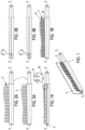
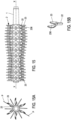
- FIG. 1 shows the principle of the invention which therefore relates to a device for applying a fluid or pasty type product to keratin fibers such as eyelashes.
- this device comprises an elongated core 1 which extends along a longitudinal axis XX; the cross-section of the core may or may not be constant.
- At least one row of pins or protuberances 2, of generally elongated shape, comprise a first end 20 embedded on the core 1 and a second free end 21; the pins 2 and the core are advantageously formed in a single piece, in particular from plastic from a mold.
- the application device is of generally elongated shape and its external volume may take different forms: cylindrical, truncated cone, peanut-shaped or other; the professional chooses it according to the specific case.
- Figures 1A and 1B show a substantially cylindrical exterior volume; the Figure 2A a peanut-shaped exterior; Figure 3A a wavy shape.
- At least one of the pins is delimited by a first flat face 200 merged or substantially merged with a plane P called longitudinal or reference which extends radially with respect to the core 1.
- the Figure 1 clearly shows plane P; this figure also illustrates a row of pins 2 which have a face merged with plane P.
- the (or at least one of the) pins 2 are further defined and delimited by a second flat face 210 forming with the first flat face 200 an angle of between approximately 10° and 180°.
- the various figures which follow show the possible angles, which are chosen, determined, calculated by the person skilled in the art.
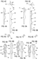
- the first 200 and the second 210 faces of the pin considered form a right angle between them, as clearly shown in Figure 4C
- the second zone 23 here has a first swollen portion - or first bulge - 231 juxtaposed and in the extension of the first zone 22, and a second swollen portion - or second bulge - 232 in the extension of the first bulge 231.
- Figures 5A and 5B relate to an embodiment which differs from that of the figures 4 in that the second swollen portion 232 has a recess 233 at the level of the distal part 21 of the spike.
- Figure 5B further differs by the angle between the two faces 200, 210 of the pin: this angle is here approximately 45°. This pin is therefore thinner and, all other things being equal, more flexible than that illustrated by the figures 4 .
- each spike comprises two recesses 233 and 234, substantially in the extension of one another. These recesses are capable of forming two openings 235, 236 in the extension of one another, with an appropriate reciprocal arrangement of two successive spikes.
- a variant of the embodiment of the Figures 7A, 7B, 7C is represented on the Figures 8A, 8B and 8C
- the difference lies in the opening 230 which is not closed at the distal end 21.
- a sort of tuning fork here constitutes the second zone 23 which benefits from an interesting flexibility both to serve as a product reservoir and to retain and guide the keratin fibers.
- FIGS. 9A, 9B and 9C relate to spikes 2 of the type presented above to which is added a lug or outgrowth 24 originating from a bulge and/or a convexity 232.
- this geometry is of interest for improving the guidance of the keratin fibers.
- FIGS. 10A and 10B illustrate a spike 2 which can be made in two ways: either by the juxtaposition in contact of two spikes whose first 200 and second 210 faces form an angle of 90° between them; or by a single spike whose first and second faces form an angle of 180°.
- two bulges 231, 232 are provided at the level of the second zone 23, and these two bulges come from the flat zone(s) 200, 210.
- the bulges are oriented at 180° to each other; they have a contact surface merged with a reference plane P.
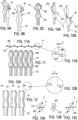
- FIGS 11, 11A and 11B show an embodiment according to which the pins 2 are delimited by a first flat face 200 and a second flat face 210 forming between them an angle of approximately 45°.
- the second zones 23 of the pins are formed by a succession of concave and convex curvatures.
- the arrangement of two adjacent pins is such that a difference E of approximately 0.01 mm can be measured along the longitudinal axis XX of the applicator device.
- the orientation of two adjacent pins is not the same since the second flat faces 210 are located alternately on either side of the longitudinal reference plane P, while the first faces 200 belong to the reference plane P. This arrangement makes it possible to form two substantially distinct openings 235, 236 in space.
- THE figures 12, 12A, 12B present an embodiment which differs from that of the Figures 11, 11A and 11B by the longitudinal implantation gap E between two pins. This gap is approximately ten times larger, so that the openings 235, 236 are not closed. The person skilled in the art chooses the most appropriate version.
- FIGS. 13A, 13B and 13C show three possible gaps between two longitudinally adjacent pins 2.
- two adjacent pins have a maximum overlapping surface at the level of their first flat faces 200; according to the Figure 13B , the overlapping surface is approximately half of the first 200 planar surfaces; according to the Figure 13C , only a small portion of the contact surface is provided.
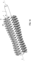
- FIG. 14 illustrates by a perspective a preferred embodiment.
- An interesting aspect of this embodiment concerns the distal openings 236 formed by two successive spikes 2, on several rows of spikes. These openings 236 serve as a reservoir for the fluid or pasty product. Such reservoirs are easily filled with product since they are arranged on the periphery of the volume occupied by the application device; the openings being moreover formed by two free ends of spikes, they are particularly flexible, which is interesting for repeated passages of the applicator devices through the wringers - small discs placed at the neck of the container.
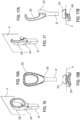
- FIGS 15, 15A and 15B relate to a solution where the second portion of the second zone 23 of the spike has a U shape whose apex is juxtaposed with the first zone 22 at the level of a longitudinal plane P.
- the Figure 15A clearly shows this arrangement.
- several rows of pins (six) as described above are provided, radially spaced on the core.
- Other types of pins 2 may be provided on a core 1, for example radially interposed between the U-shaped pins.
- the Figure 15B shows in more detail a pin 2 as described above.
- the spike comprises a first zone 22 embedded on the core, as already defined; the spike further comprises a second zone 23 here defined by a first part 231 whose two faces form an angle of 180° and belong to the reference plane P.
- the part 231 is located in the longitudinal extension of the first zone 22 and it is juxtaposed with overlap in the plane P with a second part 232, distal part, which projects on the other side of the plane P, as shown in particular by Figure 16B .
- the part 232 has an opening or closed loop at its distal end (not referenced but corresponding to the opening 236 of the other embodiments of the spikes).
- the spike is here “distributed” on either side of the plane P. It has all the characteristics and advantages of the other embodiments of the invention.
- FIGS 17, 17A and 17B relate to an embodiment close to that illustrated by the figures 16
- the essential difference lies in the shape of the second part 232, which here corresponds to a distally open hook.
- This embodiment more flexible than that of the figures 16, 16A, 16B , will therefore be chosen by the person skilled in the art when greater flexibility is required.
- the distal opening 236 is open here since it is defined by the hook 232.
- the number of rows of pins preferably varies from one to twenty-four, with pins and pin arrangements identical or not.
- the spikes can all be oriented in the same way on the same row or on all the spikes constituting the application device; the spikes can also have different orientations, for example alternating on either side of the longitudinal plane P.
Landscapes
- Physics & Mathematics (AREA)
- Geometry (AREA)
- Brushes (AREA)
- Coating Apparatus (AREA)
- Cleaning And Drying Hair (AREA)
Claims (11)
- Applikatorvorrichtung für ein Produkt flüssiger oder pastöser Art auf Keratinfasern, umfassend:- einen länglich geformten zentralen Kern (1), der sich entlang einer Längsachse XX erstreckt, und- mindestens eine Reihe länglicher Noppen (2), die ein erstes Ende (20) umfasst, das in den Kern eingelassen ist, und ein zweites freies Ende (21), wobei die Noppen (2) und der zentrale Kern (1) aus einem Stück gebildet sind,wobei mindestens einer der Noppen durch eine erste ebene Fläche (200) begrenzt ist, die mit einer Längsebene der Vorrichtung, der so genannten Bezugsebene P, zusammenfällt, die sich radial zum zentralen Kern (1) erstreckt, und durch eine zweite ebene Fläche, die mit der ersten ebene Fläche einen Winkel von etwa 180° bildet,und der mindestens eine Noppen (2) umfassend:- einen ersten Bereich (22), der in den zentralen Kern (1) eingelassen ist und einen im Wesentlichen konstanten Querschnitt hat, und- einen zweiten Bereich (23) mit variablem Querschnitt, der sich im Wesentlichen in der Längsverlängerung des ersten Bereichs (22) befindet,wobei der zweite Bereich (23) mindestens einen ersten Abschnitt (231), der nebeneinander und in Verlängerung des ersten Bereichs (22) angeordnet ist, und einen zweiten Abschnitt (232) umfasst, der nebeneinander angeordnet ist und sich mit dem ersten Abschnitt (231) gemäß der Bezugsebene P überlappt.
- Vorrichtung nach Anspruch 1, dadurch gekennzeichnet, dass der erste Abschnitt (231) eine zur Ebene P gehörende Seite beinhaltet, wobei der zweite Abschnitt (232) von der anderen Seite der Ebene P herausragt.
- Vorrichtung nach Anspruch 1 oder 2, dadurch gekennzeichnet, dass der erste Abschnitt (231) eine erste Erhebung umfasst und der zweite Abschnitt (232) eine zweite Erhebung umfasst, die anders als die erste Erhebung ausgerichtet ist.
- Vorrichtung nach einem der Ansprüche 1 bis 3, dadurch gekennzeichnet, dass der zweite Abschnitt (232) des zweiten Bereichs eine Öffnung (236) beinhaltet.
- Vorrichtung nach Anspruch 4, dadurch gekennzeichnet, dass der zweite Abschnitt (232) des zweiten Bereichs (23) eine U-Form aufweist, die sich im Wesentlichen parallel zu dieser Bezugsebene auf der anderen Seite der Bezugsebene P relativ zum ersten Abschnitt erstreckt, wobei die U-Form die Öffnung (236) teilweise begrenzt.
- Vorrichtung nach Anspruch 2, dadurch gekennzeichnet, dass der zweite Abschnitt (232) des zweiten Bereichs (23) eine geschlossene Schleife aufweist, die sich im Wesentlichen parallel zu dieser Bezugsebene auf der anderen Seite der Bezugsebene P relativ zum ersten Abschnitt erstreckt, wobei die geschlossene Schleife eine Öffnung (236) begrenzt.
- Vorrichtung nach Anspruch 2, dadurch gekennzeichnet, dass der zweite Abschnitt (232) des zweiten Bereichs (23) eine distal offene Hakenform aufweist, die sich im Wesentlichen parallel zu dieser Bezugsebene auf der anderen Seite der Bezugsebene P relativ zum ersten Abschnitt erstreckt, wobei die offene Hakenform eine Öffnung (236) teilweise abgrenzt.
- Vorrichtung nach einem der Ansprüche 1 bis 7, dadurch gekennzeichnet, dass mindestens zwei der einer Reihe bildenden Noppen (2) eine identische Ausrichtung aufweisen.
- Vorrichtung nach einem der Ansprüche 1 bis 8, dadurch gekennzeichnet, dass mindestens zwei der einer Reihe bildenden Noppen (2) eine unterschiedliche Ausrichtung aufweisen.
- Vorrichtung nach einem der Ansprüche 1 bis 9, dadurch gekennzeichnet, dass der gemäß der Achse XX gemessene Abstand zwischen zwei aufeinanderfolgenden Noppen negativ, null oder positiv, kleiner als etwa 2 Millimeter sein kann.
- Vorrichtung nach einem der Ansprüche 1 bis 10, dadurch gekennzeichnet, dass sich der zweite Bereich des/der Noppen nach einer Abfolge von konkaven und konvexen Krümmungen erstreckt
Applications Claiming Priority (3)
| Application Number | Priority Date | Filing Date | Title |
|---|---|---|---|
| FR1551605A FR3032869B1 (fr) | 2015-02-25 | 2015-02-25 | Dispositif applicateur d'un produit de type fluide ou pateux sur des fibres keratiniques. |
| PCT/FR2016/050432 WO2016135423A1 (fr) | 2015-02-25 | 2016-02-24 | Dispositif applicateur d'un produit de type fluide ou pateux sur des fibres keratiniques |
| EP16714981.4A EP3261487B1 (de) | 2015-02-25 | 2016-02-24 | Applikatorvorrichtung zum auftragen eines produktes vom flüssigen oder pastösen typ auf keratinfasern |
Related Parent Applications (2)
| Application Number | Title | Priority Date | Filing Date |
|---|---|---|---|
| EP16714981.4A Division EP3261487B1 (de) | 2015-02-25 | 2016-02-24 | Applikatorvorrichtung zum auftragen eines produktes vom flüssigen oder pastösen typ auf keratinfasern |
| EP16714981.4A Division-Into EP3261487B1 (de) | 2015-02-25 | 2016-02-24 | Applikatorvorrichtung zum auftragen eines produktes vom flüssigen oder pastösen typ auf keratinfasern |
Publications (3)
| Publication Number | Publication Date |
|---|---|
| EP4098148A1 EP4098148A1 (de) | 2022-12-07 |
| EP4098148C0 EP4098148C0 (de) | 2025-04-09 |
| EP4098148B1 true EP4098148B1 (de) | 2025-04-09 |
Family
ID=53059282
Family Applications (2)
| Application Number | Title | Priority Date | Filing Date |
|---|---|---|---|
| EP16714981.4A Active EP3261487B1 (de) | 2015-02-25 | 2016-02-24 | Applikatorvorrichtung zum auftragen eines produktes vom flüssigen oder pastösen typ auf keratinfasern |
| EP22186792.2A Active EP4098148B1 (de) | 2015-02-25 | 2016-02-24 | Vorrichtung zum auftragen eines flüssigen oder pastenartigen produkts auf keratinfasern |
Family Applications Before (1)
| Application Number | Title | Priority Date | Filing Date |
|---|---|---|---|
| EP16714981.4A Active EP3261487B1 (de) | 2015-02-25 | 2016-02-24 | Applikatorvorrichtung zum auftragen eines produktes vom flüssigen oder pastösen typ auf keratinfasern |
Country Status (5)
| Country | Link |
|---|---|
| US (1) | US11478061B2 (de) |
| EP (2) | EP3261487B1 (de) |
| JP (1) | JP7001480B2 (de) |
| FR (1) | FR3032869B1 (de) |
| WO (1) | WO2016135423A1 (de) |
Families Citing this family (16)
| Publication number | Priority date | Publication date | Assignee | Title |
|---|---|---|---|---|
| FR3039381B1 (fr) | 2015-07-27 | 2019-10-18 | Albea Services | Applicateur pour produit cosmetique et ensemble applicateur associe |
| FR3070842B1 (fr) | 2017-09-12 | 2021-07-16 | Oreal | Applicateur cosmetique |
| FR3070843B1 (fr) * | 2017-09-12 | 2021-07-30 | Oreal | Applicateur cosmetique |
| FR3070841B1 (fr) * | 2017-09-12 | 2021-07-16 | Oreal | Applicateur cosmetique |
| FR3070839B1 (fr) * | 2017-09-12 | 2025-04-11 | Oreal | Applicateur cosmetique |
| WO2020025861A1 (fr) * | 2018-08-03 | 2020-02-06 | Societe Industrielle De Matieres Plastiques | Dispositif applicateur d'un produit fluide |
| WO2020058583A1 (fr) * | 2018-09-19 | 2020-03-26 | Societe Industrielle De Matieres Plastiques | Dispositif applicateur d'un produit fluide |
| WO2020120846A1 (fr) * | 2018-12-10 | 2020-06-18 | Societe Industrielle De Matieres Plastiques | Kit d'élaboration d'une brosse pour applicateur de produits cosmétiques |
| FR3090298B1 (fr) * | 2018-12-19 | 2021-04-30 | Oreal | Applicateur pour appliquer un produit cosmétique (F) sur les cils et/ou sourcils. |
| FR3090295B1 (fr) * | 2018-12-19 | 2021-09-10 | Oreal | Procédé de génération d’un modèle numérique d’applicateur de produit cosmétique |
| USD938736S1 (en) * | 2019-11-06 | 2021-12-21 | Simp | Mascara brush |
| CN117580488A (zh) * | 2021-06-29 | 2024-02-20 | 马蒂埃尔斯塑胶工业公司 | 用于将流体或糊状类型产品涂抹到角质纤维上的涂抹器装置 |
| FR3129573B1 (fr) * | 2021-11-26 | 2025-04-11 | Lvmh Rech | Brosse pour mascara |
| USD1006458S1 (en) * | 2022-05-30 | 2023-12-05 | Simp | Mascara brush |
| USD1008665S1 (en) * | 2022-06-07 | 2023-12-26 | Simp | Mascara brush |
| GB2634027A (en) * | 2023-09-26 | 2025-04-02 | Dyson Technology Ltd | A hair apparatus |
Family Cites Families (20)
| Publication number | Priority date | Publication date | Assignee | Title |
|---|---|---|---|---|
| BE794511A (fr) * | 1972-01-28 | 1973-05-16 | World Inventions Ltd | Perfectionnements apportes aux articles de peignage |
| FR2505633B1 (fr) * | 1981-05-18 | 1985-09-06 | Oreal | Brosse a cils perfectionnee, procede pour sa fabrication et dispositif pour la mise en oeuvre de ce procede |
| US5611361A (en) | 1995-06-14 | 1997-03-18 | Revlon Consumer Products Corporation | Mascara application system |
| JP4275883B2 (ja) * | 1999-07-21 | 2009-06-10 | ロレアル | 毛、特に睫毛又は眉に物質を塗るための装置 |
| FR2796530B1 (fr) * | 1999-07-21 | 2001-09-21 | Oreal | Dispositif pour le peignage des cils ou des sourcils et dispositif de conditionnement et d'application ainsi equipe |
| FR2796529B1 (fr) * | 1999-07-21 | 2001-09-21 | Oreal | Dispositif de conditionnement et d'application d'un produit sur les cils ou les sourcils |
| FR2810860B1 (fr) | 2000-06-28 | 2003-02-21 | Oreal | Dispositif pour l'application d'un produit sur les cils ou les sourcils |
| FR2872394B1 (fr) | 2004-07-01 | 2007-04-20 | Oreal | Dispositif pour l'application d'un produit sur les fibres keratiniques |
| FR2890837B1 (fr) * | 2005-09-21 | 2007-12-28 | Saint Laurent Parfums | Instrument d'application a parois d'un produit sur les cils ou les sourcils |
| FR2902984B1 (fr) | 2006-06-28 | 2009-03-20 | Oreal | Dispositif pour l'application d'un produit sur les cils ou les sourcils. |
| FR2922420B1 (fr) * | 2007-10-23 | 2011-04-01 | Oreal | Applicateur pour l'application d'un produit sur les cils ou les sourcils |
| FR2930874A1 (fr) * | 2008-04-18 | 2009-11-13 | Ile M V R Soc Civ Soc Civ | Dispositif applicateur d'un produit cosmetique fluide ou pateux, typiquement du mascara. |
| EP2196106B9 (de) * | 2008-12-12 | 2013-10-02 | LAFFON S.r.l. | Verbundstoffapplikator für dekorative Produkte in flüssiger, viskoser oder pastöser Form |
| DE102009035390A1 (de) | 2009-07-30 | 2011-02-03 | Geka Gmbh | Mascara-Bürste mit Wimpernrückhalteorgan |
| FR2951359B1 (fr) | 2009-10-15 | 2019-12-27 | L'oreal | Dispositif pour appliquer un produit sur les cils ou les sourcils. |
| DE202010017160U1 (de) * | 2010-12-30 | 2012-04-03 | Geka Gmbh | Applikatoreinrichtung, insbesondere für einen Kosmetikapplikator, Applikator, insbesondere Kosmetikapplikator aufweisend die Applikatoreinrichtung sowie Applikationseinheit, insbesondere Kosmetikeinheit aufweisend die Applikatoreinrichtung |
| FR2993441A1 (fr) | 2012-07-20 | 2014-01-24 | Montaigu Dev | Moule modulaire pour la realisation de brosses de mascara |
| FR3006566B1 (fr) * | 2013-06-06 | 2018-04-27 | L'oreal | Applicateur pour appliquer un produit sur les cils et/ou les sourcils |
| US20150020332A1 (en) * | 2013-07-19 | 2015-01-22 | Christophe Jacob | Molded Cosmetic Applicators And Mold Therefor |
| US20160022012A1 (en) * | 2014-07-22 | 2016-01-28 | Elc Management Llc | Molded Cosmetic Applicators With Perforated Bristles And Mold Therefor |
-
2015
- 2015-02-25 FR FR1551605A patent/FR3032869B1/fr active Active
-
2016
- 2016-02-24 JP JP2017563389A patent/JP7001480B2/ja active Active
- 2016-02-24 US US15/553,881 patent/US11478061B2/en active Active
- 2016-02-24 WO PCT/FR2016/050432 patent/WO2016135423A1/fr not_active Ceased
- 2016-02-24 EP EP16714981.4A patent/EP3261487B1/de active Active
- 2016-02-24 EP EP22186792.2A patent/EP4098148B1/de active Active
Also Published As
| Publication number | Publication date |
|---|---|
| EP4098148C0 (de) | 2025-04-09 |
| US20180242714A1 (en) | 2018-08-30 |
| JP7001480B2 (ja) | 2022-01-19 |
| FR3032869A1 (fr) | 2016-08-26 |
| WO2016135423A1 (fr) | 2016-09-01 |
| JP2018518269A (ja) | 2018-07-12 |
| EP4098148A1 (de) | 2022-12-07 |
| FR3032869B1 (fr) | 2018-05-11 |
| US11478061B2 (en) | 2022-10-25 |
| EP3261487C0 (de) | 2023-10-18 |
| EP3261487A1 (de) | 2018-01-03 |
| EP3261487B1 (de) | 2023-10-18 |
Similar Documents
| Publication | Publication Date | Title |
|---|---|---|
| EP4098148B1 (de) | Vorrichtung zum auftragen eines flüssigen oder pastenartigen produkts auf keratinfasern | |
| EP3282888B1 (de) | Vorrichtung zur applikation eines fliessfähigen oder pastösen produktes auf keratinfasern | |
| CA2314470C (fr) | Dispositif de conditionnement et d'application d'un produit sur les cils ou les sourcils | |
| EP1115303B1 (de) | Vorrichtung zum auftragen eines pruduktes auf keratinische fasern | |
| EP3468412B1 (de) | Applikatorvorrichtung zum auftragen eines flüssigen oder pastösen produkts auf keratinfasern | |
| EP3193663B1 (de) | Applikatorvorrichtung zum auftragen eines fliessfähigen produkts über eine komplexen oberfläche | |
| FR2961384B1 (fr) | Applicateur d'un produit cosmetique, de maquillage ou de soin, sur les cils ou les sourcils | |
| EP2265146B1 (de) | Vorrichtung zum auftragen eines flüssigen oder pastösen kosmetikprodukts, insbesondere von mascara | |
| FR2951359A1 (fr) | Dispositif pour appliquer un produit sur les cils ou les sourcils. | |
| FR2969470A1 (fr) | Nouveau dispositif applicateur d'un fluide sur des fibres keratiniques | |
| EP1157629A1 (de) | Vorrichtung zum Auftragen eines kosmetischen oder pflegenden Produktes, insbesondere auf Wimpern oder Augenbrauen | |
| WO2017115022A1 (fr) | Dispositif applicateur de produit fluide ou pateux sur des fibres keratiniques. | |
| EP3013175B1 (de) | Vorrichtung zum auftragen eines kosmetikprodukts | |
| EP2865292B1 (de) | Applikator für Kosmetikprodukt, und entspechende Applikatoranordnung | |
| WO2020058645A1 (fr) | Dispositif applicateur d'un produit fluide | |
| EP2865293A1 (de) | Applikator für Kosmetikprodukt, und entspechende Applikatoranordnung | |
| FR2937514A1 (fr) | Dispositif applicateur d'un produit cosmetique fluide ou pateux, typiquement du mascara | |
| EP3629833A1 (de) | Applikator zum auftragen von produkten auf keratinfasern mit komplexkern | |
| FR2984091A1 (fr) | Applicateur pour appliquer un produit cosmetique sur les cils ou les sourcils, comportant un organe d'application moule. | |
| FR3024342A1 (fr) | Embout applicateur pour produit cosmetique, applicateur et ensemble applicateur associes | |
| FR3059877A1 (fr) | "applicateur pour produit cosmetique et ensemble applicateur associe" |
Legal Events
| Date | Code | Title | Description |
|---|---|---|---|
| PUAI | Public reference made under article 153(3) epc to a published international application that has entered the european phase |
Free format text: ORIGINAL CODE: 0009012 |
|
| STAA | Information on the status of an ep patent application or granted ep patent |
Free format text: STATUS: THE APPLICATION HAS BEEN PUBLISHED |
|
| AC | Divisional application: reference to earlier application |
Ref document number: 3261487 Country of ref document: EP Kind code of ref document: P |
|
| AK | Designated contracting states |
Kind code of ref document: A1 Designated state(s): AL AT BE BG CH CY CZ DE DK EE ES FI FR GB GR HR HU IE IS IT LI LT LU LV MC MK MT NL NO PL PT RO RS SE SI SK SM TR |
|
| STAA | Information on the status of an ep patent application or granted ep patent |
Free format text: STATUS: REQUEST FOR EXAMINATION WAS MADE |
|
| 17P | Request for examination filed |
Effective date: 20230412 |
|
| RBV | Designated contracting states (corrected) |
Designated state(s): AL AT BE BG CH CY CZ DE DK EE ES FI FR GB GR HR HU IE IS IT LI LT LU LV MC MK MT NL NO PL PT RO RS SE SI SK SM TR |
|
| RAP3 | Party data changed (applicant data changed or rights of an application transferred) |
Owner name: SOCIETE INDUSTRIELLE DE MATIERES PLASTIQUES |
|
| GRAP | Despatch of communication of intention to grant a patent |
Free format text: ORIGINAL CODE: EPIDOSNIGR1 |
|
| STAA | Information on the status of an ep patent application or granted ep patent |
Free format text: STATUS: GRANT OF PATENT IS INTENDED |
|
| INTG | Intention to grant announced |
Effective date: 20241213 |
|
| GRAS | Grant fee paid |
Free format text: ORIGINAL CODE: EPIDOSNIGR3 |
|
| GRAA | (expected) grant |
Free format text: ORIGINAL CODE: 0009210 |
|
| STAA | Information on the status of an ep patent application or granted ep patent |
Free format text: STATUS: THE PATENT HAS BEEN GRANTED |
|
| AC | Divisional application: reference to earlier application |
Ref document number: 3261487 Country of ref document: EP Kind code of ref document: P |
|
| AK | Designated contracting states |
Kind code of ref document: B1 Designated state(s): AL AT BE BG CH CY CZ DE DK EE ES FI FR GB GR HR HU IE IS IT LI LT LU LV MC MK MT NL NO PL PT RO RS SE SI SK SM TR |
|
| REG | Reference to a national code |
Ref country code: GB Ref legal event code: FG4D Free format text: NOT ENGLISH |
|
| REG | Reference to a national code |
Ref country code: CH Ref legal event code: EP |
|
| REG | Reference to a national code |
Ref country code: DE Ref legal event code: R096 Ref document number: 602016091894 Country of ref document: DE |
|
| REG | Reference to a national code |
Ref country code: IE Ref legal event code: FG4D Free format text: LANGUAGE OF EP DOCUMENT: FRENCH |
|
| U01 | Request for unitary effect filed |
Effective date: 20250509 |
|
| U07 | Unitary effect registered |
Designated state(s): AT BE BG DE DK EE FI FR IT LT LU LV MT NL PT RO SE SI Effective date: 20250516 |
|
| PG25 | Lapsed in a contracting state [announced via postgrant information from national office to epo] |
Ref country code: ES Free format text: LAPSE BECAUSE OF FAILURE TO SUBMIT A TRANSLATION OF THE DESCRIPTION OR TO PAY THE FEE WITHIN THE PRESCRIBED TIME-LIMIT Effective date: 20250409 |
|
| PG25 | Lapsed in a contracting state [announced via postgrant information from national office to epo] |
Ref country code: GR Free format text: LAPSE BECAUSE OF FAILURE TO SUBMIT A TRANSLATION OF THE DESCRIPTION OR TO PAY THE FEE WITHIN THE PRESCRIBED TIME-LIMIT Effective date: 20250710 Ref country code: NO Free format text: LAPSE BECAUSE OF FAILURE TO SUBMIT A TRANSLATION OF THE DESCRIPTION OR TO PAY THE FEE WITHIN THE PRESCRIBED TIME-LIMIT Effective date: 20250709 |
|
| PG25 | Lapsed in a contracting state [announced via postgrant information from national office to epo] |
Ref country code: PL Free format text: LAPSE BECAUSE OF FAILURE TO SUBMIT A TRANSLATION OF THE DESCRIPTION OR TO PAY THE FEE WITHIN THE PRESCRIBED TIME-LIMIT Effective date: 20250409 |
|
| PG25 | Lapsed in a contracting state [announced via postgrant information from national office to epo] |
Ref country code: HR Free format text: LAPSE BECAUSE OF FAILURE TO SUBMIT A TRANSLATION OF THE DESCRIPTION OR TO PAY THE FEE WITHIN THE PRESCRIBED TIME-LIMIT Effective date: 20250409 |
|
| PG25 | Lapsed in a contracting state [announced via postgrant information from national office to epo] |
Ref country code: RS Free format text: LAPSE BECAUSE OF FAILURE TO SUBMIT A TRANSLATION OF THE DESCRIPTION OR TO PAY THE FEE WITHIN THE PRESCRIBED TIME-LIMIT Effective date: 20250709 |
|
| PG25 | Lapsed in a contracting state [announced via postgrant information from national office to epo] |
Ref country code: IS Free format text: LAPSE BECAUSE OF FAILURE TO SUBMIT A TRANSLATION OF THE DESCRIPTION OR TO PAY THE FEE WITHIN THE PRESCRIBED TIME-LIMIT Effective date: 20250809 |