EP4097445B1 - Verfahren und systeme zur zerstörungsfreien schätzung der grösse von streuenden teilchen - Google Patents
Verfahren und systeme zur zerstörungsfreien schätzung der grösse von streuenden teilchen Download PDFInfo
- Publication number
- EP4097445B1 EP4097445B1 EP21747699.3A EP21747699A EP4097445B1 EP 4097445 B1 EP4097445 B1 EP 4097445B1 EP 21747699 A EP21747699 A EP 21747699A EP 4097445 B1 EP4097445 B1 EP 4097445B1
- Authority
- EP
- European Patent Office
- Prior art keywords
- sample
- polarized component
- polarized light
- parallel
- rates
- Prior art date
- Legal status (The legal status is an assumption and is not a legal conclusion. Google has not performed a legal analysis and makes no representation as to the accuracy of the status listed.)
- Active
Links
Images


Classifications
-
- G—PHYSICS
- G01—MEASURING; TESTING
- G01N—INVESTIGATING OR ANALYSING MATERIALS BY DETERMINING THEIR CHEMICAL OR PHYSICAL PROPERTIES
- G01N15/00—Investigating characteristics of particles; Investigating permeability, pore-volume or surface-area of porous materials
- G01N15/02—Investigating particle size or size distribution
- G01N15/0205—Investigating particle size or size distribution by optical means
- G01N15/0211—Investigating a scatter or diffraction pattern
-
- G—PHYSICS
- G01—MEASURING; TESTING
- G01N—INVESTIGATING OR ANALYSING MATERIALS BY DETERMINING THEIR CHEMICAL OR PHYSICAL PROPERTIES
- G01N11/00—Investigating flow properties of materials, e.g. viscosity, plasticity; Analysing materials by determining flow properties
-
- G—PHYSICS
- G01—MEASURING; TESTING
- G01N—INVESTIGATING OR ANALYSING MATERIALS BY DETERMINING THEIR CHEMICAL OR PHYSICAL PROPERTIES
- G01N15/00—Investigating characteristics of particles; Investigating permeability, pore-volume or surface-area of porous materials
- G01N15/02—Investigating particle size or size distribution
- G01N15/0205—Investigating particle size or size distribution by optical means
- G01N15/0227—Investigating particle size or size distribution by optical means using imaging; using holography
-
- G—PHYSICS
- G01—MEASURING; TESTING
- G01N—INVESTIGATING OR ANALYSING MATERIALS BY DETERMINING THEIR CHEMICAL OR PHYSICAL PROPERTIES
- G01N15/00—Investigating characteristics of particles; Investigating permeability, pore-volume or surface-area of porous materials
- G01N15/10—Investigating individual particles
- G01N15/14—Optical investigation techniques, e.g. flow cytometry
- G01N15/1434—Optical arrangements
-
- G—PHYSICS
- G01—MEASURING; TESTING
- G01N—INVESTIGATING OR ANALYSING MATERIALS BY DETERMINING THEIR CHEMICAL OR PHYSICAL PROPERTIES
- G01N15/00—Investigating characteristics of particles; Investigating permeability, pore-volume or surface-area of porous materials
- G01N15/10—Investigating individual particles
- G01N15/14—Optical investigation techniques, e.g. flow cytometry
- G01N15/1468—Optical investigation techniques, e.g. flow cytometry with spatial resolution of the texture or inner structure of the particle
-
- G—PHYSICS
- G01—MEASURING; TESTING
- G01N—INVESTIGATING OR ANALYSING MATERIALS BY DETERMINING THEIR CHEMICAL OR PHYSICAL PROPERTIES
- G01N11/00—Investigating flow properties of materials, e.g. viscosity, plasticity; Analysing materials by determining flow properties
- G01N11/10—Investigating flow properties of materials, e.g. viscosity, plasticity; Analysing materials by determining flow properties by moving a body within the material
- G01N11/16—Investigating flow properties of materials, e.g. viscosity, plasticity; Analysing materials by determining flow properties by moving a body within the material by measuring damping effect upon oscillatory body
- G01N11/162—Oscillations being torsional, e.g. produced by rotating bodies
- G01N11/165—Sample held between two members substantially perpendicular to axis of rotation, e.g. parallel plate viscometer
-
- G—PHYSICS
- G01—MEASURING; TESTING
- G01N—INVESTIGATING OR ANALYSING MATERIALS BY DETERMINING THEIR CHEMICAL OR PHYSICAL PROPERTIES
- G01N15/00—Investigating characteristics of particles; Investigating permeability, pore-volume or surface-area of porous materials
- G01N15/01—Investigating characteristics of particles; Investigating permeability, pore-volume or surface-area of porous materials specially adapted for biological cells, e.g. blood cells
-
- G—PHYSICS
- G01—MEASURING; TESTING
- G01N—INVESTIGATING OR ANALYSING MATERIALS BY DETERMINING THEIR CHEMICAL OR PHYSICAL PROPERTIES
- G01N11/00—Investigating flow properties of materials, e.g. viscosity, plasticity; Analysing materials by determining flow properties
- G01N2011/006—Determining flow properties indirectly by measuring other parameters of the system
- G01N2011/008—Determining flow properties indirectly by measuring other parameters of the system optical properties
-
- G—PHYSICS
- G01—MEASURING; TESTING
- G01N—INVESTIGATING OR ANALYSING MATERIALS BY DETERMINING THEIR CHEMICAL OR PHYSICAL PROPERTIES
- G01N15/00—Investigating characteristics of particles; Investigating permeability, pore-volume or surface-area of porous materials
- G01N15/02—Investigating particle size or size distribution
- G01N15/0205—Investigating particle size or size distribution by optical means
- G01N15/0211—Investigating a scatter or diffraction pattern
- G01N2015/0222—Investigating a scatter or diffraction pattern from dynamic light scattering, e.g. photon correlation spectroscopy
-
- G—PHYSICS
- G01—MEASURING; TESTING
- G01N—INVESTIGATING OR ANALYSING MATERIALS BY DETERMINING THEIR CHEMICAL OR PHYSICAL PROPERTIES
- G01N15/00—Investigating characteristics of particles; Investigating permeability, pore-volume or surface-area of porous materials
- G01N15/10—Investigating individual particles
- G01N15/14—Optical investigation techniques, e.g. flow cytometry
- G01N15/1434—Optical arrangements
- G01N2015/1454—Optical arrangements using phase shift or interference, e.g. for improving contrast
-
- G—PHYSICS
- G01—MEASURING; TESTING
- G01N—INVESTIGATING OR ANALYSING MATERIALS BY DETERMINING THEIR CHEMICAL OR PHYSICAL PROPERTIES
- G01N15/00—Investigating characteristics of particles; Investigating permeability, pore-volume or surface-area of porous materials
- G01N15/10—Investigating individual particles
- G01N15/14—Optical investigation techniques, e.g. flow cytometry
- G01N2015/1493—Particle size
Definitions
- the method according to the present invention is defined by claim 1.
- the apparatus according to the present invention is defined in claim 9.
- the dependent claims define preferred implementations of the invention. Accordingly, the methods and systems disclosed herein address one or more issue identified above by facilitating the sizing of scattering particles in both liquid and solid specimens using non-ionizing light rays and without contacting the specimen or manipulating it in any way.
- the invention provides a method for non-destructively estimating an average size of scattering particles in a sample, including: transmitting, using a coherent light source, polarized light, for instance linearly polarized light, to the sample; obtaining, using a detector, polarized light reflected from the sample, the polarized light comprising a parallel polarized component and a perpendicular polarized component; determining, using a processor, speckle decorrelation rates for the parallel polarized component and the perpendicular polarized component; and estimating, using the processor, the average size of scattering particles in the sample based on the speckle decorrelation rates for the parallel polarized component and the perpendicular polarized component.
- the invention provides a method for determining a spatial map of a frequency-dependent modulus in a sample, including: obtaining, using a detector and at a plurality of time points, a plurality of speckle frames of the sample using parallel and perpendicular polarized light, each of the plurality of speckle frames comprising a plurality of pixels; determining, using a processor, speckle intensity autocorrelation curves for each of the plurality of pixels for each of the parallel and perpendicular light based on the plurality of speckle frames, estimating, using the processor, a distribution of scattering particle size in the sample based on the speckle intensity autocorrelation curves; determining, using the processor, a mean square displacement of local scattering particles based on the speckle intensity autocorrelation curves; and determining, using the processor and for each of the plurality of pixels, at least one of a frequency-dependent shear viscoelastic modulus G(x,y,w), an elastic modulus G'(x,y,w
- the invention provides an apparatus for non-destructively estimating an average size of scattering particles in a sample, including: a coherent light source; a detector; and a processor in communication with the coherent light source and the detector, the processor being configured to: control the coherent light source to transmit linearly polarized light to the sample, control the detector to obtain polarized light reflected from the sample, the polarized light comprising a parallel polarized component and a perpendicular polarized component, determining speckle decorrelation rates for the parallel polarized component and the perpendicular polarized component, and estimate the average size of scattering particles in the sample based on the speckle decorrelation rates for the parallel polarized component and the perpendicular polarized component.
- the invention provides an apparatus for determining a spatial map of a frequency-dependent modulus in a sample, including: a detector; and a processor in communication with the detector, the processor being configured to: control the detector to obtain, at a plurality of time points, a plurality of speckle frames of the sample using parallel and perpendicular polarized light, each of the plurality of speckle frames comprising a plurality of pixels, determine speckle intensity autocorrelation curves for each of the plurality of pixels for each of the parallel and perpendicular light based on the plurality of speckle frames, estimate a distribution of scattering particle size in the sample based on the speckle intensity autocorrelation curves, determine a mean square displacement of local scattering particles based on the speckle intensity autocorrelation curves, and determine, for each of the plurality of pixels, at least one of a frequency-dependent shear viscoelastic modulus G(x,y,w), an elastic modulus G'(x,y,w), or an viscous
- the invention provides a method for determining a spatial map of particle sizes in a sample, including: obtaining, using a detector and at a plurality of time points, a plurality of speckle frames of the sample using parallel and perpendicular polarized light, each of the plurality of speckle frames including a plurality of pixels; determining, using a processor, speckle intensity autocorrelation curves for each of the plurality of pixels for each of the parallel and perpendicular light based on the plurality of speckle frames, estimating, using the processor, a distribution of scattering particle size in the sample based on the speckle intensity autocorrelation curves; determining, using the processor, a mean square displacement of local scattering particles based on the speckle intensity autocorrelation curves; and determining, using the processor and for each of the plurality of pixels, a spatial map of scattering particle size a(x,y) for the sample based on the distribution of speckle intensity autocorrelation, decorrelation or relaxation times.
- the invention provides an apparatus for determining a spatial map of particle sizes in a sample, including: a detector; and a processor in communication with the detector, the processor being configured to: control the detector to obtain, at a plurality of time points, a plurality of speckle frames of the sample using parallel and perpendicular polarized light, each of the plurality of speckle frames including a plurality of pixels, determine speckle intensity autocorrelation curves for each of the plurality of pixels for each of the parallel and perpendicular light based on the plurality of speckle frames, estimate a distribution of scattering particle size in the sample based on the speckle intensity autocorrelation curves, determine a mean square displacement of local scattering particles based on the speckle intensity autocorrelation curves, and determine, for each of the plurality of pixels, a spatial map of scattering particle size a(x,y) for the sample based on the distribution of speckle intensity autocorrelation times.
- mechanisms (which can include systems, methods, and apparatus) for non-destructively estimating an average size of scattering particles in a sample are provided.
- LSM complex viscoelastic or shear modulus
- Laser speckle microrheology provides a research tool for investigating the link between the viscoelastic properties of the tissue microenvironment and its spatial variability with the clinical symptoms of disease onset and progression.
- Most of the existing techniques only provide the information about elastic properties of the tissue, at bulk scales.
- the LSM on the other hand, enables non-contact mapping of both viscous (liquid-like) and elastic (solid-like) behaviors under different loading rates, as best characterized by the frequency-dependent viscoelastic modulus also termed complex shear modulus, G ( ⁇ ). This is significant because it turns out that the interplay between viscous and elastic traits may additionally modify the malignant behavior, in ways not explained by elasticity alone. Moreover, the spatial distribution of elastic and viscous traits additionally modulate the malignant progression, in ways not readily evident from bulk or ensemble averaged properties.
- embodiments of the present disclosure provide improvements over previous work of the inventors including that of US Patent 10,359,361 , entitled “Laser speckle micro-rheology in characterization of biomechanical properties of tissues,” which is herein incorporated by reference in its entirety.
- the laser speckle microrheology (LSM) framework is detailed and validated for quantifying the spatially-variant, frequency-dependent viscoelastic behavior of biological tissues, with additional information on measuring spatially-variant optical properties and light scattering particle size distribution from time varying speckle patterns obtained at different polarization states.
- Laser speckle is a granular intensity pattern that arises when a turbid material such as biological tissue is illuminated by a coherent beam of light.
- Brownian distribution of scattering particles induces speckle intensity fluctuations.
- speckle fluctuations are therefore modulated by the scales and extent of these thermal movements and in turn the viscoelastic properties of their surrounding environment.
- the size of light scattering particles is an important factor that modulates the rate of speckle fluctuations.
- Algorithms have previously been devised to estimate the average hydro-dynamic size of endogenous scattering particles in biofluids and colloids.
- the prior approach was based on measuring the hydrodynamic radius of scattering particles from the spatial reflectance profile by evaluating the temporally-averaged speckle intensity acquired at the parallel polarization state, with respect to the polarization state of the illumination beam. The resulting intensity pattern was used to measure the diffuse reflectance profile (DRP) in the parallel polarization state.
- DRP diffuse reflectance profile
- the DRP in turn exhibited a unique spatial pattern that was related to average hydro-dynamic radius of scattering particles.
- DRP DRP evolves from a bilobular pattern to an elliptical form and eventually to a quadrifolium or clover-like shape. Nevertheless, this approach was only applicable to biological fluids with larger scattering particles and did not present sufficient sensitivity for evaluating the scattering particle size in soft tissues where the unknown scattering particle size distribution is skewed towards significantly smaller particles.
- the current invention describes an alternative particle sizing approach, pertaining to the spatial mapping of the viscoelastic modulus, G, and the scattering particle size, a, in heterogeneous soft tissue.
- it entails methods for quantifying the heterogeneity of both a and G, and also for investigating the frequency-dependence of G with knowledge of spatially variant modulus and scattering particle sizes.
- the present disclosure describes a particle sizing approach that is based on evaluating the speckle intensity autocorrelation function at two polarization states such as parallel and perpendicular with respect to the illumination state. Analysis of the time-dependent ratio of the log of the speckle intensity autocorrelation function at perpendicular and polarizations states is expected to yield the scattering particle size distribution.
- a second aspect of the present disclosure is the capability to obtain a 3D G(x, y, w) and subsequently both the elastic and viscous moduli of G' and G" maps from tissue. This is made possible by knowing the spatial-dependence of scattering particle size, a.
- a third aspect of the present disclosure is with regard to quantifying the heterogeneities in the modulus G(x, y, ⁇ ), and particle size variations, a, both of which are known to have significant clinical implications, such as in the context of tumor-stroma interactions in the field of cancer biomechanics.
- the optical opacity and turbidity of biological tissues stems from the refractive index mismatches between structural fibers and cell nuclei (n-1.4-1.45) and their background of cytoplasm (n ⁇ 1.36) or extracellular fluid (n ⁇ 1.34). These refractive index mismatches are the source of scattering signal and the optical properties of tissue. Refractive index variations may be either treated as a continuum of length scales or regarded as granular scattering particles of a given size distribution. The current invention takes the latter approach.
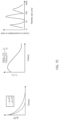
- FIG. 1A provides a diagram of an embodiment of an LSM platform showing an LSM optical setup.
- Light from a continuous-wave (CW) laser is passed through a polarization switch.
- this polarization switch the light is vertically polarized.
- One embodiment of the polarization switch is shown in the inset.
- the polarized beam is split into two beams using a beam splitter (BS).
- One of the vertically polarized beams passes through polarizing beam splitter (PBS) to a quarter waveplate (QWP), transforming into circular polarization.
- PBS polarizing beam splitter
- QWP quarter waveplate
- the beam is then reflected off a mirror, which flips the circular polarization direction.
- the beam is then passed through the same QWP, returning to linear polarization, which is rotated 90°, creating a horizontally polarized beam.
- the PBS redirects the horizontally polarized beam into the alternate direction.
- a pair of piezo mirrors enable switching between the two polarized beams, such that either the vertical or horizontally polarized beam is incident on the sample at any given time.
- the polarization state may be modulated using a polarization modulator optionally in combination with an optical isolator or polarization isolator and switching mirrors to select light in one of two polarization states.
- the illumination beam is expanded, shaped and focused at the back focal plane of an objective lens, creating a collimated illumination beam of 8 mW power and 500 ⁇ m dia. at the sample site.
- Scattered light is collected back through the same objective and acquired, through a tube lens and a linear polarizer, by a high-speed CMOS camera.
- the linear stage is used to translate the sample with respect to the illumination beam.
- LSM is microscopic embodiment of laser speckle rheology, built using an optical microscope platform to provide high resolution imaging capability ( FIG. 1B ).
- a coherent beam of light illuminates a turbid specimen, such as tissue
- the photons scatter from endogenous scattering particles and travel along different optical paths.
- speckle pattern The self-interference of scattered light at the CMOS sensor forms a grainy intensity pattern, termed speckle pattern.
- Thermal Brownian displacements of scattering particles induce speckle fluctuations.
- the rate of speckle fluctuation is related to the scale and the extent of Brownian particles displacements and in turn to the viscoelastic modulus of the surrounding microenvironment.
- This is a passive technology, in which thermally-modulated speckle fluctuations are processed to obtain the viscoelastic properties of tissue, without the need for an external force.
- compliant tissue particles execute rapid Brownian excursions in a loose meshwork, creating swift speckle intensity fluctuations.
- rigid tissue restricted particle displacements in a dense meshwork induce listless speckle spots.
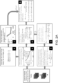
- FIG. 2A shows a flow chart of an embodiment of an LSM processing algorithm.
- Speckle frames are acquired at both parallel and perpendicular polarization states (Box 1).
- Temporal cross-correlation of intensity variations within individual pixels of the frame returns the speckle intensity autocorrelation, g 2 (t), curves at both polarizations (Box 2).
- Calculating the ratio of the log of g 2 (t) curves at the two polarization states yields the ratio of the y coefficients (Box 3).
- Temporal averaging of the speckle frames yields the diffuse reflectance profile (DRP) (Box 4). Comparing the diffuse reflectance with that of a standard reflector yields the ⁇ a/ ⁇ s' ratio (Box 5).
- DRP diffuse reflectance profile
- the mean square displacement (MSD) of local scattering particles is deduced from the g 2 (t) curves (Box 6).
- the ⁇ ⁇ / ⁇ ⁇ is compared with the lookup table to yield the scattering particle size distribution (Box 7).
- GSER Generalized Stokes-Einstein relation
- spatial maps of the frequency-dependent modulus, G(x,y,w) and particle size a(x,y) can be measured to extract indices related to disease processes based on the heterogeneous properties of the sample.
- More rigid elastic medium particles have restricted motion, and displacements around the center of equilibrium is constant.
- MSD may take a more complicated shape.
- the extent and scale of particles' Brownian displacements, quantified by MSD is determined by the rigidity and mechanics of the surrounding medium.
- the generalized stokes-Einstein equation may be used to derive the viscoelastic modulus.
- the same mechanical modulus can be obtained in a non-contact and non-destructive manner.
- the optical properties of tissue including absorption coefficient, ⁇ a , and the reduced scattering coefficient, ⁇ s ', may influence the speckle intensity fluctuations.
- speckle intensity autocorrelation g 2 (t)
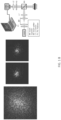
- FIG. 3 displays the speckle frames series acquired by illuminating four tissue specimens, namely adipose, fibrous, and two types of tumor tissue. It has been shown that by averaging the speckle frames over time, one can obtain the diffuse reflectance profile (DRP) of tissue. The radial DRP is then obtained by calculating the average DRP over the points that are at the same distance from the illumination center. Next, a model function derived from diffusion theory may be fitted to the radial DRP to extract the ⁇ a and ⁇ s '.
- DRP diffuse reflectance profile
- the ⁇ a ⁇ s ′ is relatively small ( ⁇ 0.01), suggesting that for this given wavelength, as long as there are no microvasculature in the tissue, it is not critical to evaluate or correct for optical properties. Nevertheless, if the specimen includes microvasculature, this ratio may grow larger, due to absorption from blood. In that case, it is important to estimate and correct for optical properties.
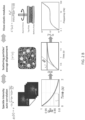
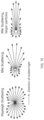
- the next step in evaluating the G( ⁇ ) from MSD is to estimate the average sphere-equivalent radius of scattering particles, a ( FIG. 4 ).
- a the average sphere-equivalent radius of scattering particles
- the speckle patterns shown on the left in FIG. 4 are remitted from adipose, fibrous, and tumors. As can be seen, the patterns are quite similar to one another and are mostly bilobular (elliptical). This indicates that for majority of soft tissues, the particle size is comparable to 100 nm (0.1 ⁇ m), although it is difficult to pinpoint the exact particle size.
- the presently-disclosed methods have been developed to overcome this issue. It was noted that the speckle patterns remitted from a sample at parallel and perpendicular states do not fluctuate at the same rate. In other words, the speckle fluctuations are slower in the parallel polarization state. This is because at this state, the number of single scattered light rays are larger compared to the perpendicular states. As the size of scattering particles is reduced, the scattering becomes more and more isotropic. As such, the number of single scattered rays that retain their initial polarization states increases. Moreover, the rays that scattered multiple times depolarize more rapidly. As a result, the rate of speckle decorrelation at parallel and perpendicular polarizations states varies significantly when particle size is reduced.
- the input to the polarization-sensitive correlation transfer Monte Carlo ray tracing (CT-MCRT) algorithm includes the refractive indices of the particles and the surrounding medium, the particle radius, and the concentration of particles.
- CT-MCRT correlation transfer Monte Carlo ray tracing
- the Stokes vector, S was updated via multiplication with the Mueller matrix.
- the imaging plane of the detector e.g. camera
- the irradiance of light retaining the initial polarization state was calculated using the scalar multiplication of S with S0.
- W i refers to the scalar product of the Stokes vector of the photon with the Stokes vector corresponding to detection polarization. That is, the component of photon intensity that is aligned with the polarization state of the detection polarization state.
- the ⁇ ⁇ ⁇ ⁇ ⁇ ratio is a function of time. It is hypothesized that this ratio is largest at early times, when the contribution of shorter paths is dominant. On the other hand, it will decay at longer times where the contributions from longer paths increases. Therefore, it is likely possible to obtain the particle size distribution by analyzing the ratio as a function of the lag time.
- FIG. 7C shows procedures for obtaining the particle size distribution based on the different relaxation times of the g2(t) curves.
- the g2(t) curve elicited from a poly-dispersed sample exhibits multiple relaxation times corresponding to the size distribution of the scattering particles. Shorter optical paths correspond to small particles and induce the early decorrelation of the g2(t) curves, while longer paths frequently correspond to larger, forwardly directing scattering centers.
- g2(t) curves are obtained by both ensemble averaging of speckle autocorrelation of all the speckle spots within the frame and by temporally averaging multiple curves evolving in time ( FIG. 7A ).
- particle size distribution several other approaches may be possible based on spatio-temporal processing of the speckle frame series and modifying the illumination and collection geometries, as well as the illumination wavelength as detailed herein.
- FIG. 7D shows procedures for obtaining the particle size distribution based on the spatial mapping of the decorrelation ratio.
- Spatio-temporal analysis of speckle fluctuations yields a 2D map of g2(t) curves for individual pixels within the frame.
- illumination and acquiring speckle frame series through an objective lens enables spatial mappings of the speckle dynamics.
- a spatial map of the scattering particle size may be evaluated.
- the spatio-temporal analysis may be further combined to obtain a more detailed map of particle size distributions across the sample.
- the spatio-temporal variations of ⁇ ⁇ ⁇ ⁇ may be interpreted in many different ways, with the spatial variations elucidating the transverse variations in particle size and the temporal variations attributed to the longer paths emerging from deeper sections to obtain a volumetric map of the scattering particle size.
- the illumination and collection polarization states may be varied from being linear to circular and elliptical to eliminate and mitigate the specular reflection.
- FIG. 7E shows procedures for extending the size range by exploiting hyperspectral speckle acquisition.
- the relationship between ⁇ ⁇ ⁇ ⁇ and the scattering particle size is dependent upon the illumination wavelength. This is because the scattering phase function of the particles depends on the a/ ⁇ ratio:
- the illumination wavelength may include 633 nm light and in various other embodiments the illumination wavelength may include light ranging from 400 nm - 1400 nm. Provided that the tissue is not highly absorbing at a particular wavelength, that particular wavelength may be included in the range of illumination wavelengths.
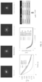
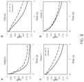
- FIG. 8 panels A-D display the experimentally evaluated g 2 ⁇ (t) and g 2 ⁇ (t) curves for normal adipose and fibrous, as well as tumor tissues.
- Experimentally derived ⁇ ⁇ / ⁇ ⁇ yield the following values for the samples displayed in this figure. These values are consistent with the prior studies on calculating the scattering particle size distribution by scanning electron microscopy (SEM).
- the range of accessible frequencies spans multiple decades and is virtually unlimited.
- the frequency range is determined by the acquisition frame rate and duration.
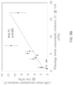
- mechanical testing devices need to evaluate the stress to strain ratio at each frequency, one at a time, to yield the G(w) over a limited frequency range of 0.1-10 Hz, at discrete time points, of for instance 10-20 points per decade.
- the frequency range accessible to LSM extends beyond multiple kHz directly dependent on the speckle image acquisition rate of the detector or camera.
- LSM is also able to deduce both the viscous and elastic components of the complex modulus.
- ⁇ ⁇ ⁇ 0 ⁇ e ⁇ t t ⁇ ⁇ 1 dt t ⁇ u t ⁇ F ⁇ ⁇ + 1 ⁇ ⁇ ⁇ + 1 e ⁇ j ⁇ 2 ⁇ + 1
- FIG. 9A shows frequency-dependent shear viscoelastic modulus, G, evaluated using the LSM for various biological tissues in panel: adipose or fat, typical fibrous tissue, tumor tissue type 1 and tumor tissue type 2.
- FIG. 9B provides a comparison of the disclosed procedures to conventional rheology.
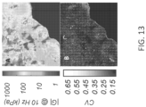
- FIG. 10A shows the spatial map of the shear viscoelastic modulus, G, evaluated using the LSM for a normal fatty tissue at multiple frequencies.
- FIG. 10B shows the spatial map of the shear viscoelastic modulus, G, evaluated using the LSM for a biological tissue at multiple frequencies.
- Tissue heterogeneity in the viscoelastic parameter G and scattering size parameter, a The analysis methods disclosed below demonstrate the capability to extract and quantify tissue heterogeneity in mechanical properties given by the viscoelastic parameter defined by G or G* (also termed viscoelastic modulus or stiffness parameter). Comparable methods are used to similarly quantify heterogeneity in scattering particle size a to estimate indices related to but not limited to average, entropy, dispersion, and fractal dimension, as detailed below. Similarly, heterogeneity metrics may be derived separately for the elastic and viscous parameters, G' and G", respectively (also termed elastic modulus, viscous modulus, stiffness, or viscosity).
- micromechanical indices may be extracted from the G(x,y,w) evaluated by LSM. These include: the average value of the viscoelastic parameter of the biological tissue, G* ave , the maximum modulus value G* max , and the standard deviation of modulus distribution within the tumor ⁇ * G .
- multiple indices of modulus heterogeneity are evaluated as described below and illustrated pictorially below.
- Otsu's method MATLAB image processing toolbox
- the following heterogeneity indices are calculated (see FIG. 11 ):
- Heterogeneity The spatial profile of the shear modulus may be processed to yield the following: the average modulus, G , modulus gradient or slope as well as the modulus heterogeneity indices.
- the G parameter is similar to the metrics evaluated by existing clinical techniques.
- the modulus gradient or slope and heterogeneity indices are uniquely accessible by LSM and highlight the strength of this novel platform in evaluating additional metrics of intra-tumoral mechanical heterogeneities. For example the steepness of the modulus gradient is an example of heterogeneity metrics. Additional examples of the numerous possibilities afforded by the LSM in probing and interpreting the micro-mechanical heterogeneities include:
- the above heterogeneity metrics may also be determined for maps of scattering particle size (a) independent of the mechanical properties:
- a novel optical approach for estimating the average size of scattering particles is a non-invasive, non-contact, all-optical technique that enables estimating both the average size of scattering particles and their size distribution, without manipulating the tissues and biomaterials in their native state. It is potentially applicable for a variety of life science, biotechnology, and clinical medicine applications, for instance for sizing of proteins, antibodies, and biomarkers, as well as diagnosis of a variety of human diseases based on cytological analysis of tissue.
- One example application is identifying cancerous tissue and distinguishing it from benign lesions based on the overall change in the size distribution of normal and malignant cells as well as their nuclei and organelles.
- the disclosed procedures are based on evaluating the laser speckle intensity fluctuations at perpendicular and parallel polarization states to infer the size of scattering particles.
- Speckle is a granular intensity pattern that forms when a coherent laser beam is backscattered from scattering media, such as in tissue. Speckle fluctuations are intimately related to the Brownian displacements of scattering particles, and hence to the viscoelastic properties of the surrounding tissue microenvironment. In addition, speckle fluctuations are also related to the size of scattering particles. For a medium of a given viscoelastic susceptibility, the speckle patterns' fluctuation rate decreases with the increase in the scattering particle size.
- speckle fluctuation rates are also dependent on the polarization state of collected light, with respect to the polarization state of the illumination beam. More specifically, if the sample is illuminated by a linearly polarized laser beam, the parallel-polarized component of the back-scattered speckle often exhibits slower fluctuations compared to the perpendicularly polarized component.
- the parallel polarized component of the speckle fluctuates entails a larger number of short, slowly decorrelating optical paths.
- the speckle intensity autocorrelation curves, g 2 (t) have been simulated at parallel and perpendicular states for media of different scattering particle sizes. For each scattering particles size, the ratio of log(g 2 (t)) was then calculated in parallel and perpendicular polarizations states. This yields a lookup table that enables one to retrieve the average particle size from the rate of speckle fluctuations at the two polarization states.
- Embodiments of the current invention provide apparatus and algorithms for accurate sizing of particles within tissues and biomaterials.
- one or more of the following may be included in the optical apparatus used to acquire the backscattered signal:
- Embodiments of the disclosed techniques enable estimation of the average particle size, as well as the scattering particle size distribution in the biological tissues and biomaterials in their native states, without the need for manipulating the sample.
- destructive techniques such as electron microscopy to assess the size scales of refractive index heterogeneities and mismatch that represent the size scales of scattering particle sizes.
- other optical approaches have been developed that allow for estimating the size distribution in extremely diluted liquid samples. Nevertheless, none of these techniques are applicable to live biological tissues and biomaterials in their native states.
- the approach proposed here enables sizing the scattering particles in both liquid and solid specimens, using non-ionizing light rays, without contacting the specimen or manipulating it in any way.
- a probe to collect light from a sample may be placed near the skin surface of a subject and light may be transmitted through the subject's skin to obtain optical data as disclosed herein.
- the probe may be inserted under the skin (e.g. the probe may be inserted via a small bore needle, endoscope, or other surgical tool) and optical information may be obtained from tissues (e.g. breast tissue) in deep, typically inaccessible tissue or within luminal organs without having to transmit light through the skin itself.
- laser speckle patterns are elicited from endogenous microscopic particles of unknown size distribution and concentration within the tissue. These include the fibers and fibrils composing the extracellular matrices, the cellular membranes, organelles, and nuclei. As such the rate of dynamic laser speckle fluctuations is related to the kinetics of these light scattering particles. Pathogenesis of human disease often simultaneously alters both the size scales of these particles and the mechanical properties of the tissue environment, which together modulate the laser speckle dynamics.
- the current invention proposes an apparatus and algorithm in which the size distribution of these endogenous light scattering centers are calculated by obtaining either of the temporally-resolved or temporally-averaged speckle data, depending on the range of scattering particle sizes, in both micron and submicron ranges, and a polarization-sensitive correlation transfer Monte Carlo ray tracing (PSCT-MCRT) algorithm is implemented to evaluate and decouple the contribution of optical properties and particle size distribution from that of viscoelastic susceptibility of the tissue microenvironment.
- PSCT-MCRT polarization-sensitive correlation transfer Monte Carlo ray tracing
- Embodiments of these procedures may be implemented to apply this approach for estimating the size distribution of proteins, bio-polymers, and biomarkers, and for several in vitro and in vivo diagnostic applications to various basic science as well as clinical applications.
- Embodiments of these procedures may enable particle sizing in tissue specimens to identify neoplastic cells based on skewed scattering particle size distributions.
- This approach has been originally developed to enable estimating the viscoelastic modulus from the speckle fluctuation rate. By isolating the influence of scattering particle size distribution on the speckle signal, this approach allows for quantitative evaluation of the viscoelastic modulus as well.
- the current approach may be commercialized in the form of hand held diagnostic sensors, probes, and imaging devices, as well as bench-top lab microscopes for simultaneous mapping of both tissue granularity and viscoelastic properties with optical resolution, in wide array of basic science and clinical medicine applications.
- the present disclosure provides optical visco-elastography techniques which enable bridging the gap between clinical elastography and research grade, nano-scale indentation.
- Optical elasticity imaging modalities often make certain assumption about physical and mechanical attributes of the tissue, and LSM may quantitatively evaluate the viscoelastic modulus in breast lesions of unknown optical properties and scattering particle size.
- LSM may quantitatively evaluate the viscoelastic modulus in breast lesions of unknown optical properties and scattering particle size.
- combining the newly proposed approach for particle sizing with previous techniques enables particle sizing over an extended range, pertinent to tissues and biomaterials.
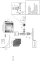
- a computing device 1410 can execute at least a portion of a system for non-destructively estimating an average size of scattering particles in a sample 1404 and provide control signals to one or more optical components associated with a laser speckle microrheology (LSM) system 1402.
- LSM laser speckle microrheology
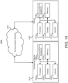
- computing device 1410 can communicate information regarding the control signals to or from a server 1420 over a communication network 1406, which can execute at least a portion of system for non-destructively estimating an average size of scattering particles in a sample 1404.
- server 1420 can return information to computing device 1410 (and/or any other suitable computing device) relating to the control signals for system for non-destructively estimating an average size of scattering particles in a sample 1404. This information may be transmitted and/or presented to a user (e.g. a researcher, an operator, a clinician, etc.) and/or may be stored (e.g. as part of a research database or a medical record associated with a subject).
- computing device 1410 and/or server 1420 can be any suitable computing device or combination of devices, such as a desktop computer, a laptop computer, a smartphone, a tablet computer, a wearable computer, a server computer, a virtual machine being executed by a physical computing device, etc.
- system for non-destructively estimating an average size of scattering particles in a sample 1404 can present information about the control signals to a user (e.g., researcher and/or physician).
- LSM system 1402 may include optical components such as those disclosed herein (e.g. see FIG. 1A ).
- communication network 1406 can be any suitable communication network or combination of communication networks.
- communication network 1406 can include a Wi-Fi network (which can include one or more wireless routers, one or more switches, etc.), a peer-to-peer network (e.g., a Bluetooth network), a cellular network (e.g., a 3G network, a 4G network, a 5G network, etc., complying with any suitable standard, such as CDMA, GSM, LTE, LTE Advanced, WiMAX, etc.), a wired network, etc.
- Wi-Fi network which can include one or more wireless routers, one or more switches, etc.
- peer-to-peer network e.g., a Bluetooth network
- a cellular network e.g., a 3G network, a 4G network, a 5G network, etc., complying with any suitable standard, such as CDMA, GSM, LTE, LTE Advanced, WiMAX, etc.
- a wired network etc.
- FIG. 15 shows an example 1500 of hardware that can be used to implement computing device 1410 and server 1420 in accordance with some embodiments of the disclosed subject matter.
- computing device 1410 can include a processor 1502, a display 1504, one or more inputs 1506, one or more communication systems 1508, and/or memory 1510.
- processor 1502 can be any suitable hardware processor or combination of processors, such as a central processing unit, a graphics processing unit, etc.
- display 1504 can include any suitable display devices, such as a computer monitor, a touchscreen, a television, etc.
- inputs 1506 can include any suitable input devices and/or sensors that can be used to receive user input, such as a keyboard, a mouse, a touchscreen, a microphone, etc.
- communications systems 1508 can include any suitable hardware, firmware, and/or software for communicating information over communication network 1406 and/or any other suitable communication networks.
- communications systems 1508 can include one or more transceivers, one or more communication chips and/or chip sets, etc.
- communications systems 1508 can include hardware, firmware and/or software that can be used to establish a Wi-Fi connection, a Bluetooth connection, a cellular connection, an Ethernet connection, etc.
- server 1420 can include a processor 1512, a display 1514, one or more inputs 1516, one or more communications systems 1518, and/or memory 1520.
- processor 1512 can be any suitable hardware processor or combination of processors, such as a central processing unit, a graphics processing unit, etc.
- display 1514 can include any suitable display devices, such as a computer monitor, a touchscreen, a television, etc.
- inputs 1516 can include any suitable input devices and/or sensors that can be used to receive user input, such as a keyboard, a mouse, a touchscreen, a microphone, etc.
- communications systems 1518 can include any suitable hardware, firmware, and/or software for communicating information over communication network 1406 and/or any other suitable communication networks.
- communications systems 1518 can include one or more transceivers, one or more communication chips and/or chip sets, etc.
- communications systems 1518 can include hardware, firmware and/or software that can be used to establish a Wi-Fi connection, a Bluetooth connection, a cellular connection, an Ethernet connection, etc.
- memory 1520 can include any suitable storage device or devices that can be used to store instructions, values, etc., that can be used, for example, by processor 1512 to present content using display 1514, to communicate with one or more computing devices 1410, etc.
- Memory 1520 can include any suitable volatile memory, non-volatile memory, storage, or any suitable combination thereof.
- memory 1520 can include RAM, ROM, EEPROM, one or more flash drives, one or more hard disks, one or more solid state drives, one or more optical drives, etc.
- memory 1520 can have encoded thereon a server program for controlling operation of server 1420.
- any suitable computer readable media can be used for storing instructions for performing the functions and/or processes described herein.
- computer readable media can be transitory or non-transitory.
- non-transitory computer readable media can include media such as magnetic media (such as hard disks, floppy disks, etc.), optical media (such as compact discs, digital video discs, Blu-ray discs, etc.), semiconductor media (such as RAM, Flash memory, electrically programmable read only memory (EPROM), electrically erasable programmable read only memory (EEPROM), etc.), any suitable media that is not fleeting or devoid of any semblance of permanence during transmission, and/or any suitable tangible media.
- magnetic media such as hard disks, floppy disks, etc.
- optical media such as compact discs, digital video discs, Blu-ray discs, etc.
- semiconductor media such as RAM, Flash memory, electrically programmable read only memory (EPROM), electrically erasable programmable read only memory (EEPROM), etc.
- transitory computer readable media can include signals on networks, in wires, conductors, optical fibers, circuits, or any suitable media that is fleeting and devoid of any semblance of permanence during transmission, and/or any suitable intangible media.
- mechanism can encompass hardware, software, firmware, or any suitable combination thereof.
- FIG. 16 shows an example 1600 of a process for non-destructively estimating an average size of scattering particles in a sample in accordance with some embodiments of the disclosed subject matter.
- process 1600 can transmit polarized light to the sample.
- the polarized light may be transmitted using a coherent light source such as a laser.
- process 1600 can obtain polarized light reflected from the sample.
- the polarized light may include a parallel polarized component and a perpendicular polarized component.
- Obtaining polarized light reflected from the sample may be performed using a detector such as a camera.
- process 1600 can determine speckle decorrelation rates for the parallel polarized component and the perpendicular polarized component.
- Determining speckle decorrelation rates may be performed using a processor such as a computer processor.
- process 1200 can estimate the average size of scattering particles in the sample based on the speckle decorrelation rates for the parallel polarized component and the perpendicular polarized component. Estimating the average size of scattering particles can be performed using the processor.
Landscapes
- Chemical & Material Sciences (AREA)
- Physics & Mathematics (AREA)
- Health & Medical Sciences (AREA)
- Life Sciences & Earth Sciences (AREA)
- Analytical Chemistry (AREA)
- Biochemistry (AREA)
- General Health & Medical Sciences (AREA)
- General Physics & Mathematics (AREA)
- Immunology (AREA)
- Pathology (AREA)
- Dispersion Chemistry (AREA)
- Investigating Or Analysing Materials By Optical Means (AREA)
Claims (16)
- Verfahren zur zerstörungsfreien Schätzung der durchschnittlichen Größe von streuenden Partikeln in einer Probe, umfassend:Übertragen von polarisiertem Licht mit einer kohärenten Lichtquelle auf die Probe;Erfassen von polarisiertem Licht, das von der Probe reflektiert wird, unter Verwendung eines Detektors, der konfiguriert ist, das polarisierte Licht über die Zeit zu erfassen, um eine parallel polarisierte Komponente und eine senkrecht polarisierte Komponente zu erfassen;Erzeugen von Speckle-Bildern unter Verwendung des vom Detektor erfassten polarisierten Lichts;Bestimmen, unter Verwendung eines Prozessors und der Speckle-Bilder, der Speckle-Dekorrelationsraten für die parallel polarisierte Komponente und die senkrecht polarisierte Komponente; undSchätzen der durchschnittlichen Größe der streuenden Partikel in der Probe unter Verwendung des Prozessors auf der Grundlage der Speckle-Dekorrelationsraten für die parallel polarisierte Komponente und die senkrecht polarisierte Komponente.
- Verfahren nach Anspruch 1, wobei der Detektor eine Vielzahl von Pixeln aufweist, die einer Vielzahl von räumlich verteilten Orten innerhalb der Probe entsprechen, undwobei das Erfassen von polarisiertem Licht, das von der Probe reflektiert wird, umfasst:
Erfassen von polarisiertem Licht, das von der Probe durch die Vielzahl von Pixeln reflektiert wird,wobei das Bestimmen der Speckle-Dekorrelationsraten für die parallel polarisierte Komponente und die senkrecht polarisierte Komponente umfasst:
Bestimmen von Speckle-Dekorrelationsraten für die parallel polarisierte Komponente und die senkrecht polarisierte Komponente für jedes der Vielzahl von Pixeln, undwobei das Schätzen der durchschnittlichen Größe der streuenden Partikel in der Probe umfasst:
Schätzen der durchschnittlichen Größe der streuenden Partikel für jedes der Vielzahl von Pixeln, die jeder der Vielzahl von räumlich verteilten Orten innerhalb der Probe entsprechen. - Verfahren nach Anspruch 1, wobei das Erfassen von polarisiertem Licht, das von der Probe reflektiert wird, umfasst:
Erfassen von polarisiertem Licht, das von der Probe als Funktion der Zeit reflektiert wird; und
wobei das Bestimmen der Speckle-Dekorrelationsraten für die parallel polarisierte Komponente und die senkrecht polarisierte Komponente umfasst:
Bestimmen der Speckle-Dekorrelationsraten für die parallel polarisierte Komponente und die senkrecht polarisierte Komponente auf der Grundlage des von der Probe reflektierten polarisierten Lichts als Funktion der Zeit. - Verfahren nach Anspruch 3, wobei das Bestimmen der Speckle-Dekorrelationsraten für die parallel polarisierte Komponente und die senkrecht polarisierte Komponente auf der Grundlage des von der Probe reflektierten polarisierten Lichts als Funktion der Zeit umfasst:
Bestimmen von Speckle-Dekorrelationsraten auf der Grundlage des Bestimmens von Relaxationskurven für die parallel polarisierte Komponente und die senkrecht polarisierte Komponente des von der Probe reflektierten polarisierten Lichts als Funktion der Zeit; und
wobei das Schätzen der durchschnittlichen Größe der streuenden Partikel in der Probe auf der Grundlage der Speckle-Dekorrelationsraten für die parallel polarisierte Komponente und die senkrecht polarisierte Komponente umfasst:
Schätzen der durchschnittlichen Größe der streuenden Partikel in der Probe auf der Grundlage der Speckle-Dekorrelationsraten für die parallel polarisierte Komponente und die senkrecht polarisierte Komponente auf der Grundlage der Relaxationskurven für die parallel polarisierte Komponente und die senkrecht polarisierte Komponente des von der Probe reflektierten polarisierten Lichts als Funktion der Zeit. - Verfahren nach Anspruch 1, wobei das Bestimmen der Speckle-Dekorrelationsraten für die parallel polarisierte Komponente und die senkrecht polarisierte Komponente umfasst:
Bestimmen der Speckle-Dekorrelationsraten für die parallel polarisierte Komponente und die senkrecht polarisierte Komponente auf der Grundlage einer Wertetabelle. - Verfahren nach Anspruch 1 ferner umfassend das Übertragen von linear polarisiertem Licht auf die Probe durch:
Übertragen von linear polarisiertem Licht mit einer Vielzahl von Wellenlängen auf die Probe; und
wobei das Schätzen der durchschnittlichen Größe der streuenden Partikel in der Probe umfasst:
Schätzen der durchschnittlichen Größe der streuenden Partikel in der Probe auf der Grundlage des Übertragens von linear polarisiertem Licht, das eine Vielzahl von Wellenlängen aufweist, auf die Probe. - Verfahren nach Anspruch 1, wobei das Übertragen von linear polarisiertem Licht auf die Probe umfasst:
abwechselnd Übertragen von parallel und senkrecht polarisiertem Licht auf die Probe. - Verfahren nach Anspruch 7, wobei das abwechselnd Übertragen von parallel und senkrecht polarisiertem Licht auf die Probe umfasst:
Modulation zwischen parallel polarisiertem Licht und senkrecht polarisiertem Licht unter Verwendung eines Polarisationsmodulators, gegebenenfalls in Kombination mit einem optischen Isolator oder Polarisationsisolator auf der Grundlage von Umschaltspiegeln, um entweder das parallel polarisierte Licht oder das senkrecht polarisierte Licht auszuwählen. - Vorrichtung zur zerstörungsfreien Schätzung der durchschnittlichen Größe von streuenden Partikeln in einer Probe, aufweisend:eine kohärente Lichtquelle;einen Detektor; undeinen Prozessor, der mit der kohärenten Lichtquelle und dem Detektor in Verbindung steht, wobei der Prozessor konfiguriert ist zum:Steuern der kohärenten Lichtquelle, um polarisiertes Licht auf die Probe zu übertragen,Steuern des Detektors, um das von der Probe reflektierte Licht als polarisiertes Licht mit einer parallel polarisierten Komponente und einer senkrecht polarisierten Komponente zu erfassen,Erzeugen von Speckle-Bildern mit dem vom Detektor erfassten polarisierten Licht;Verwenden der Speckle-Bilder zur Bestimmung der Speckle-Dekorrelationsraten für die parallel polarisierte Komponente und die senkrecht polarisierte Komponente, undSchätzen der durchschnittlichen Größe der streuenden Partikel in der Probe auf der Grundlage der Speckle-Dekorrelationsraten für die parallel polarisierte Komponente und die senkrecht polarisierte Komponente.
- Vorrichtung nach Anspruch 9, wobei der Detektor eine Vielzahl von Pixeln aufweist, die einer Vielzahl von räumlich verteilten Orten innerhalb der Probe entsprechen, undwobei der Prozessor beim Erhalten von polarisiertem Licht, das von der Probe reflektiert wird, weiterhin konfiguriert ist, zum:
Erfassen von polarisiertem Licht, das von der Probe über die Vielzahl von Pixeln reflektiert wird,wobei der Prozessor beim Bestimmen von Speckle-Dekorrelationsraten für die parallel polarisierte Komponente und die senkrecht polarisierte Komponente ferner konfiguriert ist zum:
Bestimmen von Speckle-Dekorrelationsraten für die parallel polarisierte Komponente und die senkrecht polarisierte Komponente für jedes der Vielzahl von Pixeln, undwobei der Prozessor beim Schätzen der durchschnittlichen Größe der streuenden Partikel in der Probe weiterhin konfiguriert ist zum:
Schätzen der durchschnittlichen Größe von streuenden Partikeln für jedes der Vielzahl von Pixeln, die jedem der Vielzahl von räumlich verteilten Orten innerhalb der Probe entsprechen. - Vorrichtung nach Anspruch 9, wobei der Prozessor, beim Erfassen von polarisiertem Licht, das von der Probe reflektiert wird ferner konfiguriert ist zum:
Erfassen von polarisiertem Licht, das von der Probe reflektiert wird, als Funktion der Zeit; und
wobei der Prozessor beim Bestimmen von Speckle-Dekorrelationsraten für die parallel polarisierte Komponente und die senkrecht polarisierte Komponente ferner konfiguriert ist zum:
Bestimmen der Speckle-Dekorrelationsraten für die parallel polarisierte Komponente und die senkrecht polarisierte Komponente auf der Grundlage des von der Probe reflektierten polarisierten Lichts als Funktion der Zeit. - Vorrichtung nach Anspruch 11, wobei der Prozessor bei der Bestimmung der Speckle-Dekorrelationsraten für die parallel polarisierte Komponente und die senkrecht polarisierte Komponente auf der Grundlage des von der Probe reflektierten polarisierten Lichts als Funktion der Zeit ferner konfiguriert ist zum:
Bestimmen von Speckle-Dekorrelationsraten auf der Grundlage des Bestimmens von Relaxationskurven für die parallel polarisierte Komponente und die senkrecht polarisierte Komponente des von der Probe reflektierten polarisierten Lichts als Funktion der Zeit; und
wobei der Prozessor beim Schätzen der durchschnittlichen Größe der streuenden Partikel in der Probe auf der Grundlage der Speckle-Dekorrelationsraten für die parallel polarisierte Komponente und die senkrecht polarisierte Komponente ferner konfiguriert ist zum:
Schätzen der durchschnittlichen Größe der streuenden Partikel in der Probe auf der Grundlage der Speckle-Dekorrelationsraten für die parallel polarisierte Komponente und die senkrecht polarisierte Komponente auf der Grundlage der Relaxationskurven für die parallel polarisierte Komponente und die senkrecht polarisierte Komponente des von der Probe reflektierten polarisierten Lichts als Funktion der Zeit. - Vorrichtung nach Anspruch 12, wobei der Prozessor beim Schätzen der durchschnittlichen Größe der streuenden Partikel in der Probe auf der Grundlage der Speckle-Dekorrelationsraten für die parallel polarisierte Komponente und die senkrecht polarisierte Komponente ferner konfiguriert zum:
Schätzen der durchschnittlichen Größe der streuenden Partikel in der Probe auf der Grundlage der Bestimmung eines Verhältnisses der Relaxationskurven für die parallel polarisierte Komponente und die senkrecht polarisierte Komponente des von der Probe reflektierten polarisierten Lichts als Funktion der Zeit. - Vorrichtung nach Anspruch 9, wobei der Prozessor beim Bestimmen der Speckle-Dekorrelationsraten für die parallel polarisierte Komponente und die senkrecht polarisierte Komponente ferner konfiguriert ist zum:
Bestimmen der Speckle-Dekorrelationsraten für die parallel polarisierte Komponente und die senkrecht polarisierte Komponente auf der Grundlage einer Wertetabelle. - Vorrichtung nach Anspruch 9, wobei der Prozessor beim Übertragen von polarisiertem Licht auf die Probe ferner konfiguriert ist zum:(1) Übertragen von polarisiertem Licht, das eine Vielzahl von Wellenlängen aufweist, zu der Probe, und wobei der Prozessor, beim Schätzen der durchschnittlichen Größe von streuenden Partikeln in der Probe ferner konfiguriert ist zum Schätzen der durchschnittlichen Größe von streuenden Partikeln in der Probe auf der Grundlage des Übertragens von polarisiertem Licht, das eine Vielzahl von Wellenlängen aufweist, zu der Probe; oder(2) abwechselnd Übertragen von parallel und senkrecht polarisiertem Licht auf die Probe.
- Vorrichtung nach Anspruch 15, wobei der Prozessor beim (2) abwechselnd Übertragen von parallel polarisiertem Licht und senkrecht polarisiertem Licht auf die Probe ferner konfiguriert ist zum:
Modulieren zwischen parallel polarisiertem Licht und senkrecht polarisiertem Licht, wobei ein Polarisationsmodulator verwendet wird, der optional mit einem optischen Isolator oder einem Polarisationsisolator auf der Grundlage von Umschaltspiegeln kombiniert werden kann, um entweder das parallel polarisierte Licht oder das senkrecht polarisierte Licht auszuwählen.
Applications Claiming Priority (2)
| Application Number | Priority Date | Filing Date | Title |
|---|---|---|---|
| US202062968308P | 2020-01-31 | 2020-01-31 | |
| PCT/US2021/016066 WO2021155361A1 (en) | 2020-01-31 | 2021-02-01 | Methods and systems for non-destructive estimation of scattering particle size |
Publications (3)
| Publication Number | Publication Date |
|---|---|
| EP4097445A1 EP4097445A1 (de) | 2022-12-07 |
| EP4097445A4 EP4097445A4 (de) | 2024-02-28 |
| EP4097445B1 true EP4097445B1 (de) | 2025-04-16 |
Family
ID=77078479
Family Applications (1)
| Application Number | Title | Priority Date | Filing Date |
|---|---|---|---|
| EP21747699.3A Active EP4097445B1 (de) | 2020-01-31 | 2021-02-01 | Verfahren und systeme zur zerstörungsfreien schätzung der grösse von streuenden teilchen |
Country Status (4)
| Country | Link |
|---|---|
| US (1) | US12366512B2 (de) |
| EP (1) | EP4097445B1 (de) |
| JP (1) | JP7559072B2 (de) |
| WO (1) | WO2021155361A1 (de) |
Families Citing this family (5)
| Publication number | Priority date | Publication date | Assignee | Title |
|---|---|---|---|---|
| US20250334504A1 (en) * | 2022-06-14 | 2025-10-30 | Sony Group Corporation | Particle sorting system, particle sorting method, and particle sorting program |
| EP4306928A1 (de) * | 2022-07-15 | 2024-01-17 | Sympatec GmbH | Dynamisches 3d-lichtstreuungs-partikelgrössenverteilungsmessgerät und verfahren zum bestimmen einer partikelgrössenverteilung |
| WO2024159227A2 (en) * | 2023-01-27 | 2024-08-02 | The General Hospital Corporation | Systems and methods for measuring particle size in tissue and turbid media |
| WO2025018100A1 (ja) * | 2023-07-14 | 2025-01-23 | 富士フイルム株式会社 | 光測定方法、及び光測定装置 |
| CN120820958B (zh) * | 2025-09-19 | 2025-11-28 | 南京理工大学 | 基于偏振编码和空间复用的多场景单帧大视场散射成像方法 |
Family Cites Families (8)
| Publication number | Priority date | Publication date | Assignee | Title |
|---|---|---|---|---|
| US6100976A (en) * | 1998-09-21 | 2000-08-08 | The Board Of Regents For Oklahoma State University | Method and apparatus for fiber optic multiple scattering suppression |
| US6639674B2 (en) * | 2000-03-28 | 2003-10-28 | Board Of Regents, The University Of Texas System | Methods and apparatus for polarized reflectance spectroscopy |
| DE102009014080B4 (de) | 2009-03-23 | 2011-12-15 | Baumer Innotec Ag | Vorrichtung zum Bestimmen von Partikelgrössen |
| US10359361B2 (en) * | 2011-02-18 | 2019-07-23 | The General Hospital Corporation | Laser speckle micro-rheology in characterization of biomechanical properties of tissues |
| WO2014043609A1 (en) | 2012-09-17 | 2014-03-20 | The General Hospital Corporation | Compensation for causes of temporal fluctuations of backscattered speckle patterns in laser speckle rheology of biological fluids |
| EP4235151B1 (de) * | 2014-01-31 | 2025-08-27 | The General Hospital Corporation | System und verfahren zur schätzung der mechanischen eigenschaften und der grösse von lichtstreuenden partikeln in materialien |
| US11150173B2 (en) * | 2016-02-12 | 2021-10-19 | The General Hospital Corporation | Laser speckle micro-rheology in characterization of biomechanical properties of tissues |
| US11328185B2 (en) * | 2017-06-30 | 2022-05-10 | California Institute Of Technology | Noninvasive, label-free, in vivo flow cytometry using speckle correlation technique |
-
2021
- 2021-02-01 WO PCT/US2021/016066 patent/WO2021155361A1/en not_active Ceased
- 2021-02-01 JP JP2022546655A patent/JP7559072B2/ja active Active
- 2021-02-01 EP EP21747699.3A patent/EP4097445B1/de active Active
- 2021-02-01 US US17/759,738 patent/US12366512B2/en active Active
Also Published As
| Publication number | Publication date |
|---|---|
| EP4097445A4 (de) | 2024-02-28 |
| WO2021155361A1 (en) | 2021-08-05 |
| US12366512B2 (en) | 2025-07-22 |
| JP7559072B2 (ja) | 2024-10-01 |
| JP2023513471A (ja) | 2023-03-31 |
| EP4097445A1 (de) | 2022-12-07 |
| US20230083866A1 (en) | 2023-03-16 |
Similar Documents
| Publication | Publication Date | Title |
|---|---|---|
| EP4097445B1 (de) | Verfahren und systeme zur zerstörungsfreien schätzung der grösse von streuenden teilchen | |
| Kennedy et al. | The emergence of optical elastography in biomedicine | |
| Pitre Jr et al. | Nearly-incompressible transverse isotropy (NITI) of cornea elasticity: model and experiments with acoustic micro-tapping OCE | |
| Kim et al. | Holotomography | |
| Prevedel et al. | Brillouin microscopy: an emerging tool for mechanobiology | |
| Ushenko et al. | 3D Mueller matrix mapping of layered distributions of depolarisation degree for analysis of prostate adenoma and carcinoma diffuse tissues | |
| Dalimier et al. | Full-field optical coherence tomography: a new technology for 3D high-resolution skin imaging | |
| Tilbury et al. | Second harmonic generation microscopy analysis of extracellular matrix changes in human idiopathic pulmonary fibrosis | |
| Monnier et al. | In vivo characterization of healthy human skin with a novel, non‐invasive imaging technique: line‐field confocal optical coherence tomography | |
| Boone et al. | High‐definition optical coherence tomography enables visualization of individual cells in healthy skin: comparison to reflectance confocal microscopy | |
| Fitzgerald et al. | Classification of terahertz-pulsed imaging data from excised breast tissue | |
| EP2676123B1 (de) | Verfahren zur messung der mechanischen eigenschaften eines biologischen gewebes durch eine laser-speckle interferometrische messung | |
| JP5887006B2 (ja) | 角度分解型のフーリエドメイン光干渉断層撮影法を遂行する方法及びシステム | |
| Napoli et al. | Post-mortem corneal thickness measurements with a portable optical coherence tomography system: a reliability study | |
| Brachtel et al. | Spectrally encoded confocal microscopy for diagnosing breast cancer in excision and margin specimens | |
| WO2021207118A1 (en) | System and method of dynamic micro-optical coherence tomography for mapping cellular functions | |
| Gataric et al. | Reconstruction of optical vector-fields with applications in endoscopic imaging | |
| Lee et al. | An optomechanogram for assessment of the structural and mechanical properties of tissues | |
| Stier et al. | Imaging sub-diffuse optical properties of cancerous and normal skin tissue using machine learning-aided spatial frequency domain imaging | |
| Zhang et al. | Angular range, sampling and noise considerations for inverse light scattering analysis of nuclear morphology | |
| Kazaili et al. | Line-Field Optical Coherence Tomography as a tool for In vitro characterization of corneal biomechanics under physiological pressures | |
| Gao | Fourier spectrum analysis of full-field optical coherence tomography for tissue imaging | |
| Das et al. | Nanoscale structure detection and monitoring of tumour growth with optical coherence tomography | |
| Bartek et al. | Estimation of subcellular particle size histograms<? xpp qa?> with electron microscopy for prediction of optical scattering in breast tissue | |
| Hajjarian et al. | Technological perspectives on laser speckle micro-rheology for cancer mechanobiology research |
Legal Events
| Date | Code | Title | Description |
|---|---|---|---|
| STAA | Information on the status of an ep patent application or granted ep patent |
Free format text: STATUS: THE INTERNATIONAL PUBLICATION HAS BEEN MADE |
|
| PUAI | Public reference made under article 153(3) epc to a published international application that has entered the european phase |
Free format text: ORIGINAL CODE: 0009012 |
|
| STAA | Information on the status of an ep patent application or granted ep patent |
Free format text: STATUS: REQUEST FOR EXAMINATION WAS MADE |
|
| 17P | Request for examination filed |
Effective date: 20220803 |
|
| AK | Designated contracting states |
Kind code of ref document: A1 Designated state(s): AL AT BE BG CH CY CZ DE DK EE ES FI FR GB GR HR HU IE IS IT LI LT LU LV MC MK MT NL NO PL PT RO RS SE SI SK SM TR |
|
| DAV | Request for validation of the european patent (deleted) | ||
| DAX | Request for extension of the european patent (deleted) | ||
| P01 | Opt-out of the competence of the unified patent court (upc) registered |
Effective date: 20230526 |
|
| REG | Reference to a national code |
Ref country code: DE Ref legal event code: R079 Free format text: PREVIOUS MAIN CLASS: G01N0011020000 Ipc: G01N0021470000 Ref document number: 602021029260 Country of ref document: DE |
|
| A4 | Supplementary search report drawn up and despatched |
Effective date: 20240130 |
|
| RIC1 | Information provided on ipc code assigned before grant |
Ipc: G01N 15/0205 20240101ALI20240124BHEP Ipc: G01N 11/16 20060101ALI20240124BHEP Ipc: G01N 15/14 20060101ALI20240124BHEP Ipc: G01N 15/1434 20240101ALI20240124BHEP Ipc: G01N 15/0227 20240101ALI20240124BHEP Ipc: G01N 11/00 20060101ALI20240124BHEP Ipc: G01N 21/47 20060101AFI20240124BHEP |
|
| GRAP | Despatch of communication of intention to grant a patent |
Free format text: ORIGINAL CODE: EPIDOSNIGR1 |
|
| STAA | Information on the status of an ep patent application or granted ep patent |
Free format text: STATUS: GRANT OF PATENT IS INTENDED |
|
| RIC1 | Information provided on ipc code assigned before grant |
Ipc: G01N 15/0205 20240101ALI20241025BHEP Ipc: G01N 11/16 20060101ALI20241025BHEP Ipc: G01N 15/14 20060101ALI20241025BHEP Ipc: G01N 15/1434 20240101ALI20241025BHEP Ipc: G01N 15/0227 20240101ALI20241025BHEP Ipc: G01N 11/00 20060101ALI20241025BHEP Ipc: G01N 21/47 20060101AFI20241025BHEP |
|
| INTG | Intention to grant announced |
Effective date: 20241111 |
|
| GRAS | Grant fee paid |
Free format text: ORIGINAL CODE: EPIDOSNIGR3 |
|
| GRAA | (expected) grant |
Free format text: ORIGINAL CODE: 0009210 |
|
| STAA | Information on the status of an ep patent application or granted ep patent |
Free format text: STATUS: THE PATENT HAS BEEN GRANTED |
|
| AK | Designated contracting states |
Kind code of ref document: B1 Designated state(s): AL AT BE BG CH CY CZ DE DK EE ES FI FR GB GR HR HU IE IS IT LI LT LU LV MC MK MT NL NO PL PT RO RS SE SI SK SM TR |
|
| REG | Reference to a national code |
Ref country code: GB Ref legal event code: FG4D |
|
| REG | Reference to a national code |
Ref country code: CH Ref legal event code: EP Ref country code: DE Ref legal event code: R096 Ref document number: 602021029260 Country of ref document: DE |
|
| REG | Reference to a national code |
Ref country code: IE Ref legal event code: FG4D |
|
| REG | Reference to a national code |
Ref country code: NL Ref legal event code: MP Effective date: 20250416 |
|
| PG25 | Lapsed in a contracting state [announced via postgrant information from national office to epo] |
Ref country code: NL Free format text: LAPSE BECAUSE OF FAILURE TO SUBMIT A TRANSLATION OF THE DESCRIPTION OR TO PAY THE FEE WITHIN THE PRESCRIBED TIME-LIMIT Effective date: 20250416 |
|
| REG | Reference to a national code |
Ref country code: AT Ref legal event code: MK05 Ref document number: 1786004 Country of ref document: AT Kind code of ref document: T Effective date: 20250416 |
|
| PG25 | Lapsed in a contracting state [announced via postgrant information from national office to epo] |
Ref country code: FI Free format text: LAPSE BECAUSE OF FAILURE TO SUBMIT A TRANSLATION OF THE DESCRIPTION OR TO PAY THE FEE WITHIN THE PRESCRIBED TIME-LIMIT Effective date: 20250416 Ref country code: PT Free format text: LAPSE BECAUSE OF FAILURE TO SUBMIT A TRANSLATION OF THE DESCRIPTION OR TO PAY THE FEE WITHIN THE PRESCRIBED TIME-LIMIT Effective date: 20250818 Ref country code: ES Free format text: LAPSE BECAUSE OF FAILURE TO SUBMIT A TRANSLATION OF THE DESCRIPTION OR TO PAY THE FEE WITHIN THE PRESCRIBED TIME-LIMIT Effective date: 20250416 |
|
| REG | Reference to a national code |
Ref country code: LT Ref legal event code: MG9D |
|
| PG25 | Lapsed in a contracting state [announced via postgrant information from national office to epo] |
Ref country code: GR Free format text: LAPSE BECAUSE OF FAILURE TO SUBMIT A TRANSLATION OF THE DESCRIPTION OR TO PAY THE FEE WITHIN THE PRESCRIBED TIME-LIMIT Effective date: 20250717 Ref country code: NO Free format text: LAPSE BECAUSE OF FAILURE TO SUBMIT A TRANSLATION OF THE DESCRIPTION OR TO PAY THE FEE WITHIN THE PRESCRIBED TIME-LIMIT Effective date: 20250716 |
|
| PG25 | Lapsed in a contracting state [announced via postgrant information from national office to epo] |
Ref country code: PL Free format text: LAPSE BECAUSE OF FAILURE TO SUBMIT A TRANSLATION OF THE DESCRIPTION OR TO PAY THE FEE WITHIN THE PRESCRIBED TIME-LIMIT Effective date: 20250416 |
|
| PG25 | Lapsed in a contracting state [announced via postgrant information from national office to epo] |
Ref country code: BG Free format text: LAPSE BECAUSE OF FAILURE TO SUBMIT A TRANSLATION OF THE DESCRIPTION OR TO PAY THE FEE WITHIN THE PRESCRIBED TIME-LIMIT Effective date: 20250416 |
|
| PG25 | Lapsed in a contracting state [announced via postgrant information from national office to epo] |
Ref country code: HR Free format text: LAPSE BECAUSE OF FAILURE TO SUBMIT A TRANSLATION OF THE DESCRIPTION OR TO PAY THE FEE WITHIN THE PRESCRIBED TIME-LIMIT Effective date: 20250416 |
|
| PG25 | Lapsed in a contracting state [announced via postgrant information from national office to epo] |
Ref country code: AT Free format text: LAPSE BECAUSE OF FAILURE TO SUBMIT A TRANSLATION OF THE DESCRIPTION OR TO PAY THE FEE WITHIN THE PRESCRIBED TIME-LIMIT Effective date: 20250416 |
|
| PG25 | Lapsed in a contracting state [announced via postgrant information from national office to epo] |
Ref country code: RS Free format text: LAPSE BECAUSE OF FAILURE TO SUBMIT A TRANSLATION OF THE DESCRIPTION OR TO PAY THE FEE WITHIN THE PRESCRIBED TIME-LIMIT Effective date: 20250716 |
|
| PG25 | Lapsed in a contracting state [announced via postgrant information from national office to epo] |
Ref country code: IS Free format text: LAPSE BECAUSE OF FAILURE TO SUBMIT A TRANSLATION OF THE DESCRIPTION OR TO PAY THE FEE WITHIN THE PRESCRIBED TIME-LIMIT Effective date: 20250816 |
|
| PG25 | Lapsed in a contracting state [announced via postgrant information from national office to epo] |
Ref country code: LV Free format text: LAPSE BECAUSE OF FAILURE TO SUBMIT A TRANSLATION OF THE DESCRIPTION OR TO PAY THE FEE WITHIN THE PRESCRIBED TIME-LIMIT Effective date: 20250416 |