EP4097368B1 - Lagergehäusekonstruktion - Google Patents
Lagergehäusekonstruktion Download PDFInfo
- Publication number
- EP4097368B1 EP4097368B1 EP21702453.8A EP21702453A EP4097368B1 EP 4097368 B1 EP4097368 B1 EP 4097368B1 EP 21702453 A EP21702453 A EP 21702453A EP 4097368 B1 EP4097368 B1 EP 4097368B1
- Authority
- EP
- European Patent Office
- Prior art keywords
- bearing house
- bearing
- feet
- house
- base
- Prior art date
- Legal status (The legal status is an assumption and is not a legal conclusion. Google has not performed a legal analysis and makes no representation as to the accuracy of the status listed.)
- Active
Links
Images
Classifications
-
- F—MECHANICAL ENGINEERING; LIGHTING; HEATING; WEAPONS; BLASTING
- F16—ENGINEERING ELEMENTS AND UNITS; GENERAL MEASURES FOR PRODUCING AND MAINTAINING EFFECTIVE FUNCTIONING OF MACHINES OR INSTALLATIONS; THERMAL INSULATION IN GENERAL
- F16C—SHAFTS; FLEXIBLE SHAFTS; ELEMENTS OR CRANKSHAFT MECHANISMS; ROTARY BODIES OTHER THAN GEARING ELEMENTS; BEARINGS
- F16C35/00—Rigid support of bearing units; Housings, e.g. caps, covers
- F16C35/02—Rigid support of bearing units; Housings, e.g. caps, covers in the case of sliding-contact bearings
-
- F—MECHANICAL ENGINEERING; LIGHTING; HEATING; WEAPONS; BLASTING
- F16—ENGINEERING ELEMENTS AND UNITS; GENERAL MEASURES FOR PRODUCING AND MAINTAINING EFFECTIVE FUNCTIONING OF MACHINES OR INSTALLATIONS; THERMAL INSULATION IN GENERAL
- F16C—SHAFTS; FLEXIBLE SHAFTS; ELEMENTS OR CRANKSHAFT MECHANISMS; ROTARY BODIES OTHER THAN GEARING ELEMENTS; BEARINGS
- F16C35/00—Rigid support of bearing units; Housings, e.g. caps, covers
- F16C35/04—Rigid support of bearing units; Housings, e.g. caps, covers in the case of ball or roller bearings
- F16C35/042—Housings for rolling element bearings for rotary movement
-
- F—MECHANICAL ENGINEERING; LIGHTING; HEATING; WEAPONS; BLASTING
- F16—ENGINEERING ELEMENTS AND UNITS; GENERAL MEASURES FOR PRODUCING AND MAINTAINING EFFECTIVE FUNCTIONING OF MACHINES OR INSTALLATIONS; THERMAL INSULATION IN GENERAL
- F16C—SHAFTS; FLEXIBLE SHAFTS; ELEMENTS OR CRANKSHAFT MECHANISMS; ROTARY BODIES OTHER THAN GEARING ELEMENTS; BEARINGS
- F16C17/00—Sliding-contact bearings for exclusively rotary movement
- F16C17/02—Sliding-contact bearings for exclusively rotary movement for radial load only
-
- F—MECHANICAL ENGINEERING; LIGHTING; HEATING; WEAPONS; BLASTING
- F16—ENGINEERING ELEMENTS AND UNITS; GENERAL MEASURES FOR PRODUCING AND MAINTAINING EFFECTIVE FUNCTIONING OF MACHINES OR INSTALLATIONS; THERMAL INSULATION IN GENERAL
- F16C—SHAFTS; FLEXIBLE SHAFTS; ELEMENTS OR CRANKSHAFT MECHANISMS; ROTARY BODIES OTHER THAN GEARING ELEMENTS; BEARINGS
- F16C19/00—Bearings with rolling contact, for exclusively rotary movement
- F16C19/02—Bearings with rolling contact, for exclusively rotary movement with bearing balls essentially of the same size in one or more circular rows
- F16C19/04—Bearings with rolling contact, for exclusively rotary movement with bearing balls essentially of the same size in one or more circular rows for radial load mainly
-
- F—MECHANICAL ENGINEERING; LIGHTING; HEATING; WEAPONS; BLASTING
- F16—ENGINEERING ELEMENTS AND UNITS; GENERAL MEASURES FOR PRODUCING AND MAINTAINING EFFECTIVE FUNCTIONING OF MACHINES OR INSTALLATIONS; THERMAL INSULATION IN GENERAL
- F16C—SHAFTS; FLEXIBLE SHAFTS; ELEMENTS OR CRANKSHAFT MECHANISMS; ROTARY BODIES OTHER THAN GEARING ELEMENTS; BEARINGS
- F16C19/00—Bearings with rolling contact, for exclusively rotary movement
- F16C19/22—Bearings with rolling contact, for exclusively rotary movement with bearing rollers essentially of the same size in one or more circular rows, e.g. needle bearings
- F16C19/24—Bearings with rolling contact, for exclusively rotary movement with bearing rollers essentially of the same size in one or more circular rows, e.g. needle bearings for radial load mainly
Definitions
- the present invention relates to a bearing house for use in environments where the environmental hygiene is highly prioritised.
- the present invention relates to a bearing house for use in environments where the environmental hygiene is highly prioritised in order to limit or even avoid deposit or accumulation of dirt, grime, microbial material, or allergens, on, in or around the bearing house.
- bacterial contamination and undeclared allergens together represent about 75% of the top FDA food recall causes based on units.
- the alternative approach is to ensure proper cleaning of the devices and equipment to ensure a clean and un-contaminated environment and to ensure the food safety is in top.
- an improved bearing house would be advantageous, and in particular a bearing house which make wash-down and cleaning more efficient and/or more reliable resulting in a limitation or even to avoid deposit or accumulation of dirt, grime, microbial material, or allergens, on, in or around the bearing house would be advantageous.
- US 5 129 737 shows a bearing house comprising two bearing feet which are the only parts being in contact with the base when the bearing house is attached to the base.
- an object of the present invention relates to a bearing house for use in environments where the environmental hygiene is highly prioritised.
- one aspect of the invention relates to a bearing house (1) comprising a bearing house body (2) for receiving a rotating shaft, and two or more bearing house feet (4) for attaching the bearing house (1) to a base , wherein each of the two or more bearing house feet (4) extends from the bearing house body (2) by the means of an arm (6), wherein at a base end of the bearing feet (4), which are the only parts of the bearing house (1) which are in contact with the base when the bearing house (1) is attached to the base, a sealing is provided.
- Another aspect of the present invention relates to the use of the bearing house (1) according to the present invention, for use in environments with high hygienic requirements, high cleaning requirements and/or environments where low (or no) deposit or accumulation of dirt, grime, microbial material and/or allergens is accepted.
- a further aspect of the present invention relates to the use of the bearing house (1) according to the present invention, for use in a hygienic environment.
- Yet another aspect of the present invention relates to the use of the bearing house (1) according to the present invention for use in food production industry, feed production industry, and/or pharmaceutical industry.
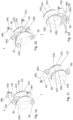
- Figure 1 shows the backside of 4 different variations of a hygienic bearing house (1) according to the present invention defined by figure 1a, figure 1b, figure 1c, and figure 1d .
- the bearing house (1) comprises a bearing house body (2) for receiving a rotating shaft (not shown in figure 1 ), and two or more bearing house feet (4) for attaching the bearing house (1) to a base.
- Each of the two or more bearing house feet (4) extends from the bearing house body (2) by the means of an arm (6).
- Figure 1a shows a bearing house (1) comprising two bearing house feet (4).
- the two bearing house feet (4) are orientated in the longitudinal direction relative to the direction of a rotating shaft to be inserted into the bearing house (1).
- Figure 1b shows a bearing house (1) comprising 4 bearing house feet (4).
- the 4 bearing house feet (4) are orientated in the longitudinal direction relative to the direction of a rotating shaft to be inserted into the bearing house (1).
- Figure 1c shows a bearing house (1) comprising two bearing house feet (4).
- the two bearing house feet (4) are orientated in the perpendicular direction relative to the direction of a rotating shaft to be inserted into the bearing house (1).
- Figure 1d shows a bearing house (1) comprising three bearing house feet (4).
- the three bearing house feet (4) are orientated in the longitudinal direction relative to the direction of a rotating shaft to be inserted into the bearing house (1).
- Figures 1a, 1b, and 1c show bearing house feet (4) that are symmetrically distributed around the bearing house base (2).
- Figure 1d shows a bearing house (1) comprising three bearing house feet (4) where the three bearing house feet (4) are asymmetrically distributed around the bearing house base (2) and one bearing house foot (4) is to attached to the bearing house body (2) via one or more other bearing house foot (4).
- a circular connection of bearing house feet (4) may be provided, see figure 1d .
- the bearing house feet (4) has a length which is larger (determined from the top of the bearing feet (4a) to the base end of the bearing feet (4b)) than the hight of the arm (6).
- the bearing house feet (4) are the only parts of the bearing house which is in contact with the base when the bearing house (1) is attached to the base.
- the open space created between the bearing house body (2) (and the arm (6)) and the base (when attached to the base ) allows for easy access for cleaning the bearing house from all angles.
- the bearing house body (2) comprises a fixed bearing house body (2a) connected, via the arm (6), with the two bearing house feet (4) ( figure 1a and 1c ), the three bearing house feet (4) ( figure 1d ), or the 4 bearing house feet (4) ( figure 1b ), and a removable bearing house cover (2b) which is attached to the fixed bearing house body (2a).
- a removable flat cover (2c) is provided on the opposite site of the fixed bearing house body (2a) and relative to the removable bearing house cover (2b) of.
- the removable flat cover (2c) comprises a shaft insertion (not shown).
- the sealings (3) are configured with contours which are adapted to the structure of the surfaces connected or elements connected and thereby substantially ensure a continuous or substantially continuous surface in the joints between surfaces or elements connected, resulting in that dirt, grime, microbial material (such as bacteria or fungus), or other fouling materials (e.g. allergens), may be hindered or prevented from hiding and/or accumulating.
- a seal (3a) is also provided in the base end of each of the bearing house feet (4b) to avoid accumulation of dirt, grime, microbial material, or other fouling materials in the joint between the bearing house body (2) and the base.
- the seals (3) is prepared from a non-conductive soft silicone material. With a blue color, RAL 5010, which provides an improved visual inspection of the hygienic level and/or cleaning quality.
- the sealings (3) according to the present invention assist in providing a bearing house being waterproof by blocking entering of water, dirt and microbial activity.
- the bearing house feet (4) comprises attachment means (9), such as bolts and nuts for attaching the bearing house (1) to the base.
- the bearing house (1) is made of a sturdy polypropylene material and the surface of the bearing house (1) is made smooth to allow drainage of water from the surface.
- the surface of the bearing house (1) has a roughness below Ra 2.0 ⁇ m; such as Ra 1.8 ⁇ m; e.g. Ra 1.6 ⁇ m; such as Ra 1.4 ⁇ m; e.g. Ra 1.2 ⁇ m; such as Ra 1.0 ⁇ m; e.g. Ra 0.8 ⁇ m; such as Ra 0.6 ⁇ m; e.g. Ra 0.4 ⁇ m.
- a bearing suitable for receiving a rotating shaft is installed inside the bearing house (1) .
- the bearing may be a ceramic bearing or a stainless-steel bearing.
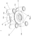
- FIG. 2 shows the front side of a hygienic bearing house (1) according to the present invention.
- the bearing house (1) comprises a bearing house body (2) for receiving a rotating shaft (not shown), and 4 bearing house feet (4) for attaching the bearing house (1) to a base.
- Each of the two or more bearing house feet (4) extends from the bearing house body (2) by the means of a arm (6).
- the bearing house body (2) comprises:
- a bearing is installed suitable for receiving a rotating shaft, and a sealing (3d) is provided which may be in contact with the shaft when the shaft is inserted into the bearing house body (2).
- the sealing (3d) may be formed with a spherical structure.
- the spherical structure of the sealing (3d) has the same, or substantially the same radius as the spherical structure of the outer rim of a bearing inserted into the bearing house (1).
- the spherical structure of the outer rim may be determined in the longitudinal direction of the shaft when inserted into the bearing house (1).
- the arm (6) is formed as a polyhedron, in particular as a triangular prism.
- the first end of the two triangular ends is attached to the bearing house body (2) and the second end of the two triangular parts is attached to one of the two bearing house feet (4).
- the first triangular end has a curative end having a radius relative to the radius of the bearing house body (2) which is larger than the radius of the curative end attached to each of the two bearing house feet (4).
- the arm (6) has a length (l) determining how far each of the two bearing house feet (4) extends from the bearing house body (2); a hight (h) determined in the direction from the bearing house (1) to the base and a width (w) determined in the direction perpendicular to the direction from the bearing house (1) to the base .
- the arm (6) is formed as an integrated part of the fixed bearing house body (2a) and the two bearing house feet (4) during moulding.
- the arm (6) is not in contact with the base when the bearing house (1) is attached to the base.
- the tip (8) of the arm (6) which is formed as a polyhedron, in particular as a triangular prism, is pointing towards the base.
- This structure of the arm (6) improves cleaning around the bearing house with improved access for cleaning from all sides and angles of the bearing house, and improved drainage of water.
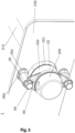
- FIG. 3 shows a hygienic bearing house (1) according to the present invention.
- the bearing house (1) comprises a bearing house body (2) for receiving a rotating shaft (11), and 4 bearing house feet (4) for attaching the bearing house (1) to a base.
- Each of the two or more bearing house feet (4) extends from the bearing house body (2) by the means of a arm (6).
- the bearing house body (2) comprises a fixed bearing house body (2a), a removable bearing house cover (2b); and a removable flat cover (2c) comprising a shaft insertion for inserting the shaft (11).
- the bearing house (1) according to the present invention is attached using attachment means (9), such as bolts, to a base (10) at the base end of the bearing feet (4b), which are the only parts of the bearing house which is in contact with the base (10) when the bearing house (1) is attached to the base a sealing (3a) is provided.
- attachment means (9) such as bolts
- the bearing house body (2) comprises:
- Bearing houses are often one of the places in a hygienic environment, such as a food production site or a pharmaceutical site, where dirt, grime, microbial material (such as bacteria or fungus), or other fouling materials, such as allergens, may hide and accumulate resulting in contaminated products with undesirable components. Accordingly, the inventors of the present invention surprisingly found that simplifying and rebuilding the bearing house, cleaning in, on and around the bearing house may be much easier and the incidence of deposits or accumulation of dirt, grime, microbial material, or allergens, on, in or around the bearing house, may be significantly reduced or even avoided, and at the same time without compromising strength, robustness or stability of the bearing house.
- the present invention relates to a bearing house comprising a bearing house body for receiving a rotating shaft, and two or more bearing house feet for attaching the bearing house to a base, wherein each of the two or more bearing house feet extends from the bearing house body by the means of an arm, wherein at a base end of the bearing feet, which are the only parts of the bearing house which are in contact with the base when the bearing house is attached to the base, a sealing is provided.
- attaching relates to the fixation of one element to another element.
- attaching the bearing house to a base relates to the fixation of the bearing house to the base making it immobile or substantially immobile.
- the bearing house may be provided to support the bearings provided for receiving the rotating shaft.
- the bearing house may also protect the bearings from contaminants while keeping the lubricant inside the bearing house.
- the bearing house may be mounted in a vertical position or in a horizontal position to the base, depending on the application and/or the location of the bearing house.
- One of the unique features of the bearing house according to the present invention may be the projection of the two or more bearing house feet next to the bearing house body by introducing an arm between each of the two or more bearing house feet and the bearing house body.
- the term "extend from” relates to stretching out two or more bearing house feet from the bearing house body.
- the two or more bearing house feet are extended from or stretched out from the bearing house and separated by an arm.
- the arm may be used for extending the bearing house feet from the bearing house body and between two or more bearing house feet. If three or more bearing house feet are connected to each other, one or more bearing house feet may be attached to the bearing house body via another bearing house foot.
- the term "arm” relates to a piece of material used to create or maintain a space between two elements, in particular between each of the two or more bearing house feet and the bearing house body and/or between individual bearing house feet.
- the arm according to the present invention may be constructed to improve and/or ease cleaning in, on or around the bearing house and at the same time to provide strength and stability to the bearing house.
- the arm may preferably provide a distance between the centre of the bearing house and the attachment means by at least 4 mm; such as at least 5 mm; e.g. at least 6 mm; such as at least 7 mm; e.g. at least 8 mm; such as in the range of 4-15 mm; e.g. in the range of 5-12 mm; such as in the range of 6-8 mm.
- a distance between the centre of the bearing house may be determined as the centre of the cross sectional area of the bearing house perpendicular to the longitudinal direction of the rotating shaft when inserted into the bearing house.
- the arm may be made of the same material as the material used in the two or more bearing house feet and/or in the bearing house body.
- the arm may be made of a different material than the material used in the two or more bearing house feet and/or in the bearing house body.
- the bearing house comprise 3 or more bearing house feet each extending from the bearing house body by the means of an arm, such as 4 or more bearing house feet, e.g. 5 or more bearing house feet, such as 6 or more bearing house feet, e.g. 8 or more bearing house feet.
- the bearing house comprises 2-4 bearing house feet, which each extending from the bearing house body by the means of an arm.
- bearing house feet may involve a flange.
- the bearing house feet or the flange may be fitted with attachment means.
- the attachment means may include nuts and bolts where the bolt is going through the bearing house feet or the flange, preferably in longitudinal direction relative to the direction of the bearing house feet or the flange, and through the base.
- each of the two or more bearing house feet may comprises attachment means for attaching the bearing house to the base.
- the base may be a part of a machine, a device, an equipment, or the like.
- the inventors of the present invention surprisingly found that by reducing the amount of material being in contact with the base, areas or spots available for dirt, grime, microbial material and/or other fouling materials to hide and accumulate may be significantly reduced and/or by reconstructing the bearing house it has become easier to clean in, on and around the bearing house with easy access for cleaning from all angles around the bearing house.
- This improved construction surprisingly makes wash-down and cleaning more efficient and/or more reliable resulting in the above-mentioned reductions.
- the two or more bearing house feet are the only part of the bearing house which is in contact with the base.
- bearing house body and/or the arm is/are not in contact with the base.
- the two or more bearing house feet may be the only part of the bearing house which is in contact with the base and/or where the bearing house body and/or the arm is/are not in contact with the base
- an open space is left between the part of the bearing house not in contact with the base (e.g. the bearing house body and/or the arm) and the base.
- the open space between the bearing house body and the base, and/or the open space between the arm and the base is more than 1 mm, such as more than 3 mm, e.g. more than 5 mm, such as more than 1 cm, e.g. more than 1.5 mm, such as more than 2.5 mm, such as in the range of 0.1-5 cm; e.g. in the range of 0.2-3 cm; such as in the range of 0.3-3 cm; e.g. in the range of 0.5-2.75 cm; such as in the range of 0.75-2.54 cm.
- the length of the two or more bearing house feet is in the direction substantially longitudinal to the opening for receiving the rotating shaft.
- the length of the two or more bearing house feet is in the direction substantially perpendicular to the direction of the base where the bearing house is mounted.
- the two or more bearing house feet may be further extended to make an additional distance between the bearing house body and the base.
- the further extension of the two or more bearing house feet may be provided by introducing feet-spacers to each of the two or more bearing house feet until the desired length has been reached.
- a seal is placed between each of the feet-spacers and each of the two or more bearing house feet.
- a seal is placed between each of the feet-spacers and the base.
- substantially perpendicular and/or substantially longitudinal of bearing houses may be subjected to some deviation between 0-20° are considered to be within the range of substantially longitudinal direction, or within the range of substantially perpendicular, to allow some mis alignment without compromising the hygiene safety, strength or stability; such as between 1°-15°, e.g. between 1.5°-10°, such as between 2°-5°, e.g. about 3°.
- the inventors of the present invention have found that by reducing the amount of material used when constructing the bearing house cleaning around the bearing house and cleaning from various angles around the bearing house was much easier and significantly more efficient and/or more reliable resulting in a limitation or even avoiding deposit or accumulation of dirt, grime, microbial material, or allergens, on, in or around the bearing house would be advantageous.
- the inventors of the present invention surprisingly found that in particular the amount of material use for constructing the part between the bearing house body and the two or more bearing house feet may be reduced.
- the inventors of the present invention surprisingly found that by replacing this part of the bearing house (the part between the bearing house body and each of the two or more bearing house feet) may be replaced with an arm according to the present invention without compromising the strength, robustness or stability of the bearing house.
- the arm according to the present invention may have:
- the two or more bearing house feet has a length which is larger (determined from the top of the bearing feet to the base) than the hight of the arm.
- an open space may be provided between the arm and the base. This open space may improve and ease cleaning in, on and around the bearing house and also easier cleaning from various angles of the bearing house, bearing house body, the fixed bearing house body, and/or the two or more bearing house feet.
- the arm may be placed relative to the base and/or the two or more bearing house feet to provide an open space between the arm and the base.
- the open space between the arm and the base is more than 1 mm, such as more than 3 mm, e.g. more than 5 mm, such as more than 1 cm, e.g. more than 1.5 mm, such as more than 2.5 mm; such as in the range of 0.1-5 cm; e.g. in the range of 0.2-3 cm; such as in the range of 0.3-3 cm; e.g. in the range of 0.5-2.75 cm; such as in the range of 0.75-2.54 cm.
- the width of two or more bearing house feet (4) is equal to or smaller than the width of the two or more bearing house feet (4).
- the construction according to the present invention may involve removal of material around the two or more bearing house feet and/or removal of material between the two or more bearing house feet and the bearing house body and the individual elements (such as the two or more bearing house feet; the bearing house body; and/or the arm, may be easily differentiated.
- the arm may be easily distinct from the two or more bearing house feet.
- the arm may be easily distinct from the bearing house body.
- the two or more bearing house feet may be easily distinct from the bearing house body.
- the term "easily distinct” relates to a clear difference between the elements of the bearing house, such as a difference between the bearing house body and the two or more bearing house feet; between the two or more bearing house feet and the arm; and/or between the bearing house body and the arm).
- the difference may be a visual differentiation.
- the fixed bearing house body, the arm and the two or more bearing house feet may be produced, e.g. by moulding, preferably moulded in one piece.
- the design and/or the fabrication of the arm may assist in improving the cleaning and the arm according to the present invention may improve drainage, such as being able to self-drain liquids, such as aqueous suspension, e.g. an aqueous cleaning solution.
- aqueous suspension e.g. an aqueous cleaning solution.
- the arm may be formed as a polyhedron, such as a triangular prism; a square prism; a pentagonal prism; or a hexagonal prism.
- the arm may be formed as a triangular prism.
- the polyhedron may be a frustum.
- frustum relates to a structure topologically identical to a prism, with trapezoid lateral faces and different sized top and bottom polygons.
- the arm comprises a first curvature end aligned with the radius of the bearing house body and a second curvature end aligned with the radius of the bearing house feet.
- the radius of the first curvature end is larger than the radius of the second curvature end.
- curvature end relates to an end that has aligned and adapted to the surface that the end is attached.
- the triangular prism may comprise three rectangular parts and two triangular ends, preferably the two triangular ends have dissimilar dimensions.
- the triangular end being connected to the bearing house has a radius which is larger than the radius of the triangular end being connection to one of the two or more bearing house feet.
- first end of the two triangular ends may be attached to the bearing house body and the second end of the two triangular parts may be attached to one of the two or more bearing house feet.
- the arm may take different forms depending and shapes and at least one edge of the polyhedron, e.g. of the triangular prism, may be straight shaped, concave shaped or convex shaped.
- the at least one edge of the polyhedron e.g. of the triangular prism, is concave shaped and at least one length of the edge of the triangular prism is convex shaped.
- a tip of the polyhedron e.g. of the triangular prism, may be pointing towards the base.
- the term "tip of the polyhedron” relates to one of the edges of the polyhedron, e.g. the triangular prism.
- the one of the edges of the polyhedron, e.g. the triangular prism is pointing toward the base, preferably directly towards the base.
- the bearing house By the above-mentioned structure of the bearing house a limited amount of the bearing house is in contact with the base and/or a larger open space around the bearing house may be provided allowing an easier and more efficient and/or more reliable cleaning resulting in a limitation or even to avoid deposit or accumulation of dirt, grime, microbial material, or allergens, on, in or around the bearing house.
- the bearing inside the bearing house during use and/or for ease installation of a beating and/or a shaft in the bearing house the bearing house body may be provided in different elements which may be joint forming the bearing house body.
- the bearing house body may comprise a fixed bearing house body and a removable bearing house cover attached to the fixed bearing house body.
- the fixed bearing house may preferably be connected to the two or more bearing house feet via the arm according to the present invention.
- the bearing house body may comprise a fixed bearing house body and a removable flat cover comprising a shaft insertion.
- the fixed bearing house may preferably be connected to the two or more bearing house feet via the arm according to the present invention.
- the bearing house body may comprise a fixed bearing house body and a removable bearing house cover attached to the fixed bearing house body and a removable flat cover comprising a shaft insertion.
- the fixed bearing house may preferably be connected to the two or more bearing house feet via the arm according to the present invention.
- the removable flat cover may be attached to the fixed bearing house body, on the opposite side of the fixed bearing house body relative to the removable bearing house cover.
- the bearing house may be provided with a fixed bearing house body and a flat cover
- a seal may be provided between the fixed bearing house body and the flat cover.
- bearing house may be provided with a fixed bearing house body and a removable bearing house cover a seal may be provided between the fixed bearing house body and the removable bearing house cover.
- the fixed bearing house body may comprise a symmetrical structure.
- symmetrical structure relates to a design of the fixed bearing house body and where the removable bearing house cover and the removable flat cover may be attached.
- the symmetrical structure allows attachment of the removable bearing house cover and the removable flat cover on either side of the fixed bearing house body. This allows the bearing house to be attached on both sides of a base depending on the construction to which the bearing house is to be attached and may depend on e.g. space available for the bearing house; cleaning possibilities; and/or functionality.
- the seal/sealings according to the present invention may preferably be configured with contours which are adapted to the structure of the surfaces connected or elements connected and thereby substantially ensure a continuous or substantially continuous surface in the joints between surfaces or elements connected, such as the joints between the fixed bearing house body and the removable bearing house cover; and/or the joints between the two or more bearing house feets and the base and/or the joint between the fixed bearing house body and the flat cover.
- dirt, grime, microbial material such as bacteria or fungus
- other fouling materials such as allergens
- the seal or sealings according to the present invention may be prepared from a non-conductive material.
- the seal, sealings or conductive material may be silicone.
- the seal or sealings may be prepared from soft silicone.
- the seal has a blue color, preferably RAL 5010, which provides an improved visual inspection of the hygienic level and/or cleaning quality.
- the seal comprises a polymer material, preferably the seal comprises essentially a polymeric material.
- the seal (3d) may be a slide bearing.
- the seal according to the present invention may preferably be provided in a one-piece material.
- the polymeric material may comprise an organic compound.
- the organic compound may comprise an inert organic compound.
- the polymer material comprises an olefin compound.
- the olefin compound may be formed like a fiber compound.
- the olefin compound may comprise polypropylene, polyethylene or a combination of polypropylene and polyethylene.
- the seal comprises at least 10% organic compound; such as at least 20%; e.g. at least 30%; such as at least 40%; e.g. at least 50%; such as at least 75%; e.g. at least 80%; such as at least 90%; e.g. at least 95%.
- the seal comprises less than 30% non-organic material; such as less than 20%; e.g. less than 10%; such as less than 5%; e.g. less than 3%; such as less than 1%.
- Non-organic material may include metals, like steel, iron, silicate, or ceramics.
- the seal may comprise a Young modulus (or the modulus of elasticity in tension) in the range of 1000-1500 GPa; such as in the range of 1050-1400 GPa; e.g. in the range of 1100-1200 GPa; such as in the range of 1130-1170 GPa; e.g. in the range of 1140-1160 GPa.
- a Young modulus or the modulus of elasticity in tension
- the Young modulus (or the modulus of elasticity in tension) becomes too low, such as below 1000 GPa, it may be difficult to maintain the shape of the seal. If the Young modulus (or the modulus of elasticity in tension) becomes too high, such as above 1500 GPa the desired elasticity of the seal may be lost.
- Young modulus (or the modulus of elasticity in tension) may relate to a measure of the ability of a material to withstand changes in length when under lengthwise tension or compression.
- the seal may comprise a coefficient of thermal expansion below 20 ⁇ 10 -5 K -1 ; such as 15 ⁇ 10 -5 K -1 or below; e.g. below 13 ⁇ 10 -5 K -1 ; such as 11 ⁇ 10 -5 K -1 or below; e.g. below 10 ⁇ 10 -5 K -1 ; such as 8 ⁇ 10 -5 K -1 or below; e.g. below 6 ⁇ 10 -5 K -1 ; such as in the range of 2 ⁇ 10 -5 K -1 - 20 ⁇ 10 -5 K -1 ; e.g.
- the coefficient of thermal expansion describes how the size of an object changes with a change in temperature. Specifically, it measures the fractional change in size per degree change in temperature at a constant pressure, such that lower coefficients describe lower propensity for change in size.
- the seal comprises a moisture absorption less than 1% (w/w); such as less than 0.9% (w/w); e.g. less than 0.8% (w/w); such as less than 0.7% (w/w); e.g. less than 0.6% (w/w); such as less than 0.5% (w/w); e.g. less than 0.4% (w/w); such as less than 0.3% (w/w); e.g. less than 0.2% (w/w); such as less than 0.1% (w/w).
- w/w moisture absorption less than 1% (w/w); such as less than 0.9% (w/w); e.g. less than 0.8% (w/w); such as less than 0.7% (w/w); e.g. less than 0.6% (w/w); such as less than 0.5% (w/w); e.g. less than 0.4% (w/w); such as less than 0.3% (w/w); e.g. less than 0.2% (w/w); such as less than 0.1% (w
- Moisture absorption as used in the present context relates to the capacity of the seal to absorb moisture from its environment. Absorbed moisture has been shown to act as a plasticizer, reducing the glass transition temperature and strength of plastic - which is a reversible effect.
- the seal comprises a moisture absorption in the range of 0.01-1% (w/w); such as in the range of 0.02-0.9% (w/w); e.g. in the range of 0.03-0.8% (w/w); such as in the range of 0.04-0.7% (w/w); e.g. in the range of 0.05-0.6% (w/w); such as in the range of 0.06-0.5% (w/w); e.g. in the range of 0.07-0.4% (w/w); such as in the range of 0.08-0.3% (w/w); e.g. less than 0.09-0.2% (w/w); such about 0.1% (w/w).
- the seal comprises a max strain of at least 1%; such as at least 2%; e.g. at least 3%; such as at least 4%; e.g. at least 5%.
- the max strain of the seal may relate to the maximum stress necessary in order to provide permanent or irreversible deformation of the seal.
- the seal may, when subjected to a constant stress resulting in a strain of 2%, at 20°C for at most 6 hours, provide at most 50% extension relative to the stain of 2%, such as at most 30%; such as at most 25%; e.g. at most 20%.
- the seal may within 7 days in relax from the stress applied resume to at most 1% extension relative to the stain of 2%, such as at most 0.75%; such as at most 0.5%; e.g. at most 0.25%.
- the seal may comprise a coefficient of friction (determined against steel) in the range of 0.005-0.4, such as in the range of 0.01-0.3; e.g. in the range of 0.05-0.25; such as in the range of 0.075-0.2; e.g. in the range of 0.09-0.19.
- the seal comprises a coefficient of friction (determined against steel) which is below 0.4, such as below 0.3; e.g. below 0.25; such as below 0.2; e.g. below 0.19.
- the term "coefficient of friction” depends on the material against which the friction may be created.
- the “coefficient of friction” according to the present invention may be determined as the material against steel.
- the coefficient of friction may be defined by the friction between the seal (3d) and a shaft (preferably a shaft of steel) when inserted into the bearing house.
- the coefficient of friction may be the ratio defining the force that resists the motion of one body in relation to another body in contact with it. This ratio may be dependent on material properties and may have a value between 0 and 1.
- each of the two or more bearing house feet comprises a sealing between each of the two or more bearing house feet and the base.
- the bearing house may be made of a plastic material or a metal material or a combination hereof.
- the plastic material may be selected from a polypropylene material.
- the polypropylene material may be a sturdy polypropylene material.
- the metal material may be stainless steel.
- all exposed surfaces of the bearing house may have a smooth finish such that dirt, grime, microbial material (such as bacteria or fungus), or other fouling materials, such as allergens, may be cleaned from the surface.
- microbial material such as bacteria or fungus
- other fouling materials such as allergens
- the bearing house according to the present invention may be free of joints, pits, folds, cracks, crevices, and other imperfections in the final fabricated form, when installed on the machinery and/or when working within the specified load conditions.
- none of the exposed surfaces of the bearing house according to the present invention comprising knurled surfaces.
- All the exposed surfaces of the bearing house according to the present invention may preferably be cleanable.
- All the exposed surfaces of the bearing house according to the present invention may preferably be inspectable.
- surface and “exposed surface” may be used interchangeably and relates to any surface that may be accessible to dirt, grime, microbial material (such as bacteria or fungus), or other fouling materials, such as allergens.
- microbial material such as bacteria or fungus
- other fouling materials such as allergens.
- all the exposed surfaces of the bearing house according to the present invention may be self-draining.
- the bearing house comprises no surfaces which has one or more pockets which may retain liquids.
- self-draining relates to a surface constructed, designed and/or fabricated in a manner allowing aqueous suspension, such as aqueous cleaning suspension, like water, to escape and/or leaving the surface.
- aqueous suspension such as aqueous cleaning suspension, like water
- cleaning of the bearing house may be by manual cleaning.
- removal of dirt, grime, microbial material, or other fouling materials may be affected by an aqueous suspension, e.g. chemical and/or water rinses, optionally with the assistance of one or a combination of brushes, nonmetallic scouring pads and scrapers.
- Rinses may be performed by high- or low-pressure hoses, and/or with cleaning aids manipulated by hand.
- the surface of the bearing house may be a smooth surface.
- the surface of the bearing house may be smooth.
- the smooth surface of the bearing house may allow drainage, preferably self-drainage, of liquids from the surface.
- Smoothness of the exposed surface of the bearing house according to the present invention may be determined by the "Roughness Average (Ra)".
- Roughness Average or Ra is an arithmetical mean of the absolute values of the surface profile departure within a sampling length.
- the roughness (Ra) of the surface of the bearing house may be determined according to the ISO 4287:1997 standard.
- the surface of the bearing house according to the present invention may comprise all the exposed surfaces of the bearing house.
- the surface of the bearing house may have a roughness below Ra 2.0 ⁇ m; such as Ra 1.8 ⁇ m; e.g. Ra 1.6 ⁇ m; such as Ra 1.4 ⁇ m; e.g. Ra 1.2 ⁇ m; such as Ra 1.0 ⁇ m; e.g. Ra 0.8 ⁇ m; such as Ra 0.6 ⁇ m; e.g. Ra 0.4 ⁇ m.
- the bearing house according to the present invention comprises no exposed surfaces; ledges and/or edges which are horizontal.
- the bearing house all exposed surfaces; ledges and/or edges are curvilinear or curved.
- ledges and/or edges of the bearing house may have an angle, may be founded or has a curvature relative to horizontal.
- At least one of the exposed surfaces; ledges and/or edges of the bearing house, preferably all exposed surfaces; ledges and/or edges, may have a radius of 1 mm or above improving water runoff from at least one of the exposed surfaces, preferably all the exposed surfaces; ledges and/or edges of the bearing house; such as a radius of 2 mm or above; e.g. a radius of as 3 mm or above, such as a radius of 3.2 mm or above; e.g. a radius of 3.5 mm or above; such as a radius of 4 mm or above, e.g. 5 mm or above.
- the bearing house comprises no exposed surfaces; ledges and/or edges having a radius below 3.2 mm; such as below 3 mm; e.g. below 2.5 mm; such as below 1 mm; e.g. below 0.8 mm.
- all the exposed surfaces; ledges and/or edges of the bearing house may have an angle, may be founded or has a curvature of at least 3 degree relative to horizontal; e.g. 3.2 degree or above relative to horizontal, such as 3.5 degree or above relative to horizontal; e.g. 3.75 degree or above relative to horizontal; such as 4 degree or above relative to horizontal, e.g. 5 degree or above relative to horizontal.
- the exposed surfaces, ledges and/or edges of the bearing house may be constructed, designed and/or fabricated in accordance with national standards and/or directives, like one or more of:
- the bearing house according to the present invention may be provided with a bearing.
- a bearing according to the present invention may be a machine element that constrains relative motion to only the desired motion, and reduces friction between moving parts, e.g. a shaft, relative to a non-moving parts, e.g. the bearing house.
- the bearing house may comprise a bearing suitable for receiving a rotating shaft.
- the bearing may be a ceramic bearing or a stainless steel bearing.
- the bearing may be a ceramic bearing.
- the beating may be a fat free and/or a lubricant free bearing. Due to the construction, design and fabrication of the bearing house and the reduced number of elements joint and protected by a sealing ensure a waterproof bearing house, preferably a long-term waterproof property, the bearing house according to the present invention.
- the bearing house consist essentially of a bearing house body having two or more bearing house feet (preferably between 2 and 4 bearing house feet) extending from the bearing house body by means of an arm, a joint (and a sealing) between the bearing house body and a removable flat cover; a joint (and a sealing) between the bearing house body and a removable bearing house cover; a joint (and a sealing) between each of the bearing house feet of the bearing house body and the base; and a joint (and a sealing) between each of the bearing house feet of the bearing house body and each of the bolts used to attach the bearing house to the base.
- the bearing house may be a hygienic bearing house.
- the term "hygienic bearing house” relates to a bearing house adapted for reducing or preventing dirt, grime, microbial material, or other kind of fouling to access gap; joints; pits; folds; cracks; crevices; or other imperfections, in or between connecting surfaces or elements.
- the bearing house according to the present invention may be used in environments with high hygienic requirements, high cleaning requirements and/or environments where low (or no) deposit or accumulation of dirt, grime, microbial material and/or allergens may be accepted.
- a further preferred embodiment relates to the use of the bearing house according to the present invention for use in food production industry, feed production industry, and/or pharmaceutical industry.
- the bearing house according to the present invention may be provided with a built-in sensor.
- the built-in sensor may transmit data, such as operating data or construction data to a mobile device and/or to a cloud surveillance of the bearing house.
- the senor is implemented into the removable bearing house cover.
- the senor may be configures to monitor one or more of vibrations, temperature, leakage, moisture, exterior cleaning and/or location of the bearing house.
Landscapes
- Engineering & Computer Science (AREA)
- General Engineering & Computer Science (AREA)
- Mechanical Engineering (AREA)
- Rolling Contact Bearings (AREA)
- Sliding-Contact Bearings (AREA)
- Gasket Seals (AREA)
- Mounting Of Bearings Or Others (AREA)
- Load-Bearing And Curtain Walls (AREA)
Claims (15)
- Lagergehäuse (1), umfassend einen Lagergehäusekörper (2) zum Aufnehmen einer rotierenden Welle und zwei oder mehr Lagergehäuse-Standfüße (4) zum Befestigen des Lagergehäuses (1) an einer Basis (10), wobei sich jeder der zwei oder mehr Lagergehäuse-Standfüße (4) mittels eines Arms (6) von dem Lagergehäusekörper (2) erstreckt, wobei an einem Basisende der Lagerstandfüße, welche die einzigen Teile des Lagergehäuses sind, die mit der Basis in Kontakt stehen, wenn das Lagergehäuse an der Basis befestigt ist, eine Dichtung (3a) bereitgestellt ist.
- Lagergehäuse (1) nach Anspruch 1, wobei der Arm (6) als Polyeder, wie etwa ein Dreiecksprisma; ein Viereckprisma; ein Fünfeckprisma; oder ein Sechseckprisma ausgebildet ist. Vorzugsweise ist der Arm (6) als Dreiecksprisma ausgebildet.
- Lagergehäuse (1) nach einem der vorhergehenden Ansprüche, wobei die zwei oder mehr Lagergehäuse-Standfüße (4) die einzigen Teile des Lagergehäuses (1) sind, der mit der Basis (10) in Kontakt stehen, wenn das Lagergehäuse an der Basis befestigt ist.
- Lagergehäuse (1) nach einem der vorhergehenden Ansprüche, wobei die Länge der zwei oder mehr Lagergehäuse-Standfüße (4) in der Richtung im Wesentlichen längs zu einer Öffnung zum Aufnehmen der rotierenden Welle und/oder im Wesentlichen senkrecht zu der Richtung der Basis (10), an der das Lagergehäuse (1) montiert ist, verläuft.
- Lagergehäuse (1) nach einem der Ansprüche 2-4, wobei eine Spitze (8) des Polyeders, z. B. des Dreiecksprismas, in Richtung der Basis (10) weist.
- Lagergehäuse (1) nach einem der vorhergehenden Ansprüche, wobei jeder der zwei oder mehr Lagergehäuse-Standfüße (4) eine Dichtung zwischen jedem der zwei oder mehr Lagergehäuse-Standfüße (4) und der Basis (10) umfasst, wenn das Lagergehäuse an der Basis befestigt ist.
- Lagergehäuse (1) nach einem der vorhergehenden Ansprüche, wobei das Lagergehäuse (1) aus einem Kunststoffmaterial, insbesondere einem Kunststoffmaterial, das aus einem Polypropylenmaterial ausgewählt ist, hergestellt ist.
- Lagergehäuse (1) nach einem der vorhergehenden Ansprüche, wobei das Lagergehäuse (1) ein Hygienelagergehäuse ist.
- Lagergehäuse (1) nach einem der vorhergehenden Ansprüche, wobei der Lagergehäusekörper einen feststehenden Lagergehäusekörper und eine entfernbare Lagergehäuseabdeckung, die an dem feststehenden Lagergehäusekörper befestigt ist, umfasst und/oder der Lagergehäusekörper einen feststehenden Lagergehäusekörper und eine entfernbare flache Abdeckung umfasst, die einen Welleneinsatz umfasst.
- Lagergehäuse (1) nach Anspruch 9, wobei eine Dichtung (3c) zwischen dem feststehenden Lagergehäusekörper und der flachen Abdeckung bereitgestellt ist, und/oder wobei eine Dichtung (3b) zwischen dem feststehenden Lagergehäusekörper und der entfernbaren Lagergehäuseabdeckung bereitgestellt ist.
- Lagergehäuse (1) nach einem der vorhergehenden Ansprüche, wobei der Lagergehäusekörper (2) einen feststehenden Lagergehäusekörper (2a), eine entfernbare flache Abdeckung (2c), die einem Welleneinsatz (7) umfasst, umfasst, wobei im eingebauten Zustand innerhalb der Lagergehäusebasis (2) ein Lager zum Aufnehmen der rotierenden Welle geeignet ist und eine Dichtung (3d) bereitgestellt ist, die in Kontakt mit der Welle steht, wenn die Welle in den Lagergehäusekörper (2) eingesetzt ist.
- Lagergehäuse (1) nach Anspruch 11, wobei die Dichtung (3d) mit einer Kugelstruktur ausgebildet ist und die Kugelstruktur der Dichtung (3d) den gleichen oder im Wesentlichen den gleichen Radius wie die Kugelstruktur eines äußeren Randes eines Lagers aufweist, wenn sie in das Lagergehäuse (1) eingesetzt ist.
- Lagergehäuse (1) nach einem der Ansprüche 11-12, wobei die Dichtung (3d) ein Gleitlager ist.
- Verwendung des Lagerhauses (1) nach einem der Ansprüche 1-13 zur Verwendung in Umgebungen mit hohen hygienischen Anforderungen, hohen Reinigungsanforderungen und/oder Umgebungen, in denen geringe (oder keine) Ablagerung oder Ansammlung von Verschmutzung, Schmutz, mikrobiellem Material und/oder Allergenen akzeptabel ist.
- Verwendung des Lagerhauses (1) nach einem der Ansprüche 1-13 zur Verwendung in der Lebensmittelproduktionsindustrie, Futtermittelproduktionsindustrie und/oder pharmazeutischen Industrie.
Applications Claiming Priority (3)
| Application Number | Priority Date | Filing Date | Title |
|---|---|---|---|
| DKPA202000112 | 2020-01-30 | ||
| DKPA202001452 | 2020-12-22 | ||
| PCT/EP2021/051936 WO2021151983A1 (en) | 2020-01-30 | 2021-01-28 | Bearing house design |
Publications (3)
| Publication Number | Publication Date |
|---|---|
| EP4097368A1 EP4097368A1 (de) | 2022-12-07 |
| EP4097368C0 EP4097368C0 (de) | 2024-12-04 |
| EP4097368B1 true EP4097368B1 (de) | 2024-12-04 |
Family
ID=74418452
Family Applications (1)
| Application Number | Title | Priority Date | Filing Date |
|---|---|---|---|
| EP21702453.8A Active EP4097368B1 (de) | 2020-01-30 | 2021-01-28 | Lagergehäusekonstruktion |
Country Status (8)
| Country | Link |
|---|---|
| US (1) | US12385528B2 (de) |
| EP (1) | EP4097368B1 (de) |
| JP (1) | JP2023511841A (de) |
| CN (1) | CN115023559A (de) |
| AU (1) | AU2021214723A1 (de) |
| CA (1) | CA3162250A1 (de) |
| ES (1) | ES3004141T3 (de) |
| WO (1) | WO2021151983A1 (de) |
Families Citing this family (6)
| Publication number | Priority date | Publication date | Assignee | Title |
|---|---|---|---|---|
| CA202539S (en) * | 2021-02-16 | 2022-09-21 | Ngi As | Ball bearing |
| USD1040200S1 (en) * | 2022-03-28 | 2024-08-27 | Marco Fenu | Bearing housing |
| USD1056007S1 (en) * | 2022-03-28 | 2024-12-31 | Marco Fenu | Bearing housing |
| USD1056006S1 (en) * | 2022-03-28 | 2024-12-31 | Marco Fenu | Bearing housing |
| EP4686850A1 (de) * | 2024-07-30 | 2026-02-04 | Aktiebolaget SKF | Hülle für lebensmittelanwendungen |
| EP4686851A1 (de) * | 2024-07-30 | 2026-02-04 | Aktiebolaget SKF | Hülle für lebensmittelanwendungen |
Family Cites Families (29)
| Publication number | Priority date | Publication date | Assignee | Title |
|---|---|---|---|---|
| US2819128A (en) | 1953-12-17 | 1958-01-07 | Fafnir Bearing Co | Bearing |
| AU491250B2 (en) | 1975-07-23 | 1977-02-10 | Reliance Electric Company | Shaft bearing |
| US4033641A (en) | 1976-03-05 | 1977-07-05 | Tribotech | Flange mount |
| JPS57133419U (de) * | 1981-02-13 | 1982-08-19 | ||
| JPH0113848Y2 (de) * | 1984-10-30 | 1989-04-24 | ||
| IT224005Z2 (it) | 1990-12-07 | 1995-11-08 | Skf Ind Spa | Sopporto universale per alberi rotanti |
| US5129737A (en) * | 1991-01-28 | 1992-07-14 | G. H. Stenner & Co. | Motor bearing and bracket therefor |
| DE4224179C1 (de) * | 1992-07-22 | 1993-11-11 | Freudenberg Carl Fa | Führungshülse mit integrierter Dichtung für ein Kupplungsausrücklager eines Getriebes |
| US5328276A (en) * | 1992-11-12 | 1994-07-12 | Michel Linteau | Bearing mounting for shafts |
| DE19546676A1 (de) * | 1995-12-15 | 1997-06-19 | Schaeffler Waelzlager Kg | Lagergehäuse mit einer Schutzkappe |
| US5927864A (en) | 1996-09-12 | 1999-07-27 | Emerson Power Transmission Corp. | Bearing assembly with self-contained auxiliary seal |
| JP2001050272A (ja) * | 1999-08-09 | 2001-02-23 | Takashi Ichihara | ベアリングユニット |
| US6193418B1 (en) * | 2000-01-18 | 2001-02-27 | Fyh Bearing Units Usa, Inc. | Safety end cap for rotary bearing |
| JP3842232B2 (ja) * | 2003-03-20 | 2006-11-08 | 三菱電機株式会社 | 電動機の軸受用潤滑油の封止構造 |
| DE10334898B4 (de) * | 2003-07-29 | 2007-02-22 | Ab Skf | Halteelement zur Fixierung wenigstens eines Lagers |
| JP2010032470A (ja) * | 2008-07-31 | 2010-02-12 | Nippon Seiki Co Ltd | ケースの防水構造 |
| JP5364622B2 (ja) * | 2010-03-04 | 2013-12-11 | トヨタ車体株式会社 | 車両用パッキン並びにこれを用いた車両部品の固定方法及び固定構造 |
| CN202326759U (zh) * | 2011-11-08 | 2012-07-11 | 攀枝花市三圣机械制造有限责任公司 | 密封式结构化轴承箱 |
| CN105705443B (zh) * | 2013-07-26 | 2017-09-12 | 雷勃电气美国公司 | 轴承支座装置 |
| JP5732510B2 (ja) * | 2013-10-21 | 2015-06-10 | 株式会社日立産機システム | 圧縮機 |
| JP2017106592A (ja) * | 2015-12-11 | 2017-06-15 | 株式会社荏原製作所 | 軸受装置及び回転機械システム |
| JP6332261B2 (ja) * | 2015-12-25 | 2018-05-30 | トヨタ自動車株式会社 | 軸受支持装置 |
| JP6893004B2 (ja) * | 2016-09-01 | 2021-06-23 | 矢崎化工株式会社 | パイプ継手 |
| US10240638B2 (en) * | 2017-07-28 | 2019-03-26 | GM Global Technology Operations LLC | Cartridge bearing with bearing grease setting member |
| CN208417288U (zh) * | 2018-06-19 | 2019-01-22 | 烟台百润机械有限公司 | 过滤机用多重密封式轴承座 |
| JP7045950B2 (ja) * | 2018-07-17 | 2022-04-01 | 中央可鍛工業株式会社 | 軸受装置 |
| CN208605506U (zh) * | 2018-08-01 | 2019-03-15 | 北京汽车研究总院有限公司 | 一种轴承座和具有其的车辆 |
| CN209354539U (zh) * | 2019-01-08 | 2019-09-06 | 曲阜市鑫华矿山配件有限公司 | 一种冲压轴承座密封结构 |
| CA202539S (en) * | 2021-02-16 | 2022-09-21 | Ngi As | Ball bearing |
-
2021
- 2021-01-28 WO PCT/EP2021/051936 patent/WO2021151983A1/en not_active Ceased
- 2021-01-28 EP EP21702453.8A patent/EP4097368B1/de active Active
- 2021-01-28 CA CA3162250A patent/CA3162250A1/en active Pending
- 2021-01-28 CN CN202180011283.8A patent/CN115023559A/zh active Pending
- 2021-01-28 JP JP2022540314A patent/JP2023511841A/ja active Pending
- 2021-01-28 ES ES21702453T patent/ES3004141T3/es active Active
- 2021-01-28 AU AU2021214723A patent/AU2021214723A1/en active Pending
- 2021-01-28 US US17/790,240 patent/US12385528B2/en active Active
Also Published As
| Publication number | Publication date |
|---|---|
| CN115023559A (zh) | 2022-09-06 |
| AU2021214723A1 (en) | 2022-06-30 |
| JP2023511841A (ja) | 2023-03-23 |
| EP4097368A1 (de) | 2022-12-07 |
| ES3004141T3 (en) | 2025-03-11 |
| WO2021151983A1 (en) | 2021-08-05 |
| EP4097368C0 (de) | 2024-12-04 |
| US20230040152A1 (en) | 2023-02-09 |
| US12385528B2 (en) | 2025-08-12 |
| CA3162250A1 (en) | 2021-08-05 |
Similar Documents
| Publication | Publication Date | Title |
|---|---|---|
| EP4097368B1 (de) | Lagergehäusekonstruktion | |
| JP2026020391A (ja) | 軸受収容部用の衛生的なシーリング | |
| US11420344B2 (en) | Smooth surfaced flexible and stretchable skin for covering robotic arms in restaurant and food preparation applications | |
| US20050092122A1 (en) | Manipulator with automatic control, especially for the food industry | |
| US20250314274A1 (en) | Bearing house design | |
| WO2024094554A1 (en) | Bearing housing | |
| CA3238194A1 (en) | Anti-static bearing house | |
| US5971618A (en) | Flange bearing having reinforced molded housing | |
| EP0566627B1 (de) | Lager für walzen und dergleichen | |
| US20150260289A1 (en) | Sealing profile and system for sealing a clamp | |
| CN114340447B (zh) | 用于容器处理机的机器脚 | |
| AU2024315839A1 (en) | Nut and bolt for hygienic application | |
| WO2025027176A1 (en) | Nut and bolt for hygienic application | |
| Gaceu | Design principles for assuring food safety in Romanian mountain dairy farms. | |
| EP1621804B1 (de) | Dichtungsanordnung | |
| EP1816220A4 (de) | Edelstahlblech für dichtung und herstellungsverfahren dafür | |
| Moerman | Hygienic Design of Closed Equipment for the Processing | |
| Baker | Hygienic design of food-processing equipment | |
| WO2001042422A3 (en) | Acyl glucosaminyl inositol amidase family and methods of use | |
| JPH074617U (ja) | カ−テンウォ−ルユニット | |
| Crompton | Standing and Walking listings |
Legal Events
| Date | Code | Title | Description |
|---|---|---|---|
| STAA | Information on the status of an ep patent application or granted ep patent |
Free format text: STATUS: UNKNOWN |
|
| STAA | Information on the status of an ep patent application or granted ep patent |
Free format text: STATUS: THE INTERNATIONAL PUBLICATION HAS BEEN MADE |
|
| PUAI | Public reference made under article 153(3) epc to a published international application that has entered the european phase |
Free format text: ORIGINAL CODE: 0009012 |
|
| STAA | Information on the status of an ep patent application or granted ep patent |
Free format text: STATUS: REQUEST FOR EXAMINATION WAS MADE |
|
| 17P | Request for examination filed |
Effective date: 20220830 |
|
| AK | Designated contracting states |
Kind code of ref document: A1 Designated state(s): AL AT BE BG CH CY CZ DE DK EE ES FI FR GB GR HR HU IE IS IT LI LT LU LV MC MK MT NL NO PL PT RO RS SE SI SK SM TR |
|
| DAV | Request for validation of the european patent (deleted) | ||
| DAX | Request for extension of the european patent (deleted) | ||
| GRAP | Despatch of communication of intention to grant a patent |
Free format text: ORIGINAL CODE: EPIDOSNIGR1 |
|
| STAA | Information on the status of an ep patent application or granted ep patent |
Free format text: STATUS: GRANT OF PATENT IS INTENDED |
|
| INTG | Intention to grant announced |
Effective date: 20240117 |
|
| GRAJ | Information related to disapproval of communication of intention to grant by the applicant or resumption of examination proceedings by the epo deleted |
Free format text: ORIGINAL CODE: EPIDOSDIGR1 |
|
| STAA | Information on the status of an ep patent application or granted ep patent |
Free format text: STATUS: REQUEST FOR EXAMINATION WAS MADE |
|
| INTC | Intention to grant announced (deleted) | ||
| GRAP | Despatch of communication of intention to grant a patent |
Free format text: ORIGINAL CODE: EPIDOSNIGR1 |
|
| STAA | Information on the status of an ep patent application or granted ep patent |
Free format text: STATUS: GRANT OF PATENT IS INTENDED |
|
| INTG | Intention to grant announced |
Effective date: 20240703 |
|
| GRAS | Grant fee paid |
Free format text: ORIGINAL CODE: EPIDOSNIGR3 |
|
| GRAA | (expected) grant |
Free format text: ORIGINAL CODE: 0009210 |
|
| STAA | Information on the status of an ep patent application or granted ep patent |
Free format text: STATUS: THE PATENT HAS BEEN GRANTED |
|
| AK | Designated contracting states |
Kind code of ref document: B1 Designated state(s): AL AT BE BG CH CY CZ DE DK EE ES FI FR GB GR HR HU IE IS IT LI LT LU LV MC MK MT NL NO PL PT RO RS SE SI SK SM TR |
|
| REG | Reference to a national code |
Ref country code: CH Ref legal event code: EP |
|
| REG | Reference to a national code |
Ref country code: DE Ref legal event code: R096 Ref document number: 602021022814 Country of ref document: DE |
|
| REG | Reference to a national code |
Ref country code: IE Ref legal event code: FG4D |
|
| U01 | Request for unitary effect filed |
Effective date: 20241227 |
|
| U07 | Unitary effect registered |
Designated state(s): AT BE BG DE DK EE FI FR IT LT LU LV MT NL PT RO SE SI Effective date: 20250114 |
|
| U20 | Renewal fee for the european patent with unitary effect paid |
Year of fee payment: 5 Effective date: 20250127 |
|
| REG | Reference to a national code |
Ref country code: ES Ref legal event code: FG2A Ref document number: 3004141 Country of ref document: ES Kind code of ref document: T3 Effective date: 20250311 |
|
| PG25 | Lapsed in a contracting state [announced via postgrant information from national office to epo] |
Ref country code: HR Free format text: LAPSE BECAUSE OF FAILURE TO SUBMIT A TRANSLATION OF THE DESCRIPTION OR TO PAY THE FEE WITHIN THE PRESCRIBED TIME-LIMIT Effective date: 20241204 |
|
| PGFP | Annual fee paid to national office [announced via postgrant information from national office to epo] |
Ref country code: ES Payment date: 20250203 Year of fee payment: 5 |
|
| PG25 | Lapsed in a contracting state [announced via postgrant information from national office to epo] |
Ref country code: NO Free format text: LAPSE BECAUSE OF FAILURE TO SUBMIT A TRANSLATION OF THE DESCRIPTION OR TO PAY THE FEE WITHIN THE PRESCRIBED TIME-LIMIT Effective date: 20250304 |
|
| PG25 | Lapsed in a contracting state [announced via postgrant information from national office to epo] |
Ref country code: GR Free format text: LAPSE BECAUSE OF FAILURE TO SUBMIT A TRANSLATION OF THE DESCRIPTION OR TO PAY THE FEE WITHIN THE PRESCRIBED TIME-LIMIT Effective date: 20250305 |
|
| PGFP | Annual fee paid to national office [announced via postgrant information from national office to epo] |
Ref country code: CH Payment date: 20250201 Year of fee payment: 5 |
|
| PGFP | Annual fee paid to national office [announced via postgrant information from national office to epo] |
Ref country code: CZ Payment date: 20250107 Year of fee payment: 5 |
|
| PGFP | Annual fee paid to national office [announced via postgrant information from national office to epo] |
Ref country code: GB Payment date: 20250127 Year of fee payment: 5 |
|
| PG25 | Lapsed in a contracting state [announced via postgrant information from national office to epo] |
Ref country code: RS Free format text: LAPSE BECAUSE OF FAILURE TO SUBMIT A TRANSLATION OF THE DESCRIPTION OR TO PAY THE FEE WITHIN THE PRESCRIBED TIME-LIMIT Effective date: 20250304 |
|
| PG25 | Lapsed in a contracting state [announced via postgrant information from national office to epo] |
Ref country code: SM Free format text: LAPSE BECAUSE OF FAILURE TO SUBMIT A TRANSLATION OF THE DESCRIPTION OR TO PAY THE FEE WITHIN THE PRESCRIBED TIME-LIMIT Effective date: 20241204 |
|
| PG25 | Lapsed in a contracting state [announced via postgrant information from national office to epo] |
Ref country code: PL Free format text: LAPSE BECAUSE OF FAILURE TO SUBMIT A TRANSLATION OF THE DESCRIPTION OR TO PAY THE FEE WITHIN THE PRESCRIBED TIME-LIMIT Effective date: 20241204 |
|
| PG25 | Lapsed in a contracting state [announced via postgrant information from national office to epo] |
Ref country code: IS Free format text: LAPSE BECAUSE OF FAILURE TO SUBMIT A TRANSLATION OF THE DESCRIPTION OR TO PAY THE FEE WITHIN THE PRESCRIBED TIME-LIMIT Effective date: 20250404 |
|
| PG25 | Lapsed in a contracting state [announced via postgrant information from national office to epo] |
Ref country code: SK Free format text: LAPSE BECAUSE OF FAILURE TO SUBMIT A TRANSLATION OF THE DESCRIPTION OR TO PAY THE FEE WITHIN THE PRESCRIBED TIME-LIMIT Effective date: 20241204 |
|
| PG25 | Lapsed in a contracting state [announced via postgrant information from national office to epo] |
Ref country code: MC Free format text: LAPSE BECAUSE OF FAILURE TO SUBMIT A TRANSLATION OF THE DESCRIPTION OR TO PAY THE FEE WITHIN THE PRESCRIBED TIME-LIMIT Effective date: 20241204 |
|
| PLBE | No opposition filed within time limit |
Free format text: ORIGINAL CODE: 0009261 |
|
| STAA | Information on the status of an ep patent application or granted ep patent |
Free format text: STATUS: NO OPPOSITION FILED WITHIN TIME LIMIT |
|
| REG | Reference to a national code |
Ref country code: CH Ref legal event code: L10 Free format text: ST27 STATUS EVENT CODE: U-0-0-L10-L00 (AS PROVIDED BY THE NATIONAL OFFICE) Effective date: 20251015 |
|
| 26N | No opposition filed |
Effective date: 20250905 |
|
| PG25 | Lapsed in a contracting state [announced via postgrant information from national office to epo] |
Ref country code: IE Free format text: LAPSE BECAUSE OF NON-PAYMENT OF DUE FEES Effective date: 20250128 |
|
| REG | Reference to a national code |
Ref country code: CH Ref legal event code: U11 Free format text: ST27 STATUS EVENT CODE: U-0-0-U10-U11 (AS PROVIDED BY THE NATIONAL OFFICE) Effective date: 20260201 |