EP4097358B1 - Halterung zur befestigung einer vorrichtung - Google Patents
Halterung zur befestigung einer vorrichtung Download PDFInfo
- Publication number
- EP4097358B1 EP4097358B1 EP21700064.5A EP21700064A EP4097358B1 EP 4097358 B1 EP4097358 B1 EP 4097358B1 EP 21700064 A EP21700064 A EP 21700064A EP 4097358 B1 EP4097358 B1 EP 4097358B1
- Authority
- EP
- European Patent Office
- Prior art keywords
- bracket
- securing element
- adapters
- elongate structure
- bosses
- Prior art date
- Legal status (The legal status is an assumption and is not a legal conclusion. Google has not performed a legal analysis and makes no representation as to the accuracy of the status listed.)
- Active
Links
Images


Classifications
-
- F—MECHANICAL ENGINEERING; LIGHTING; HEATING; WEAPONS; BLASTING
- F16—ENGINEERING ELEMENTS AND UNITS; GENERAL MEASURES FOR PRODUCING AND MAINTAINING EFFECTIVE FUNCTIONING OF MACHINES OR INSTALLATIONS; THERMAL INSULATION IN GENERAL
- F16M—FRAMES, CASINGS OR BEDS OF ENGINES, MACHINES OR APPARATUS, NOT SPECIFIC TO ENGINES, MACHINES OR APPARATUS PROVIDED FOR ELSEWHERE; STANDS; SUPPORTS
- F16M13/00—Other supports for positioning apparatus or articles; Means for steadying hand-held apparatus or articles
- F16M13/02—Other supports for positioning apparatus or articles; Means for steadying hand-held apparatus or articles for supporting on, or attaching to, an object, e.g. tree, gate, window-frame, cycle
-
- E—FIXED CONSTRUCTIONS
- E04—BUILDING
- E04B—GENERAL BUILDING CONSTRUCTIONS; WALLS, e.g. PARTITIONS; ROOFS; FLOORS; CEILINGS; INSULATION OR OTHER PROTECTION OF BUILDINGS
- E04B9/00—Ceilings; Construction of ceilings, e.g. false ceilings; Ceiling construction with regard to insulation
- E04B9/006—Ceilings; Construction of ceilings, e.g. false ceilings; Ceiling construction with regard to insulation with means for hanging lighting fixtures or other appliances to the framework of the ceiling
-
- F—MECHANICAL ENGINEERING; LIGHTING; HEATING; WEAPONS; BLASTING
- F04—POSITIVE - DISPLACEMENT MACHINES FOR LIQUIDS; PUMPS FOR LIQUIDS OR ELASTIC FLUIDS
- F04B—POSITIVE-DISPLACEMENT MACHINES FOR LIQUIDS; PUMPS
- F04B53/00—Component parts, details or accessories not provided for in, or of interest apart from, groups F04B1/00 - F04B23/00 or F04B39/00 - F04B47/00
- F04B53/16—Casings; Cylinders; Cylinder liners or heads; Fluid connections
-
- F—MECHANICAL ENGINEERING; LIGHTING; HEATING; WEAPONS; BLASTING
- F04—POSITIVE - DISPLACEMENT MACHINES FOR LIQUIDS; PUMPS FOR LIQUIDS OR ELASTIC FLUIDS
- F04B—POSITIVE-DISPLACEMENT MACHINES FOR LIQUIDS; PUMPS
- F04B53/00—Component parts, details or accessories not provided for in, or of interest apart from, groups F04B1/00 - F04B23/00 or F04B39/00 - F04B47/00
- F04B53/001—Noise damping
- F04B53/003—Noise damping by damping supports
-
- F—MECHANICAL ENGINEERING; LIGHTING; HEATING; WEAPONS; BLASTING
- F04—POSITIVE - DISPLACEMENT MACHINES FOR LIQUIDS; PUMPS FOR LIQUIDS OR ELASTIC FLUIDS
- F04B—POSITIVE-DISPLACEMENT MACHINES FOR LIQUIDS; PUMPS
- F04B53/00—Component parts, details or accessories not provided for in, or of interest apart from, groups F04B1/00 - F04B23/00 or F04B39/00 - F04B47/00
- F04B53/22—Arrangements for enabling ready assembly or disassembly
-
- F—MECHANICAL ENGINEERING; LIGHTING; HEATING; WEAPONS; BLASTING
- F16—ENGINEERING ELEMENTS AND UNITS; GENERAL MEASURES FOR PRODUCING AND MAINTAINING EFFECTIVE FUNCTIONING OF MACHINES OR INSTALLATIONS; THERMAL INSULATION IN GENERAL
- F16B—DEVICES FOR FASTENING OR SECURING CONSTRUCTIONAL ELEMENTS OR MACHINE PARTS TOGETHER, e.g. NAILS, BOLTS, CIRCLIPS, CLAMPS, CLIPS OR WEDGES; JOINTS OR JOINTING
- F16B5/00—Joining sheets or plates, e.g. panels, to one another or to strips or bars parallel to them
- F16B5/06—Joining sheets or plates, e.g. panels, to one another or to strips or bars parallel to them by means of clamps or clips
- F16B5/0685—Joining sheets or plates to strips or bars
-
- F—MECHANICAL ENGINEERING; LIGHTING; HEATING; WEAPONS; BLASTING
- F24—HEATING; RANGES; VENTILATING
- F24F—AIR-CONDITIONING; AIR-HUMIDIFICATION; VENTILATION; USE OF AIR CURRENTS FOR SCREENING
- F24F13/00—Details common to, or for air-conditioning, air-humidification, ventilation or use of air currents for screening
- F24F13/22—Means for preventing condensation or evacuating condensate
- F24F13/222—Means for preventing condensation or evacuating condensate for evacuating condensate
-
- F—MECHANICAL ENGINEERING; LIGHTING; HEATING; WEAPONS; BLASTING
- F16—ENGINEERING ELEMENTS AND UNITS; GENERAL MEASURES FOR PRODUCING AND MAINTAINING EFFECTIVE FUNCTIONING OF MACHINES OR INSTALLATIONS; THERMAL INSULATION IN GENERAL
- F16B—DEVICES FOR FASTENING OR SECURING CONSTRUCTIONAL ELEMENTS OR MACHINE PARTS TOGETHER, e.g. NAILS, BOLTS, CIRCLIPS, CLAMPS, CLIPS OR WEDGES; JOINTS OR JOINTING
- F16B21/00—Means for preventing relative axial movement of a pin, spigot, shaft or the like and a member surrounding it; Stud-and-socket releasable fastenings
- F16B21/06—Releasable fastening devices with snap-action
- F16B21/07—Releasable fastening devices with snap-action in which the socket has a resilient part
Definitions
- This invention relates to a bracket for securing a device and methods thereof.
- Brackets suitable for releasably mounting a pump to a wall are known and often use mechanical fixings such as screws to secure the bracket to the wall and therefore securing the pump, in turn to the wall in a way that the pump can be released, for example to facilitate maintenance and inspection.
- mechanical fixings such as screws to secure the bracket to the wall and therefore securing the pump, in turn to the wall in a way that the pump can be released, for example to facilitate maintenance and inspection.
- this approach results in vibrations caused by the pump motor being transmitted to the wall via the bracket, which generates undesirable amounts of noise.
- Condensate pumps typically use a motor to pump condensate from a liquid reservoir, for example from an air-conditioning unit, and so it is desirable to locate the pump near the air-conditioning unit, as this reduces the length of hose needed to connect the pump with the air-conditioning unit.
- air-conditioning units are typically mounted at the top of walls, it is therefore, desirable to mount the pump high up on the wall in the vicinity of the air-conditioning unit.
- the pump can instead be located in a space above the air-conditioning unit, for example within a ceiling cavity, if such a cavity is present.
- a space above the air-conditioning unit for example within a ceiling cavity, if such a cavity is present.
- the pump is not visible in the space being conditioned, and the noise generated by the pump motor is also less audible in the space.
- there are often fewer walls present in such a space as internal walls of a building may not be replicated in the ceiling space above which may instead be a continuous cavity.
- the pump may simply rest on a ceiling panel or framework above the space below. This is clearly undesirable, as the noise of the pump can be transmitted through the ceiling to the space below and the pump is not secured.
- the air-conditioning unit may also not be possible to mount the pump securely using a conventional bracket, as only structures to support ceiling services may be present in the ceiling cavity.
- the ceiling cavity may only contain cables to support lighting panels, or stud (i.e. a threaded rod) or fittings for ducting or sensors present in the ceiling.
- the present invention seeks to alleviate at least some of these issues.
- a hanger for securing an object, such as a pipe or an electrical connection box, to a ceiling.
- the hanger includes a hoop for securing a pipe, and a fixing clip which can be secured to a threaded rod.
- the fixing clip is formed of two offset plates with grooves formed in each plate for receiving the threaded rod.
- the hanger also has a fixing tab and a clip arranged to engage either side of the threaded rod to rotatably couple the threaded rod to the hanger.
- an S-shaped locking fastener structure comprising a locking fastener body which is provided with a vertical fastening plate, wherein extension rods, through which the length of the fastening plate is adjusted, are connected in the middle of the fastening plate.
- the S-shaped locking fastener structure is convenient to assemble and disassemble, and can be fastened to the pipes without screw fixation.
- the locking fastener has a wide application range, and angles of upper and lower edges thereof can be designed into multiple angles according to different needs, so that the angles for fastening a box body are diversified.
- a back plate comprising a raised section defining a cavity for receiving the securing element, wherein the securing element further comprises a base, and wherein, in an installed configuration, the base is secured in the cavity on one side of the back plate and the bosses protrude through the back plate and are disposed on an other side of the back plate.
- a rod-engaging support device which is formed from plastics material.
- the body of the device supports a fitting e.g. rod connector, suspension hook or munsen ring, which fitting may be integral or removably securable thereto.
- the device further incorporates rod engagement means wherein the rod is received by the engagement means in a first position and following relative rotation of the device with respect to the rod, the rod is gripped by the engagement means in a second position.
- the present invention provides a bracket, as set forth in the accompanying claim 1, for securing a device to an elongate structure.
- the bracket comprises a body configured to hold the device, and a securing element attached to the body.
- the securing element comprises a pair of bosses, each boss comprising a slot, a core and an end surface.
- the bosses are arranged on the securing element such that the end surfaces define a gap into which the elongate structure can be received when the securing element is in a first position relative to the elongate structure and the slots are configured to receive the elongate structure upon rotation of the securing element from the first position to a second position relative to the elongate structure.
- the bracket is secured to the elongate structure by a gripping inter-engagement of the elongate structure and the bosses of the securing element in said second position.
- the body comprises a back plate and a pair of fingers extending therefrom.
- the pair of fingers are configured to engage with a pair of opposed surfaces of the device so as to support the device.
- a protrusion on each of the respective fingers can be inserted into corresponding grooves formed on opposed surfaces of the housing of the device so that a more robust connection between the bracket and device is provided.
- the back plate further comprises a raised section defining a cavity for receiving the securing element.
- the securing element further comprises a base. In an installed configuration, the base is secured in the cavity on one side of the back plate and the bosses protrude through the back plate to be disposed on an other side of the back plate. By locating the base in a cavity, the securing element is thus more securely held by the body.
- the present invention provides a bracket that can secure a pump to existing elongate structures, such as threaded rod or suspension cable, in a ceiling cavity, thus providing a more flexible installation process.
- existing elongate structures such as threaded rod or suspension cable
- Existing elongate structures present in a ceiling cavity can be utilised, as the bracket is simply pressed onto the elongate structure and rotated to grip the structure.
- the gap may extend in a first direction, and the respective cores may define a channel extending in a second direction different to the first direction.
- the angle between the first direction and the second direction may be between 45 degrees and 90 degrees. This provides bosses having sufficient strength and rigidity, as only the necessary material is removed in order to provide the gap.
- Each boss may comprise a resiliently deformable material.
- the bosses are able to deform to accommodate the elongate structure, and once the elongate structure is received in the respective cores, the bosses are able to grip the elongate structure more securely.
- the securing element may be releasably attached to the body.
- a releasable attachment may be by a mechanical connection such as a snap-fit joint.
- the mechanical connection may be a snap-fit connection between the body and the securing element.
- a releasable securing element allows the body and securing element to be separately manufactured and combined.
- a single body may be used with a variety of securing elements, each configured to secure to a different elongate structure.
- the securing element may be configured to engage with elongate structures of different diameters, cross-sectional profiles, etc.
- the back plate may comprise at least one mounting hole for securing the bracket to an external surface.
- Providing mounting holes further enhances the flexibility provided by a single bracket, as the body may be mounted to a wall in the usual manner, without use of a securing element, thus providing a bracket that can be retrofitted to existing mounting points.
- the body can simply be released from the wall, connected to a securing element and connected to the elongate structure.
- the respective cores of the bosses may be co-linear.
- the body may comprise a resiliently deformable member configured to reduce the transmission of vibrations between the structure and the bracket.
- the resiliently deformable member may be mounted on a lower portion of the body.
- the resiliently deformable member advantageously reduces the vibrations transmitted to the elongate structure, and thus the noise generated during operation of the device. By locating the resiliently deformable member on a lower portion of the body, any vibrations generated by the device are better absorbed, as the weight of the device pivots the device and bracket and presses the lower portion of the body into the elongate structure or wall.
- the elongate structure may be any of a rod, a cable and a wire.
- the device may be a pump. Securing elements configured to engage with these structures are particularly advantageous, as these are structures that are already found in ceiling cavities, which means an installer does not need to provide additional components to secure the device, which in turn increases the flexibility of installation.
- a mounting kit comprising a body as disclosed and a securing element as disclosed.
- the mounting kit or bracket may further comprise a pair of adapters configured to secure the elongate structure within a respective boss.
- Each of the adapters may be sized so as to fit within a respective boss.
- Each of the adapters may comprise a slot and a core.
- the core of the adapter may be configured to receive the elongate structure via the slot of the adapter.
- the cross-sectional area of the core may be larger than the cross-sectional area of the elongate structure.
- Each boss may be configured to grip the elongate structure using the respective adapter.
- the use of adapters with the bracket is particularly advantageous, as a securing element can engage a variety of elongate structures, particularly where the elongate structure has a smaller cross-sectional area compared to the cross-sectional area of the boss.
- a securing element designed to grip a rod having a diameter of 8mm may use an adapter in order to grip a cable having a diameter of 2mm.
- a single securing element may be used in a variety of applications.
- the present invention includes a method of mounting a bracket to an elongate structure as defined in claim 13, the method comprising providing a bracket according to any of the appended claims, pressing the bracket onto the structure so as to locate the structure in the gap, and rotating the bracket such that the structure passes through the respective slots and into the respective cores of the bosses.
- the adapters may comprise a resiliently deformable material.
- the method may include the steps of providing a pair of adapters according to the appended claims, and pressing the pair of adapters against the structure so as to locate the structure in the respective core of the adapters before pressing each of the adapters into the core of the respective bosses. This is particularly advantageous, as it will often be easier to secure each adapter to the structure before pressing the adapter into the core of the securing element to secure the bracket to the structure.
- the method may include the steps of providing a pair of adapters according to the appended claims, and pressing one of the adapters into the core of each boss. Rotating the bracket may cause the structure to enter the core of the respective adapter via the slot of the respective adapter. Pressing the adapters into the bosses of the securing element before the bracket is secured to the structure allows for brackets to be configured in advance and thus the user is able to more quickly secure the bracket to a structure that would otherwise be unsuitable for the bracket.
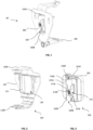
- Figure 1 illustrates a bracket 50 made up of a body 100 and a securing element 200.
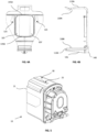
- Figures 2 and 3 illustrate the body 100 and securing element 200 in greater detail.
- the body 100 has a back plate 105, a first finger 110A and a second finger 110B.
- the first 110A and second 110B fingers extend from opposed ends of the same side of the back plate 105 and are arranged to secure a pump 10 (see also Figure 5 ) to a structure, such as a rod 55 (see Figure 8 ) by engaging opposed surfaces of the pump.
- a raised section 115 on the same side of the back plate 105 defines a cavity 120 into which the securing element 200 can be inserted.
- the securing element 200 has a base 205, a first boss 210A and a second boss 210B spaced apart from one another.
- the base 205 has ridges 225A, 225B on opposed ends of the base 205 (see Figure 6A ) that engage with corresponding edges 103A, 103B of the back plate 105.
- the raised section 115 also has ridges 145A, 145B on opposed ends thereof that engage with corresponding edges 207A, 207B of the base 205.
- the ridges 145A, 145B, 225A and 225B act as mechanical snap-fit joints to secure the securing element 200 within the cavity 120 of body 100.
- a user can simply press the appropriate securing element 200 into the cavity 120 and audible feedback from the engagement of the ridges 145, 225 confirms that the securing element 200 is secured to the body 100.
- the back plate 105 has a window 109 through which the bosses 210A, 210B of the securing element 200 pass through and protrude from.
- the pump 10 is preferably located on the side of the back plate 105 having the raised section 115, as this further helps to prevent separation of the securing element 200 from the body 100. In certain embodiments, therefore, the snap-fit connection between the securing element and the body 100 could be omitted.
- the window 109 is smaller than the cavity 120, which results in portions 107 of the back plate 105 extending across the cavity 120 to act as a mechanical stop defining how far the bosses project beyond the back plate and retaining the securing element within the cavity 120.
- the two fingers 110A, 110B extend from the back plate 105 in a substantially perpendicular direction to a plane defined by the back plate 105.
- the first finger 110A extends from the top of the back plate and has a protrusion 130A configured to engage with a corresponding groove 25 in a upper side 20 of a housing 15 of the pump 10 (see Figures 5 and 8 ).
- the second finger 110B extends from the bottom of the back plate 105 and has a protrusion 130B configured to engage with a corresponding groove (not shown) in the underside of the pump housing 15.
- the fingers 110A, 110B are configured to engage opposed sides of the housing 15 when the protrusions 130A, 130B are located within the respective grooves 25 in the housing 15.
- first 110A and second 110B fingers are preferably resiliently deformable, this allows for some deflection of the fingers 110A, 110B to accommodate the pump 10 as it is pressed towards the back plate 105.
- the fingers 110A, 110B deflect back towards their original position as their respective protrusions 130A, 130B are received by grooves 25 in the pump housing 15 to securely hold the pump in the bracket.
- first finger 130A has been bent to provide the protrusion 130A of the first finger 110A, it would be apparent this was not essential, and that a substantially straight finger having a protrusion thereon would be adequate to engage with the housing 15.
- the upwardly canted distal end of the first finger 130A provides a convenient surface for a user to urge the first finger 130A away from the second finger 130B in order to release the pump from the bracket.
- the fingers 110A, 110B are shown having protrusions, it would be apparent this was not essential, and that the fingers 110A, 110B may each have a groove configured to receive corresponding protrusions on the housing 15 in order to provide the engagement between the housing 15 and the fingers 110A, 110B.
- the ends of the fingers 110A, 110B may simply be angled such that the end-most points of the fingers 110A, 110B are received within grooves 25 in the housing 15.
- the body 100 also has a supporting rib 135 extending underneath the second finger 110B.
- the supporting rib 135 is provided to stiffen the second finger 110B, as the second finger 100B will act as a platform, bearing the majority of the weight of the pump 10 when secured in the bracket 50.
- An anti-vibration mount 140 is also provided on a lower portion of the side plate 105 adjacent to where the second finger 110B connects to the side plate 105.
- the anti-vibration mount 140 is positioned between the contact point of the bracket 50 and the rod 55 or wall to which it is mounted, so that transmissions primarily pass through the anti-vibration mount 140 to reach the wall or rod 55.
- the anti-vibration mount 140 is preferably made of a thermoplastic elastomeric material.
- the back plate 105 has two mounting holes 125 to provide flexibility to mount the bracket 50 to a wall instead of the rod 55, in which case the securing element 200 would not be clipped into place in the body.
- the first boss 210A and second boss 210B each have a respective end surface 212A, 212B (see Figure 3 ) which, in combination, define a gap 215 into which the rod 55 can be inserted (see Figure 7A ).
- the first boss 210A has a first core 220A and the second boss 210B has a second core 220B, and both cores 220A, 220B are sized to receive the rod 55 (see Figure 7B ).
- the cores 220A, 220B of the first 210A and second 210B bosses define a channel 222 through which the rod 55 passes when the securing element 200 is secured to the rod 55.
- the first boss 210A is formed of a substantially tubular body having a pair wings 230A and the second boss 210B is formed of a substantially tubular body having a pair of wings 230B.
- the pairs of wings 230A, 230B are spaced to define respective slots 235A, 235B between the respective pairs of wings 230A, 230B.
- each slots 235A, 235B extends in a substantially parallel direction to a longitudinal axis of the respective core 220A, 220B, and the respective slots extend in opposite directions to one another.
- the gap 215 extends in a different direction to that of the channel 222.
- the direction of the gap 215 and the direction of the channel 222 form an acute angle.
- the wings 230A, 230B are also resiliently deformable and can be deflected to provide an opening through which the rod 55 can be inserted into the respective cores 220A, 220B. While the cross-sectional profile of the bosses 210A, 210B is shown as being substantially circular, it would be apparent this was not essential and the bosses 210A, 210B may have a non-circular cross-sectional profile.
- the channel 222 defined by the bosses can be advantageous for the channel 222 defined by the bosses to have a substantially matching circular cross-sectional profile so as to maximise the mutual surface engagement between the securing element 200 and the elongate member for a more secure grip.
- At least a portion 240 of the inner surface of the bosses 210A, 210B may be threaded, for engagement with a correspondingly threaded rod 55.
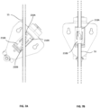
- Figures 7A and 7B illustrate a process by which the bracket 50 can be mounted to the rod 55.
- the assembled bracket 50 is pressed into a first position, angled relative to the rod 55 such that the rod 55 is located in the gap 215 between the bosses 210A, 210B.
- the bracket 50 can then be rotated to the second position relative to the rod 55 ( Figure 7B ) such that the rod 55 is secured within the channel 222.
- the rod 55 pushes the wings 230A, 230B apart and slides into the cores 220A, 220B.
- the wings 230A, 230B may each include a chamfered surface 231A, 231B to help stabilise the rod 55 on the wings 230A, 230B when rotating the bracket 50 from the first position to the second position.
- the resilience of the wings 230A, 230B allows the rod 55 to pass through the slots 235A, 235B as widened by a camming action against the chamfered surfaces 231A, 231B, with the wings returning to their original positions once the rod has passed through into the channel 222 to be gripped by the cores 220A, 22B, thus securing the bracket 50 to the rod 55.
- the rod 55 may have a cross-sectional area slightly larger than that of the cores 220A, 220B, so that the wings 230A, 230B will remain in a slightly separated configuration to ensure that the rod 55 is firmly gripped once it is in the channel 222.
- features on the internal surface of the bosses 210A, 210B may provide positive engagement with corresponding surface features on the rod 55 to enhance the grip of the bosses 210A, 210B on the rod 55.
- the bracket 50 can be rotated about a longitudinal axis of the rod 55 to secure the bracket 50 to the rod 55 in the second position.
- the threaded surface 240 of the boss and the threaded surface of the rod 55 act as a screw thread which allows for fine adjustment of the position of the bracket, ergo the pump 10 along the longitudinal axis of the rod 55.
- the user only needs to locate the bracket at roughly the correct position along the rod 55, before securing the bracket 50 and then mounting the pump 10 thereto. Once the pump 10 is mounted, the user can then make any fine adjustments to finalise the position of the bracket 50 without having to remove the bracket 50 from the rod 55.
- the user can also rotate the bracket 50, once the pump is mounted thereto, for example to accommodate liquid inlet tubes, liquid outlet tubes, power cables, sensor cables and any other accessories in the ceiling cavity that are connected to the pump 10.
- the user simply has to rotate the bracket 50 to locate the rod 55 in the gap 215 before pulling the bracket 50 free from the rod 55.
- the user need only separate the fingers 110A, 110B to release the pump 10. The user can then release the bracket 50 from the rod 55 in the manner described above.
- a rod 55 has been described as one example of an elongate structure that would be suitable for mounting the bracket 50 to, it would be apparent this was merely exemplary. In some cases, a separate mating bracket having a suitable elongate structure may be used instead of a ceiling rod. It would also be apparent that it is not essential for the rod to be linear, and that non-linear structures would also be suitable for use with the presently described bracket 50. Further, it would be apparent that while the cores 220A, 220B are preferably co-linear, it would be apparent that this was not essential and that the cores 220A, 220B may define a channel 222 having a non-linear path. This may be advantageous where the bracket 50 is to be mounted to a non-linear structure. Thus, the non-linear structure could still be received in the gap 215 between the bosses 210A, 210B and the bracket 50 rotated in the manner described above to secure the bracket 50 to the non-linear structure.
- the cores 220A, 220B can be considered to define a reference cross-sectional area. Structures having a cross-sectional area smaller than the reference cross-sectional area will not be gripped by the bosses 210A, 210B. Preferably, the structure should have a cross-sectional area slightly larger than the reference cross-sectional area for the reasons given above. Therefore, when the bracket 50 needs to be mounted to a ceiling wire or cable having a smaller cross-sectional area than the reference cross-sectional area, an adapter 300 (see Fig. 9 ) should be used to secure the bracket 50 to the ceiling wire.
- the adapter 300 has a body 302 and a core 304 (shown in phantom) configured to receive the wire and a slot 306 configured to allow the wire to pass through the body 302 of the adapter and into the core.
- the adapter 300 may include a head 308 that is wider than the body 302 to positively locate the adapter body in the associated core 220A, 220B.
- the adapter 300 is preferably made from an elastomeric material so the user is able to press the adapters around the wire before pressing an adapter into the core 220 of a respective boss 210. When the adapter 300 is pressed into the core 220, the resilience of the wings 230 will squeeze the adapter around the wire, thus securing the bracket 50 to the wire.
- the user only needs to use the body 100 of the bracket 50 to secure the pump 10 to the wall. This can be achieved, for example, via the mounting holes 125 formed in the back plate 105, which allows the user to screw the body 100 to the wall in the conventional manner.
- the pump 10 can then be secured to the body 100 in the manner described above.
- the body 100 can also function as a retrofittable bracket for use with existing devices and mounting points.
Landscapes
- Engineering & Computer Science (AREA)
- General Engineering & Computer Science (AREA)
- Mechanical Engineering (AREA)
- Architecture (AREA)
- Civil Engineering (AREA)
- Electromagnetism (AREA)
- Physics & Mathematics (AREA)
- Structural Engineering (AREA)
- Chemical & Material Sciences (AREA)
- Combustion & Propulsion (AREA)
- Details Of Reciprocating Pumps (AREA)
- Clamps And Clips (AREA)
- Structures Of Non-Positive Displacement Pumps (AREA)
Claims (15)
- Halterung (50) zum Befestigen einer Vorrichtung (10) an einer länglichen Struktur (55), die Halterung umfassend:einen Körper (100), der konfiguriert ist, um die Vorrichtung (10) zu halten, undein Befestigungselement (200), das an dem Körper angebracht ist,wobei das Befestigungselement (200) ein Paar von Vorsprüngen (210A, 210B) umfasst, jeder Vorsprung umfassend einen Schlitz (235A, 235B), einen Kern (220A, 220B) und eine Stirnfläche (212A, 212B),wobei die Vorsprünge (210A, 210B) an dem Befestigungselement (200) angeordnet sind, sodass die Stirnflächen (212A, 212B) einen Spalt (215) definieren, in den die längliche Struktur (55) aufgenommen werden kann, wenn das Befestigungselement in einer ersten Position in Bezug auf die längliche Struktur ist, und die Schlitze (235A, 235B) konfiguriert sind, um die längliche Struktur bei Drehung des Befestigungselements (200) aus der ersten Position in eine zweite Position in Bezug auf die längliche Struktur (55) aufzunehmen, undwodurch die Halterung (50) durch einen Greifeingriff zwischen der länglichen Struktur und den Vorsprüngen (210A, 210B) des Befestigungselements in der zweiten Position an der länglichen Struktur (55) befestigt ist,wobei der Körper (100) eine Rückplatte (105) und ein Paar von Fingern (110A, 110B) umfasst, die sich davon erstrecken, wobei das Paar von Fingern konfiguriert ist, um mit einem Paar von gegenüberliegenden Oberflächen der Vorrichtung (10) einzugreifen, um die Vorrichtung zu stützen, undwobei die Rückplatte (105) ferner einen erhöhten Abschnitt (115) aufweist, der einen Hohlraum (120) zum Aufnehmen des Befestigungselements (200) definiert, wobei das Befestigungselement ferner eine Basis (205) umfasst, und wobei die Basis (205) in einer installierten Konfiguration auf einer Seite der Rückplatte (105) in dem Hohlraum (120) befestigt ist und die Vorsprünge (210A, 210B) durch die Rückplatte hervorstehen und auf einer anderen Seite der Rückplatte (105) angeordnet sind.
- Halterung nach Anspruch 1, wobei sich der Spalt (215) in eine erste Richtung erstreckt, und wobei die jeweiligen Kerne (220A, 220B) einen Kanal (222) definieren, der sich in eine zweite Richtung erstreckt, die sich von der ersten Richtung unterscheidet.
- Halterung nach Anspruch 2, wobei der Winkel zwischen der ersten Richtung und der zweiten Richtung zwischen 45 Grad und 90 Grad ist.
- Halterung nach einem der vorhergehenden Ansprüche, wobei jeder Vorsprung (210A, 210B) ein elastisch verformbares Material umfasst.
- Halterung nach einem der vorhergehenden Ansprüche, wobei das Befestigungselement (200) lösbar an dem Körper (100) angebracht ist.
- Halterung nach einem der vorhergehenden Ansprüche, wobei die Rückplatte (105) mindestens ein Montageloch (125) zum Befestigen der Halterung (50) an einer Außenfläche umfasst.
- Halterung nach einem der vorhergehenden Ansprüche, wobei die jeweiligen Kerne (220A, 220B) der Vorsprünge (210A, 210B) kollinear sind.
- Halterung nach einem der vorhergehenden Ansprüche, wobei der Körper (100) ein elastisch verformbares Element (140) umfasst, das konfiguriert ist, um die Übertragung von Schwingungen zwischen der Struktur (55) und der Halterung zu reduzieren.
- Halterung nach Anspruch 8, wobei das elastisch verformbare Element (140) an einem unteren Abschnitt des Körpers (100) montiert ist.
- Halterung nach einem der vorhergehenden Ansprüche, ferner umfassend ein Paar von Adaptern (300), die konfiguriert sind, um die längliche Struktur (55) in einem jeweiligen Vorsprung (210A, 210B) zu befestigen, und wobei jeder der Adapter (300) bemessen ist, um in einen jeweiligen Vorsprung (210A, 210B) zu passen.
- Halterung nach Anspruch 10, wobei die Adapter (300) ein elastisch verformbares Material umfassen.
- Halterung nach Anspruch 10 oder 11, wobei jeder der Adapter (300) einen Schlitz (306) und einen Kern (304) umfasst, wobei der Kern (304) des Adapters konfiguriert ist, um die längliche Struktur (55) über den Schlitz (306) des Adapters aufzunehmen, wobei der Querschnitt des Kerns (304) größer ist als der Querschnitt der länglichen Struktur (55), und wobei jeder Vorsprung (210A, 210B) konfiguriert ist, um die längliche Struktur unter Verwendung des jeweiligen Adapters (300) zu greifen.
- Verfahren zum Montieren einer Halterung an einer länglichen Struktur, das Verfahren umfassend:Bereitstellen einer Halterung (50) nach einem der Ansprüche 1 bis 12,Drücken der Halterung (50) auf die Struktur (55), um die Struktur in dem Spalt (215) zu positionieren, undDrehen der Halterung (50), sodass die Struktur (55) durch die jeweiligen Schlitze (235A, 235B) und in die jeweiligen Kerne (220A, 220B) der Vorsprünge (210A, 210B) verläuft.
- Verfahren nach Anspruch 13, wenn abhängig von Anspruch 12, ferner umfassend:Bereitstellen eines Paars von Adaptern (300) nach Anspruch 12, undDrücken des Paars von Adaptern (300) gegen die Struktur (55), um die Struktur in dem jeweiligen Kern (304) der Adapter zu positionieren, bevor jeder der Adapter (300) in den Kern (220A, 220B) der jeweiligen Vorsprünge (210A, 210B) gedrückt wird.
- Verfahren nach Anspruch 13, wenn abhängig von Anspruch 12, ferner umfassend:Bereitstellen eines Paars von Adaptern (300) nach Anspruch 12, undDrücken eines Adapters (300) in den Kern (220A, 220B) von jedem Vorsprung (210A, 210B),wobei ein Drehen der Halterung (50) bewirkt, dass die Struktur (55) über den Schlitz (306) des jeweiligen Adapters (300) in den Kern (304) des jeweiligen Adapters (300) eintritt.
Applications Claiming Priority (2)
| Application Number | Priority Date | Filing Date | Title |
|---|---|---|---|
| GB2001238.1A GB2591477B (en) | 2020-01-29 | 2020-01-29 | A bracket for securing a device |
| PCT/GB2021/050023 WO2021152285A1 (en) | 2020-01-29 | 2021-01-05 | A bracket for securing a device |
Publications (2)
| Publication Number | Publication Date |
|---|---|
| EP4097358A1 EP4097358A1 (de) | 2022-12-07 |
| EP4097358B1 true EP4097358B1 (de) | 2024-02-07 |
Family
ID=69725910
Family Applications (1)
| Application Number | Title | Priority Date | Filing Date |
|---|---|---|---|
| EP21700064.5A Active EP4097358B1 (de) | 2020-01-29 | 2021-01-05 | Halterung zur befestigung einer vorrichtung |
Country Status (4)
| Country | Link |
|---|---|
| US (1) | US12078287B2 (de) |
| EP (1) | EP4097358B1 (de) |
| GB (1) | GB2591477B (de) |
| WO (1) | WO2021152285A1 (de) |
Families Citing this family (2)
| Publication number | Priority date | Publication date | Assignee | Title |
|---|---|---|---|---|
| US11781709B2 (en) * | 2019-08-19 | 2023-10-10 | Blue-White Industries, Ltd. | Quick-release pump mounting bracket |
| GB2614908B (en) * | 2022-01-24 | 2024-04-17 | Aspen Pumps Ltd | A condensate pump assembly |
Family Cites Families (17)
| Publication number | Priority date | Publication date | Assignee | Title |
|---|---|---|---|---|
| US2191782A (en) * | 1937-07-19 | 1940-02-27 | G A Goff | Thermometer holder |
| CA1110137A (en) * | 1976-05-24 | 1981-10-06 | Ingemar H. Lundquist | Intravenous liquid pumping system and method |
| DE7624077U1 (de) | 1976-07-29 | 1977-03-17 | Imed Corp., San Diego, Calif. (V.St.A.) | Volumetrische pumpe |
| US4315611A (en) * | 1978-07-05 | 1982-02-16 | Hoop James B | Device for suspending articles from a ceiling or the like |
| IL57311A (en) | 1979-05-16 | 1983-02-23 | Tadiran Israel Elect Ind Ltd | Alcohol trap for absorption chiller |
| US5024405A (en) * | 1989-05-12 | 1991-06-18 | Mcguire Robert H | Pipe clamp |
| US5351920A (en) * | 1993-04-09 | 1994-10-04 | Pipe Tytes, Inc. | Pipe support |
| GB9718247D0 (en) * | 1997-08-28 | 1997-11-05 | Phillips Raymond J | Support device |
| USD477770S1 (en) * | 2001-11-08 | 2003-07-29 | William E. Baker | Rotational snap action clamp |
| US7806583B2 (en) * | 2006-02-17 | 2010-10-05 | Fred Oswald | Clamping mechanism |
| US8091846B1 (en) * | 2008-10-14 | 2012-01-10 | John D Britner | Work supporting apparatus |
| KR20140058840A (ko) | 2012-11-07 | 2014-05-15 | 김경복 | 물체 부착용 행거 |
| US20160081505A1 (en) * | 2014-09-18 | 2016-03-24 | Donald Joseph Berg | Gyroscopic cup holder |
| USD759474S1 (en) * | 2015-03-19 | 2016-06-21 | Craig Allen Pittman | Hanger clip for stairway spindles and balusters |
| US10018216B1 (en) * | 2015-05-28 | 2018-07-10 | Cetres Holdings, Llc | Slotted nut for hold down threaded rods |
| US10926025B2 (en) | 2016-09-15 | 2021-02-23 | Tandem Diabetes Care, Inc. | Vial supporter for medicament pump |
| US10274110B1 (en) * | 2018-06-01 | 2019-04-30 | Hsiao-Han Liu | S-shaped locking fastener structure |
-
2020
- 2020-01-29 GB GB2001238.1A patent/GB2591477B/en active Active
-
2021
- 2021-01-05 US US17/796,459 patent/US12078287B2/en active Active
- 2021-01-05 WO PCT/GB2021/050023 patent/WO2021152285A1/en not_active Ceased
- 2021-01-05 EP EP21700064.5A patent/EP4097358B1/de active Active
Also Published As
| Publication number | Publication date |
|---|---|
| GB202001238D0 (en) | 2020-03-11 |
| WO2021152285A1 (en) | 2021-08-05 |
| GB2591477A (en) | 2021-08-04 |
| GB2591477B (en) | 2023-02-15 |
| US20230341083A1 (en) | 2023-10-26 |
| US12078287B2 (en) | 2024-09-03 |
| EP4097358A1 (de) | 2022-12-07 |
Similar Documents
| Publication | Publication Date | Title |
|---|---|---|
| EP2795140B1 (de) | Kabelbinderhalterung | |
| JP6768650B2 (ja) | チャンネルフレームのための継手 | |
| CN1328370A (zh) | 带有锁定夹子的电缆管道连接器 | |
| US7287734B2 (en) | Combination spring tension rod and mounting brackets for window coverings | |
| EP1007874A1 (de) | Stützvorrichtung aus kunststoff, insbesondere für rohre und kabel | |
| US12078287B2 (en) | Bracket for securing a device | |
| US20100133390A1 (en) | Variable Angle Fitting | |
| EP4160069B1 (de) | Kunststoffrohrschelle | |
| KR101832214B1 (ko) | 케이블 설치가 용이한 공동주택용 케이블트레이 | |
| EP0724318B1 (de) | Verbindungsdose für Deckenlüfter | |
| JP2009526961A (ja) | 圧迫インジケータ | |
| US6648278B1 (en) | Offset hanger | |
| US7130521B2 (en) | Cable guide | |
| US20260015859A1 (en) | Brace for ceiling drop | |
| EP4102663B1 (de) | Montageanordnung für elektrische sammelschiene | |
| KR101828043B1 (ko) | 케이블 트레이 | |
| KR100396594B1 (ko) | 천장 걸이용 디스플레이 장치의 고정 및 각도 조절장치 | |
| JPH0519671Y2 (de) | ||
| CN210858437U (zh) | 淋浴门板固定装置及淋浴门 | |
| US20260015876A1 (en) | Coupling elements and systems | |
| US20080080957A1 (en) | Sliding nut with captive screw | |
| CA2461255A1 (en) | Electrical box hanger | |
| EP3989377B1 (de) | Elektrische montagevorrichtung zur montage einer elektrischen installationsdose | |
| US20240275150A1 (en) | Mounting bracket for electrical box | |
| CN212407226U (zh) | 一种管道连接器、管道组件及用于显示装置的支撑装置 |
Legal Events
| Date | Code | Title | Description |
|---|---|---|---|
| STAA | Information on the status of an ep patent application or granted ep patent |
Free format text: STATUS: UNKNOWN |
|
| STAA | Information on the status of an ep patent application or granted ep patent |
Free format text: STATUS: THE INTERNATIONAL PUBLICATION HAS BEEN MADE |
|
| PUAI | Public reference made under article 153(3) epc to a published international application that has entered the european phase |
Free format text: ORIGINAL CODE: 0009012 |
|
| STAA | Information on the status of an ep patent application or granted ep patent |
Free format text: STATUS: REQUEST FOR EXAMINATION WAS MADE |
|
| 17P | Request for examination filed |
Effective date: 20220729 |
|
| AK | Designated contracting states |
Kind code of ref document: A1 Designated state(s): AL AT BE BG CH CY CZ DE DK EE ES FI FR GB GR HR HU IE IS IT LI LT LU LV MC MK MT NL NO PL PT RO RS SE SI SK SM TR |
|
| DAV | Request for validation of the european patent (deleted) | ||
| DAX | Request for extension of the european patent (deleted) | ||
| REG | Reference to a national code |
Ref country code: DE Ref legal event code: R079 Free format text: PREVIOUS MAIN CLASS: F04B0053160000 Ref country code: DE Ref legal event code: R079 Ref document number: 602021009216 Country of ref document: DE Free format text: PREVIOUS MAIN CLASS: F04B0053160000 Ipc: F16B0005060000 |
|
| GRAP | Despatch of communication of intention to grant a patent |
Free format text: ORIGINAL CODE: EPIDOSNIGR1 |
|
| STAA | Information on the status of an ep patent application or granted ep patent |
Free format text: STATUS: GRANT OF PATENT IS INTENDED |
|
| GRAS | Grant fee paid |
Free format text: ORIGINAL CODE: EPIDOSNIGR3 |
|
| RIC1 | Information provided on ipc code assigned before grant |
Ipc: F16B 21/07 20060101ALI20231115BHEP Ipc: F04B 53/22 20060101ALI20231115BHEP Ipc: F04B 53/16 20060101ALI20231115BHEP Ipc: F16B 5/06 20060101AFI20231115BHEP |
|
| INTG | Intention to grant announced |
Effective date: 20231207 |
|
| GRAA | (expected) grant |
Free format text: ORIGINAL CODE: 0009210 |
|
| STAA | Information on the status of an ep patent application or granted ep patent |
Free format text: STATUS: THE PATENT HAS BEEN GRANTED |
|
| AK | Designated contracting states |
Kind code of ref document: B1 Designated state(s): AL AT BE BG CH CY CZ DE DK EE ES FI FR GB GR HR HU IE IS IT LI LT LU LV MC MK MT NL NO PL PT RO RS SE SI SK SM TR |
|
| REG | Reference to a national code |
Ref country code: GB Ref legal event code: FG4D |
|
| REG | Reference to a national code |
Ref country code: CH Ref legal event code: EP |
|
| REG | Reference to a national code |
Ref country code: IE Ref legal event code: FG4D |
|
| REG | Reference to a national code |
Ref country code: DE Ref legal event code: R096 Ref document number: 602021009216 Country of ref document: DE |
|
| REG | Reference to a national code |
Ref country code: LT Ref legal event code: MG9D |
|
| REG | Reference to a national code |
Ref country code: NL Ref legal event code: MP Effective date: 20240207 |
|
| PG25 | Lapsed in a contracting state [announced via postgrant information from national office to epo] |
Ref country code: IS Free format text: LAPSE BECAUSE OF FAILURE TO SUBMIT A TRANSLATION OF THE DESCRIPTION OR TO PAY THE FEE WITHIN THE PRESCRIBED TIME-LIMIT Effective date: 20240607 |
|
| PG25 | Lapsed in a contracting state [announced via postgrant information from national office to epo] |
Ref country code: LT Free format text: LAPSE BECAUSE OF FAILURE TO SUBMIT A TRANSLATION OF THE DESCRIPTION OR TO PAY THE FEE WITHIN THE PRESCRIBED TIME-LIMIT Effective date: 20240207 |
|
| PG25 | Lapsed in a contracting state [announced via postgrant information from national office to epo] |
Ref country code: GR Free format text: LAPSE BECAUSE OF FAILURE TO SUBMIT A TRANSLATION OF THE DESCRIPTION OR TO PAY THE FEE WITHIN THE PRESCRIBED TIME-LIMIT Effective date: 20240508 |
|
| REG | Reference to a national code |
Ref country code: AT Ref legal event code: MK05 Ref document number: 1655553 Country of ref document: AT Kind code of ref document: T Effective date: 20240207 |
|
| PG25 | Lapsed in a contracting state [announced via postgrant information from national office to epo] |
Ref country code: RS Free format text: LAPSE BECAUSE OF FAILURE TO SUBMIT A TRANSLATION OF THE DESCRIPTION OR TO PAY THE FEE WITHIN THE PRESCRIBED TIME-LIMIT Effective date: 20240507 Ref country code: HR Free format text: LAPSE BECAUSE OF FAILURE TO SUBMIT A TRANSLATION OF THE DESCRIPTION OR TO PAY THE FEE WITHIN THE PRESCRIBED TIME-LIMIT Effective date: 20240207 Ref country code: NL Free format text: LAPSE BECAUSE OF FAILURE TO SUBMIT A TRANSLATION OF THE DESCRIPTION OR TO PAY THE FEE WITHIN THE PRESCRIBED TIME-LIMIT Effective date: 20240207 |
|
| PG25 | Lapsed in a contracting state [announced via postgrant information from national office to epo] |
Ref country code: ES Free format text: LAPSE BECAUSE OF FAILURE TO SUBMIT A TRANSLATION OF THE DESCRIPTION OR TO PAY THE FEE WITHIN THE PRESCRIBED TIME-LIMIT Effective date: 20240207 |
|
| PG25 | Lapsed in a contracting state [announced via postgrant information from national office to epo] |
Ref country code: AT Free format text: LAPSE BECAUSE OF FAILURE TO SUBMIT A TRANSLATION OF THE DESCRIPTION OR TO PAY THE FEE WITHIN THE PRESCRIBED TIME-LIMIT Effective date: 20240207 |
|
| PG25 | Lapsed in a contracting state [announced via postgrant information from national office to epo] |
Ref country code: RS Free format text: LAPSE BECAUSE OF FAILURE TO SUBMIT A TRANSLATION OF THE DESCRIPTION OR TO PAY THE FEE WITHIN THE PRESCRIBED TIME-LIMIT Effective date: 20240507 Ref country code: NO Free format text: LAPSE BECAUSE OF FAILURE TO SUBMIT A TRANSLATION OF THE DESCRIPTION OR TO PAY THE FEE WITHIN THE PRESCRIBED TIME-LIMIT Effective date: 20240507 Ref country code: NL Free format text: LAPSE BECAUSE OF FAILURE TO SUBMIT A TRANSLATION OF THE DESCRIPTION OR TO PAY THE FEE WITHIN THE PRESCRIBED TIME-LIMIT Effective date: 20240207 Ref country code: LT Free format text: LAPSE BECAUSE OF FAILURE TO SUBMIT A TRANSLATION OF THE DESCRIPTION OR TO PAY THE FEE WITHIN THE PRESCRIBED TIME-LIMIT Effective date: 20240207 Ref country code: IS Free format text: LAPSE BECAUSE OF FAILURE TO SUBMIT A TRANSLATION OF THE DESCRIPTION OR TO PAY THE FEE WITHIN THE PRESCRIBED TIME-LIMIT Effective date: 20240607 Ref country code: HR Free format text: LAPSE BECAUSE OF FAILURE TO SUBMIT A TRANSLATION OF THE DESCRIPTION OR TO PAY THE FEE WITHIN THE PRESCRIBED TIME-LIMIT Effective date: 20240207 Ref country code: GR Free format text: LAPSE BECAUSE OF FAILURE TO SUBMIT A TRANSLATION OF THE DESCRIPTION OR TO PAY THE FEE WITHIN THE PRESCRIBED TIME-LIMIT Effective date: 20240508 Ref country code: FI Free format text: LAPSE BECAUSE OF FAILURE TO SUBMIT A TRANSLATION OF THE DESCRIPTION OR TO PAY THE FEE WITHIN THE PRESCRIBED TIME-LIMIT Effective date: 20240207 Ref country code: ES Free format text: LAPSE BECAUSE OF FAILURE TO SUBMIT A TRANSLATION OF THE DESCRIPTION OR TO PAY THE FEE WITHIN THE PRESCRIBED TIME-LIMIT Effective date: 20240207 Ref country code: BG Free format text: LAPSE BECAUSE OF FAILURE TO SUBMIT A TRANSLATION OF THE DESCRIPTION OR TO PAY THE FEE WITHIN THE PRESCRIBED TIME-LIMIT Effective date: 20240207 Ref country code: AT Free format text: LAPSE BECAUSE OF FAILURE TO SUBMIT A TRANSLATION OF THE DESCRIPTION OR TO PAY THE FEE WITHIN THE PRESCRIBED TIME-LIMIT Effective date: 20240207 |
|
| PG25 | Lapsed in a contracting state [announced via postgrant information from national office to epo] |
Ref country code: PL Free format text: LAPSE BECAUSE OF FAILURE TO SUBMIT A TRANSLATION OF THE DESCRIPTION OR TO PAY THE FEE WITHIN THE PRESCRIBED TIME-LIMIT Effective date: 20240207 Ref country code: PT Free format text: LAPSE BECAUSE OF FAILURE TO SUBMIT A TRANSLATION OF THE DESCRIPTION OR TO PAY THE FEE WITHIN THE PRESCRIBED TIME-LIMIT Effective date: 20240607 |
|
| PG25 | Lapsed in a contracting state [announced via postgrant information from national office to epo] |
Ref country code: SE Free format text: LAPSE BECAUSE OF FAILURE TO SUBMIT A TRANSLATION OF THE DESCRIPTION OR TO PAY THE FEE WITHIN THE PRESCRIBED TIME-LIMIT Effective date: 20240207 Ref country code: PT Free format text: LAPSE BECAUSE OF FAILURE TO SUBMIT A TRANSLATION OF THE DESCRIPTION OR TO PAY THE FEE WITHIN THE PRESCRIBED TIME-LIMIT Effective date: 20240607 Ref country code: PL Free format text: LAPSE BECAUSE OF FAILURE TO SUBMIT A TRANSLATION OF THE DESCRIPTION OR TO PAY THE FEE WITHIN THE PRESCRIBED TIME-LIMIT Effective date: 20240207 Ref country code: LV Free format text: LAPSE BECAUSE OF FAILURE TO SUBMIT A TRANSLATION OF THE DESCRIPTION OR TO PAY THE FEE WITHIN THE PRESCRIBED TIME-LIMIT Effective date: 20240207 |
|
| PG25 | Lapsed in a contracting state [announced via postgrant information from national office to epo] |
Ref country code: DK Free format text: LAPSE BECAUSE OF FAILURE TO SUBMIT A TRANSLATION OF THE DESCRIPTION OR TO PAY THE FEE WITHIN THE PRESCRIBED TIME-LIMIT Effective date: 20240207 |
|
| PG25 | Lapsed in a contracting state [announced via postgrant information from national office to epo] |
Ref country code: SM Free format text: LAPSE BECAUSE OF FAILURE TO SUBMIT A TRANSLATION OF THE DESCRIPTION OR TO PAY THE FEE WITHIN THE PRESCRIBED TIME-LIMIT Effective date: 20240207 |
|
| PG25 | Lapsed in a contracting state [announced via postgrant information from national office to epo] |
Ref country code: EE Free format text: LAPSE BECAUSE OF FAILURE TO SUBMIT A TRANSLATION OF THE DESCRIPTION OR TO PAY THE FEE WITHIN THE PRESCRIBED TIME-LIMIT Effective date: 20240207 Ref country code: CZ Free format text: LAPSE BECAUSE OF FAILURE TO SUBMIT A TRANSLATION OF THE DESCRIPTION OR TO PAY THE FEE WITHIN THE PRESCRIBED TIME-LIMIT Effective date: 20240207 |
|
| PG25 | Lapsed in a contracting state [announced via postgrant information from national office to epo] |
Ref country code: SK Free format text: LAPSE BECAUSE OF FAILURE TO SUBMIT A TRANSLATION OF THE DESCRIPTION OR TO PAY THE FEE WITHIN THE PRESCRIBED TIME-LIMIT Effective date: 20240207 |
|
| PG25 | Lapsed in a contracting state [announced via postgrant information from national office to epo] |
Ref country code: SM Free format text: LAPSE BECAUSE OF FAILURE TO SUBMIT A TRANSLATION OF THE DESCRIPTION OR TO PAY THE FEE WITHIN THE PRESCRIBED TIME-LIMIT Effective date: 20240207 Ref country code: SK Free format text: LAPSE BECAUSE OF FAILURE TO SUBMIT A TRANSLATION OF THE DESCRIPTION OR TO PAY THE FEE WITHIN THE PRESCRIBED TIME-LIMIT Effective date: 20240207 Ref country code: RO Free format text: LAPSE BECAUSE OF FAILURE TO SUBMIT A TRANSLATION OF THE DESCRIPTION OR TO PAY THE FEE WITHIN THE PRESCRIBED TIME-LIMIT Effective date: 20240207 Ref country code: EE Free format text: LAPSE BECAUSE OF FAILURE TO SUBMIT A TRANSLATION OF THE DESCRIPTION OR TO PAY THE FEE WITHIN THE PRESCRIBED TIME-LIMIT Effective date: 20240207 Ref country code: DK Free format text: LAPSE BECAUSE OF FAILURE TO SUBMIT A TRANSLATION OF THE DESCRIPTION OR TO PAY THE FEE WITHIN THE PRESCRIBED TIME-LIMIT Effective date: 20240207 Ref country code: CZ Free format text: LAPSE BECAUSE OF FAILURE TO SUBMIT A TRANSLATION OF THE DESCRIPTION OR TO PAY THE FEE WITHIN THE PRESCRIBED TIME-LIMIT Effective date: 20240207 |
|
| REG | Reference to a national code |
Ref country code: DE Ref legal event code: R097 Ref document number: 602021009216 Country of ref document: DE |
|
| PLBE | No opposition filed within time limit |
Free format text: ORIGINAL CODE: 0009261 |
|
| STAA | Information on the status of an ep patent application or granted ep patent |
Free format text: STATUS: NO OPPOSITION FILED WITHIN TIME LIMIT |
|
| 26N | No opposition filed |
Effective date: 20241108 |
|
| PG25 | Lapsed in a contracting state [announced via postgrant information from national office to epo] |
Ref country code: SI Free format text: LAPSE BECAUSE OF FAILURE TO SUBMIT A TRANSLATION OF THE DESCRIPTION OR TO PAY THE FEE WITHIN THE PRESCRIBED TIME-LIMIT Effective date: 20240207 |
|
| REG | Reference to a national code |
Ref country code: CH Ref legal event code: PL |
|
| PG25 | Lapsed in a contracting state [announced via postgrant information from national office to epo] |
Ref country code: MC Free format text: LAPSE BECAUSE OF FAILURE TO SUBMIT A TRANSLATION OF THE DESCRIPTION OR TO PAY THE FEE WITHIN THE PRESCRIBED TIME-LIMIT Effective date: 20240207 Ref country code: LU Free format text: LAPSE BECAUSE OF NON-PAYMENT OF DUE FEES Effective date: 20250105 |
|
| PG25 | Lapsed in a contracting state [announced via postgrant information from national office to epo] |
Ref country code: BE Free format text: LAPSE BECAUSE OF NON-PAYMENT OF DUE FEES Effective date: 20250131 |
|
| PG25 | Lapsed in a contracting state [announced via postgrant information from national office to epo] |
Ref country code: CH Free format text: LAPSE BECAUSE OF NON-PAYMENT OF DUE FEES Effective date: 20250131 |
|
| REG | Reference to a national code |
Ref country code: BE Ref legal event code: MM Effective date: 20250131 |
|
| PGFP | Annual fee paid to national office [announced via postgrant information from national office to epo] |
Ref country code: GB Payment date: 20251217 Year of fee payment: 6 |
|
| PG25 | Lapsed in a contracting state [announced via postgrant information from national office to epo] |
Ref country code: IT Free format text: LAPSE BECAUSE OF NON-PAYMENT OF DUE FEES Effective date: 20250105 |
|
| PG25 | Lapsed in a contracting state [announced via postgrant information from national office to epo] |
Ref country code: IE Free format text: LAPSE BECAUSE OF NON-PAYMENT OF DUE FEES Effective date: 20250105 |
|
| PGFP | Annual fee paid to national office [announced via postgrant information from national office to epo] |
Ref country code: DE Payment date: 20260107 Year of fee payment: 6 |
|
| PGFP | Annual fee paid to national office [announced via postgrant information from national office to epo] |
Ref country code: FR Payment date: 20260106 Year of fee payment: 6 |