EP4097331B1 - Steuerung des bohrbetriebsablaufs - Google Patents
Steuerung des bohrbetriebsablaufs Download PDFInfo
- Publication number
- EP4097331B1 EP4097331B1 EP21747892.4A EP21747892A EP4097331B1 EP 4097331 B1 EP4097331 B1 EP 4097331B1 EP 21747892 A EP21747892 A EP 21747892A EP 4097331 B1 EP4097331 B1 EP 4097331B1
- Authority
- EP
- European Patent Office
- Prior art keywords
- drilling
- data
- bit
- drillstring
- borehole
- Prior art date
- Legal status (The legal status is an assumption and is not a legal conclusion. Google has not performed a legal analysis and makes no representation as to the accuracy of the status listed.)
- Active
Links
Images


Classifications
-
- E—FIXED CONSTRUCTIONS
- E21—EARTH OR ROCK DRILLING; MINING
- E21B—EARTH OR ROCK DRILLING; OBTAINING OIL, GAS, WATER, SOLUBLE OR MELTABLE MATERIALS OR A SLURRY OF MINERALS FROM WELLS
- E21B7/00—Special methods or apparatus for drilling
- E21B7/04—Directional drilling
- E21B7/06—Deflecting the direction of boreholes
- E21B7/067—Deflecting the direction of boreholes with means for locking sections of a pipe or of a guide for a shaft in angular relation, e.g. adjustable bent sub
-
- E—FIXED CONSTRUCTIONS
- E21—EARTH OR ROCK DRILLING; MINING
- E21B—EARTH OR ROCK DRILLING; OBTAINING OIL, GAS, WATER, SOLUBLE OR MELTABLE MATERIALS OR A SLURRY OF MINERALS FROM WELLS
- E21B47/00—Survey of boreholes or wells
- E21B47/02—Determining slope or direction
- E21B47/022—Determining slope or direction of the borehole, e.g. using geomagnetism
-
- E—FIXED CONSTRUCTIONS
- E21—EARTH OR ROCK DRILLING; MINING
- E21B—EARTH OR ROCK DRILLING; OBTAINING OIL, GAS, WATER, SOLUBLE OR MELTABLE MATERIALS OR A SLURRY OF MINERALS FROM WELLS
- E21B44/00—Automatic control systems specially adapted for drilling operations, i.e. self-operating systems which function to carry out or modify a drilling operation without intervention of a human operator, e.g. computer-controlled drilling systems; Systems specially adapted for monitoring a plurality of drilling variables or conditions
-
- E—FIXED CONSTRUCTIONS
- E21—EARTH OR ROCK DRILLING; MINING
- E21B—EARTH OR ROCK DRILLING; OBTAINING OIL, GAS, WATER, SOLUBLE OR MELTABLE MATERIALS OR A SLURRY OF MINERALS FROM WELLS
- E21B7/00—Special methods or apparatus for drilling
- E21B7/04—Directional drilling
-
- E—FIXED CONSTRUCTIONS
- E21—EARTH OR ROCK DRILLING; MINING
- E21B—EARTH OR ROCK DRILLING; OBTAINING OIL, GAS, WATER, SOLUBLE OR MELTABLE MATERIALS OR A SLURRY OF MINERALS FROM WELLS
- E21B2200/00—Special features related to earth drilling for obtaining oil, gas or water
- E21B2200/20—Computer models or simulations, e.g. for reservoirs under production, drill bits
Definitions
- a resource field can be an accumulation, pool or group of pools of one or more resources (e.g., oil, gas, oil and gas) in a subsurface environment.
- a resource field can include at least one reservoir.
- a reservoir may be shaped in a manner that can trap hydrocarbons and may be covered by an impermeable or sealing rock.
- a bore e.g., a borehole
- a bore can be drilled into an environment where the bore may be utilized to form a well that can be utilized in producing hydrocarbons from a reservoir.
- a rig can be a system of components that can be operated to form a bore in an environment, to transport equipment into and out of a bore in an environment, etc.
- a rig can include a system that can be used to drill a bore and to acquire information about an environment, about drilling, etc.
- a resource field may be an onshore field, an offshore field or an on- and offshore field.
- a rig can include components for performing operations onshore and/or offshore.
- a rig may be, for example, vessel-based, offshore platform-based, onshore, etc.
- a method can include receiving data for a borehole trajectory in a formation, a length of pipe, and a bottom hole assembly that includes a mud motor and a bit; receiving a mode transition limit; generating a sequence for operation of the mud motor using a model of at least the bit, wherein the model comprises a physics-based model that represents interaction between the bit and the formation using a numerical computation technique, where the sequence includes a sliding mode and a rotary mode for drilling the borehole in the formation a distance less than or equal to the length of pipe, wherein the mode transition limit is less than five mode transitions; and drilling the borehole according to the sequence using the bottom hole assembly that comprises the mud motor and the bit.
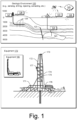
- Fig. 1 shows an example of a geologic environment 120.
- the geologic environment 120 may be a sedimentary basin that includes layers (e.g., stratification) that include a reservoir 121 and that may be, for example, intersected by a fault 123 (e.g., or faults).
- the geologic environment 120 may be outfitted with any of a variety of sensors, detectors, actuators, etc.
- equipment 122 may include communication circuitry to receive and to transmit information with respect to one or more networks 125.
- Such information may include information associated with downhole equipment 124, which may be equipment to acquire information, to assist with resource recovery, etc.
- Other equipment 126 may be located remote from a well site and include sensing, detecting, emitting or other circuitry. Such equipment may include storage and communication circuitry to store and to communicate data, instructions, etc. As an example, one or more pieces of equipment may provide for measurement, collection, communication, storage, analysis, etc. of data (e.g., for one or more produced resources, etc.). As an example, one or more satellites may be provided for purposes of communications, data acquisition, etc. For example, Fig. 1 shows a satellite in communication with the network 125 that may be configured for communications, noting that the satellite may additionally or alternatively include circuitry for imagery (e.g., spatial, spectral, temporal, radiometric, etc.).
- imagery e.g., spatial, spectral, temporal, radiometric, etc.
- Fig. 1 also shows the geologic environment 120 as optionally including equipment 127 and 128 associated with a well that includes a substantially horizontal portion (e.g., a lateral portion) that may intersect with one or more fractures 129.
- a well in a shale formation may include natural fractures, artificial fractures (e.g., hydraulic fractures) or a combination of natural and artificial fractures.
- a well may be drilled for a reservoir that is laterally extensive.
- lateral variations in properties, stresses, etc. may exist where an assessment of such variations may assist with planning, operations, etc. to develop the reservoir (e.g., via fracturing, injecting, extracting, etc.).
- the equipment 127 and/or 128 may include components, a system, systems, etc. for fracturing, seismic sensing, analysis of seismic data, assessment of one or more fractures, injection, production, etc.
- the equipment 127 and/or 128 may provide for measurement, collection, communication, storage, analysis, etc. of data such as, for example, production data (e.g., for one or more produced resources).
- production data e.g., for one or more produced resources
- one or more satellites may be provided for purposes of communications, data acquisition, etc.
- Fig. 1 also shows an example of equipment 170 and an example of equipment 180.
- equipment which may be systems of components, may be suitable for use in the geologic environment 120. While the equipment 170 and 180 are illustrated as land-based, various components may be suitable for use in an offshore system (e.g., an offshore rig, etc.).
- an offshore system e.g., an offshore rig, etc.
- the equipment 170 includes a platform 171, a derrick 172, a crown block 173, a line 174, a traveling block assembly 175, drawworks 176 and a landing 177 (e.g., a monkeyboard).
- the line 174 may be controlled at least in part via the drawworks 176 such that the traveling block assembly 175 travels in a vertical direction with respect to the platform 171.
- the drawworks 176 may cause the line 174 to run through the crown block173 and lift the traveling block assembly 175 skyward away from the platform 171; whereas, by allowing the line 174 out, the drawworks 176 may cause the line 174 to run through the crown block 173 and lower the traveling block assembly 175 toward the platform 171.
- the traveling block assembly 175 carries pipe (e.g., casing, etc.)
- tracking of movement of the traveling block 175 may provide an indication as to how much pipe has been deployed.
- a derrick can be a structure used to support a crown block and a traveling block operatively coupled to the crown block at least in part via line.
- a derrick may be pyramidal in shape and offer a suitable strength-to-weight ratio.
- a derrick may be movable as a unit or in a piece by piece manner (e.g., to be assembled and disassembled).
- drawworks may include a spool, brakes, a power source and assorted auxiliary devices.
- Drawworks may controllably reel out and reel in line.
- Line may be reeled over a crown block and coupled to a traveling block to gain mechanical advantage in a "block and tackle” or “pulley” fashion.
- Reeling out and in of line can cause a traveling block (e.g., and whatever may be hanging underneath it), to be lowered into or raised out of a bore.
- Reeling out of line may be powered by gravity and reeling in by a motor, an engine, etc. (e.g., an electric motor, a diesel engine, etc.).
- a crown block can include a set of pulleys (e.g., sheaves) that can be located at or near a top of a derrick or a mast, over which line is threaded.
- a traveling block can include a set of sheaves that can be moved up and down in a derrick or a mast via line threaded in the set of sheaves of the traveling block and in the set of sheaves of a crown block.
- a crown block, a traveling block and a line can form a pulley system of a derrick or a mast, which may enable handling of heavy loads (e.g., drillstring, pipe, casing, liners, etc.) to be lifted out of or lowered into a bore.
- line may be about a centimeter to about five centimeters in diameter as, for example, steel cable. Through use of a set of sheaves, such line may carry loads heavier than the line could support as a single strand.
- a derrickman may be a rig crew member that works on a platform attached to a derrick or a mast.
- a derrick can include a landing on which a derrickman may stand.
- a landing may be about 10 meters or more above a rig floor.
- a derrickman may wear a safety harness that enables leaning out from the work landing (e.g., monkeyboard) to reach pipe located at or near the center of a derrick or a mast and to throw a line around the pipe and pull it back into its storage location (e.g., fingerboards), for example, until it may be desirable to run the pipe back into the bore.
- a rig may include automated pipe-handling equipment such that the derrickman controls the machinery rather than physically handling the pipe.
- a trip may refer to the act of pulling equipment from a bore and/or placing equipment in a bore.
- equipment may include a drillstring that can be pulled out of a hole and/or placed or replaced in a hole.
- a pipe trip may be performed where a drill bit has dulled or has otherwise ceased to drill efficiently and is to be replaced.
- a trip that pulls equipment out of a borehole may be referred to as pulling out of hole (POOH) and a trip that runs equipment into a borehole may be referred to as running in hole (RIH).
- POOH pulling out of hole
- RHIH running in hole
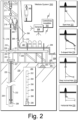
- Fig. 2 shows an example of a wellsite system 200 (e.g., at a wellsite that may be onshore or offshore).
- the wellsite system 200 can include a mud tank 201 for holding mud and other material (e.g., where mud can be a drilling fluid), a suction line 203 that serves as an inlet to a mud pump 204 for pumping mud from the mud tank 201 such that mud flows to a vibrating hose 206, a drawworks 207 for winching drill line or drill lines 212, a standpipe 208 that receives mud from the vibrating hose 206, a kelly hose 209 that receives mud from the standpipe 208, a gooseneck or goosenecks 210, a traveling block 211, a crown block 213 for carrying the traveling block 211 via the drill line or drill lines 212 (see, e.g., the crown block 173 of Fig.
- a derrick 214 (see, e.g., the derrick 172 of Fig. 1 ), a kelly 218 or a top drive 240, a kelly drive bushing 219, a rotary table 220, a drill floor 221, a bell nipple 222, one or more blowout preventors (BOPs) 223, a drillstring 225, a drill bit 226, a casing head 227 and a flow pipe 228 that carries mud and other material to, for example, the mud tank 201.
- BOPs blowout preventors
- a borehole 232 is formed in subsurface formations 230 by rotary drilling; noting that various example embodiments may also use one or more directional drilling techniques, equipment, etc.
- the drillstring 225 is suspended within the borehole 232 and has a drillstring assembly 250 that includes the drill bit 226 at its lower end.
- the drillstring assembly 250 may be a bottom hole assembly (BHA).
- the wellsite system 200 can provide for operation of the drillstring 225 and other operations. As shown, the wellsite system 200 includes the traveling block 211 and the derrick 214 positioned over the borehole 232. As mentioned, the wellsite system 200 can include the rotary table 220 where the drillstring 225 pass through an opening in the rotary table 220.
- the wellsite system 200 can include the kelly 218 and associated components, etc., or a top drive 240 and associated components.
- the kelly 218 may be a square or hexagonal metal/alloy bar with a hole drilled therein that serves as a mud flow path.
- the kelly 218 can be used to transmit rotary motion from the rotary table 220 via the kelly drive bushing 219 to the drillstring 225, while allowing the drillstring 225 to be lowered or raised during rotation.
- the kelly 218 can pass through the kelly drive bushing 219, which can be driven by the rotary table 220.
- the top drive 240 can provide functions performed by a kelly and a rotary table.
- the top drive 240 can turn the drillstring 225.
- the top drive 240 can include one or more motors (e.g., electric and/or hydraulic) connected with appropriate gearing to a short section of pipe called a quill, that in turn may be screwed into a saver sub or the drillstring 225 itself.
- the top drive 240 can be suspended from the traveling block 211, so the rotary mechanism is free to travel up and down the derrick 214.
- a top drive 240 may allow for drilling to be performed with more joint stands than a kelly/rotary table approach.
- the mud tank 201 can hold mud, which can be one or more types of drilling fluids.
- mud can be one or more types of drilling fluids.
- a wellbore may be drilled to produce fluid, inject fluid or both (e.g., hydrocarbons, minerals, water, etc.).
- the drillstring 225 (e.g., including one or more downhole tools) may be composed of a series of pipes threadably connected together to form a long tube with the drill bit 226 at the lower end thereof.
- the mud may be pumped by the pump 204 from the mud tank 201 (e.g., or other source) via a the lines 206, 208 and 209 to a port of the kelly 218 or, for example, to a port of the top drive 240.
- the mud can then flow via a passage (e.g., or passages) in the drillstring 225 and out of ports located on the drill bit 226 (see, e.g., a directional arrow).
- a passage e.g., or passages
- the mud can then circulate upwardly through an annular region between an outer surface(s) of the drillstring 225 and surrounding wall(s) (e.g., open borehole, casing, etc.), as indicated by directional arrows.
- Directional drilling involves drilling into the Earth to form a deviated bore such that the trajectory of the bore is not vertical; rather, the trajectory deviates from vertical along one or more portions of the bore.
- drilling can commence with a vertical portion and then deviate from vertical such that the bore is aimed at the target and, eventually, reaches the target.
- the LWD module 254 may be housed in a suitable type of drill collar and can contain one or a plurality of selected types of logging tools. It will also be understood that more than one LWD and/or MWD module can be employed, for example, as represented at by the module 256 of the drillstring assembly 250. Where the position of an LWD module is mentioned, as an example, it may refer to a module at the position of the LWD module 254, the module 256, etc.
- An LWD module can include capabilities for measuring, processing, and storing information, as well as for communicating with the surface equipment. In the illustrated example, the LWD module 254 may include a seismic measuring device.
- a directional well can include several shapes where each of the shapes may aim to meet particular operational demands.
- a drilling process may be performed on the basis of information as and when it is relayed to a drilling engineer.
- inclination and/or direction may be modified based on information received during a drilling process.
- a system may be a steerable system and include equipment to perform method such as geosteering.
- a steerable system can be or include an RSS.
- a steerable system can include a PDM or of a turbine on a lower part of a drillstring which, just above a drill bit, a bent sub can be mounted.
- MWD equipment that provides real time or near real time data of interest (e.g., inclination, direction, pressure, temperature, real weight on the drill bit, torque stress, etc.) and/or LWD equipment may be installed.
- LWD equipment can make it possible to send to the surface various types of data of interest, including for example, geological data (e.g., gamma ray log, resistivity, density and sonic logs, etc.).
- a drillstring can include an azimuthal density neutron (ADN) tool for measuring density and porosity; a MWD tool for measuring inclination, azimuth and shocks; a compensated dual resistivity (CDR) tool for measuring resistivity and gamma ray related phenomena; one or more variable gauge stabilizers; one or more bend joints; and a geosteering tool, which may include a motor and optionally equipment for measuring and/or responding to one or more of inclination, resistivity and gamma ray related phenomena.
- ADN azimuthal density neutron
- MWD for measuring inclination, azimuth and shocks
- CDR compensated dual resistivity
- geosteering can include intentional directional control of a wellbore based on results of downhole geological logging measurements in a manner that aims to keep a directional wellbore within a desired region, zone (e.g., a pay zone), etc.
- geosteering may include directing a wellbore to keep the wellbore in a particular section of a reservoir, for example, to minimize gas and/or water breakthrough and, for example, to maximize economic production from a well that includes the wellbore.
- the wellsite system 200 can include one or more sensors 264 that are operatively coupled to the control and/or data acquisition system 262.
- a sensor or sensors may be at surface locations.
- a sensor or sensors may be at downhole locations.
- a sensor or sensors may be at one or more remote locations that are not within a distance of the order of about one hundred meters from the wellsite system 200.
- a sensor or sensor may be at an offset wellsite where the wellsite system 200 and the offset wellsite are in a common field (e.g., oil and/or gas field).
- one or more of the sensors 264 can be provided for tracking pipe, tracking movement of at least a portion of a drillstring, etc.
- the system 200 can include one or more sensors 266 that can sense and/or transmit signals to a fluid conduit such as a drilling fluid conduit (e.g., a drilling mud conduit).
- a fluid conduit such as a drilling fluid conduit (e.g., a drilling mud conduit).
- the one or more sensors 266 can be operatively coupled to portions of the standpipe 208 through which mud flows.
- a downhole tool can generate pulses that can travel through the mud and be sensed by one or more of the one or more sensors 266.
- the downhole tool can include associated circuitry such as, for example, encoding circuitry that can encode signals, for example, to reduce demands as to transmission.
- circuitry at the surface may include decoding circuitry to decode encoded information transmitted at least in part via mud-pulse telemetry.
- circuitry at the surface may include encoder circuitry and/or decoder circuitry and circuitry downhole may include encoder circuitry and/or decoder circuitry.
- the system 200 can include a transmitter that can generate signals that can be transmitted downhole via mud (e.g., drilling fluid) as a transmission medium.
- mud e.g., drilling fluid
- stuck can refer to one or more of varying degrees of inability to move or remove a drillstring from a bore.
- a stuck condition it might be possible to rotate pipe or lower it back into a bore or, for example, in a stuck condition, there may be an inability to move the drillstring axially in the bore, though some amount of rotation may be possible.
- a stuck condition there may be an inability to move at least a portion of the drillstring axially and rotationally.
- stuck pipe this can refer to a portion of a drillstring that cannot be rotated or moved axially.
- a condition referred to as “differential sticking” can be a condition whereby the drillstring cannot be moved (e.g., rotated or reciprocated) along the axis of the bore. Differential sticking may occur when high-contact forces caused by low reservoir pressures, high wellbore pressures, or both, are exerted over a sufficiently large area of the drillstring. Differential sticking can have time and financial cost.
- a sticking force can be a product of the differential pressure between the wellbore and the reservoir and the area that the differential pressure is acting upon. This means that a relatively low differential pressure (delta p) applied over a large working area can be just as effective in sticking pipe as can a high differential pressure applied over a small area.
- a condition referred to as "mechanical sticking” can be a condition where limiting or prevention of motion of the drillstring by a mechanism other than differential pressure sticking occurs.
- Mechanical sticking can be caused, for example, by one or more of junk in the hole, wellbore geometry anomalies, cement, keyseats or a buildup of cuttings in the annulus.
- Fig. 3 shows an example of a system 300 that includes various equipment for evaluation 310, planning 320, engineering 330 and operations 340.
- a drilling workflow framework 301, a seismic-to-simulation framework 302, a technical data framework 303 and a drilling framework 304 may be implemented to perform one or more processes such as a evaluating a formation 314, evaluating a process 318, generating a trajectory 324, validating a trajectory 328, formulating constraints 334, designing equipment and/or processes based at least in part on constraints 338, performing drilling 344 and evaluating drilling and/or formation 348.
- the seismic-to-simulation framework 302 can be, for example, the PETREL framework (Schlumberger, Houston, Texas) and the technical data framework 303 can be, for example, the TECHLOG framework (Schlumberger, Houston, Texas).
- a framework can include entities that may include earth entities, geological objects or other objects such as wells, surfaces, reservoirs, etc. Entities can include virtual representations of actual physical entities that are reconstructed for purposes of one or more of evaluation, planning, engineering, operations, etc.
- Entities may include entities based on data acquired via sensing, observation, etc. (e.g., seismic data and/or other information).
- An entity may be characterized by one or more properties (e.g., a geometrical pillar grid entity of an earth model may be characterized by a porosity property).
- properties may represent one or more measurements (e.g., acquired data), calculations, etc.
- a framework may be an object-based framework.
- entities may include entities based on pre-defined classes, for example, to facilitate modeling, analysis, simulation, etc.
- An example of an object-based framework is the MICROSOFT .NET framework (Redmond, Washington), which provides a set of extensible object classes.
- .NET framework an object class encapsulates a module of reusable code and associated data structures.
- Object classes can be used to instantiate object instances for use in by a program, script, etc.
- borehole classes may define objects for representing boreholes based on well data.
- a framework may be implemented within or in a manner operatively coupled to the DELFI cognitive exploration and production (E&P) environment (Schlumberger, Houston, Texas), which is a secure, cognitive, cloud-based collaborative environment that integrates data and workflows with digital technologies, such as artificial intelligence and machine learning.
- E&P DELFI cognitive exploration and production
- such an environment can provide for operations that involve one or more frameworks.
- a framework can include an analysis component that may allow for interaction with a model or model-based results (e.g., simulation results, etc.).
- a framework may operatively link to or include a simulator such as the ECLIPSE reservoir simulator (Schlumberger, Houston Texas), the INTERSECT reservoir simulator (Schlumberger, Houston Texas), etc.
- the aforementioned PETREL framework provides components that allow for optimization of exploration and development operations.
- the PETREL framework includes seismic to simulation software components that can output information for use in increasing reservoir performance, for example, by improving asset team productivity.
- various professionals e.g., geophysicists, geologists, well engineers, reservoir engineers, etc.
- Such a framework may be considered an application and may be considered a data-driven application (e.g., where data is input for purposes of modeling, simulating, etc.).
- one or more frameworks may be interoperative and/or run upon one or another.
- a framework environment marketed as the OCEAN framework environment (Schlumberger, Houston, Texas) may be utilized, which allows for integration of add-ons (or plug-ins) into a PETREL framework workflow.
- various components may be implemented as add-ons (or plug-ins) that conform to and operate according to specifications of a framework environment (e.g., according to application programming interface (API) specifications, etc.).
- API application programming interface
- a framework can include a model simulation layer along with a framework services layer, a framework core layer and a modules layer.
- a model simulation layer can include or operatively link to a model-centric framework.
- a framework may be considered to be a data-driven application.
- the PETREL framework can include features for model building and visualization.
- a model may include one or more grids where a grid can be a spatial grid that conforms to spatial locations per acquired data (e.g., satellite data, logging data, seismic data, etc.).
- a model simulation layer may provide domain objects, act as a data source, provide for rendering and provide for various user interfaces.
- Rendering capabilities may provide a graphical environment in which applications can display their data while user interfaces may provide a common look and feel for application user interface components.
- domain objects can include entity objects, property objects and optionally other objects.
- Entity objects may be used to geometrically represent wells, surfaces, reservoirs, etc.
- property objects may be used to provide property values as well as data versions and display parameters.
- an entity object may represent a well where a property object provides log information as well as version information and display information (e.g., to display the well as part of a model).
- data may be stored in one or more data sources (or data stores, generally physical data storage devices), which may be at the same or different physical sites and accessible via one or more networks.
- a model simulation layer may be configured to model projects.
- a particular project may be stored where stored project information may include inputs, models, results and cases.
- a user may store a project.
- the project can be accessed and restored using the model simulation layer, which can recreate instances of the relevant domain objects.
- the system 300 may be used to perform one or more workflows.
- a workflow may be a process that includes a number of worksteps.
- a workstep may operate on data, for example, to create new data, to update existing data, etc.
- a workflow may operate on one or more inputs and create one or more results, for example, based on one or more algorithms.
- a system may include a workflow editor for creation, editing, executing, etc. of a workflow. In such an example, the workflow editor may provide for selection of one or more pre-defined worksteps, one or more customized worksteps, etc.
- a workflow may be a workflow implementable at least in part in the PETREL framework, for example, that operates on seismic data, seismic attribute(s), etc.
- seismic data can be data acquired via a seismic survey where sources and receivers are positioned in a geologic environment to emit and receive seismic energy where at least a portion of such energy can reflect off subsurface structures.
- a seismic data analysis framework or frameworks e.g., consider the OMEGA framework, marketed by Schlumberger, Houston, Texas
- seismic data analysis can include forward modeling and/or inversion, for example, to iteratively build a model of a subsurface region of a geologic environment.
- a seismic data analysis framework may be part of or operatively coupled to a seismic-to-simulation framework (e.g., the PETREL framework, etc.).
- a workflow may be a process implementable at least in part in a framework environment and by one or more frameworks.
- a workflow may include one or more worksteps that access a set of instructions such as a plug-in (e.g., external executable code, etc.).
- a framework environment may be cloud-based where cloud resources are utilized that may be operatively coupled to one or more pieces of field equipment such that data can be acquired, transmitted, stored, processed, analyzed, etc., using features of a framework environment.
- a framework environment may employ various types of services, which may be backend, frontend or backend and frontend services. For example, consider a client-server type of architecture where communications may occur via one or more application programming interfaces (APIs), one or more microservices, etc.
- APIs application programming interfaces
- a framework may provide for modeling petroleum systems.
- the modeling framework marketed as the PETROMOD framework (Schlumberger, Houston, Texas), which includes features for input of various types of information (e.g., seismic, well, geological, etc.) to model evolution of a sedimentary basin.
- the PETROMOD framework provides for petroleum systems modeling via input of various data such as seismic data, well data and other geological data, for example, to model evolution of a sedimentary basin.
- the PETROMOD framework may predict if, and how, a reservoir has been charged with hydrocarbons, including, for example, the source and timing of hydrocarbon generation, migration routes, quantities, pore pressure and hydrocarbon type in the subsurface or at surface conditions.
- workflows may be constructed to provide basin-to-prospect scale exploration solutions.
- Data exchange between frameworks can facilitate construction of models, analysis of data (e.g., PETROMOD framework data analyzed using PETREL framework capabilities), and coupling of workflows.
- a drillstring can include various tools that may make measurements.
- a wireline tool or another type of tool may be utilized to make measurements.
- a tool may be configured to acquire electrical borehole images.
- the fullbore Formation Microlmager (FMI) tool (Schlumberger, Houston, Texas) can acquire borehole image data.
- a data acquisition sequence for such a tool can include running the tool into a borehole with acquisition pads closed, opening and pressing the pads against a wall of the borehole, delivering electrical current into the material defining the borehole while translating the tool in the borehole, and sensing current remotely, which is altered by interactions with the material.
- Analysis of formation information may reveal features such as, for example, vugs, dissolution planes (e.g., dissolution along bedding planes), stress-related features, dip events, etc.
- a tool may acquire information that may help to characterize a reservoir, optionally a fractured reservoir where fractures may be natural and/or artificial (e.g., hydraulic fractures).
- information acquired by a tool or tools may be analyzed using a framework such as the TECHLOG framework.
- the TECHLOG framework can be interoperable with one or more other frameworks such as, for example, the PETREL framework.
- a workflow may be cyclic, and may include, as an example, four stages such as, for example, an evaluation stage (see, e.g., the evaluation equipment 310), a planning stage (see, e.g., the planning equipment 320), an engineering stage (see, e.g., the engineering equipment 330) and an execution stage (see, e.g., the operations equipment 340).
- a workflow may commence at one or more stages, which may progress to one or more other stages (e.g., in a serial manner, in a parallel manner, in a cyclical manner, etc.).
- a workflow can commence with an evaluation stage, which may include a geological service provider evaluating a formation (see, e.g., the evaluation block 314).
- a geological service provider may undertake the formation evaluation using a computing system executing a software package tailored to such activity; or, for example, one or more other suitable geology platforms may be employed (e.g., alternatively or additionally).
- the geological service provider may evaluate the formation, for example, using earth models, geophysical models, basin models, petrotechnical models, combinations thereof, and/or the like.
- Such models may take into consideration a variety of different inputs, including offset well data, seismic data, pilot well data, other geologic data, etc.
- the models and/or the input may be stored in the database maintained by the server and accessed by the geological service provider.
- a workflow may progress to a geology and geophysics (“G&G”) service provider, which may generate a well trajectory (see, e.g., the generation block 324), which may involve execution of one or more G&G software packages.
- G&G software packages include the PETREL framework.
- a G&G service provider may determine a well trajectory or a section thereof, based on, for example, one or more model(s) provided by a formation evaluation (e.g., per the evaluation block 314), and/or other data, e.g., as accessed from one or more databases (e.g., maintained by one or more servers, etc.).
- a well trajectory may take into consideration various "basis of design” (BOD) constraints, such as general surface location, target (e.g., reservoir) location, and the like.
- BOD basic surface location
- target e.g., reservoir
- a trajectory may incorporate information about tools, bottom-hole assemblies, casing sizes, etc., that may be used in drilling the well.
- a well trajectory determination may take into consideration a variety of other parameters, including risk tolerances, fluid weights and/or plans, bottom-hole pressures, drilling time, etc.
- a workflow may progress to a first engineering service provider (e.g., one or more processing machines associated therewith), which may validate a well trajectory and, for example, relief well design (see, e.g., the validation block 328).
- a validation process may include evaluating physical properties, calculations, risk tolerances, integration with other aspects of a workflow, etc.
- one or more parameters for such determinations may be maintained by a server and/or by the first engineering service provider; noting that one or more model(s), well trajectory(ies), etc. may be maintained by a server and accessed by the first engineering service provider.
- the first engineering service provider may include one or more computing systems executing one or more software packages.
- the well trajectory may be adjusted or a message or other notification sent to the G&G service provider requesting such modification.
- one or more engineering service providers may provide a casing design, bottom-hole assembly (BHA) design, fluid design, and/or the like, to implement a well trajectory (see, e.g., the design block 338).
- BHA bottom-hole assembly
- a second engineering service provider may perform such design using one of more software applications.
- Such designs may be stored in one or more databases maintained by one or more servers, which may, for example, employ STUDIO framework tools (Schlumberger, Houston, Texas), and may be accessed by one or more of the other service providers in a workflow.
- a second engineering service provider may seek approval from a third engineering service provider for one or more designs established along with a well trajectory.
- the third engineering service provider may consider various factors as to whether the well engineering plan is acceptable, such as economic variables (e.g., oil production forecasts, costs per barrel, risk, drill time, etc.), and may request authorization for expenditure, such as from the operating company's representative, well-owner's representative, or the like (see, e.g., the formulation block 334).
- at least some of the data upon which such determinations are based may be stored in one or more database maintained by one or more servers.
- a first, a second, and/or a third engineering service provider may be provided by a single team of engineers or even a single engineer, and thus may or may not be separate entities.
- an engineering service provider may suggest changes to casing, a bottom-hole assembly, and/or fluid design, or otherwise notify and/or return control to a different engineering service provider, so that adjustments may be made to casing, a bottom-hole assembly, and/or fluid design.
- the engineering service provider may suggest an adjustment to the well trajectory and/or a workflow may return to or otherwise notify an initial engineering service provider and/or a G&G service provider such that either or both may modify the well trajectory.
- a workflow can include considering a well trajectory, including an accepted well engineering plan, and a formation evaluation. Such a workflow may then pass control to a drilling service provider, which may implement the well engineering plan, establishing safe and efficient drilling, maintaining well integrity, and reporting progress as well as operating parameters (see, e.g., the blocks 344 and 348). As an example, operating parameters, formation encountered, data collected while drilling (e.g., using logging-while-drilling or measuring-while-drilling technology), may be returned to a geological service provider for evaluation.
- the geological service provider may then re-evaluate the well trajectory, or one or more other aspects of the well engineering plan, and may, in some cases, and potentially within predetermined constraints, adjust the well engineering plan according to the real-life drilling parameters (e.g., based on acquired data in the field, etc.).
- a workflow may proceed to a post review (see, e.g., the evaluation block 318).
- a post review may include reviewing drilling performance.
- a post review may further include reporting the drilling performance (e.g., to one or more relevant engineering, geological, or G&G service providers).
- Various activities of a workflow may be performed consecutively and/or may be performed out of order (e.g., based partially on information from templates, nearby wells, etc. to fill in any gaps in information that is to be provided by another service provider).
- undertaking one activity may affect the results or basis for another activity, and thus may, either manually or automatically, call for a variation in one or more workflow activities, work products, etc.
- a server may allow for storing information on a central database accessible to various service providers where variations may be sought by communication with an appropriate service provider, may be made automatically, or may otherwise appear as suggestions to the relevant service provider.
- Such an approach may be considered to be a holistic approach to a well workflow, in comparison to a sequential, piecemeal approach.
- various actions of a workflow may be repeated multiple times during drilling of a wellbore.
- feedback from a drilling service provider may be provided at or near real-time, and the data acquired during drilling may be fed to one or more other service providers, which may adjust its piece of the workflow accordingly.
- such adjustments may permeate through the workflow, e.g., in an automated fashion.
- a cyclic process may additionally or instead proceed after a certain drilling goal is reached, such as the completion of a section of the wellbore, and/or after the drilling of the entire wellbore, or on a per-day, week, month, etc. basis.
- Well planning can include determining a path of a well (e.g., a trajectory) that can extend to a reservoir, for example, to economically produce fluids such as hydrocarbons therefrom.
- Well planning can include selecting a drilling and/or completion assembly which may be used to implement a well plan.
- various constraints can be imposed as part of well planning that can impact design of a well.
- such constraints may be imposed based at least in part on information as to known geology of a subterranean domain, presence of one or more other wells (e.g., actual and/or planned, etc.) in an area (e.g., consider collision avoidance), etc.
- one or more constraints may be imposed based at least in part on characteristics of one or more tools, components, etc.
- one or more constraints may be based at least in part on factors associated with drilling time and/or risk tolerance.
- a system can allow for a reduction in waste, for example, as may be defined according to LEAN.
- LEAN consider one or more of the following types of waste: transport (e.g., moving items unnecessarily, whether physical or data); inventory (e.g., components, whether physical or informational, as work in process, and finished product not being processed); motion (e.g., people or equipment moving or walking unnecessarily to perform desired processing); waiting (e.g., waiting for information, interruptions of production during shift change, etc.); overproduction (e.g., production of material, information, equipment, etc.
- transport e.g., moving items unnecessarily, whether physical or data
- inventory e.g., components, whether physical or informational, as work in process, and finished product not being processed
- motion e.g., people or equipment moving or walking unnecessarily to perform desired processing
- waiting e.g., waiting for information, interruptions of production during shift change, etc.
- a system that allows for actions (e.g., methods, workflows, etc.) to be performed in a collaborative manner can help to reduce one or more types of waste.
- a system can be utilized to implement a method for facilitating distributed well engineering, planning, and/or drilling system design across multiple computation devices where collaboration can occur among various different users (e.g., some being local, some being remote, some being mobile, etc.).
- the various users via appropriate devices may be operatively coupled via one or more networks (e.g., local and/or wide area networks, public and/or private networks, land-based, marine-based and/or areal networks, etc.).
- networks e.g., local and/or wide area networks, public and/or private networks, land-based, marine-based and/or areal networks, etc.
- a system may allow well engineering, planning, and/or drilling system design to take place via a subsystems approach where a wellsite system (e.g., a rigsite system) is composed of various subsystem, which can include equipment subsystems and/or operational subsystems (e.g., control subsystems, etc.).
- computations may be performed using various computational platforms/devices that are operatively coupled via communication links (e.g., network links, etc.).
- one or more links may be operatively coupled to a common database (e.g., a server site, etc.).
- a particular server or servers may manage receipt of notifications from one or more devices and/or issuance of notifications to one or more devices.
- a system may be implemented for a project where the system can output a well plan, for example, as a digital well plan, a paper well plan, a digital and paper well plan, etc.
- a well plan can be a complete well engineering plan or design for the particular project.
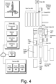
- Fig. 4 shows an example of a wellsite system 400, specifically, Fig. 4 shows the wellsite system 400 in an approximate side view and an approximate plan view along with a block diagram of a system 470.
- the wellsite system 400 can include a cabin 410, a rotary table 422, drawworks 424, a mast 426 (e.g., optionally carrying a top drive, etc.), mud tanks 430 (e.g., with one or more pumps, one or more shakers, etc.), one or more pump buildings 440, a boiler building 442, an HPU building 444 (e.g., with a rig fuel tank, etc.), a combination building 448 (e.g., with one or more generators, etc.), pipe tubs 462, a catwalk 464, a flare 468, etc.
- Such equipment can include one or more associated functions and/or one or more associated operational risks, which may be risks as to time, resources, and/or humans.
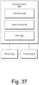
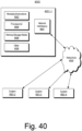
- the wellsite system 400 can include a system 470 that includes one or more processors 472, memory 474 operatively coupled to at least one of the one or more processors 472, instructions 476 that can be, for example, stored in the memory 474, and one or more interfaces 478.
- the system 470 can include one or more processor-readable media that include processor-executable instructions executable by at least one of the one or more processors 472 to cause the system 470 to control one or more aspects of the wellsite system 400.
- the memory 474 can be or include the one or more processor-readable media where the processor-executable instructions can be or include instructions.
- a processor-readable medium can be a computer-readable storage medium that is not a signal and that is not a carrier wave.
- Fig. 4 also shows a battery 480 that may be operatively coupled to the system 470, for example, to power the system 470.
- the battery 480 may be a back-up battery that operates when another power supply is unavailable for powering the system 470.
- the battery 480 may be operatively coupled to a network, which may be a cloud network.
- the battery 480 can include smart battery circuitry and may be operatively coupled to one or more pieces of equipment via a SMBus or other type of bus.
- services 490 are shown as being available, for example, via a cloud platform.
- Such services can include data services 492, query services 494 and drilling services 496.
- the services 490 may be part of a system such as the system 300 of Fig. 3 .
- system 470 may be utilized to generate one or more sequences and/or to receive one or more sequences, which may, for example, be utilized to control one or more drilling operations. For example, consider a sequence that includes a sliding mode and a drilling mode and a transition therebetween.
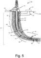
- Fig. 5 shows a schematic diagram depicting an example of a drilling operation of a directional well in multiple sections.
- the drilling operation depicted in Fig. 5 includes a wellsite drilling system 500 and a field management tool 520 for managing various operations associated with drilling a bore hole 550 of a directional well 517.
- the wellsite drilling system 500 includes various components (e.g., drillstring 512, annulus 513, bottom hole assembly (BHA) 514, kelly 515, mud pit 516, etc.).
- BHA bottom hole assembly
- a target reservoir may be located away from (as opposed to directly under) the surface location of the well 517.
- special tools or techniques may be used to ensure that the path along the bore hole 550 reaches the particular location of the target reservoir.
- the BHA 514 may include sensors 508, a rotary steerable system (RSS) 509, and a bit 510 to direct the drilling toward the target guided by a pre-determined survey program for measuring location details in the well.
- the subterranean formation through which the directional well 517 is drilled may include multiple layers (not shown) with varying compositions, geophysical characteristics, and geological conditions. Both the drilling planning during the well design stage and the actual drilling according to the drilling plan in the drilling stage may be performed in multiple sections (see, e.g., sections 501, 502, 503 and 504), which may correspond to one or more of the multiple layers in the subterranean formation. For example, certain sections (e.g., sections 501 and 502) may use cement 507 reinforced casing 506 due to the particular formation compositions, geophysical characteristics, and geological conditions.
- a surface unit 511 may be operatively linked to the wellsite drilling system 500 and the field management tool 520 via communication links 518.
- the surface unit 511 may be configured with functionalities to control and monitor the drilling activities by sections in real time via the communication links 518.
- the field management tool 520 may be configured with functionalities to store oilfield data (e.g., historical data, actual data, surface data, subsurface data, equipment data, geological data, geophysical data, target data, anti-target data, etc.) and determine relevant factors for configuring a drilling model and generating a drilling plan.
- the oilfield data, the drilling model, and the drilling plan may be transmitted via the communication link 518 according to a drilling operation workflow.
- the communication links 518 may include a communication subassembly.
- data can be acquired for analysis and/or monitoring of one or more operations.
- Such data may include, for example, subterranean formation, equipment, historical and/or other data.
- Static data can relate to, for example, formation structure and geological stratigraphy that define the geological structures of the subterranean formation.
- Static data may also include data about a bore, such as inside diameters, outside diameters, and depths.
- Dynamic data can relate to, for example, fluids flowing through the geologic structures of the subterranean formation over time.
- the dynamic data may include, for example, pressures, fluid compositions (e.g. gas oil ratio, water cut, and/or other fluid compositional information), and states of various equipment, and other information.
- the static and dynamic data collected via a bore, a formation, equipment, etc. may be used to create and/or update a three dimensional model of one or more subsurface formations.
- static and dynamic data from one or more other bores, fields, etc. may be used to create and/or update a three dimensional model.
- hardware sensors, core sampling, and well logging techniques may be used to collect data.
- static measurements may be gathered using downhole measurements, such as core sampling and well logging techniques.
- Well logging involves deployment of a downhole tool into the wellbore to collect various downhole measurements, such as density, resistivity, etc., at various depths.
- Such well logging may be performed using, for example, a drilling tool and/or a wireline tool, or sensors located on downhole production equipment.
- fluid may flow to the surface (e.g., and/or from the surface) using tubing and other completion equipment.
- various dynamic measurements such as fluid flow rates, pressure, and composition may be monitored. These parameters may be used to determine various characteristics of a subterranean formation, downhole equipment, downhole operations, etc.
- a system can include a framework that can acquire data such as, for example, real time data associated with one or more operations such as, for example, a drilling operation or drilling operations.
- a framework that can acquire data such as, for example, real time data associated with one or more operations such as, for example, a drilling operation or drilling operations.
- PERFORM toolkit framework Scholberger Limited, Houston, Texas.
- a service can be or include one or more of OPTIDRILL, OPTILOG and/or other services marketed by Schlumberger Limited, Houston, Texas.
- the OPTIDRILL technology can help to manage downhole conditions and BHA dynamics as a real time drilling intelligence service.
- the service can incorporate a rigsite display (e.g., a wellsite display) of integrated downhole and surface data that provides actionable information to mitigate risk and increase efficiency.
- a rigsite display e.g., a wellsite display
- data may be stored, for example, to a database system (e.g., consider a database system associated with the STUDIO framework).
- the OPTILOG technology can help to evaluate drilling system performance with single- or multiple-location measurements of drilling dynamics and internal temperature from a recorder.
- post-run data can be analyzed to provide input for future well planning.
- information from a drill bit database may be accessed and utilized.
- information from Smith Bits Schomberger Limited, Houston, Texas
- operations e.g., drilling operations
- one or more QTRAC services may be provided for one or more wellsite operations.
- data may be acquired and stored where such data can include time series data that may be received and analyzed, etc.
- M-I SWACO services may be provided for one or more wellsite operations.
- M-I L.L.C. Houston, Texas
- data may be acquired and stored where such data can include time series data that may be received and analyzed, etc.
- one or more ONE-TRAX services may be provided for one or more wellsite operations.
- data may be acquired and stored where such data can include time series data that may be received and analyzed, etc.
- WITS well-site information transfer specification or standard
- WITSML markup language
- WITS/WITSML specify how a drilling rig or offshore platform drilling rig can communicate data.
- WITS/WITSML define operations such as “bottom to slips” time as a time interval between coming off bottom and setting slips, for a current connection; “in slips” as a time interval between setting the slips and then releasing them, for a current connection; and “slips to bottom” as a time interval between releasing the slips and returning to bottom (e.g., setting weight on the bit), for a current connection.
- Well construction can occur according to various procedures, which can be in various forms.
- a procedure can be specified digitally and may be, for example, a digital plan such as a digital well plan.
- a digital well plan can be an engineering plan for constructing a wellbore.
- procedures can include information such as well geometries, casing programs, mud considerations, well control concerns, initial bit selections, offset well information, pore pressure estimations, economics and special procedures that may be utilized during the course of well construction, production, etc. While a drilling procedure can be carefully developed and specified, various conditions can occur that call for adjustment to a drilling procedure.
- An operator may be under one or more time constraints, which may be driven by physical phenomena, such as fluid flow, fluid pressure, compaction of rock, borehole stability, etc.
- decision making by the operator can depend on time as conditions evolve. For example, a decision made at one fluid pressure may be sub-optimal at another fluid pressure in an environment where fluid pressure is changing.
- timing as to implementing a decision as an adjustment to a procedure can have a broad ranging impact. An adjustment to a procedure that is made too late or too early can adversely impact other procedures compared to an adjustment to a procedure that is made at an optimal time (e.g., and implemented at the optimal time).
- drilling operations can be performed more efficiently, for example, with respect to time to drill a section, a portion of a section, an entire borehole, etc.
- equipment integrity e.g., health, etc.
- a mud motor can be utilized to drive a bit.
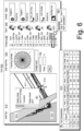
- Fig. 6 shows an example of a graphical user interface (GUI) 600 that includes information associated with a well plan.
- GUI graphical user interface
- the GUI 600 includes a panel 610 where surfaces representations 612 and 614 are rendered along with well trajectories where a location 616 can represent a position of a drillstring 617 along a well trajectory.
- the GUI 600 may include one or more editing features such as an edit well plan set of features 630.
- the GUI 600 may include information as to individuals of a team 640 that are involved, have been involved and/or are to be involved with one or more operations.
- the GUI 600 may include information as to one or more activities 650.
- the GUI 600 can include a graphical control of a drillstring 660 where, for example, various portions of the drillstring 660 may be selected to expose one or more associated parameters (e.g., type of equipment, equipment specifications, operational history, etc.).
- the drillstring graphical control 660 includes components such as drill pipe, heavy weight drill pipe (HWDP), subs, collars, jars, stabilizers, motor(s) and a bit.
- a drillstring can be a combination of drill pipe, a bottom hole assembly (BHA) and one or more other tools, which can include one or more tools that can help a drill bit turn and drill into material (e.g., a formation).
- a workflow can include utilizing the graphical control of the drillstring 660 to select and/or expose information associated with a component or components such as, for example, a bit and/or a mud motor.
- a computational framework e.g., via a sequence engine, etc.
- sequences which may be utilized, for example, to operating drilling equipment in a particular mode (e.g., sliding mode, rotating mode, etc.).
- a particular mode e.g., sliding mode, rotating mode, etc.
- a graphical control 665 is shown that can be rendered responsive to interaction with the graphical control of the drillstring 660, for example, to select a type of component and/or to generate one or more sequences, etc.
- another graphical control 667 is shown that can be rendered to a display with information as to drilling of a stand, which may be approximately 90 ft in length (e.g., approximately 30 m).
- the graphical control 667 shows use of a sliding mode for 30 ft (e.g., approcimaltely 10 m) of the stand with a toolface angle of 20 degrees and a transition from the sliding mode to a rotary mode where the rotary mode is utilized for the remaining 60 ft (e.g., approcimaltely 20 m) of the stand.
- a graphical control may be utilized during one or more phases such as, for example, during planning and/or during execution.
- a graphical control e.g., or GUI
- Fig. 6 also shows an example of a table 670 as a point spreadsheet that specifies information for a plurality of wells. As shown in the example table 670, coordinates such as "x" and "y” and “depth” can be specified for various features of the wells, which can include pad parameters, spacings, toe heights, step outs, initial inclinations, kick offs, etc.
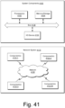
- Fig. 7 shows an example of a method 700 that utilizes drilling equipment to perform drilling operations.
- the drilling equipment includes a rig 701, a lift system 702, a block 703, a platform 704, slips 705 and a bottom hole assembly 706.
- the rig 701 supports the lift system 702, which provides for movement of the block 703 above the platform 704 where the slips 705 may be utilized to support a drillstring that includes the bottom hole assembly 706, which is shown as including a bit to drill into a formation to form a borehole.
- the drilling operations include a first operation 710 that completes a stand (Stand X) of the drillstring; a second operation 720 that pulls the drillstring off the bottom of the borehole by moving the block 703 upwardly and that supports the drillstring in the platform 704 using the slips 705; a third operation 730 that adds a stand (Stand X+1) to the drillstring; and a fourth operation 740 that removes the slips 705 and that lowers the drillstring to the bottom of the borehole by moving the block 703 downwardly.
- a first operation 710 that completes a stand (Stand X) of the drillstring
- a second operation 720 that pulls the drillstring off the bottom of the borehole by moving the block 703 upwardly and that supports the drillstring in the platform 704 using the slips 705
- a third operation 730 that adds a stand (Stand X+1) to the drillstring
- a fourth operation 740 that removes the slips 705 and that lowers the
- drilling operations may utilize one or more types of equipment to drill, which can provide for various modes of drilling.
- stands can be added to a drillstring.
- a stand can be one or more sections of pipe; noting that a pipe-by-pipe or hybrid stand and pipe approach may be utilized.
- the operations 710, 720, 730 and 740 may take a period of time that may be of the order of minutes. For example, consider the amount of time it takes to position and connect a stand to another stand of a drillstring. A stand may be approximately 30 meters in length where precautions are taken to avoid detrimental contacting of the stand (metal or metal alloy) with other equipment or humans. During the period of time, one or more types of calculations, computations, communications, etc., may occur. For example, a driller may perform a depth of hole calculation based on a measured length of a stand, etc. As an example, a driller may analyze survey data as acquired by one or more downhole tools of a drillstring. Such survey data may help a driller to determine whether or not a planned or otherwise desired trajectory is being followed, which may help to inform the driller as to how drilling is to occur for an increase in borehole depth corresponding approximately to the length of the added stand.
- top drive As an example, where a top drive is utilized (e.g., consider the block 703 as including a top drive), as the top drive approaches the platform 704, rotation and circulation can be stopped and the drillstring lifted a distance off the bottom of the borehole. As the top drive is to be coupled to another stand, it is to be disconnected, which means that the drillstring is to be supported, which can be accomplished through use of the slips 705.
- the slips 705 can be set on a portion of the last stand (e.g., a pipe) to support the weight of the drillstring such that the top drive can be disconnected from the drillstring by operator(s), for example, using a top drive pipehandler.
- the driller can then raise the top drive (e.g., the block 703) to an appropriate level such as a fingerboard level, where another stand of pipe (e.g., approximately 30 m) can be delivered to a set of drill pipe elevators hanging from the top drive.
- the stand e.g., Stand X+1
- the top drive can then be lowered until its drive stem engages an upper connection of the stand (e.g., Stand X+1).
- the top drive motor can be engaged to rotate the drive stem such that upper and lower connections of the stand are made up relatively simultaneously.
- a backup tong may be used at the platform 704 (e.g., drill floor) to prevent rotation of the drillstring as the connections are being made.
- the slips 705 can be released (e.g., out-of-slips).
- Circulation of drilling fluid e.g., mud
- the top drive can be utilized for drilling to deepen the borehole.
- the entire process, from the time the slips are set on the drillstring (e.g., in-slips), a new stand is added, the connections are made up, and the slips are released (e.g., out-of-slips), allowing drilling to resume, can take on the order of tens of seconds to minutes, generally less than 10 minutes where operations are normal and as expected.
- top drive approach the process of adding a new stand of pipe to the drillstring, and drilling down to the platform (e.g., the floor), can involve fewer actions and demand less involvement from a drill crew when compared to kelly drilling (e.g., rotary table drilling).
- Drillers and rig crews can become relatively proficient in drilling with top drives.
- Built-in features such as thread compensation, remote-controlled valves to stop the flow of drilling fluids, and mechanisms to tilt the elevators and links to the derrickman or floor crew can add to speed, convenience and safety associated with top drive drilling.
- a top drive can be utilized when drilling with single joints (e.g., 10 m lengths) of pipe, although greater benefit may be achieved by drilling with triples (e.g., stands of pipe where a stand can be approximately 30 m long).
- triples e.g., stands of pipe where a stand can be approximately 30 m long.
- an entire stand of drill pipe can be drilled down at one time.
- Such an approach can extend the time the bit is on bottom and can help to produce a cleaner borehole.
- top drive drilling can result in faster drilling by reducing demand for two out of three connections.
- a well can be a direction well, which is constructed using directional drilling.
- Directional wells have been a boon to oil and gas production, particularly in unconventional plays, where horizontal and extended-reach wells can help to maximize wellbore exposure through productive zones.
- One or more of various technologies can be utilized for directional drilling. For example, consider a steerable mud motor that can be utilized to achieve a desired borehole trajectory to and/or through one or more target zones. As an example, a directional drilling operation can use a downhole mud motor when they kick off the well, build angle, drill tangent sections and maintain trajectory.
- a mud motor can include a bend in a motor bearing housing that provides for steering a bit toward a desired target.
- a bend can be surface adjustable (e.g., a surface adjustable bend (SAB)) and, for example, set at an angle in a range of operational angles (e.g., consider 0 degrees to approximate 5 degrees, 0 degrees to approximately 4 degrees, 0 degrees to approximately 3 degrees, etc.).
- SAB surface adjustable bend
- the bend can aim to be sufficient for pointing the bit in a given direction while being small enough to permit rotation of the entire mud motor assembly during rotary drilling.
- the deflection cause by a bend can be a factor that determines a rate at which a mud motor can build angle to construct a desired borehole.
- a drilling operation can change the inclination and/or the azimuth of a borehole trajectory.
- the drillstring is operated in a sliding mode where the entire drillstring itself does not rotate in the borehole (e.g., via a top drive, a rotary table, etc.) and where bit rotation for drilling is driven by a mud motor of the drillstring.
- a mud motor is a type of positive displacement motor (PDM) powered by drilling fluid.
- a mud motor can include an eccentric helical rotor and stator assembly drive. As drilling fluid (e.g., mud) is pumped downhole, the drilling fluid flows through the stator and turns the rotor. The mud motor converts hydraulic power to mechanical power to turn a drive shaft that causes a bit operatively coupled to the mud motor to rotate.
- drilling fluid e.g., mud
- the mud motor converts hydraulic power to mechanical power to turn a drive shaft that causes a bit operatively coupled to the mud motor to rotate.
- a directional drilling operation can alternate between rotating and sliding modes of drilling.
- a rotating mode a rotary table or top drive is operated to rotate an entire drillstring to transmit power to a bit.
- the rotating mode can include combined rotation via surface equipment and via a downhole mud motor.
- rotation enables a bend in the motor bearing housing to be directed equally across directions and thus maintain a straight drilling path.
- MWD measurement-while-drilling
- Such measurements may be utilized to alert a driller, a controller, etc., to one or more deviations from a desired trajectory (e.g., a planned trajectory, etc.).
- a drilling operation can switch from the rotating mode to the sliding mode.
- the drillstring is not rotated; rather, a downhole motor turns the bit and the borehole is drilled in the direction the bit is point, which is controlled by toolface orientation.
- a drilling operation may transition from the sliding mode to the rotating mode, which, as mentioned, can be a combined surface and downhole rotating mode.
- the rate of penetration (ROP) achieved using a sliding technique tends to be approximately 10 percent to 25 percent of that attainable using a rotating technique.
- ROP rate of penetration
- axial drag force in a curve portion and/or in a lateral portion acts to reduce the impact of surface weight such that surface weight is not effectively transferred downhole to a bit, which can lead to a lower penetration rate and lower drilling efficiency.
- Various types of automated systems may aim to help a drilling operation to achieve gains in horizontal reach with noticeably faster rates of penetration.
- a drilling operation can halt rotation of a drillstring and initiate a slide by orienting a bit to drill, for example, in alignment with a trajectory proposed in a well plan.
- a drilling operation that pulls a bit off-bottom and reciprocates drillpipe to release torque that has built up within the drillstring.
- the drilling operation can then orient a downhole mud motor using real-time MWD toolface measurements to ensure the specified borehole deviation is obtained.
- the drilling operation can set a top drive brake to prevent further rotation from the surface.
- a slide can begin as the drilling operation eases off a drawworks brake to control hook load, which, in turn, affects the magnitude of weight imposed at the bit (e.g., WOB).
- minor right and left torque adjustments e.g., clockwise and counter-clockwise
- a drillstring tends to be subjected to greater friction and drag.
- These forces affect ability to transfer weight to the bit (e.g., WOB) and control toolface orientation while sliding, which may make it more difficult to attain sufficient ROP and maintain a desired trajectory to a target (or targets).
- WOB weight to the bit
- Such issues can result in increased drilling time, which may adversely impact project economics and ultimately limit length of a lateral section of a borehole and hence a lateral section of a completed well (e.g., a producing well).
- a drilling operation can transfers weight to a bit by easing, or slacking off, a brake, which can transfer some of the hook load, or drillstring weight, to the bit.
- the difference between the weight imposed at the bit and the amount of weight made available by easing the brake at the surface is primarily caused by drag. As a horizontal departure of a borehole increases, longitudinal drag of the drillpipe along the borehole tends to increase.
- a drilling operation can aim to operate a mud motor within a relatively narrow load range in an effort to maintain an acceptable ROP without stalling.
- a system can include a console, which can include one or more displays that can render one or more graphical user interfaces (GUIs) that include data from one or more sensors.
- GUIs graphical user interfaces
- an impending stall might be indicated by an increase in WOB as rendered to a GUI, for example, with no corresponding upsurge in downhole pressure to signal that an increase in downhole WOB has actually occurred.
- the WOB indicator may show an abrupt decrease, indicating a sudden transfer of force from the drillstring to the bit. Increases in drag impede an ability to remove torque downhole, making it more difficult to set and maintain toolface orientation.
- Reactive torque tends to build as weight is increased, for example, reaching its maximum value when a mud motor stalls.
- reactive torque can be taken into account as a drilling operation tries to orient a mud motor from the surface.
- a drilling operation may act to make minor shifts in toolface orientation by changing downhole WOB, which alters the reactive torque.
- the drilling operation may act to lift a bit off-bottom and reorient the toolface.
- longitudinal drag tends to increases with lateral reach, and weight transfer to the bit can become more erratic along the length of a horizontal section, thus allowing reactive torque to build and consequently change the toolface angle.
- the effort and time spent on orienting the toolface can adversely impact productive time on the rig.
- directional drilling can involve operating in the rotating mode and operating in the sliding mode where multiple transitions can be made between these two modes.
- drilling fluid can be utilized to drive a downhole mud motor and hence rotate a bit in a sliding mode
- surface equipment can be utilized to rotate an entire drillstring in a rotating mode (e.g., a rotary table, a top drive, etc.), optionally in combination with drilling fluid being utilized to drive a downhole mud motor (e.g., a combined rotating mode).
- Directional drilling operations can depend on various factors, including operational parameters that can be at least to some extent controllable. For example, one or more factors such as mode transitions, lifting, WOB, RPM, torque, and drilling fluid flow rate can be controllable during a drilling operation.
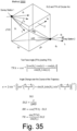
- the motor section 810 includes a dump valve 812, a power section 814, a surface-adjustable bent housing 816, a transmission assembly 818, a bearing section 820 and a drive shaft 822, which can be operatively coupled to a bit such as the bit 804.
- Flow of drilling fluid through the power section 814 can generate power that can rotate the drive shaft 822, which can rotate the bit 804.
- the power section 814 two examples are illustrated as a power section 814-1 and a power section 814-2 each of which includes a housing 842, a rotor 844 and a stator 846.
- the rotor 844 and the stator 846 can be characterized by a ratio.
- the power section 814-1 can be a 5:6 ratio and the power section 814-2 can be a 1:2 ratio, which, as seen in cross-sectional views, can involve lobes (e.g., a rotor/stator lobe configuration).
- the motor section 810 of Fig. 8 may be a POWERPAK family motor section (Schlumberger Limited, Houston, Texas) or another type of motor section.
- the POWERPAK family of motor sections can include ratios of 1:2, 2:3, 3:4, 4:5, 5:6 and 7:8 with corresponding lobe configurations.
- An elastomeric material can be formulated to resist abrasion and hydrocarbon induced deterioration.
- Various types of elastomeric materials may be utilized in a power section and some may be proprietary.
- Properties of an elastomeric material can be tailored for particular types of operations, which may consider factors such as temperature, speed, rotor type, type of drilling fluid, etc.
- Rotors and stators can be characterized by helical profiles, for example, by spirals and/or lobes. A rotor can have one less fewer spiral or lobe than a stator (see, e.g., the cross-sectional views in Fig. 8 ).
- the rotor and stator can form a continuous seal at their contact points along a straight line, which produces a number of independent cavities.
- fluid is forced through these progressive cavities, it causes the rotor to rotate inside the stator.
- the movement of the rotor inside the stator is referred to as nutation.
- the rotor rotates by a distance of one lobe width.
- the rotor nutates each lobe in the stator to complete one revolution of the bit box.
- a motor section with a 7:8 rotor/stator lobe configuration and a speed of 100 RPM at the bit box will have a nutation speed of 700 cycles per minute.
- Torque increases with the number of lobes, which corresponds to a slower speed. Torque also depends on the number of stages where a stage is a complete spiral of a stator helix. Power is defined as speed times torque; however, a greater number of lobes in a motor does not necessarily mean that the motor produces more power. Motors with more lobes tend to be less efficient because the seal area between the rotor and the stator increases with the number of lobes.
- the difference between the size of a rotor mean diameter (e.g., valley to lobe peak measurement) and the stator minor diameter (lobe peak to lobe peak) is defined as the rotor/stator interference fit.
- Various motors are assembled with a rotor sized to be larger than a stator internal bore under planned downhole conditions, which can produce a strong positive interference seal that is referred to as a positive fit.
- a positive fit can be reduced during motor assembly to allow for swelling of an elastomeric material that forms the stator (e.g., stator liner). Mud weight and vertical depth can be considered as they can influence the hydrostatic pressure on the stator liner.
- a computational framework such as, for example, the POWERFIT framework (Schlumberger Limited, Houston, Texas), may be utilized to calculate a desired interference fit.
- Drilling fluid temperature which may be referred to as mud temperature or mud fluid temperature
- Drilling fluid temperature can be a factor in determining an amount of interference in assembling a stator and a rotor of a power section.
- interference greater interference can result in a stator experiencing higher shearing stresses, which can cause fatigue damage. Fatigue can lead to premature chunking failure of a stator liner.
- chlorides or other such halides may cause damage to a power section.
- such halides may damage a rotor through corrosion where a rough edged rotor can cut into a stator liner (e.g., cutting the top off an elastomeric liner).
- Such cuts can reduce effectiveness of a rotor/stator seal and may cause a motor to stall (e.g., chunking the stator) at a low differential pressure.
- a coated rotor can be beneficial for oil-based mud (OBM) with supersaturated water phases and for salt muds.
- trajectory of a wellbore to be drilled it can be defined in part by one or more dogleg severities (DLSs).
- LDSs dogleg severities
- Rotating a motor in high DLS interval of a well can increase risk of damage to a stator.
- the geometry of a wellbore can cause a motor section to bend and flex.
- a power section stator can be relatively more flexible that other parts of a motor.
- the elastomeric liner can be biased or pushed upon by the housing, which can result in force being applied by the elastomeric liner to the rotor. Such force can lead to excessive compression on the stator lobes and cause chunking.
- a motor can have a power curve.
- a test can be performed using a dynamo meter in a laboratory, for example, using water at room temperature to determine a relationship between input, which is flow rate and differential pressure, to power output, in the form of RPM and torque. Such information can be available in a motor handbook.
- output can be reduced (e.g., the motor power output). Such a reduction may lead one to conclude that a motor is not performing.
- a driller may keep pushing such that the pressure becomes too high, which can damage elastomeric material due to stalling (e.g., damage a stator).
- Fig. 9 shows an example of a graphical user interface 900 that includes a graphic of a system 910 and a graphic of a trajectory 930 where the system 910 can perform directional drilling to drill a borehole according to the trajectory 930.
- the trajectory 930 includes a substantially vertical section, a dogleg and a substantially lateral section (e.g., a substantially horizontal section).
- the dogleg can be defined between a kickoff point (K) and a landing point (L), which are shown approximately as points along the trajectory 930.
- the system 910 can be operated in various operational modes, which can include, for example, a rotary drilling mode and a sliding drilling mode.
- longitudinal drag along the drillstring can be reduced from the surface down to a maximum rocking depth, at which friction and imposed torque are in balance.
- a drilling operation can include manipulating surface torque oscillations such that the maximum rock depth may be moved deep enough to produce a substantial reduction in drag.
- reactive torque from a bit can create vibrations that propagate back uphole, breaking friction and longitudinal drag across a bottom section of a drillstring up to a point of interference, where the torque is balanced by static friction.
- an intermediate zone may remain relatively unaffected by surface rocking torque or by reactive torque.
- a drilling operation can include monitoring torque, WOB and ROP while sliding. As an example, such a drilling operation may aim to minimize length of the intermediate zone and thus reduce longitudinal drag.
- a drilling operation in the sliding mode that involves manual adjustments to change and/or maintain a toolface orientation can be challenging.
- a drilling operation in the sliding mode can depend on an ability to transfer weight to a bit without stalling a mud motor and an ability to reduce longitudinal drag sufficiently to achieve and maintain a desired toolface angle.
- a drilling operation in the sliding mode can aim to achieve an acceptable ROP while taking into account one or more of various other factors (e.g., equipment capabilities, equipment condition, tripping, etc.).
- amount of surface torque (e.g., STOR) supplied by a top drive can largely dictate how far downhole rocking motion can be transmitted.
- a relationship between torque and rocking depth can be modeled using a torque and drag framework (e.g., T&D framework).
- a system may include one or more T&D features.
- a system may utilize inputs from surface hook load and standpipe pressure as well as downhole MWD toolface angle.
- the system may automatically determine the amount of surface torque that is appropriate to transfer weight downhole to a bit, which may allow an operation to not come off-bottom to make a toolface adjustment, which can results in a more efficient drilling operation and reduced wear on downhole equipment.
- Such a system may be referred to as an automation assisted system.
- Fig. 10 shows an example of a graphical user interface 1000 that includes various tracks for different types of operations, which include rotating, manual sliding, and automation assisted sliding according to a provided amount of surface torque.
- comparisons can be made for rotating and sliding drilling parameters for the rotating mode and the sliding mode.
- rate of penetration (ROP) and toolface orientation control can depend large on an ability of a system to transfer weight to the bit and counter the effects of torque and drag between rotating and sliding modes.
- ROP rate of penetration
- toolface orientation control can depend large on an ability of a system to transfer weight to the bit and counter the effects of torque and drag between rotating and sliding modes.
- the best ROP is achieved while rotating; however, toolface varies drastically, as there is no attempt to control it (Track 3). Hook load (Track 2) and weight on bit (WOB) remain fairly constant while differential pressure (Track 1) shows a slight increase as depth increases.
- a drilling operation can act to pull off-bottom to release trapped torque; during this time, WOB (Track 1) decreases while hook load (Track 2) increases.
- WOB Track 1
- hook load Track 2
- inconsistencies in differential pressure e.g., difference between pressures when the bit is on-bottom versus off-bottom
- Spikes of rotary torque indicate efforts to orient and maintain toolface orientation (Track 2).
- toolface control may be poor because of trouble transferring weight to bit, which is also reflected by poor ROP (Track 3).
- a directional driller can more quickly gain toolface orientation. When the WOB increased, differential pressure was consistent, demonstrating good weight transfer (Track 1).
- Fig. 11 shows an example of a graphical user interface 1100 that includes various types of information for construction of a well where times are rendered for corresponding actions.
- the times are shown as an estimated time (ET) in hours and a total or cumulative time (TT), which is in days.
- Another time may be a clean time, which can be for performing an action or actions without occurrence of non-productive time (NPT) while the estimated time (ET) can include NPT, which may be determined using one or more databases, probabilistic analysis, etc.
- the total time (TT or cumulative time) may be a sum of the estimated time column.
- the GUI 1100 may be rendered and revised accordingly to reflect changes.
- the GUI 1100 can include selectable elements and/or highlightable elements.
- an element may be highlighted responsive to a signal that indicates that an activity is currently being performed, is staged, is to be revised, etc.
- a color coding scheme may be utilized to convey information to a user via the GUI 1100.
- the GUI 1100 can be operatively coupled to one or more systems that can assist and/or control one or more drilling operations.
- the aforementioned automation assisted sliding mode system which provides amounts of surface torque.
- a system that generates rate of penetration values which may be, for example, rate of penetration set points.
- Such a system may be an automation assisted system and/or a control system.
- a system may render a GUI that displays one or more generated rate of penetration values and/or a system may issue one or more commands to one or more pieces of equipment to cause operation thereof at a generated rate of penetration.
- an entry 1110 corresponds to a drilling run, drill to depth operation, which specifies a distance (e.g., a total interval to be drilled) along with a time estimate.
- the drill to depth operation can be implemented using a guidance system that, for example, provides for a sequence of drilling parameters (e.g., mode, toolface angle, etc.), which may be for pipe-by-pipe, stand-by-stand, etc. (see, e.g., the graphical control 667 of Fig. 6 ).
- a time estimate may be given for the drill to depth operation using manual, automated and/or semi-automated drilling.
- the time estimate may be based on that sequence; whereas, for an automated approach, a sequence can be generated (e.g., an estimated automated sequence, a recommended estimated sequence, etc.) with a corresponding time estimate.
- a driller may compare the sequences and select one or the other or, for example, generate a hybrid sequence (e.g., part manual and part automated, etc.).
- a mud motor can be a directional drilling tool that can help to deliver a desired directional capability and land a borehole in a production zone.
- a directional motor can include various features such as, for example, a power unit, a bent sub, etc.
- the bend can be pointed to a desired orientation while rotation from the surface rig (e.g., table or top drive) may be stopped such that circulation of mud (e.g., drilling fluid) acts to drive the mud motor to rotate the bit downhole.
- circulation of mud e.g., drilling fluid
- the drillstring is in a sliding mode as it slides downward as drilling ahead occurs via rotation of the bit via operation of the mud motor.
- a sliding operation e.g., sliding mode
- Another mode can be for holding the borehole direction tangent where surface equipment rotates the drillstring such that the motor bend also rotates with drillstring.
- the BHA does not have a particular drill-ahead direction.
- a rotating operation e.g., a rotating mode or rotary mode
- a well trajectory tends to be designed to ensure better reservoir exposure and less collision risk.
- a given trajectory in a curved section can include one or more arcs with constant curvatures (DLS) and straight holding sections.
- drilling can be improved if it is known a priori (e.g., or during drilling) when to use a particular mode (e.g., and when to switch modes). Additionally, it is desirable to know if a particular BHA is able to deliver a desired DLS.
- a method can include utilizing various types of data to determine what sliding and rotating sequence can be utilized to improve drilling efficiency for a particular BHA (or BHAs) to adhere to designed trajectory.
- a method can include performing one or more sliding simulations with given motor BHA specifications to check if a corresponding motor sliding DLS capability is higher than that of a desired DLS. Such a method may be performed prior to performing a method that can determine one or more sequences (e.g., mode sequences) for a BHA where such one or more sequences can help to improve an ability to create a desired or desirable borehole trajectory.
- sequences e.g., mode sequences
- DLS capability adjustability is limited in the sliding operation.
- an operation sequence mixing sliding and rotating can be utilized.
- switching between rotating and sliding tends to be undesirable as it can be time-consuming (e.g., non-productive time (NPT)).
- NPT non-productive time
- switching operational modes can involve stopping equipment of a rig and reorienting a motor bent toolface angle (TFA).
- TFA motor bent toolface angle
- switching can compromise borehole quality, for example, by introducing ledges. Therefore, it can be quite helpful to plan a motor operation sequence in a manner whereby a desired or desirable DLS can be achieved, for example, with high drilling efficiency (e.g., limited or reduced NPT).
- a computer-aided workflow can be utilized for planning sliding and rotating distances of a motor in a curve drilling application.
- Such a workflow can utilize a finite element method (FEM)-based BHA tendency model to predict BHA drill-ahead direction for a given BHA design and drilling parameters.
- FEM finite element method
- Such an approach can have a relatively fast computation speed that enables reasonably quick turn-around time.
- a designed curve trajectory can be partitioned into stands (e.g., approximately 90 ft or 30 m in length).
- sequence planning can be conducted within one stand.
- a switching limit may be specified on a per stand or number of stands basis (e.g., a per pipe or number of pipes basis). For example, consider a one switching operation per stand limit (e.g., one switching operation per three pipes, etc.).
- a workflow can include performing multiple simulations with various sliding/rotating sequences such that an optimal ratio of sliding and rotating distance can be determined.
- a workflow can be utilized prior to and/or during an execution phase (e.g., actual drilling).
- a recommended sliding ratio can guide directional drilling by instructing sliding and rotating distance for each stand to achieve a desired or desirable DLS.
- offset drilling data can be utilized to calibrate a BHA tendency model for better prediction accuracy.
- motor toolface variation can be inevitable in sliding operation.
- sliding ratios can be calculated beforehand based on different levels of toolface variations.
- a directional driller e.g., manual, semi-automated, or automated
- a trajectory replanning process can be initiated to adjust a deviated borehole.
- a workflow of motor sliding/rotating sequence can be conducted again to provide an updated sliding ratio recommendation or recommendations.
- real-time drilling data can be used for model calibration to improve the accuracy.
- a method can be implemented that can generate output that may be static and/or dynamic.
- real-time data may result in updates to output.
- output may be represented as control instructions, a graphical user interface, etc.
- a graphical user interface it may include numeric and/or graphic information as to how a curved portion of a borehole is to be drilled.
- a graphical user interface may be presented with a table of values where a driller can select one or more of the values to instruct drilling equipment, which can include, for example, instructing to switch operational mode (e.g., from sliding to rotating or from rotating to sliding).
- an override feature may be available, for example, to override one or more values or operations (e.g., switching, etc.).
- output can be updated based on data that can account for one or more overrides and, for example, one or more actual operations.
- a method can generate a graphic (e.g., a table, etc.) that provides estimated sliding ratio along with sliding and rotating distance for each drilling stand (e.g., or pipe) based on a designed trajectory, optionally updated through surveys, replanning, etc.
- One or more recommendations can help a driller to decide sliding distance and/or rotating distance for each stand (e.g., or pipe) to achieve a desired or desirable DLS.
- recommendations may be in the form of control instructions that can, for example, be implemented manually, semi-automatically and/or automatically.
- a default bit side cutting capability and toolface variation may be obtained from offset drilling data, which may help to provide more accurate predictions
- sliding distance and/or rotating distance may be adjusted based on a system directional response.
- a driller or controller may deviate from one or more recommendations.
- the deviations may be slight and within some reasonable bound or bounds from a recommendation.
- Fig. 12 shows an example of a method 1200 that can output a predicted propagation direction of a drill bit based on forces and bit characteristics.
- the method 1200 can utilize a computational framework that includes one or more features of a framework such as, for example, the IDEAS framework (Schlumberger Limited, Houston, Texas).
- the IDEAS framework utilizes the finite element method (FEM) to model various physical phenomena, which can include reaction force at a bit (e.g., using a static, physics-based model).
- FEM finite element method
- the FEM utilizes a grid or grids that discretize one or more physical domains. Equations such as, for example, continuity equations, are utilized to represent physical phenomena.
- IDEAS framework provides for numerical experimentation that approximates real-physical experimentation.
- a framework can be a simulator that performs simulations to generation simulation results that approximate results that have occurred, are occurring or may occur in the real-world.
- such a framework can provide for execution of scenarios that can be part of a workflow or workflows as to planning, control, etc.
- a scenario may be based on data acquired by one or more sensors during one or more well construction operations such as, for example, directional drilling.
- determinations can be made using scenario result(s) that can directly and/or indirectly control one or more aspects of directional drilling. For example, consider control of a sliding/rotating drilling mode sequence and determination of a ratio of sliding distance in directional drilling.
- a workflow can include determining a sliding and/or rotating sequence for a pipe, which may be a single pipe or multiple pipes where multiple pipes can be connected to form a stand.
- the workflow can utilize modeling as to tendency such as, for example, bottom hole assembly (BHA) tendency.
- BHA bottom hole assembly
- a determination can be made as to one or more drilling modes for lengthening a borehole by a distance that corresponds approximately to that a pipe or a stand that is added at surface (e.g., at a rig).
- a workflow can output one or more optimal sequences for directional drilling.
- a workflow can provide a sliding and rotating sequence plan for motor drilling based on BHA tendency modeling.
- directional drilling can be utilized to make a curved section of a borehole trajectory.
- Such an approach can include specifying a curve that can be between a kickoff point and a landing point.
- a sequence can be provided for each pipe or each stand where the sequence is based at least in part on a physics-based model that can account for BHA tendency.
- Such an approach can include performing one or more simulations. Using such simulations, output may be generated as to one or more drilling conditions, which can be for one or more drilling modes. For example, consider output as to conditions such as starting, rotating, sliding, rotating/sliding ratio, distance, etc.
- distance may be part of a directional trajectory that can be compared with a planned or current trajectory.
- drilling may be performed using a selected set of parameters that correspond to conditions that provide for a trajectory that most closely matches a desired trajectory, which may be a planned trajectory or other desired trajectory.
- model parameters e.g., bit side cutting capability, hole enlargement, and toolface (TF) variation
- TF toolface
- the selection block 1580 can act to select a position of one of the trials 1540-1, 1540-2, to 1540-M, which can have a corresponding ratio (e.g., R) and/or specified sliding length and/or rotating length.
- Such information can be control information that can be utilized to control a directional drilling operation.
- a model can be a physics-based model that represents interaction between a bit and a formation using a numerical computation technique.
Landscapes
- Life Sciences & Earth Sciences (AREA)
- Engineering & Computer Science (AREA)
- Geology (AREA)
- Mining & Mineral Resources (AREA)
- Physics & Mathematics (AREA)
- Environmental & Geological Engineering (AREA)
- Fluid Mechanics (AREA)
- General Life Sciences & Earth Sciences (AREA)
- Geochemistry & Mineralogy (AREA)
- Geophysics (AREA)
- Earth Drilling (AREA)
Claims (13)
- Ein Verfahren (3800), das Folgendes umfasst:Empfangen (3810) von Daten für einen Verlauf eines Bohrlochs (803) in einer Formation, ein Rohrstück und eine Bohrgarnitur (800), die einen Schlammmotor (810) und einen Bohrmeißel (804) umfasst;
Empfangen einer Modus-Übergangsbegrenzung;Erzeugen (3820) einer Sequenz zum Betrieb des Schlammmotors unter Verwendung eines Modells von zumindest dem Bohrmeißel, wobei das Modell ein Modell auf physikalischer Grundlage umfasst, das die Wechselwirkung zwischen dem Bohrmeißel und der Formation unter Verwendung einer numerischen Berechnungsweise darstellt,wobei die Sequenz einen Gleitmodus und einen Drehmodus zum Bohren des Bohrlochs in der Formation in einem Abstand umfasst, der kleiner oder gleich der Länge des Rohrstücks ist, wobei die Modus-Übergangsbegrenzung kleiner als fünf Modus-Übergänge ist; undBohren (3830) des Bohrlochs gemäß der Sequenz unter Verwendung der Bohrgarnitur (800), die den Schlammmotor (810) und den Bohrmeißel (804) umfasst. - Das Verfahren (3800) nach Anspruch 1, wobei das Bohren das Umschalten von einem aus dem Gleitmodus und dem Drehmodus zu jeweils einem aus dem Drehmodus und dem Gleitmodus umfasst.
- Das Verfahren (3800) nach Anspruch 1, das das Erzeugen von mehreren Sequenzen umfasst, wobei jede der Sequenzen einer verschiedenen Werkzeugflächenvariation aus mehreren Werkzeugflächenvariationen entspricht, wobei die Werkzeugflächenvariationen als Winkel der Werkzeugflächen angegeben sind.
- Das Verfahren (3800) nach Anspruch 1, wobei das Erzeugen das Vorhersagen von Positionen für verschiedene Gleitmodus-Drehmodus-Verhältnisse und das Auswählen der Sequenz durch Vergleichen mindestens einer der vorhergesagten Positionen mit einer Position im Verlauf des Bohrlochs (803) umfasst.
- Das Verfahren (3800) nach Anspruch 1, wobei das Erzeugen das Vorhersagen von Positionen für verschiedene Gleitmodus-Drehmodus-Verhältnisse, das Vergleichen der vorhergesagten Positionen mit einer Position im Verlauf des Bohrlochs und, auf der Grundlage des Vergleichens, das Präzisieren eines Bereichs der verschiedenen Gleitmodus-Drehmodus-Verhältnisse umfasst.
- Das Verfahren (3800) nach Anspruch 1, wobei die Sequenz den Abstand als eine Summe eines Abstands für den Betrieb im Gleitmodus und eines Abstands für den Betrieb im Drehmodus angibt.
- Das Verfahren (3800) nach Anspruch 1, wobei das Erzeugen das Begrenzen der Sequenz auf einen einzigen Modus-Übergang umfasst.
- Das Verfahren (3800) nach Anspruch 1, das als Reaktion auf das Bohren das Empfangen von Vermessungsdaten und das Erzeugen einer weiteren Sequenz umfasst, die mindestens einen Teil der Vermessungsdaten verwendet.
- Das Verfahren (3800) nach Anspruch 1, wobei das Erzeugen mehrere Sequenzen vor dem Bohren erzeugt, wobei die mehreren Sequenzen Teil eines Bohrlochausbauplans sind.
- Das Verfahren (3800) nach Anspruch 9, das das Empfangen von Sensordaten in Echtzeit und das Erzeugen einer weiteren Sequenz zumindest teilweise während eines Zeitraums, der durch einen von Rohrkeilen gesicherten Betrieb und einen nicht von Rohrkeilen gesicherten Betrieb definiert ist, umfasst, wobei der nicht von Rohrkeilen gesicherte Betrieb einem Bohrvorgang zum Bohren eines weiteren Abstands, der kleiner oder gleich dem Rohrstück ist, entspricht.
- Das Verfahren (3800) nach Anspruch 1, wobei das Rohrstück ein Gerüst umfasst und/oder das Rohrstück länger als ca.5 Meter und kürzer als ca.100 Meter ist.
- Ein System (4000) das Folgendes umfasst:einen Prozessor (4004);Speicher (4006), der dem Prozessor (804) zugänglich ist;eine Bohrgarnitur (800), die einen Schlammmotor (810) und einen Bohrmeißel umfasst;im Speicher hinterlegte Befehle (4002), die beim Ausführen durch den Prozessor dazu konfiguriert sind, die Schritte des Verfahrens (3800) nach einem der vorhergehenden Ansprüche durchzuführen.
- Ein oder mehrere computerlesbare Speichermedien (4006), umfassend ausführbare Prozessorbefehle (4002), die das beanspruchte System dazu veranlassen, die Schritte des Verfahrens (3800) nach einem der Ansprüche 1 bis 11 durchzuführen.
Applications Claiming Priority (2)
| Application Number | Priority Date | Filing Date | Title |
|---|---|---|---|
| US16/776,401 US11480049B2 (en) | 2020-01-29 | 2020-01-29 | Drilling mode sequence control |
| PCT/US2021/015612 WO2021155086A1 (en) | 2020-01-29 | 2021-01-29 | Drilling mode sequence control |
Publications (3)
| Publication Number | Publication Date |
|---|---|
| EP4097331A1 EP4097331A1 (de) | 2022-12-07 |
| EP4097331A4 EP4097331A4 (de) | 2024-02-28 |
| EP4097331B1 true EP4097331B1 (de) | 2025-03-12 |
Family
ID=76971008
Family Applications (1)
| Application Number | Title | Priority Date | Filing Date |
|---|---|---|---|
| EP21747892.4A Active EP4097331B1 (de) | 2020-01-29 | 2021-01-29 | Steuerung des bohrbetriebsablaufs |
Country Status (4)
| Country | Link |
|---|---|
| US (1) | US11480049B2 (de) |
| EP (1) | EP4097331B1 (de) |
| CA (1) | CA3169655A1 (de) |
| WO (1) | WO2021155086A1 (de) |
Families Citing this family (8)
| Publication number | Priority date | Publication date | Assignee | Title |
|---|---|---|---|---|
| EP3973143A4 (de) | 2019-05-21 | 2023-01-25 | Services Pétroliers Schlumberger | Bohrsteuerung |
| US11408272B2 (en) * | 2020-05-12 | 2022-08-09 | Halliburton Energy Services, Inc. | Mud angle determination for electromagnetic imager tools |
| US20230175383A1 (en) * | 2021-12-07 | 2023-06-08 | Halliburton Energy Services, Inc. | System and method for automated identification of mud motor drilling mode |
| US12447617B1 (en) * | 2022-12-15 | 2025-10-21 | Amazon Technologies, Inc. | Random key optimization for generating sequencing plans |
| US20240329271A1 (en) * | 2023-03-30 | 2024-10-03 | Halliburton Energy Services, Inc. | Sonic log synthesis |
| US20240418076A1 (en) * | 2023-06-15 | 2024-12-19 | Halliburton Energy Services, Inc. | Continuous taring for downhole strain |
| CN117005846B (zh) * | 2023-07-25 | 2024-02-23 | 成都理工大学 | 致密砂岩油气藏条件下电阻率测井侵入校正方法及系统 |
| US12392923B2 (en) * | 2023-08-14 | 2025-08-19 | Halliburton Energy Services, Inc. | Resistivity logging in sliding mode |
Family Cites Families (13)
| Publication number | Priority date | Publication date | Assignee | Title |
|---|---|---|---|---|
| US6237404B1 (en) | 1998-02-27 | 2001-05-29 | Schlumberger Technology Corporation | Apparatus and method for determining a drilling mode to optimize formation evaluation measurements |
| US6438495B1 (en) | 2000-05-26 | 2002-08-20 | Schlumberger Technology Corporation | Method for predicting the directional tendency of a drilling assembly in real-time |
| US6968909B2 (en) | 2002-03-06 | 2005-11-29 | Schlumberger Technology Corporation | Realtime control of a drilling system using the output from combination of an earth model and a drilling process model |
| NO338750B1 (no) | 2009-03-02 | 2016-10-17 | Drilltronics Rig Systems As | Fremgangsmåte og system for automatisert styring av boreprosess |
| US20120024606A1 (en) | 2010-07-29 | 2012-02-02 | Dimitrios Pirovolou | System and method for direction drilling |
| US8210283B1 (en) | 2011-12-22 | 2012-07-03 | Hunt Energy Enterprises, L.L.C. | System and method for surface steerable drilling |
| AU2013399137B2 (en) | 2013-08-30 | 2016-06-16 | Landmark Graphics Corporation | Estimating and predicting wellbore tortuosity |
| US10221671B1 (en) | 2014-07-25 | 2019-03-05 | U.S. Department Of Energy | MSE based drilling optimization using neural network simulaton |
| US10612307B2 (en) | 2014-08-28 | 2020-04-07 | Schlumberger Technology Corporation | Method and system for directional drilling |
| WO2016154723A1 (en) | 2015-03-27 | 2016-10-06 | Pason Systems Corp. | Method and apparatus for drilling a new well using historic drilling data |
| US10584574B2 (en) | 2017-08-10 | 2020-03-10 | Motive Drilling Technologies, Inc. | Apparatus and methods for automated slide drilling |
| US11143011B2 (en) | 2018-04-26 | 2021-10-12 | Nabors Drilling Technologies Usa, Inc. | Real-time modification of a slide drilling segment based on continuous downhole data |
| EP3973143A4 (de) | 2019-05-21 | 2023-01-25 | Services Pétroliers Schlumberger | Bohrsteuerung |
-
2020
- 2020-01-29 US US16/776,401 patent/US11480049B2/en active Active
-
2021
- 2021-01-29 CA CA3169655A patent/CA3169655A1/en active Pending
- 2021-01-29 EP EP21747892.4A patent/EP4097331B1/de active Active
- 2021-01-29 WO PCT/US2021/015612 patent/WO2021155086A1/en not_active Ceased
Also Published As
| Publication number | Publication date |
|---|---|
| US20210230998A1 (en) | 2021-07-29 |
| US11480049B2 (en) | 2022-10-25 |
| EP4097331A4 (de) | 2024-02-28 |
| EP4097331A1 (de) | 2022-12-07 |
| CA3169655A1 (en) | 2021-08-05 |
| WO2021155086A1 (en) | 2021-08-05 |
Similar Documents
| Publication | Publication Date | Title |
|---|---|---|
| US12252975B2 (en) | Drilling control | |
| US20230272705A1 (en) | Field operations system with filter | |
| EP4097331B1 (de) | Steuerung des bohrbetriebsablaufs | |
| US12297732B2 (en) | Drilling control | |
| EP4034749B1 (de) | Steuerung der eindringgeschwindigkeit bei einer bohroperation | |
| US20230419005A1 (en) | Agent guided drilling assessment | |
| EP4111274B1 (de) | Mehrbereichsregler | |
| US20250146362A1 (en) | Multiwell pad drilling framework | |
| AU2020355349B2 (en) | Rate of penetration drilling operation controller | |
| US12234729B2 (en) | Multiwell pad drilling framework |
Legal Events
| Date | Code | Title | Description |
|---|---|---|---|
| STAA | Information on the status of an ep patent application or granted ep patent |
Free format text: STATUS: THE INTERNATIONAL PUBLICATION HAS BEEN MADE |
|
| PUAI | Public reference made under article 153(3) epc to a published international application that has entered the european phase |
Free format text: ORIGINAL CODE: 0009012 |
|
| STAA | Information on the status of an ep patent application or granted ep patent |
Free format text: STATUS: REQUEST FOR EXAMINATION WAS MADE |
|
| 17P | Request for examination filed |
Effective date: 20220729 |
|
| AK | Designated contracting states |
Kind code of ref document: A1 Designated state(s): AL AT BE BG CH CY CZ DE DK EE ES FI FR GB GR HR HU IE IS IT LI LT LU LV MC MK MT NL NO PL PT RO RS SE SI SK SM TR |
|
| DAV | Request for validation of the european patent (deleted) | ||
| DAX | Request for extension of the european patent (deleted) | ||
| A4 | Supplementary search report drawn up and despatched |
Effective date: 20240129 |
|
| RIC1 | Information provided on ipc code assigned before grant |
Ipc: E21B 44/00 20060101ALI20240123BHEP Ipc: E21B 7/06 20060101ALI20240123BHEP Ipc: E21B 4/02 20060101ALI20240123BHEP Ipc: E21B 47/26 20120101ALI20240123BHEP Ipc: E21B 47/12 20120101AFI20240123BHEP |
|
| GRAP | Despatch of communication of intention to grant a patent |
Free format text: ORIGINAL CODE: EPIDOSNIGR1 |
|
| STAA | Information on the status of an ep patent application or granted ep patent |
Free format text: STATUS: GRANT OF PATENT IS INTENDED |
|
| INTG | Intention to grant announced |
Effective date: 20241004 |
|
| GRAS | Grant fee paid |
Free format text: ORIGINAL CODE: EPIDOSNIGR3 |
|
| GRAA | (expected) grant |
Free format text: ORIGINAL CODE: 0009210 |
|
| STAA | Information on the status of an ep patent application or granted ep patent |
Free format text: STATUS: THE PATENT HAS BEEN GRANTED |
|
| AK | Designated contracting states |
Kind code of ref document: B1 Designated state(s): AL AT BE BG CH CY CZ DE DK EE ES FI FR GB GR HR HU IE IS IT LI LT LU LV MC MK MT NL NO PL PT RO RS SE SI SK SM TR |
|
| REG | Reference to a national code |
Ref country code: GB Ref legal event code: FG4D |
|
| REG | Reference to a national code |
Ref country code: CH Ref legal event code: EP |
|
| REG | Reference to a national code |
Ref country code: DE Ref legal event code: R096 Ref document number: 602021027543 Country of ref document: DE |
|
| REG | Reference to a national code |
Ref country code: IE Ref legal event code: FG4D |
|
| PG25 | Lapsed in a contracting state [announced via postgrant information from national office to epo] |
Ref country code: RS Free format text: LAPSE BECAUSE OF FAILURE TO SUBMIT A TRANSLATION OF THE DESCRIPTION OR TO PAY THE FEE WITHIN THE PRESCRIBED TIME-LIMIT Effective date: 20250612 |
|
| PG25 | Lapsed in a contracting state [announced via postgrant information from national office to epo] |
Ref country code: FI Free format text: LAPSE BECAUSE OF FAILURE TO SUBMIT A TRANSLATION OF THE DESCRIPTION OR TO PAY THE FEE WITHIN THE PRESCRIBED TIME-LIMIT Effective date: 20250312 |
|
| PG25 | Lapsed in a contracting state [announced via postgrant information from national office to epo] |
Ref country code: ES Free format text: LAPSE BECAUSE OF FAILURE TO SUBMIT A TRANSLATION OF THE DESCRIPTION OR TO PAY THE FEE WITHIN THE PRESCRIBED TIME-LIMIT Effective date: 20250312 |
|
| REG | Reference to a national code |
Ref country code: LT Ref legal event code: MG9D |
|
| PG25 | Lapsed in a contracting state [announced via postgrant information from national office to epo] |
Ref country code: HR Free format text: LAPSE BECAUSE OF FAILURE TO SUBMIT A TRANSLATION OF THE DESCRIPTION OR TO PAY THE FEE WITHIN THE PRESCRIBED TIME-LIMIT Effective date: 20250312 |
|
| REG | Reference to a national code |
Ref country code: NL Ref legal event code: MP Effective date: 20250312 |
|
| PG25 | Lapsed in a contracting state [announced via postgrant information from national office to epo] |
Ref country code: LV Free format text: LAPSE BECAUSE OF FAILURE TO SUBMIT A TRANSLATION OF THE DESCRIPTION OR TO PAY THE FEE WITHIN THE PRESCRIBED TIME-LIMIT Effective date: 20250312 |
|
| PG25 | Lapsed in a contracting state [announced via postgrant information from national office to epo] |
Ref country code: BG Free format text: LAPSE BECAUSE OF FAILURE TO SUBMIT A TRANSLATION OF THE DESCRIPTION OR TO PAY THE FEE WITHIN THE PRESCRIBED TIME-LIMIT Effective date: 20250312 Ref country code: GR Free format text: LAPSE BECAUSE OF FAILURE TO SUBMIT A TRANSLATION OF THE DESCRIPTION OR TO PAY THE FEE WITHIN THE PRESCRIBED TIME-LIMIT Effective date: 20250613 |
|
| REG | Reference to a national code |
Ref country code: AT Ref legal event code: MK05 Ref document number: 1775141 Country of ref document: AT Kind code of ref document: T Effective date: 20250312 |
|
| PG25 | Lapsed in a contracting state [announced via postgrant information from national office to epo] |
Ref country code: NL Free format text: LAPSE BECAUSE OF FAILURE TO SUBMIT A TRANSLATION OF THE DESCRIPTION OR TO PAY THE FEE WITHIN THE PRESCRIBED TIME-LIMIT Effective date: 20250312 |
|
| PG25 | Lapsed in a contracting state [announced via postgrant information from national office to epo] |
Ref country code: SE Free format text: LAPSE BECAUSE OF FAILURE TO SUBMIT A TRANSLATION OF THE DESCRIPTION OR TO PAY THE FEE WITHIN THE PRESCRIBED TIME-LIMIT Effective date: 20250312 |
|
| PG25 | Lapsed in a contracting state [announced via postgrant information from national office to epo] |
Ref country code: SM Free format text: LAPSE BECAUSE OF FAILURE TO SUBMIT A TRANSLATION OF THE DESCRIPTION OR TO PAY THE FEE WITHIN THE PRESCRIBED TIME-LIMIT Effective date: 20250312 |
|
| PG25 | Lapsed in a contracting state [announced via postgrant information from national office to epo] |
Ref country code: PT Free format text: LAPSE BECAUSE OF FAILURE TO SUBMIT A TRANSLATION OF THE DESCRIPTION OR TO PAY THE FEE WITHIN THE PRESCRIBED TIME-LIMIT Effective date: 20250714 |
|
| PG25 | Lapsed in a contracting state [announced via postgrant information from national office to epo] |
Ref country code: IT Free format text: LAPSE BECAUSE OF FAILURE TO SUBMIT A TRANSLATION OF THE DESCRIPTION OR TO PAY THE FEE WITHIN THE PRESCRIBED TIME-LIMIT Effective date: 20250312 Ref country code: PL Free format text: LAPSE BECAUSE OF FAILURE TO SUBMIT A TRANSLATION OF THE DESCRIPTION OR TO PAY THE FEE WITHIN THE PRESCRIBED TIME-LIMIT Effective date: 20250312 |
|
| PG25 | Lapsed in a contracting state [announced via postgrant information from national office to epo] |
Ref country code: AT Free format text: LAPSE BECAUSE OF FAILURE TO SUBMIT A TRANSLATION OF THE DESCRIPTION OR TO PAY THE FEE WITHIN THE PRESCRIBED TIME-LIMIT Effective date: 20250312 |
|
| PG25 | Lapsed in a contracting state [announced via postgrant information from national office to epo] |
Ref country code: CZ Free format text: LAPSE BECAUSE OF FAILURE TO SUBMIT A TRANSLATION OF THE DESCRIPTION OR TO PAY THE FEE WITHIN THE PRESCRIBED TIME-LIMIT Effective date: 20250312 Ref country code: EE Free format text: LAPSE BECAUSE OF FAILURE TO SUBMIT A TRANSLATION OF THE DESCRIPTION OR TO PAY THE FEE WITHIN THE PRESCRIBED TIME-LIMIT Effective date: 20250312 |
|
| PG25 | Lapsed in a contracting state [announced via postgrant information from national office to epo] |
Ref country code: RO Free format text: LAPSE BECAUSE OF FAILURE TO SUBMIT A TRANSLATION OF THE DESCRIPTION OR TO PAY THE FEE WITHIN THE PRESCRIBED TIME-LIMIT Effective date: 20250312 |
|
| PG25 | Lapsed in a contracting state [announced via postgrant information from national office to epo] |
Ref country code: SK Free format text: LAPSE BECAUSE OF FAILURE TO SUBMIT A TRANSLATION OF THE DESCRIPTION OR TO PAY THE FEE WITHIN THE PRESCRIBED TIME-LIMIT Effective date: 20250312 |
|
| PG25 | Lapsed in a contracting state [announced via postgrant information from national office to epo] |
Ref country code: IS Free format text: LAPSE BECAUSE OF FAILURE TO SUBMIT A TRANSLATION OF THE DESCRIPTION OR TO PAY THE FEE WITHIN THE PRESCRIBED TIME-LIMIT Effective date: 20250712 |
|
| REG | Reference to a national code |
Ref country code: DE Ref legal event code: R097 Ref document number: 602021027543 Country of ref document: DE |
|
| PG25 | Lapsed in a contracting state [announced via postgrant information from national office to epo] |
Ref country code: DK Free format text: LAPSE BECAUSE OF FAILURE TO SUBMIT A TRANSLATION OF THE DESCRIPTION OR TO PAY THE FEE WITHIN THE PRESCRIBED TIME-LIMIT Effective date: 20250312 |
|
| PLBE | No opposition filed within time limit |
Free format text: ORIGINAL CODE: 0009261 |
|
| STAA | Information on the status of an ep patent application or granted ep patent |
Free format text: STATUS: NO OPPOSITION FILED WITHIN TIME LIMIT |
|
| REG | Reference to a national code |
Ref country code: CH Ref legal event code: L10 Free format text: ST27 STATUS EVENT CODE: U-0-0-L10-L00 (AS PROVIDED BY THE NATIONAL OFFICE) Effective date: 20260121 |