EP4096989B1 - An articulated working machine vehicle - Google Patents
An articulated working machine vehicle Download PDFInfo
- Publication number
- EP4096989B1 EP4096989B1 EP20704202.9A EP20704202A EP4096989B1 EP 4096989 B1 EP4096989 B1 EP 4096989B1 EP 20704202 A EP20704202 A EP 20704202A EP 4096989 B1 EP4096989 B1 EP 4096989B1
- Authority
- EP
- European Patent Office
- Prior art keywords
- vehicle
- section
- damper device
- rotation
- articulated
- Prior art date
- Legal status (The legal status is an assumption and is not a legal conclusion. Google has not performed a legal analysis and makes no representation as to the accuracy of the status listed.)
- Active
Links
Images




Classifications
-
- B—PERFORMING OPERATIONS; TRANSPORTING
- B62—LAND VEHICLES FOR TRAVELLING OTHERWISE THAN ON RAILS
- B62D—MOTOR VEHICLES; TRAILERS
- B62D12/00—Steering specially adapted for vehicles operating in tandem or having pivotally connected frames
-
- B—PERFORMING OPERATIONS; TRANSPORTING
- B62—LAND VEHICLES FOR TRAVELLING OTHERWISE THAN ON RAILS
- B62D—MOTOR VEHICLES; TRAILERS
- B62D21/00—Understructures, i.e. chassis frame on which a vehicle body may be mounted
- B62D21/18—Understructures, i.e. chassis frame on which a vehicle body may be mounted characterised by the vehicle type and not provided for in groups B62D21/02 - B62D21/17
- B62D21/186—Understructures, i.e. chassis frame on which a vehicle body may be mounted characterised by the vehicle type and not provided for in groups B62D21/02 - B62D21/17 for building site vehicles or multi-purpose tractors
-
- B—PERFORMING OPERATIONS; TRANSPORTING
- B62—LAND VEHICLES FOR TRAVELLING OTHERWISE THAN ON RAILS
- B62D—MOTOR VEHICLES; TRAILERS
- B62D53/00—Tractor-trailer combinations; Road trains
- B62D53/005—Combinations with at least three axles and comprising two or more articulated parts
-
- F—MECHANICAL ENGINEERING; LIGHTING; HEATING; WEAPONS; BLASTING
- F16—ENGINEERING ELEMENTS AND UNITS; GENERAL MEASURES FOR PRODUCING AND MAINTAINING EFFECTIVE FUNCTIONING OF MACHINES OR INSTALLATIONS; THERMAL INSULATION IN GENERAL
- F16F—SPRINGS; SHOCK-ABSORBERS; MEANS FOR DAMPING VIBRATION
- F16F15/00—Suppression of vibrations in systems; Means or arrangements for avoiding or reducing out-of-balance forces, e.g. due to motion
- F16F15/10—Suppression of vibrations in rotating systems by making use of members moving with the system
- F16F15/16—Suppression of vibrations in rotating systems by making use of members moving with the system using a fluid or pasty material
- F16F15/162—Suppression of vibrations in rotating systems by making use of members moving with the system using a fluid or pasty material with forced fluid circulation
-
- B—PERFORMING OPERATIONS; TRANSPORTING
- B60—VEHICLES IN GENERAL
- B60Y—INDEXING SCHEME RELATING TO ASPECTS CROSS-CUTTING VEHICLE TECHNOLOGY
- B60Y2200/00—Type of vehicle
- B60Y2200/10—Road Vehicles
- B60Y2200/14—Trucks; Load vehicles, Busses
- B60Y2200/145—Haulage vehicles, trailing trucks
Definitions
- the invention relates to an articulated working machine vehicle, such as an articulated hauler, comprising a vehicle front section and a vehicle rear section pivotally connected via a connection arrangement configured to control a pivot angle between the front and rear sections for steering of the vehicle, the connection arrangement further being configured to allow the front and rear sections to rotate in relation to each other about a longitudinal axis of the vehicle.
- an articulated working machine vehicle such as an articulated hauler
- Articulated working machine vehicles of the above type are often used on bumpy roads causing the vehicle front section (pull unit, tractor, etc.) and the vehicle rear section (load unit, trailer, etc.) to rotate significantly in relation to each other about a rotational axis extending longitudinally along the vehicle through the connection arrangement that connects the front and rear sections.
- Such rotation creates strong forces onto an operator/driver of the vehicle, who normally is located in a cab on the front section at a significant distance above the rotational axis/the connection arrangement and thus will be forced from side to side while driving on such roads.
- WO2015/094025A1 discloses an articulated working machine vehicle where the connection arrangement that connects the front and rear vehicle portions is provided with an active torque generator adapted to selectively impart a torque about the geometrical axis of rotation between the front and rear vehicle portions.
- the active torque generator comprises e.g. an electric motor and appears to be directed to provide a torque onto a shaft of the first or second vehicle portions for reducing a difference in wheel normal force between left and right sides of the vehicle when positioned sideways on a slope.
- document US 3 035 654 A discloses an articulated working machine according to the preamble of independent claim 1.
- a purpose of the present invention is to increase the comfort of the operator while driving an articulated working machine vehicle on bumpy roads.
- the invention relates to an articulated working machine vehicle, such as an articulated hauler, comprising a front section and a rear section pivotally connected via a connection arrangement configured to control a pivot angle between the front and rear sections for steering of the vehicle, the connection arrangement further being configured to allow the front and rear sections to rotate in relation to each other about a longitudinal axis of the vehicle.
- the connection arrangement comprises a rotation damper device arranged to transfer dampened relative rotation about the longitudinal axis between the front section and the rear section of the vehicle.
- the front and rear vehicle sections can in principal rotate freely in relation to each other, i.e. the relative rotation is not transferred at all.
- a driver of the vehicle is exposed to sudden change of rotational speed, especially if a wheel on one side of the front section (i.e. the section provided with the driver's cab) loses support or if the rotation change direction, such as if the front section tilts towards one side to the limit and then rotates back.
- the front section can gain rotational speed (and consequently kinetic energy) which can lead to roll over.
- connection arrangement would be rotationally locked so that relative rotation between the front and rear vehicle sections would be prevented, any rotation would be transferred between the two sections. This would lead to a stiff vehicle not very well adapted to bumpy roads.
- the articulated vehicle according to this disclosure may be regarded as something in-between free rotation and locked rotation (where relative rotation is prevented); the rotation is indeed transferred between the two vehicle sections as with locked rotation but it is transferred in a dampened manner so that relative rotation is allowed, which it is not with locked rotation, and so that the relative rotation, or at least the rate of change of the relative rotation, becomes reduced compared to free rotation.
- An advantage of an articulated working machine of the inventive type is thus that the relative rotation is dampened, or rather the rate of change, i.e. the acceleration, of the relative rotation is dampened. This improves driver comfort, and it also increases safety (reduces risk of roll over) as also the rotation speed and energy is lowered.
- a particular example where a dampened relative rotation is advantageous is when there is a deep hole on one side of the road.
- the wheel When a wheel of either the front or rear vehicle section reaches the hole the wheel will rapidly move downwards into the hole (and the suspension/shock absorber of that wheel will collapse to a certain degree).
- the rotation damper device because of the rotation damper device the vehicle section in question will not rotate and tilt as rapidly as the wheel goes down into the whole. Besides improving driver's comfort, in the case where the front vehicle section reaches the hole, this could prevent roll over for the vehicle section concerned if the hole is deep enough to be critical for roll over.
- the above vehicle design differs in that rotation damping is provided, no active torque is generated.
- the rotation damping device is preferably a passive system that can be made more simple, cost-effective and reliable compared to the active system of WO2015/094025A1 .
- the rotation damper device comprises a first part fixed to the vehicle front section and a second part fixed to the vehicle rear section so that the first part rotates in relation to the second part when the front and rear vehicle sections rotate in relation to each other about the longitudinal axis of the vehicle, wherein the rotation damper device further comprises a viscous liquid arranged between and in connection with the first and a second part so as to provide for a dampened transfer of rotation between the first and second parts.
- the first and second parts of the rotation damper device are thus connected via a viscous fluid that dampens the transfer of a rotational movement between the two parts. For instance, if the first part suddenly starts to rotate while the second part is stationary, the viscous liquid will slow down the rate of change of the rotation of the first part while at the same time start rotating the second part but at a lower rate of change than the first part.
- the viscous fluid may be based on silicon.
- the damping moment depends on the viscosity of the fluid and the distance/gap between the first and second parts of the rotation damper. Different viscosities and/or gaps may thus be used to adapt the rotation damper device to a particular application.
- first and second parts of the rotation damper device are arranged concentrically and wherein the viscous liquid is arranged radially in between the first and second parts. This provides for an efficient damper device both with regard to function and space required.
- At least one of the first and second parts of the rotation damper device is connected to its corresponding vehicle section via a driving connection, such as a driving belt.
- a driving connection such as a driving belt.
- the first or second part of the rotation damper device may be indirectly connected via the driving connection to its corresponding vehicle section.
- the damper device may thereby be arranged at a side of the connection arrangement, which may be suitable if there is no room in/at the connection arrangement or if it is inconvenient or difficult to modify the connection arrangement so as to integrate a damper device.
- connection arrangement comprises a first connection element fixed to the front vehicle section and a second connection element fixed to the rear vehicle section, wherein the first connection element is arranged to be rotatable inside the second connection element and wherein the rotation damper device is arranged in association with a rear end portion of the first connection element.
- first connection element fixed to the front vehicle section
- second connection element fixed to the rear vehicle section
- the rotation damper device is arranged in association with a rear end portion of the first connection element.
- connection arrangement extends through the connection arrangement.
- the rotation damper device is arranged concentrically around the longitudinal axis about which the connection arrangement allows the front and rear sections to rotate in relation to each other.
- a rotation damper device integrated into the connection arrangement may be arranged in this way.
- the rotation damper device comprises a locking member arranged to lock the second part of the rotation damper device to the rear vehicle section.
- a locking member is useful when it for some reason is an advantage to not fix or lock the second part directly to the rear vehicle section. One reason may be that it is difficult to lock the second part directly. Another reason may be that it is desired to have the possibility to deactivate the rotation damping device so as to allow free relative rotation between the front and rear vehicle sections.
- the locking member is preferably adapted to be easy to unlock so that the second part can rotate freely in relation to the rear vehicle section.
- the locking member is fixed to the rear vehicle section, wherein the locking member is provided with clamping elements arranged to fix a flange of the second part of the rotation damper device located between the clamping elements. This provides for a locking member that can be unlocked (by releasing the clamping elements) so as to allow free rotation of the second part of the rotation damper device.
- the vehicle front section is provided with an operator/driver cab.
- the advantages related to operator comfort would not be relevant, the use of the rotation damper device is useful also for an autonomous vehicle (to avoid roll over) that not necessarily need be provided with an operator cab.
- the vehicle rear section is provided with a load container.
- each of the vehicle front and rear sections is provided with at least one pair of wheels.
- Figure 1 shows an articulated working machine vehicle in the form of an articulated hauler 1 comprising a front section 2 and a rear section 3 pivotally connected via a connection arrangement 4 configured to control a pivot angle between the front and rear sections 2, 3 for steering of the vehicle 1.
- the connection arrangement 4 is further configured to allow the front and rear sections 2, 3 to rotate in relation to each other about a longitudinal axis 5 of the vehicle 1.
- the connection arrangement 4 is provided with a rotation damper device 10, 100 arranged to transfer dampened relative rotation between the front section 2 and the rear section 3 of the vehicle 1.
- the front section 2 is provided with an operator/driver cab 6 and the vehicle rear section 3 is provided with a load container 7. Further, each of the vehicle front and rear sections 2, 3 is provided with at least one pair of wheels 9a, 9b.
- FIG 2 shows a magnification of the connection arrangement 4 of the articulated hauler 1 of figure 1
- figure 3 shows a view from below of the connection arrangement 4.
- a drive shaft with front portion 8a and rear portion 8b for driving of the rear section wheels 9b extends along the vehicle from the front vehicle section 2 (which is provided with a power source, transmission etc., not shown) through the connection arrangement 4 and further along the rear vehicle section 3.
- Front and rear drive shaft portions 8a, 8b are connected inside the connection arrangement 4 so as to allow a varying pivot angle as well as relative rotation between the front and rear vehicle sections 2, 3.
- Such drive shaft connections are well known as such.
- Figure 4 shows the connection arrangement 4 provided with a first embodiment of the rotation damper device 10.
- the damper device 10 is fixed to a wall section of the rear vehicle section 3.
- a driving belt 11 connects a rotatable part 10a of the damper device 10 (see schematic figure 10 ) with a part 12 that is fixed to the front vehicle section 2, which part 12 forms thus rotates with the front vehicle section 2. Accordingly, when the front section 2 rotates in relation to the rear section 3 the part 12 rotates the rotatable part 10a of the damper device 10 via the drive belt 11.
- Figure 5 shows a sectional view of the connection arrangement 4 shown in figure 4 .
- the connection arrangement 4 comprises a first connection element 21 that is fixed to the front vehicle section 2 and a second connection element 31 that is fixed to the rear vehicle section 3.
- the first connection element 21 is arranged to be rotatable inside the second connection element 31 by means of a set of roller bearings 25.
- the part 12 that is connected to the rotation damper device 10 via belt 11 forms a rear end portion of the first connection element 21.
- the rear portion 8b of the drive shaft is not shown in figure 5 .
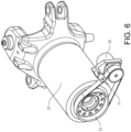
- Figure 6 shows selected parts of the connection arrangement according to figures 4 and 5 , including the rotation damper device 10, the driving belt 11, the part 12 (that forms a rear end portion of the first connection element 21) and the second connection element 31 that is fixed to the rear vehicle section 3 and surrounds the first connection element 21.
- Figure 7 shows the connection arrangement 4 provided with a second embodiment of the rotation damper device 100.
- the damper device 100 is more integrated into the connection arrangement 4 so that no driving belt or other driving connection is needed.
- a part 100b of the damper device 100 (see also schematic figure 11 ) is fixed to the rear vehicle section 3 by means of, in this example, a locking member 105 that is capable of being unlocked so as to disengage the damper device 100 and allow free rotation between the front and rear vehicle sections 2, 3.
- the part 100b may be fixed directly to the rear vehicle section 3 without any locking member 105.
- Figure 8 shows a sectional view of the connection arrangement 4 according to figure 7 .
- the connection arrangement 4 comprises the first connection element 21 fixed to the front vehicle section 2 and the second connection element 31 fixed to the rear vehicle section 3, wherein the first connection element 21 is arranged to be rotatable inside the second connection element 31 by means of roller bearings 25.
- the part 12 that forms a rear end portion of the first connection element 21 is in this case directly connected and fixed to a part 100a of the damper device 100, wherein the first and second parts 100a and 100b are allowed to rotate in relation to each other (see figure 11 ).
- the locking member 105 is not shown in figure 8 and, in line with figure 5 , neither is the rear portion 8b of the drive shaft shown in figure 8 .
- Figure 9 shows selected parts of the connection arrangement 4 according to figures 7 and 8 , including the rotation damper device 100, the second part 100b of the damper device 100 (where the second part 100b is connected to the rear end portion of the first connection element 21), the locking member 105 (that locks the second part 100b to the rear vehicle section 3) and the second connection element 31 that is fixed to the rear vehicle section 3 and surrounds the first connection element 21.
- Figure 9 also indicates that the locking member 105 is provided with clamping elements 106 arranged to fix a flange of the second part 100b of the rotation damper device 100 located between the clamping elements 106. Accordingly, when the clamping elements 106 are engaged and hold the flange of the second part 100b of the rotation damper device 100 in a steady grip, the second part 100b is prevented from rotating in relation to the rear vehicle section 3 (since locking member 105 is fixed to the rear vehicle section 3), from which it follows that the first and second parts 100a, 100b of the damper device 100 will rotate in relation to each other when the front and rear vehicle sections 2, 3 rotate in relation to each other.
- FIGS 10 and 11 show, in schematic sectional views, the first and second embodiment of the rotation damper devices 10, 100, respectively. It should be noted that these figures show simplified versions of the two damper devices just to show their principal structure and function.
- each of the damper devices 10, 100 comprises a first part 10a and, concentrically outside of the first part, a second part 10b, 100b.
- Bearings 30 are arranged circumferentially between the first and second parts 10a, 10b, 100a, 100b that allow the first and second parts to rotate in relation to each other about a rotation axis that, with reference to the page that shows figures 10-11 , extends horizontally and in the same plane as the page (and that is substantially parallel with the longitudinal direction of the vehicle 1).
- a viscous liquid 10c, 100c in the form of silicon fluid is arranged in the annular space formed between the first and second parts 10a, 10b, 100a, 100b and the bearings 30, which also function as seals to prevent leakage of the viscous liquid 10c, 100c in the axial direction of the rotation damper device 10, 100.
- the viscous liquid 10c, 100c has the effect that a relative rotation between the first and second parts 10a, 10b, 100a, 100b is transferred in a dampened manner. For instance, if the inner part 10a, 100a starts rotating while the outer part 10b, 100b is stationary, the rotational movement will be transferred to the outer part but not directly as in a fixed connection but with some delay and with a decreased rate of change (acceleration) of the rotation transferred to the outer part. Also, the acceleration of the rotation of the inner part will be decreased compared to free rotation since force and energy will be at least temporarily absorbed by the viscous liquid.
- the first (inner) part 10a is connected, via protruding part 10e, to the front vehicle section 2 via drive belt 11 and first connection element 21 as described above.
- the second (outer) part 10b forms an outer body that is fixed to the rear vehicle section 2. Accordingly, if the front vehicle section 2 rotates in relation to the rear vehicle section 3, the first and second parts 10a, 10b will rotate in relation to each other and the relative rotation will be transferred in a dampened manner.
- the first (inner) part 100a is connected to the front vehicle section 2 directly via first connection element 21 as described above.
- the second (outer) part 100b forms an outer body that is fixed to the rear vehicle section 2 (via locking member 105 that clamps flange 101 in the example above). Accordingly, if the front vehicle section 2 rotates in relation to the rear vehicle section 3, the first and second parts 100a, 100b will rotate in relation to each other and the relative rotation will be transferred in a dampened manner.
- the rotation damper device 100 is arranged concentrically around the longitudinal axis 5 about which the connection arrangement 4 allows the front and rear sections 2, 3 to rotate in relation to each other.
Landscapes
- Engineering & Computer Science (AREA)
- Mechanical Engineering (AREA)
- Chemical & Material Sciences (AREA)
- Combustion & Propulsion (AREA)
- Transportation (AREA)
- General Engineering & Computer Science (AREA)
- Acoustics & Sound (AREA)
- Aviation & Aerospace Engineering (AREA)
- Physics & Mathematics (AREA)
- Architecture (AREA)
- Structural Engineering (AREA)
- Vehicle Body Suspensions (AREA)
- Fluid-Damping Devices (AREA)
- Harvester Elements (AREA)
- Working Measures On Existing Buildindgs (AREA)
Description
- The invention relates to an articulated working machine vehicle, such as an articulated hauler, comprising a vehicle front section and a vehicle rear section pivotally connected via a connection arrangement configured to control a pivot angle between the front and rear sections for steering of the vehicle, the connection arrangement further being configured to allow the front and rear sections to rotate in relation to each other about a longitudinal axis of the vehicle.
- Although the invention will be described with respect to an articulated hauler it is not restricted to this particular vehicle but may also be used in other articulated vehicles.
- Articulated working machine vehicles of the above type are often used on bumpy roads causing the vehicle front section (pull unit, tractor, etc.) and the vehicle rear section (load unit, trailer, etc.) to rotate significantly in relation to each other about a rotational axis extending longitudinally along the vehicle through the connection arrangement that connects the front and rear sections. Such rotation creates strong forces onto an operator/driver of the vehicle, who normally is located in a cab on the front section at a significant distance above the rotational axis/the connection arrangement and thus will be forced from side to side while driving on such roads.
-
WO2015/094025A1 discloses an articulated working machine vehicle where the connection arrangement that connects the front and rear vehicle portions is provided with an active torque generator adapted to selectively impart a torque about the geometrical axis of rotation between the front and rear vehicle portions. The active torque generator comprises e.g. an electric motor and appears to be directed to provide a torque onto a shaft of the first or second vehicle portions for reducing a difference in wheel normal force between left and right sides of the vehicle when positioned sideways on a slope.
Moreover, documentUS 3 035 654 A discloses an articulated working machine according to the preamble of independent claim 1. - A purpose of the present invention is to increase the comfort of the operator while driving an articulated working machine vehicle on bumpy roads.
- The invention relates to an articulated working machine vehicle, such as an articulated hauler, comprising a front section and a rear section pivotally connected via a connection arrangement configured to control a pivot angle between the front and rear sections for steering of the vehicle, the connection arrangement further being configured to allow the front and rear sections to rotate in relation to each other about a longitudinal axis of the vehicle. Further, the connection arrangement comprises a rotation damper device arranged to transfer dampened relative rotation about the longitudinal axis between the front section and the rear section of the vehicle.
- Conventionally, the front and rear vehicle sections can in principal rotate freely in relation to each other, i.e. the relative rotation is not transferred at all. This means that a driver of the vehicle is exposed to sudden change of rotational speed, especially if a wheel on one side of the front section (i.e. the section provided with the driver's cab) loses support or if the rotation change direction, such as if the front section tilts towards one side to the limit and then rotates back. Further, with free rotation either vehicle section can gain rotational speed (and consequently kinetic energy) which can lead to roll over.
- If the connection arrangement would be rotationally locked so that relative rotation between the front and rear vehicle sections would be prevented, any rotation would be transferred between the two sections. This would lead to a stiff vehicle not very well adapted to bumpy roads. The articulated vehicle according to this disclosure may be regarded as something in-between free rotation and locked rotation (where relative rotation is prevented); the rotation is indeed transferred between the two vehicle sections as with locked rotation but it is transferred in a dampened manner so that relative rotation is allowed, which it is not with locked rotation, and so that the relative rotation, or at least the rate of change of the relative rotation, becomes reduced compared to free rotation.
- An advantage of an articulated working machine of the inventive type is thus that the relative rotation is dampened, or rather the rate of change, i.e. the acceleration, of the relative rotation is dampened. This improves driver comfort, and it also increases safety (reduces risk of roll over) as also the rotation speed and energy is lowered.
- A particular example where a dampened relative rotation is advantageous is when there is a deep hole on one side of the road. When a wheel of either the front or rear vehicle section reaches the hole the wheel will rapidly move downwards into the hole (and the suspension/shock absorber of that wheel will collapse to a certain degree). However, because of the rotation damper device the vehicle section in question will not rotate and tilt as rapidly as the wheel goes down into the whole. Besides improving driver's comfort, in the case where the front vehicle section reaches the hole, this could prevent roll over for the vehicle section concerned if the hole is deep enough to be critical for roll over. Compared to
WO2015/094025A1 the above vehicle design differs in that rotation damping is provided, no active torque is generated. The effects and advantages described above are thus not achieved by the vehicle ofWO2015/094025A1 . Further, the rotation damping device is preferably a passive system that can be made more simple, cost-effective and reliable compared to the active system ofWO2015/094025A1 . - According to the invention, the rotation damper device comprises a first part fixed to the vehicle front section and a second part fixed to the vehicle rear section so that the first part rotates in relation to the second part when the front and rear vehicle sections rotate in relation to each other about the longitudinal axis of the vehicle, wherein the rotation damper device further comprises a viscous liquid arranged between and in connection with the first and a second part so as to provide for a dampened transfer of rotation between the first and second parts.
- The first and second parts of the rotation damper device are thus connected via a viscous fluid that dampens the transfer of a rotational movement between the two parts. For instance, if the first part suddenly starts to rotate while the second part is stationary, the viscous liquid will slow down the rate of change of the rotation of the first part while at the same time start rotating the second part but at a lower rate of change than the first part. The viscous fluid may be based on silicon. The damping moment depends on the viscosity of the fluid and the distance/gap between the first and second parts of the rotation damper. Different viscosities and/or gaps may thus be used to adapt the rotation damper device to a particular application.
- In an embodiment the first and second parts of the rotation damper device are arranged concentrically and wherein the viscous liquid is arranged radially in between the first and second parts. This provides for an efficient damper device both with regard to function and space required.
- In an embodiment at least one of the first and second parts of the rotation damper device is connected to its corresponding vehicle section via a driving connection, such as a driving belt. Thus, the first or second part of the rotation damper device may be indirectly connected via the driving connection to its corresponding vehicle section. The damper device may thereby be arranged at a side of the connection arrangement, which may be suitable if there is no room in/at the connection arrangement or if it is inconvenient or difficult to modify the connection arrangement so as to integrate a damper device.
- In an embodiment the connection arrangement comprises a first connection element fixed to the front vehicle section and a second connection element fixed to the rear vehicle section, wherein the first connection element is arranged to be rotatable inside the second connection element and wherein the rotation damper device is arranged in association with a rear end portion of the first connection element. This is a suitable position for the rotation damper device in many articulated working machine vehicles. Preferably, the first part of the rotation damper device is connected to the first connection element.
- In an embodiment the longitudinal axis, about which the connection arrangement allows the front and rear sections to rotate in relation to each other, extends through the connection arrangement.
- In an embodiment the rotation damper device is arranged concentrically around the longitudinal axis about which the connection arrangement allows the front and rear sections to rotate in relation to each other. A rotation damper device integrated into the connection arrangement may be arranged in this way.
- In an embodiment the rotation damper device comprises a locking member arranged to lock the second part of the rotation damper device to the rear vehicle section. Such a locking member is useful when it for some reason is an advantage to not fix or lock the second part directly to the rear vehicle section. One reason may be that it is difficult to lock the second part directly. Another reason may be that it is desired to have the possibility to deactivate the rotation damping device so as to allow free relative rotation between the front and rear vehicle sections. In such a case the locking member is preferably adapted to be easy to unlock so that the second part can rotate freely in relation to the rear vehicle section.
- In an embodiment the locking member is fixed to the rear vehicle section, wherein the locking member is provided with clamping elements arranged to fix a flange of the second part of the rotation damper device located between the clamping elements. This provides for a locking member that can be unlocked (by releasing the clamping elements) so as to allow free rotation of the second part of the rotation damper device.
- In an embodiment the vehicle front section is provided with an operator/driver cab. Although the advantages related to operator comfort would not be relevant, the use of the rotation damper device is useful also for an autonomous vehicle (to avoid roll over) that not necessarily need be provided with an operator cab.
- In an embodiment the vehicle rear section is provided with a load container.
- In an embodiment each of the vehicle front and rear sections is provided with at least one pair of wheels.
- Further advantages and advantageous features of the invention are disclosed in the following description and in the dependent claims.
- With reference to the appended drawings, below follows a more detailed description of embodiments of the invention cited as examples.
- In the drawings:
-
Fig. 1 shows an articulated hauler provided with a rotation damper device according to this disclosure, -
Fig. 2 shows a magnification of a connection arrangement of the articulated hauler offigure 1 , -
Fig. 3 shows a view from below of the connection arrangement according tofigure 2 , -
Fig. 4 shows the connection arrangement according tofigures 2 and3 provided with a first embodiment of the rotation damper device, -
Fig. 5 shows a sectional view of the connection arrangement according tofigure 4 , -
Fig. 6 shows parts of the connection arrangement according tofigure 4 , -
Fig. 7 shows the connection arrangement according tofigures 2 and3 provided with a second embodiment of the rotation damper device, -
Fig. 8 shows a sectional view of the connection arrangement according tofigure 7 , -
Fig. 9 shows parts of the connection arrangement according tofigure 7 , -
Fig. 10 shows, in a schematic sectional view, the first embodiment of the rotation damper device, and -
Fig. 11 shows, in a schematic sectional view, the second embodiment of the rotation damper device. - Example embodiments of the invention will now be described with reference to
figures 1-11 . -
Figure 1 shows an articulated working machine vehicle in the form of an articulated hauler 1 comprising afront section 2 and arear section 3 pivotally connected via aconnection arrangement 4 configured to control a pivot angle between the front andrear sections connection arrangement 4 is further configured to allow the front andrear sections longitudinal axis 5 of the vehicle 1. As will be further described below, theconnection arrangement 4 is provided with arotation damper device front section 2 and therear section 3 of the vehicle 1. - As further shown in
figure 1 , thefront section 2 is provided with an operator/driver cab 6 and the vehiclerear section 3 is provided with aload container 7. Further, each of the vehicle front andrear sections wheels -
Figure 2 shows a magnification of theconnection arrangement 4 of the articulated hauler 1 offigure 1 , andfigure 3 shows a view from below of theconnection arrangement 4. As shown infigure 3 , a drive shaft withfront portion 8a andrear portion 8b for driving of therear section wheels 9b extends along the vehicle from the front vehicle section 2 (which is provided with a power source, transmission etc., not shown) through theconnection arrangement 4 and further along therear vehicle section 3. Front and reardrive shaft portions connection arrangement 4 so as to allow a varying pivot angle as well as relative rotation between the front andrear vehicle sections -
Figure 4 shows theconnection arrangement 4 provided with a first embodiment of therotation damper device 10. Thedamper device 10 is fixed to a wall section of therear vehicle section 3. A drivingbelt 11 connects arotatable part 10a of the damper device 10 (see schematicfigure 10 ) with apart 12 that is fixed to thefront vehicle section 2, whichpart 12 forms thus rotates with thefront vehicle section 2. Accordingly, when thefront section 2 rotates in relation to therear section 3 thepart 12 rotates therotatable part 10a of thedamper device 10 via thedrive belt 11. -
Figure 5 shows a sectional view of theconnection arrangement 4 shown infigure 4 . As can be seen infigure 5 , theconnection arrangement 4 comprises afirst connection element 21 that is fixed to thefront vehicle section 2 and asecond connection element 31 that is fixed to therear vehicle section 3. Thefirst connection element 21 is arranged to be rotatable inside thesecond connection element 31 by means of a set ofroller bearings 25. Thepart 12 that is connected to therotation damper device 10 viabelt 11 forms a rear end portion of thefirst connection element 21. Therear portion 8b of the drive shaft is not shown infigure 5 . -
Figure 6 shows selected parts of the connection arrangement according tofigures 4 and5 , including therotation damper device 10, the drivingbelt 11, the part 12 (that forms a rear end portion of the first connection element 21) and thesecond connection element 31 that is fixed to therear vehicle section 3 and surrounds thefirst connection element 21. -
Figure 7 shows theconnection arrangement 4 provided with a second embodiment of therotation damper device 100. In this case thedamper device 100 is more integrated into theconnection arrangement 4 so that no driving belt or other driving connection is needed. Apart 100b of the damper device 100 (see also schematicfigure 11 ) is fixed to therear vehicle section 3 by means of, in this example, a lockingmember 105 that is capable of being unlocked so as to disengage thedamper device 100 and allow free rotation between the front andrear vehicle sections part 100b may be fixed directly to therear vehicle section 3 without any lockingmember 105. -
Figure 8 shows a sectional view of theconnection arrangement 4 according tofigure 7 . Also in this case (seefigure 5 ), theconnection arrangement 4 comprises thefirst connection element 21 fixed to thefront vehicle section 2 and thesecond connection element 31 fixed to therear vehicle section 3, wherein thefirst connection element 21 is arranged to be rotatable inside thesecond connection element 31 by means ofroller bearings 25. However, thepart 12 that forms a rear end portion of thefirst connection element 21 is in this case directly connected and fixed to apart 100a of thedamper device 100, wherein the first andsecond parts figure 11 ). The lockingmember 105 is not shown infigure 8 and, in line withfigure 5 , neither is therear portion 8b of the drive shaft shown infigure 8 . -
Figure 9 shows selected parts of theconnection arrangement 4 according tofigures 7 and8 , including therotation damper device 100, thesecond part 100b of the damper device 100 (where thesecond part 100b is connected to the rear end portion of the first connection element 21), the locking member 105 (that locks thesecond part 100b to the rear vehicle section 3) and thesecond connection element 31 that is fixed to therear vehicle section 3 and surrounds thefirst connection element 21. -
Figure 9 also indicates that the lockingmember 105 is provided with clampingelements 106 arranged to fix a flange of thesecond part 100b of therotation damper device 100 located between the clampingelements 106. Accordingly, when the clampingelements 106 are engaged and hold the flange of thesecond part 100b of therotation damper device 100 in a steady grip, thesecond part 100b is prevented from rotating in relation to the rear vehicle section 3 (since lockingmember 105 is fixed to the rear vehicle section 3), from which it follows that the first andsecond parts damper device 100 will rotate in relation to each other when the front andrear vehicle sections -
Figures 10 and 11 show, in schematic sectional views, the first and second embodiment of therotation damper devices figures 10 and 11 , each of thedamper devices first part 10a and, concentrically outside of the first part, asecond part Bearings 30 are arranged circumferentially between the first andsecond parts figures 10-11 , extends horizontally and in the same plane as the page (and that is substantially parallel with the longitudinal direction of the vehicle 1). Aviscous liquid second parts bearings 30, which also function as seals to prevent leakage of theviscous liquid rotation damper device - The
viscous liquid second parts inner part outer part - In the case of the
rotation damper device 10 shown infigure 10 , the first (inner)part 10a is connected, via protrudingpart 10e, to thefront vehicle section 2 viadrive belt 11 andfirst connection element 21 as described above. The second (outer)part 10b forms an outer body that is fixed to therear vehicle section 2. Accordingly, if thefront vehicle section 2 rotates in relation to therear vehicle section 3, the first andsecond parts - In the case of the
rotation damper device 100 shown infigure 11 , the first (inner)part 100a is connected to thefront vehicle section 2 directly viafirst connection element 21 as described above. The second (outer)part 100b forms an outer body that is fixed to the rear vehicle section 2 (via lockingmember 105 that clampsflange 101 in the example above). Accordingly, if thefront vehicle section 2 rotates in relation to therear vehicle section 3, the first andsecond parts - In the case of the
rotation damper device 100 shown infigure 11 , therotation damper device 100 is arranged concentrically around thelongitudinal axis 5 about which theconnection arrangement 4 allows the front andrear sections - It is to be understood that the present invention is not limited to the embodiments described above and illustrated in the drawings; rather, the skilled person will recognize that many changes and modifications may be made, as long as they fall under the scope of the appended claims.
Claims (12)
- An articulated working machine vehicle (1), such as an articulated hauler, comprising a front section (2) and a rear section (3) pivotally connected via a connection arrangement (4) configured to control a pivot angle between the front and rear sections (2, 3) for steering of the vehicle (1), the connection arrangement (4) further being configured to allow the front and rear sections (2, 3) to rotate in relation to each other about a longitudinal axis (5) of the vehicle (1),
wherein the connection arrangement (4) comprises a rotation damper device (10, 100) arranged to transfer dampened relative rotation about the longitudinal axis (5) between the front section (2) and the rear section (3) of the vehicle (1), the articulated vehicle being characterised in that the rotation damper device (10, 100) comprises a first part (10a, 100a) fixed to the vehicle front section (2) and a second part (10b, 100b) fixed to the vehicle rear section (3) so that the first part rotates in relation to the second part when the front and rear vehicle sections rotate in relation to each other about the longitudinal axis of the vehicle, and wherein the rotation damper device (10, 100) further comprises a viscous liquid (10c, 100c) arranged between and in connection with the first and a second part (10a, 10b, 100a, 100b) so as to provide for a dampened transfer of rotation between the first and second parts. - The articulated vehicle (1) according to claim 1, wherein the first and second parts (10a, 10b, 100a, 100b) of the rotation damper device (10, 100) are arranged concentrically and wherein the viscous liquid (10c, 100c) is arranged radially in between the first and second parts (10a, 10b, 100a, 100b).
- The articulated vehicle (1) according to claim 1 or 2, wherein at least one of the first and second parts (10a, 10b, 100a, 100b) of the rotation damper device (10, 100) is connected to its corresponding vehicle section (2, 3) via a driving connection (11).
- The articulated vehicle (1) according to any of the above claims, wherein the connection arrangement (4) comprises a first connection element (21) fixed to the front vehicle section (2) and a second connection element (31) fixed to the rear vehicle section (3), wherein the first connection element (21) is arranged to be rotatable inside the second connection element (31) and wherein the rotation damper device (10, 100) is arranged in association with a rear end portion (12) of the first connection element (21).
- The articulated vehicle (1) according to claim 4, wherein the first part (10a, 100a) of the rotation damper device (10, 100) is connected to the first connection element (21).
- The articulated vehicle (1) according to any of the above claims, wherein the longitudinal axis (5), about which the connection arrangement (4) allows the front and rear sections (2, 3) to rotate in relation to each other, extends through the connection arrangement (4).
- The articulated vehicle (1) according to any of the above claims, wherein the rotation damper device (10, 100) is arranged concentrically around the longitudinal axis (5) about which the connection arrangement allows the front and rear sections (2, 3) to rotate in relation to each other.
- The articulated vehicle (1) according to any of the above claims, wherein the rotation damper device (10, 100) comprises a locking member (105) arranged to lock the second part (10b, 100b) of the rotation damper device to the rear vehicle section (3).
- The articulated vehicle (1) according to claim 8, wherein the locking member (105) is fixed to the rear vehicle section (2) and wherein the locking member (105) is provided with clamping elements (106) arranged to fix a flange of the second part (100b) of the rotation damper device located between the clamping elements (106).
- The articulated vehicle (1) according to any of the above claims, wherein the vehicle front section (2) is provided with an operator/driver cab (6).
- The articulated vehicle (1) according to any of the above claims, wherein the vehicle rear section (3) is provided with a load container (7).
- The articulated vehicle (1) according to any of the above claims, wherein each of the vehicle front and rear sections (2, 3) is provided with at least one pair of wheels (9a, 9b).
Applications Claiming Priority (1)
| Application Number | Priority Date | Filing Date | Title |
|---|---|---|---|
| PCT/EP2020/052236 WO2021151488A1 (en) | 2020-01-30 | 2020-01-30 | An articulated working machine vehicle |
Publications (3)
| Publication Number | Publication Date |
|---|---|
| EP4096989A1 EP4096989A1 (en) | 2022-12-07 |
| EP4096989B1 true EP4096989B1 (en) | 2024-01-10 |
| EP4096989C0 EP4096989C0 (en) | 2024-01-10 |
Family
ID=69526204
Family Applications (1)
| Application Number | Title | Priority Date | Filing Date |
|---|---|---|---|
| EP20704202.9A Active EP4096989B1 (en) | 2020-01-30 | 2020-01-30 | An articulated working machine vehicle |
Country Status (5)
| Country | Link |
|---|---|
| US (1) | US12420865B2 (en) |
| EP (1) | EP4096989B1 (en) |
| KR (1) | KR20220129080A (en) |
| CN (1) | CN115210130A (en) |
| WO (1) | WO2021151488A1 (en) |
Family Cites Families (19)
| Publication number | Priority date | Publication date | Assignee | Title |
|---|---|---|---|---|
| GB368744A (en) * | 1929-12-12 | 1932-03-09 | Carlo Cohen Venezian | Improvements in or relating to road vehicles |
| US3035654A (en) | 1958-02-21 | 1962-05-22 | Wilson Nuttall Raimond Enginee | Articulated tracked vehicles |
| DE2658932B2 (en) * | 1976-12-24 | 1980-05-22 | O & K Orenstein & Koppel Ag, 1000 Berlin | Central joint for a self-driving, steered vehicle |
| US4353572A (en) | 1980-06-02 | 1982-10-12 | The United States Of America As Represented By The Secretary Of The Army | Articulation joint roll stabilizer |
| DE3817031C2 (en) * | 1988-05-19 | 1994-02-24 | Danfoss As | Steering damper for a kink-controlled vehicle with hydraulic steering |
| FR2663590A1 (en) * | 1990-06-21 | 1991-12-27 | Mecalac | Civil engineering works vehicle or the like including an articulated two-part chassis |
| US5400878A (en) | 1993-03-12 | 1995-03-28 | United Technologies Corporation | Rotary viscous damper |
| DE10029691C2 (en) | 2000-06-16 | 2002-04-25 | Hako Gmbh | Articulated floor cleaning vehicle |
| EP1975045B1 (en) * | 2007-03-27 | 2010-12-01 | Aebi & Co. AG | All-terrain vehicle with skew suppression |
| EP2218835B1 (en) | 2009-02-12 | 2012-10-31 | Luc Didden | Shovel loader comprising two hinged frames. |
| SE533604C2 (en) * | 2009-03-18 | 2010-11-02 | Scania Cv Abp | Damping system for articulated vehicles and method for controlling the damping power of such damping system |
| WO2012154087A1 (en) * | 2011-05-06 | 2012-11-15 | Volvo Construction Equipment Ab | A method for controlling a working machine, and a working machine |
| WO2013158718A1 (en) | 2012-04-18 | 2013-10-24 | Getman Corporation | Joint of an articulated vehicle |
| DE102012209690B4 (en) * | 2012-06-11 | 2020-06-18 | Saf-Holland Gmbh | Steering arrangement |
| DE102014205990B4 (en) * | 2013-04-16 | 2023-10-26 | Ford Global Technologies, Llc | Articulated connection for transmitting a steering movement to a wheel of a vehicle and steering lever |
| GB2536841A (en) * | 2013-12-20 | 2016-09-28 | Volvo Constr Equip Ab | Control assembly for a vehicle |
| FR3057232B1 (en) * | 2016-10-11 | 2019-06-21 | Jtekt Europe | STEERING LINK WITH ELASTIC SHOCK ABSORBER PROTECTED UNDER DIRECTION BOX BELLOW |
| EP3312476B1 (en) * | 2016-10-24 | 2021-09-29 | Volvo Car Corporation | Vehicle with transmission having a spline connection |
| US10246087B2 (en) * | 2016-12-15 | 2019-04-02 | Caterpillar Inc. | System and method for collision mitigation during machine articulation |
-
2020
- 2020-01-30 CN CN202080094375.2A patent/CN115210130A/en active Pending
- 2020-01-30 WO PCT/EP2020/052236 patent/WO2021151488A1/en not_active Ceased
- 2020-01-30 EP EP20704202.9A patent/EP4096989B1/en active Active
- 2020-01-30 US US17/759,580 patent/US12420865B2/en active Active
- 2020-01-30 KR KR1020227029739A patent/KR20220129080A/en not_active Ceased
Also Published As
| Publication number | Publication date |
|---|---|
| WO2021151488A1 (en) | 2021-08-05 |
| CN115210130A (en) | 2022-10-18 |
| US20230060686A1 (en) | 2023-03-02 |
| KR20220129080A (en) | 2022-09-22 |
| EP4096989A1 (en) | 2022-12-07 |
| US12420865B2 (en) | 2025-09-23 |
| EP4096989C0 (en) | 2024-01-10 |
Similar Documents
| Publication | Publication Date | Title |
|---|---|---|
| EP1144212B1 (en) | Wheel suspension arrangement in a vehicle | |
| DE112005001204B4 (en) | wheel support | |
| US7159695B2 (en) | Dampening for a dolly wheel within a steering system | |
| JP3988200B2 (en) | Shock absorbing steering device | |
| KR20180042588A (en) | Electric type damper for vehicle | |
| EP3967575B1 (en) | Steering device of independent drive wheel and independent drive module including same | |
| EP2475570A1 (en) | Tilt control for tilting vehicles | |
| WO2012060744A1 (en) | Telescopic vehicle steering column | |
| US12420865B2 (en) | Articulated working machine vehicle | |
| US12097741B2 (en) | Stabilizer assembly for a two-track vehicle | |
| GB2344402A (en) | Actuator | |
| WO2015097695A1 (en) | Differential assembly and method | |
| US7163079B2 (en) | Adjustable steering lock | |
| US20140285043A1 (en) | Rotational damper | |
| EP1401699B1 (en) | Articulated vehicle | |
| KR101491359B1 (en) | Electronic stability program for vehicle | |
| KR101630123B1 (en) | Steering Apparatus for Vehicle | |
| KR20190011381A (en) | Suspension device having torsion beam | |
| KR101421339B1 (en) | Steering Apparatus for Vehicle | |
| DE102019207055B4 (en) | Roll stabilizer arrangement for a vehicle | |
| EP1052158A2 (en) | Automotive hydraulic steering system | |
| EP1539505A2 (en) | Dampening for a dolly wheel within a steering system | |
| US20240017609A1 (en) | Vehicle behavior control device | |
| JP4020028B2 (en) | Electric power steering device | |
| KR100356841B1 (en) | steering linkage structure for automobile |
Legal Events
| Date | Code | Title | Description |
|---|---|---|---|
| STAA | Information on the status of an ep patent application or granted ep patent |
Free format text: STATUS: UNKNOWN |
|
| STAA | Information on the status of an ep patent application or granted ep patent |
Free format text: STATUS: THE INTERNATIONAL PUBLICATION HAS BEEN MADE |
|
| PUAI | Public reference made under article 153(3) epc to a published international application that has entered the european phase |
Free format text: ORIGINAL CODE: 0009012 |
|
| STAA | Information on the status of an ep patent application or granted ep patent |
Free format text: STATUS: REQUEST FOR EXAMINATION WAS MADE |
|
| 17P | Request for examination filed |
Effective date: 20220817 |
|
| AK | Designated contracting states |
Kind code of ref document: A1 Designated state(s): AL AT BE BG CH CY CZ DE DK EE ES FI FR GB GR HR HU IE IS IT LI LT LU LV MC MK MT NL NO PL PT RO RS SE SI SK SM TR |
|
| DAV | Request for validation of the european patent (deleted) | ||
| DAX | Request for extension of the european patent (deleted) | ||
| GRAP | Despatch of communication of intention to grant a patent |
Free format text: ORIGINAL CODE: EPIDOSNIGR1 |
|
| STAA | Information on the status of an ep patent application or granted ep patent |
Free format text: STATUS: GRANT OF PATENT IS INTENDED |
|
| RIC1 | Information provided on ipc code assigned before grant |
Ipc: F16F 15/16 20060101ALI20230807BHEP Ipc: F16F 15/023 20060101ALI20230807BHEP Ipc: F16F 9/12 20060101ALI20230807BHEP Ipc: B62D 53/00 20060101ALI20230807BHEP Ipc: B62D 21/18 20060101ALI20230807BHEP Ipc: B62D 12/00 20060101AFI20230807BHEP |
|
| INTG | Intention to grant announced |
Effective date: 20230824 |
|
| GRAS | Grant fee paid |
Free format text: ORIGINAL CODE: EPIDOSNIGR3 |
|
| GRAA | (expected) grant |
Free format text: ORIGINAL CODE: 0009210 |
|
| STAA | Information on the status of an ep patent application or granted ep patent |
Free format text: STATUS: THE PATENT HAS BEEN GRANTED |
|
| AK | Designated contracting states |
Kind code of ref document: B1 Designated state(s): AL AT BE BG CH CY CZ DE DK EE ES FI FR GB GR HR HU IE IS IT LI LT LU LV MC MK MT NL NO PL PT RO RS SE SI SK SM TR |
|
| REG | Reference to a national code |
Ref country code: GB Ref legal event code: FG4D |
|
| REG | Reference to a national code |
Ref country code: CH Ref legal event code: EP |
|
| REG | Reference to a national code |
Ref country code: DE Ref legal event code: R096 Ref document number: 602020024165 Country of ref document: DE |
|
| REG | Reference to a national code |
Ref country code: IE Ref legal event code: FG4D |
|
| U01 | Request for unitary effect filed |
Effective date: 20240206 |
|
| U07 | Unitary effect registered |
Designated state(s): AT BE BG DE DK EE FI FR IT LT LU LV MT NL PT SE SI Effective date: 20240214 |
|
| U20 | Renewal fee for the european patent with unitary effect paid |
Year of fee payment: 5 Effective date: 20240223 |
|
| PG25 | Lapsed in a contracting state [announced via postgrant information from national office to epo] |
Ref country code: IS Free format text: LAPSE BECAUSE OF FAILURE TO SUBMIT A TRANSLATION OF THE DESCRIPTION OR TO PAY THE FEE WITHIN THE PRESCRIBED TIME-LIMIT Effective date: 20240510 |
|
| PG25 | Lapsed in a contracting state [announced via postgrant information from national office to epo] |
Ref country code: GR Free format text: LAPSE BECAUSE OF FAILURE TO SUBMIT A TRANSLATION OF THE DESCRIPTION OR TO PAY THE FEE WITHIN THE PRESCRIBED TIME-LIMIT Effective date: 20240411 |
|
| PG25 | Lapsed in a contracting state [announced via postgrant information from national office to epo] |
Ref country code: HR Free format text: LAPSE BECAUSE OF FAILURE TO SUBMIT A TRANSLATION OF THE DESCRIPTION OR TO PAY THE FEE WITHIN THE PRESCRIBED TIME-LIMIT Effective date: 20240110 Ref country code: RS Free format text: LAPSE BECAUSE OF FAILURE TO SUBMIT A TRANSLATION OF THE DESCRIPTION OR TO PAY THE FEE WITHIN THE PRESCRIBED TIME-LIMIT Effective date: 20240410 |
|
| PG25 | Lapsed in a contracting state [announced via postgrant information from national office to epo] |
Ref country code: ES Free format text: LAPSE BECAUSE OF FAILURE TO SUBMIT A TRANSLATION OF THE DESCRIPTION OR TO PAY THE FEE WITHIN THE PRESCRIBED TIME-LIMIT Effective date: 20240110 |
|
| PG25 | Lapsed in a contracting state [announced via postgrant information from national office to epo] |
Ref country code: RS Free format text: LAPSE BECAUSE OF FAILURE TO SUBMIT A TRANSLATION OF THE DESCRIPTION OR TO PAY THE FEE WITHIN THE PRESCRIBED TIME-LIMIT Effective date: 20240410 Ref country code: NO Free format text: LAPSE BECAUSE OF FAILURE TO SUBMIT A TRANSLATION OF THE DESCRIPTION OR TO PAY THE FEE WITHIN THE PRESCRIBED TIME-LIMIT Effective date: 20240410 Ref country code: IS Free format text: LAPSE BECAUSE OF FAILURE TO SUBMIT A TRANSLATION OF THE DESCRIPTION OR TO PAY THE FEE WITHIN THE PRESCRIBED TIME-LIMIT Effective date: 20240510 Ref country code: HR Free format text: LAPSE BECAUSE OF FAILURE TO SUBMIT A TRANSLATION OF THE DESCRIPTION OR TO PAY THE FEE WITHIN THE PRESCRIBED TIME-LIMIT Effective date: 20240110 Ref country code: GR Free format text: LAPSE BECAUSE OF FAILURE TO SUBMIT A TRANSLATION OF THE DESCRIPTION OR TO PAY THE FEE WITHIN THE PRESCRIBED TIME-LIMIT Effective date: 20240411 Ref country code: ES Free format text: LAPSE BECAUSE OF FAILURE TO SUBMIT A TRANSLATION OF THE DESCRIPTION OR TO PAY THE FEE WITHIN THE PRESCRIBED TIME-LIMIT Effective date: 20240110 |
|
| PG25 | Lapsed in a contracting state [announced via postgrant information from national office to epo] |
Ref country code: PL Free format text: LAPSE BECAUSE OF FAILURE TO SUBMIT A TRANSLATION OF THE DESCRIPTION OR TO PAY THE FEE WITHIN THE PRESCRIBED TIME-LIMIT Effective date: 20240110 |
|
| PG25 | Lapsed in a contracting state [announced via postgrant information from national office to epo] |
Ref country code: PL Free format text: LAPSE BECAUSE OF FAILURE TO SUBMIT A TRANSLATION OF THE DESCRIPTION OR TO PAY THE FEE WITHIN THE PRESCRIBED TIME-LIMIT Effective date: 20240110 |
|
| REG | Reference to a national code |
Ref country code: CH Ref legal event code: PL |
|
| REG | Reference to a national code |
Ref country code: DE Ref legal event code: R097 Ref document number: 602020024165 Country of ref document: DE |
|
| PG25 | Lapsed in a contracting state [announced via postgrant information from national office to epo] |
Ref country code: SM Free format text: LAPSE BECAUSE OF FAILURE TO SUBMIT A TRANSLATION OF THE DESCRIPTION OR TO PAY THE FEE WITHIN THE PRESCRIBED TIME-LIMIT Effective date: 20240110 |
|
| PG25 | Lapsed in a contracting state [announced via postgrant information from national office to epo] |
Ref country code: CH Free format text: LAPSE BECAUSE OF NON-PAYMENT OF DUE FEES Effective date: 20240131 |
|
| PG25 | Lapsed in a contracting state [announced via postgrant information from national office to epo] |
Ref country code: CZ Free format text: LAPSE BECAUSE OF FAILURE TO SUBMIT A TRANSLATION OF THE DESCRIPTION OR TO PAY THE FEE WITHIN THE PRESCRIBED TIME-LIMIT Effective date: 20240110 |
|
| PG25 | Lapsed in a contracting state [announced via postgrant information from national office to epo] |
Ref country code: SK Free format text: LAPSE BECAUSE OF FAILURE TO SUBMIT A TRANSLATION OF THE DESCRIPTION OR TO PAY THE FEE WITHIN THE PRESCRIBED TIME-LIMIT Effective date: 20240110 |
|
| PG25 | Lapsed in a contracting state [announced via postgrant information from national office to epo] |
Ref country code: SM Free format text: LAPSE BECAUSE OF FAILURE TO SUBMIT A TRANSLATION OF THE DESCRIPTION OR TO PAY THE FEE WITHIN THE PRESCRIBED TIME-LIMIT Effective date: 20240110 Ref country code: SK Free format text: LAPSE BECAUSE OF FAILURE TO SUBMIT A TRANSLATION OF THE DESCRIPTION OR TO PAY THE FEE WITHIN THE PRESCRIBED TIME-LIMIT Effective date: 20240110 Ref country code: RO Free format text: LAPSE BECAUSE OF FAILURE TO SUBMIT A TRANSLATION OF THE DESCRIPTION OR TO PAY THE FEE WITHIN THE PRESCRIBED TIME-LIMIT Effective date: 20240110 Ref country code: CZ Free format text: LAPSE BECAUSE OF FAILURE TO SUBMIT A TRANSLATION OF THE DESCRIPTION OR TO PAY THE FEE WITHIN THE PRESCRIBED TIME-LIMIT Effective date: 20240110 Ref country code: CH Free format text: LAPSE BECAUSE OF NON-PAYMENT OF DUE FEES Effective date: 20240131 |
|
| PG25 | Lapsed in a contracting state [announced via postgrant information from national office to epo] |
Ref country code: MC Free format text: LAPSE BECAUSE OF FAILURE TO SUBMIT A TRANSLATION OF THE DESCRIPTION OR TO PAY THE FEE WITHIN THE PRESCRIBED TIME-LIMIT Effective date: 20240110 |
|
| PLBE | No opposition filed within time limit |
Free format text: ORIGINAL CODE: 0009261 |
|
| STAA | Information on the status of an ep patent application or granted ep patent |
Free format text: STATUS: NO OPPOSITION FILED WITHIN TIME LIMIT |
|
| PG25 | Lapsed in a contracting state [announced via postgrant information from national office to epo] |
Ref country code: MC Free format text: LAPSE BECAUSE OF FAILURE TO SUBMIT A TRANSLATION OF THE DESCRIPTION OR TO PAY THE FEE WITHIN THE PRESCRIBED TIME-LIMIT Effective date: 20240110 |
|
| 26N | No opposition filed |
Effective date: 20241011 |
|
| GBPC | Gb: european patent ceased through non-payment of renewal fee |
Effective date: 20240410 |
|
| PG25 | Lapsed in a contracting state [announced via postgrant information from national office to epo] |
Ref country code: GB Free format text: LAPSE BECAUSE OF NON-PAYMENT OF DUE FEES Effective date: 20240410 |
|
| PG25 | Lapsed in a contracting state [announced via postgrant information from national office to epo] |
Ref country code: IE Free format text: LAPSE BECAUSE OF NON-PAYMENT OF DUE FEES Effective date: 20240130 |
|
| PG25 | Lapsed in a contracting state [announced via postgrant information from national office to epo] |
Ref country code: IE Free format text: LAPSE BECAUSE OF NON-PAYMENT OF DUE FEES Effective date: 20240130 Ref country code: GB Free format text: LAPSE BECAUSE OF NON-PAYMENT OF DUE FEES Effective date: 20240410 |
|
| U20 | Renewal fee for the european patent with unitary effect paid |
Year of fee payment: 6 Effective date: 20250127 |
|
| PG25 | Lapsed in a contracting state [announced via postgrant information from national office to epo] |
Ref country code: CY Free format text: LAPSE BECAUSE OF FAILURE TO SUBMIT A TRANSLATION OF THE DESCRIPTION OR TO PAY THE FEE WITHIN THE PRESCRIBED TIME-LIMIT; INVALID AB INITIO Effective date: 20200130 |
|
| PG25 | Lapsed in a contracting state [announced via postgrant information from national office to epo] |
Ref country code: HU Free format text: LAPSE BECAUSE OF FAILURE TO SUBMIT A TRANSLATION OF THE DESCRIPTION OR TO PAY THE FEE WITHIN THE PRESCRIBED TIME-LIMIT; INVALID AB INITIO Effective date: 20200130 |
|
| PG25 | Lapsed in a contracting state [announced via postgrant information from national office to epo] |
Ref country code: TR Free format text: LAPSE BECAUSE OF FAILURE TO SUBMIT A TRANSLATION OF THE DESCRIPTION OR TO PAY THE FEE WITHIN THE PRESCRIBED TIME-LIMIT Effective date: 20240110 |
|
| U20 | Renewal fee for the european patent with unitary effect paid |
Year of fee payment: 7 Effective date: 20260126 |