EP4096445B1 - Control unit and method for controlling a group of smoking articles - Google Patents
Control unit and method for controlling a group of smoking articles Download PDFInfo
- Publication number
- EP4096445B1 EP4096445B1 EP21708366.6A EP21708366A EP4096445B1 EP 4096445 B1 EP4096445 B1 EP 4096445B1 EP 21708366 A EP21708366 A EP 21708366A EP 4096445 B1 EP4096445 B1 EP 4096445B1
- Authority
- EP
- European Patent Office
- Prior art keywords
- smoking articles
- group
- path
- sensor
- cigarettes
- Prior art date
- Legal status (The legal status is an assumption and is not a legal conclusion. Google has not performed a legal analysis and makes no representation as to the accuracy of the status listed.)
- Active
Links
Images


Classifications
-
- A—HUMAN NECESSITIES
- A24—TOBACCO; CIGARS; CIGARETTES; SIMULATED SMOKING DEVICES; SMOKERS' REQUISITES
- A24C—MACHINES FOR MAKING CIGARS OR CIGARETTES
- A24C5/00—Making cigarettes; Making tipping materials for, or attaching filters or mouthpieces to, cigars or cigarettes
- A24C5/32—Separating, ordering, counting or examining cigarettes; Regulating the feeding of tobacco according to rod or cigarette condition
- A24C5/34—Examining cigarettes or the rod, e.g. for regulating the feeding of tobacco; Removing defective cigarettes
- A24C5/3412—Examining cigarettes or the rod, e.g. for regulating the feeding of tobacco; Removing defective cigarettes by means of light, radiation or electrostatic fields
-
- B—PERFORMING OPERATIONS; TRANSPORTING
- B65—CONVEYING; PACKING; STORING; HANDLING THIN OR FILAMENTARY MATERIAL
- B65B—MACHINES, APPARATUS OR DEVICES FOR, OR METHODS OF, PACKAGING ARTICLES OR MATERIALS; UNPACKING
- B65B19/00—Packaging rod-shaped or tubular articles susceptible to damage by abrasion or pressure, e.g. cigarettes, cigars, macaroni, spaghetti, drinking straws or welding electrodes
- B65B19/02—Packaging cigarettes
- B65B19/12—Inserting the cigarettes, or wrapped groups thereof, into preformed containers
- B65B19/20—Inserting the cigarettes, or wrapped groups thereof, into preformed containers into boxes with hinged lids
-
- B—PERFORMING OPERATIONS; TRANSPORTING
- B65—CONVEYING; PACKING; STORING; HANDLING THIN OR FILAMENTARY MATERIAL
- B65B—MACHINES, APPARATUS OR DEVICES FOR, OR METHODS OF, PACKAGING ARTICLES OR MATERIALS; UNPACKING
- B65B19/00—Packaging rod-shaped or tubular articles susceptible to damage by abrasion or pressure, e.g. cigarettes, cigars, macaroni, spaghetti, drinking straws or welding electrodes
- B65B19/28—Control devices for cigarette or cigar packaging machines
- B65B19/32—Control devices for cigarette or cigar packaging machines responsive to incorrect grouping of articles or to incorrect filling of packages
-
- B—PERFORMING OPERATIONS; TRANSPORTING
- B65—CONVEYING; PACKING; STORING; HANDLING THIN OR FILAMENTARY MATERIAL
- B65B—MACHINES, APPARATUS OR DEVICES FOR, OR METHODS OF, PACKAGING ARTICLES OR MATERIALS; UNPACKING
- B65B57/00—Automatic control, checking, warning, or safety devices
- B65B57/10—Automatic control, checking, warning, or safety devices responsive to absence, presence, abnormal feed, or misplacement of articles or materials to be packaged
-
- H—ELECTRICITY
- H01—ELECTRIC ELEMENTS
- H01F—MAGNETS; INDUCTANCES; TRANSFORMERS; SELECTION OF MATERIALS FOR THEIR MAGNETIC PROPERTIES
- H01F7/00—Magnets
-
- B—PERFORMING OPERATIONS; TRANSPORTING
- B65—CONVEYING; PACKING; STORING; HANDLING THIN OR FILAMENTARY MATERIAL
- B65B—MACHINES, APPARATUS OR DEVICES FOR, OR METHODS OF, PACKAGING ARTICLES OR MATERIALS; UNPACKING
- B65B35/00—Supplying, feeding, arranging or orientating articles to be packaged
- B65B35/30—Arranging and feeding articles in groups
- B65B35/40—Arranging and feeding articles in groups by reciprocating or oscillatory pushers
Definitions
- the present invention relates to a unit and a method for controlling a group of smoking articles, in particular, each comprising a portion containing metal material.
- a cigarette packing machine comprises a unit for forming groups of cigarettes, which receives as input a mass of cigarettes fed along a feed channel, and supplies as output a succession of orderly groups of cigarettes fed to a subsequent wrapping line.
- a unit for forming groups of cigarettes comprises a vertical hopper, which has an upper input portion connected to the feed channel feeding the mass of cigarettes, and a lower portion provided with a plurality of output mouths.
- Each output mouth comprises a number of vertical tiny channels (or vertical veins), along each of which a row of cigarettes descends by gravity, and is cyclically engaged by a respective pushing element which extracts a group of cigarettes from the bottom of the hopper and feeds the group of cigarettes to a pocket of a forming conveyor that is stationary in front of the output mouth.
- Each pushing element is shaped like a comb and has a number of teeth which transversely cross the tiny channels of the output mouth in order to push a group of cigarettes out of the tiny channels and feed the group of cigarettes to the pocket of the forming conveyor.
- an optical control station which acquires one or more images of the ends of all the cigarettes making up each group of cigarettes inserted in a pocket of the forming conveyor; the image of the ends of all the cigarettes is then processed both to verify the correct filling of the cigarette tips (that is, the ends of the cigarettes opposite the filter where the tobacco is "visible”) and to verify the correct longitudinal orientation of the cigarettes (i.e., to verify that all cigarettes have the same longitudinal orientation so that all tips are on the same side and, consequently, all filters are on the other side).
- Patent applications US2019133178A1 and US2019261677A1 describe a device for identifying physical parameters of cylindrical articles of the tobacco industry during axial transfer thereof; the device comprises a radiation emitter, which emits radiations that pass through the articles, and a sensor, which is arranged on the opposite side of the emitter, is sensitive to the radiations, and is designed to detect the attenuation experienced by the radiations after passing through the articles.
- a unit and a method are provided for controlling a group of smoking articles, each comprising a portion containing metal material, as claimed in the appended claims.
- Number 1 in Figure 1 indicates, as a whole, a rigid, hinged-lid cigarette packet comprising a group 2 of cigarettes 3 consisting of twenty cigarettes 3 arranged in three rows (of seven-six-seven cigarettes 3 each, respectively).
- each cigarette 3 comprises a length of tobacco 4 wrapped in a respective tubular paper wrapping and a filter 5 which is stably connected to the length of tobacco 4 by means of a strap.
- Metal material is contained in the filter 5 (as for example described in patent application WO2005020723A1 ).
- the metal material could also be contained in the length of tobacco 4.
- this metal material may have different shapes.
- this metal material can be granular, and therefore be dispersed in a more or less extended portion of the filter 5 or of the length of tobacco 4, or it can be a linear or reticular element of elongated, tubular or cylindrical shape, or it can be shaped as a plurality of metal elements dispersed or aligned in the filter 5 or in the length of tobacco 4.
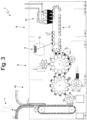
- Figure 3 shows a packing machine 7 which makes the packet 1 of cigarettes and comprises a forming unit 8 in which the groups 2 of cigarettes 3 are formed, a wrapping unit 9 in which a sheet of wrapping material is wrapped around each group 2 of cigarettes 3 to form an inner wrapping, and a wrapping unit 10 in which a blank is folded around each inner wrapping to form an outer container provided with a hinged lid, and thus complete the making of a packet 1 of cigarettes.
- the forming unit 8 comprises a forming conveyor belt 11, which supports a plurality of pockets 12, each designed to receive and move a corresponding group 2 of cigarettes 3.
- the forming conveyor 11 moves stepwise to feed each pocket 12 along an annular forming path P1.
- a feed station S is arranged along the forming path P1, in which four groups 2 of cigarettes 3 are simultaneously inserted (by moving along an insertion path P2 perpendicular to the forming path P1) into respective pockets 12 which are stationary.
- a hopper 13 is arranged in the feed station S, the former containing a mass of cigarettes 3 and having four twin output mouths 14 at the bottom, through each of which a group 2 of cigarettes 3 is extracted and inserted into a corresponding pocket 12 which is stationary in front of the output mouth 14.
- Each output mouth 14 is associated with a corresponding pushing element 15, which makes a linear reciprocating movement along the insertion path P2 to cyclically cross the output mouth 14 and axially push a group 2 of cigarettes 3 towards a corresponding pocket 12 which is stationary in front of the output mouth 14.
- the forming unit 11 comprises four tubular guide ducts 16, each of which is arranged in front of a corresponding output mouth 14 and guides the forward movement of a group 3 of cigarettes which, once it exits the output mouth 14 of the hopper 13, must reach a stationary pocket 12; that is, each guide duct 16 connects an output mouth 14 to a stationary pocket 12.
- each guide duct 16 has an internal passage channel having a substantially rectangular cross section which reproduces (with a small clearance) a cross section of the groups 2 of cigarettes 3; the passage channel of each guide duct 16 may also comprise ribs which reproduce the circular shape of the cigarettes.
- the packing machine 7 comprises a (at least one) control unit 17 which allows the correct longitudinal orientation of the individual cigarettes 3 in each group 2 of cigarettes 3 to be verified effectively and efficiently independently of the external appearance of the cigarettes 3; in other words, the control unit 17 makes it possible to verify that all cigarettes 3 in each group 2 of cigarettes 3 have the same longitudinal orientation (as shown in Figure 7 ), that is, the control unit 17 makes it possible to verify that in each group 2 of cigarettes 3 there are no cigarettes 3 oriented longitudinally in a different way than (opposite to) the other cigarettes 3 (as shown in Figure 8 ).
- twin control units 17 are provided, each of which is coupled to a corresponding guide duct 16 and is arranged along the corresponding insertion path P2.
- each control unit 17 comprises a sensor 18, which is arranged in a fixed position along the insertion path P2 followed by the groups 2 of cigarettes 3, and a processing device 19, which is coupled to the sensor 18 and is configured to establish whether, depending on the signals provided by the sensor 18, the group 2 of cigarettes 3 moving along the insertion path P2 has or has not all the cigarettes 3 with a same longitudinal orientation.
- the sensor 18 is an electromagnetic sensor and is sensitive to the presence of the metal material contained in the cigarettes 3.
- each control unit 17 the processing device 19 reads the sensor 18 when a group 2 of cigarettes 3 is moving near (in proximity to) the sensor 18, that is, when the group 2 of cigarettes 3 is moving (along the insertion path P2) with respect to the sensor 18.
- the processing device 19 reads the sensor 18 when a group 2 of cigarettes 3 is stationary near (in proximity to) the sensor 18.
- each control unit 17 the processing device 19 is configured to: detect a time development x(t) of a parameter x when the sensor 18 is in proximity to a group 2 of cigarettes 3 (which may be moving or stationary with respect to the sensor 18); compare the detected time development x(t) with a sample time development corresponding to a sample group 2 of cigarettes 3 in which all the cigarettes 3 have a same longitudinal orientation; and establish whether the group 2 of cigarettes 3 has or has not all the cigarettes 3 with a same longitudinal orientation depending on the result of the comparison.
- the detected time development x(t) is sufficiently similar to (i.e., not too different from) the sample development, then all the cigarettes 3 of the group 2 of cigarettes 3 have the same longitudinal orientation, whereas if the detected time development x(t) is sufficiently different from the sample development (i.e., not sufficiently similar to the sample development) at least one cigarette 3 of the group 2 of cigarettes 3 has a different longitudinal orientation (an incorrect orientation, i.e., opposite to the other cigarettes 3).
- the solid line shows a time development x(t) of the parameter x when the sensor 18 is close to a group 2 of cigarettes 3 in which all the cigarettes 3 of the group 2 of cigarettes 3 have the same longitudinal orientation
- the dashed line shows a time development x(t) of the parameter x when the sensor 18 is close to a group 2 of cigarettes 3 in which at least one cigarette 3 of the group 2 of cigarettes 3 has a different longitudinal orientation (an incorrect orientation, i.e., opposite to the other cigarettes 3).
- each sensor 18 comprises an electric oscillator circuit 20 having at least one quantity which is influenced by a proximity to the metal material contained in the filters 5 of the cigarettes 3, and a power supply 21 which applies a variable electrical voltage to the electric oscillator circuit 20 and is connected to the processing device 19.
- the electric oscillator circuit 20 comprises an inductor (i.e., an electrical component that generates a magnetic field when an electric current flows therethrough); at least one quantity which is influenced by a proximity to the metal material contained in the filters 5 of the cigarettes 3 is (directly or indirectly), for example, the inductance of the inductor.
- each sensor 18 the inductor consists of a single coil 22 (that is, the electric oscillator circuit 20 comprises a single coil 22), which is directly (galvanically) connected to the power supply 21 and is arranged in a fixed position along the corresponding insertion path P2.
- each coil 22 is wound around the corresponding guide duct 16, and thus around the corresponding insertion path P2, so that a group 2 of cigarettes 3 moving along the guide duct 16 and therefore along the insertion path P2 passes inside the coil 22 (that is, it longitudinally crosses the coil).
- each sensor 18 (or each coil 22) is arranged around the corresponding guide duct 16 in the vicinity of the end facing the forming conveyor 11 (and therefore opposite to the end facing the hopper 13); in this way, each sensor 18 (or the coil 22) is arranged in an area of the guide duct 16 which is travelled by the group 2 of cigarettes 3 at a slower forward speed (when the pushing element 15 reaches the end of the guide duct 16 facing the forming conveyor 11, its speed drops to zero and its direction of motion is reverted). It is understood that each sensor 18 (that is, the coil 22) can be arranged in any area of the duct 16.
- the presence and position of the metal material inside each coil 22 is "sensed" by the power supply 21, for example, as a change in the inductance (which involves a consequent change in the reactance, or impedance), a change in the quality factor or a change in the resonance frequency.
- the parameter x of which the time development x(t) is detected can be, for example, the inductance of the electric oscillator circuit 20 or the quality factor of the electric oscillator circuit 20.
- the coils 22 of the various sensors 18 could influence each other, thus distorting the readings; in order to avoid this drawback, it is possible to differentiate the working frequencies of the electric oscillator circuits 20 of the various sensors 18 (especially of the adjacent electric oscillator circuits 20); that is, the electric oscillator circuits 20 of the various sensors 18 have oscillation frequencies that are different from each other.
- the embodiment shown in Figure 6 has an extreme reading speed, is only sensitive to the presence of the metal material (that is, it is not affected in any way by the other components of the cigarettes such as tobacco, filters, paper etc.), and is also capable of operating when the metal material is not magnetic (i.e., not ferromagnetic).
- a single control unit 17 is provided, which is coupled to the forming conveyor 11 and arranged along the forming path P1 (instead of four control units 17 coupled to the respective guide ducts 16).
- the electric oscillator circuit 20 of the sensor 18 comprises a plurality of coils 23, each of which is galvanically separated from and independent of the power supply 21, is wound around a corresponding pocket 12 which moves the group 2 of cigarettes 3 along the forming path P1, and is preferably shortcircuited by a capacitor 24 (so as to form a resonant L/C circuit); furthermore, the electric oscillator circuit 20 of the sensor 18 comprises a single coil 25, which is directly (galvanically) connected to the power supply 21 and arranged in a fixed position along the forming path P1, so as to be electromagnetically coupled to each coil 23 when the corresponding pocket 12 passes near the coil 25.
- the presence and position of the metal material inside each coil 23 is "sensed" by the power supply 21, for example, as a change in the inductance (which involves a consequent change in the reactance, or impedance) a change in the quality factor or a change in the resonance frequency.
- the parameter x of which the time development x(t) is detected can be, for example, the inductance of the electric oscillator circuit 20 or the quality factor of the electric oscillator circuit 20.
- the power supply 21 can generate in the coil 25 an electric oscillator signal (even of the impulsive type and which therefore tends to be naturally dampened in time), which undergoes variations (in terms of amplitude, duration, slope, frequency) due to the presence of the metal material carried by the cigarettes 3 inside the coil 23.
- each coil 23 is part of a movable resonant circuit carried by a corresponding pocket 12, whereas the coil 25 is part of an excitation and measurement circuit arranged in a fixed position, for example, alongside the forming conveyor 11.
- a single control unit 17 is provided, which is coupled to the forming conveyor 11 and arranged along the forming path P1 (as in the embodiment shown in Figure 10 ); in this embodiment, the sensor 18 comprises a magnet 26 (permanent or equipped with an excitable solenoid) arranged in a fixed position on one side of the forming path P1 (i.e., on one side of the forming conveyor 11) to generate a static magnetic field, and an array of elements 27 sensitive to the magnetic field (magneto resistors, GMRs,...), which are arranged in a fixed position on the opposite side of the forming path P1 (i.e., on the opposite side of the forming conveyor 11) and are connected to the processing device 19.
- the sensor 18 comprises a magnet 26 (permanent or equipped with an excitable solenoid) arranged in a fixed position on one side of the forming path P1 (i.e., on one side of the forming conveyor 11) to generate a static magnetic field, and an array of elements 27 sensitive to the magnetic
- the array of sensitive elements 27 is capable of detecting a change in the intensity of the static magnetic field generated by the magnet 26 due to the presence and position of the metal elements 6 in the cigarettes 3 of the group 2 of cigarettes 3.
- control unit 17 can be arranged in a fixed position along the insertion path P2.
- the magnet 26 and the array of sensitive elements 27 are arranged on opposite sides of the guide duct 16 in the vicinity of the end facing the forming conveyor 11.
- the group 2 of cigarettes 3 longitudinally crosses the array of sensitive elements 27, that is, the array of sensitive elements 27 is arranged orthogonal to the forward movement of the group 2 of cigarettes.
- a single control unit 17 is provided, which is coupled to the forming conveyor 11 and arranged along the forming path P1 (as in the embodiment shown in Figure 10 ); in this embodiment, the sensor 18 comprises a resonating cavity 28, which is arranged along the forming path P1 (i.e., along the forming conveyor 11) to be crossed by the group 2 of cigarettes 3, and a microwave emitter/receiver 29, which is designed to emit and receive microwaves inside the resonating cavity 28 and is connected to the processing device 19.
- this sensor 18 i.e., the coil 22
- the coil 22 has a width (that is, an extension in the direction parallel to the insertion path P2) smaller than the length of the filter 5.
- control unit 17 is coupled to the forming unit 8 to control the groups 2 of cigarettes 3 before starting the wrapping of the wrapping materials and thus to be able to discard the defective groups 2 of cigarettes 3 before starting the wrapping of the wrapping materials.
- control unit 17 is coupled to the wrapping unit 9, to the wrapping unit 10, or to an output conveyor arranged downstream of the wrapping unit 10; in this case, the groups 2 of cigarettes 3 are checked after the wrapping of at least part of the wrapping materials, and thus the semi-finished or finished packets 1 of cigarettes containing defective groups 2 of cigarettes 3 are discarded.
- each cigarette 3 comprises (at least) metal material dispersed in the filter 5, which has the function of increasing the filtering capacity (as described, for example, in patent application WO2005020723A1 ).
- each cigarette 3 comprises an (at least one) annular metal element, which is arranged on the outer surface of the strap connecting the filter 5 to the length of tobacco 4 (which is therefore in sight, i.e., visible from the outside) and has an aesthetic function; this annular metal element could be laminated on the paper band from which the connection straps are formed or could be printed (typically by jet printing technology) on the paper band from which the connection straps are formed.
- each cigarette 2 comprises a (at least one) metal element which, instead of being arranged inside the filter 5, is arranged inside the length of tobacco 4 (as for example described in patent US4715389A ).
- the cigarette 3 comprises a (at least one) portion containing metal material arranged asymmetrically with respect to a longitudinal center line of the cigarette 3.
- the group 2 comprises conventional cigarettes 3, therefore each provided with a length of tobacco 4 intended for combustion and a filter 5.
- the group 2 may comprise cigarettes 3 in which the filter 5 and/or the length of tobacco 4 is of the multi-segment type; in this case, the metal material may be contained in one or more segments of the filter 5 and/or of the length of tobacco 4.
- control unit 17 described above has many advantages.
- control unit 17 allows the correct longitudinal orientation of the individual cigarettes 3 in a group 2 of cigarettes 3 to be verified effectively and efficiently, independently of the external appearance of the cigarettes 3 (i.e., without using cameras or similar optical sensors).
- control unit 17 described above is fast enough to operate correctly even in a fast packing machine 7 (for example, capable of producing 800-1,000 packets 1 of cigarettes per minute); that is, the control unit 17 described above is able to verify in (much) less than one hundredth of a second the correct longitudinal orientation of the individual cigarettes 3 in a group 2 of cigarettes 3 even when the group 2 of cigarettes 3 is moving (rapidly).
- control unit 17 described above is particularly compact and therefore can also be installed in an existing packing machine 7 without undue difficulty.
- control unit 17 described above is particularly simple and inexpensive to manufacture, since it uses structurally simple and inexpensive components (coils, magnets, capacitors, small electronic circuits).
Landscapes
- Engineering & Computer Science (AREA)
- Mechanical Engineering (AREA)
- Health & Medical Sciences (AREA)
- General Health & Medical Sciences (AREA)
- Toxicology (AREA)
- Physics & Mathematics (AREA)
- Electromagnetism (AREA)
- Power Engineering (AREA)
- Manufacturing Of Cigar And Cigarette Tobacco (AREA)
Description
- The present invention relates to a unit and a method for controlling a group of smoking articles, in particular, each comprising a portion containing metal material.
- A cigarette packing machine comprises a unit for forming groups of cigarettes, which receives as input a mass of cigarettes fed along a feed channel, and supplies as output a succession of orderly groups of cigarettes fed to a subsequent wrapping line.
- A unit for forming groups of cigarettes (for example, as described in patent
EP0764582B1 or in patentEP1195323A1 ) comprises a vertical hopper, which has an upper input portion connected to the feed channel feeding the mass of cigarettes, and a lower portion provided with a plurality of output mouths. Each output mouth comprises a number of vertical tiny channels (or vertical veins), along each of which a row of cigarettes descends by gravity, and is cyclically engaged by a respective pushing element which extracts a group of cigarettes from the bottom of the hopper and feeds the group of cigarettes to a pocket of a forming conveyor that is stationary in front of the output mouth. Each pushing element is shaped like a comb and has a number of teeth which transversely cross the tiny channels of the output mouth in order to push a group of cigarettes out of the tiny channels and feed the group of cigarettes to the pocket of the forming conveyor. - Along the forming conveyor and downstream of the hopper output mouths there normally is an optical control station which acquires one or more images of the ends of all the cigarettes making up each group of cigarettes inserted in a pocket of the forming conveyor; the image of the ends of all the cigarettes is then processed both to verify the correct filling of the cigarette tips (that is, the ends of the cigarettes opposite the filter where the tobacco is "visible") and to verify the correct longitudinal orientation of the cigarettes (i.e., to verify that all cigarettes have the same longitudinal orientation so that all tips are on the same side and, consequently, all filters are on the other side). However, for aesthetic reasons (that is, to give the packet of cigarettes, once opened, a particular look differing from the custom), filters have recently been presented whose visible end is printed (coloured) and therefore can be confused with a tip during the above described optical control; consequently, for this type of cigarettes, the optical control is not always able to identify a failed group of cigarettes in which (at least) one cigarette has an undesired longitudinal orientation (i.e., opposite to the other cigarettes).
- Patent applications
US2019133178A1 andUS2019261677A1 describe a device for identifying physical parameters of cylindrical articles of the tobacco industry during axial transfer thereof; the device comprises a radiation emitter, which emits radiations that pass through the articles, and a sensor, which is arranged on the opposite side of the emitter, is sensitive to the radiations, and is designed to detect the attenuation experienced by the radiations after passing through the articles. - It is an object of the present invention to provide a control unit and method for controlling a group of smoking articles, each comprising a portion containing metal material, which control unit and method allow the correct longitudinal orientation of the individual cigarettes in a group of cigarettes to be verified effectively and efficiently independently of the external appearance of the cigarettes (i.e., without using cameras or similar optical sensors) and are, at the same time, easy and inexpensive to produce.
- In accordance with the present invention, a unit and a method are provided for controlling a group of smoking articles, each comprising a portion containing metal material, as claimed in the appended claims.
- The claims describe embodiments of the present invention forming an integral part of the present specification.
- The present invention will now be described with reference to the accompanying drawings, which illustrate some non-limiting embodiments thereof, in which:
- •
Figure 1 is a perspective view of a rigid, hinged-lid cigarette packet housing a group of cigarettes; - •
Figure 2 is a schematic view of a single cigarette contained in the packet of cigarettes ofFigure 1 ; - •
Figure 3 is a schematic front view of a packing machine which manufactures the packet of cigarettes ofFigure 1 ; - •
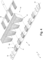
Figure 4 is a schematic perspective view of a unit of the packing machine ofFigure 1 for forming groups of cigarettes; - •
Figure 5 is a schematic plan view of the forming unit ofFigure 4 ; - •
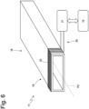
Figure 6 is a schematic perspective view of a feed duct of the forming unit inFigure 4 provided with an electromagnetic inductive sensor; - •
Figures 7 and 8 are plan views of a group of cigarettes in which all the cigarettes have the correct orientation and of a group of cigarettes in which one cigarette has the wrong orientation, respectively; - •
Figure 9 is a graph illustrating the time course of a signal generated by the electromagnetic sensor ofFigure 6 during the passage of the group of cigarettes ofFigure 7 and during the passage of the group of cigarettes ofFigure 8 ; - •
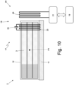
Figure 10 is a schematic cross-sectional view of a forming conveyor of the forming unit ofFigure 4 provided with a different type of electromagnetic sensor; - •
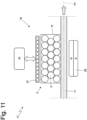
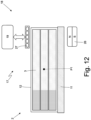
Figures 11 and12 are schematic, longitudinal and cross-sectional views of the forming conveyor of the forming unit ofFigure 4 provided with another type of electromagnetic sensor; and - •
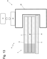
Figure 13 is a schematic cross-sectional view of the forming conveyor of the forming unit ofFigure 4 provided with a further type of electromagnetic sensor. -
Number 1 inFigure 1 indicates, as a whole, a rigid, hinged-lid cigarette packet comprising agroup 2 ofcigarettes 3 consisting of twentycigarettes 3 arranged in three rows (of seven-six-sevencigarettes 3 each, respectively). - As shown in
Figure 2 , eachcigarette 3 comprises a length oftobacco 4 wrapped in a respective tubular paper wrapping and afilter 5 which is stably connected to the length oftobacco 4 by means of a strap. Metal material is contained in the filter 5 (as for example described in patent applicationWO2005020723A1 ). Alternatively, as described, for example, in patent applicationUS4715389 , the metal material could also be contained in the length oftobacco 4. - In any case, that is, whether the metal material is contained in the
filter 5 or in the length oftobacco 4, this metal material may have different shapes. For example, this metal material can be granular, and therefore be dispersed in a more or less extended portion of thefilter 5 or of the length oftobacco 4, or it can be a linear or reticular element of elongated, tubular or cylindrical shape, or it can be shaped as a plurality of metal elements dispersed or aligned in thefilter 5 or in the length oftobacco 4. -
Figure 3 shows apacking machine 7 which makes thepacket 1 of cigarettes and comprises a formingunit 8 in which thegroups 2 ofcigarettes 3 are formed, awrapping unit 9 in which a sheet of wrapping material is wrapped around eachgroup 2 ofcigarettes 3 to form an inner wrapping, and awrapping unit 10 in which a blank is folded around each inner wrapping to form an outer container provided with a hinged lid, and thus complete the making of apacket 1 of cigarettes. - As shown in
Figures 4 and5 , the formingunit 8 comprises a formingconveyor belt 11, which supports a plurality ofpockets 12, each designed to receive and move acorresponding group 2 ofcigarettes 3. The formingconveyor 11 moves stepwise to feed eachpocket 12 along an annular forming path P1. - A feed station S is arranged along the forming path P1, in which four
groups 2 ofcigarettes 3 are simultaneously inserted (by moving along an insertion path P2 perpendicular to the forming path P1) intorespective pockets 12 which are stationary. Ahopper 13 is arranged in the feed station S, the former containing a mass ofcigarettes 3 and having fourtwin output mouths 14 at the bottom, through each of which agroup 2 ofcigarettes 3 is extracted and inserted into acorresponding pocket 12 which is stationary in front of theoutput mouth 14. Eachoutput mouth 14 is associated with acorresponding pushing element 15, which makes a linear reciprocating movement along the insertion path P2 to cyclically cross theoutput mouth 14 and axially push agroup 2 ofcigarettes 3 towards acorresponding pocket 12 which is stationary in front of theoutput mouth 14. - As shown in
Figure 5 , the formingunit 11 comprises fourtubular guide ducts 16, each of which is arranged in front of acorresponding output mouth 14 and guides the forward movement of agroup 3 of cigarettes which, once it exits theoutput mouth 14 of thehopper 13, must reach astationary pocket 12; that is, eachguide duct 16 connects anoutput mouth 14 to astationary pocket 12. As shown inFigure 6 , eachguide duct 16 has an internal passage channel having a substantially rectangular cross section which reproduces (with a small clearance) a cross section of thegroups 2 ofcigarettes 3; the passage channel of eachguide duct 16 may also comprise ribs which reproduce the circular shape of the cigarettes. - As shown in
Figure 6 , thepacking machine 7 comprises a (at least one)control unit 17 which allows the correct longitudinal orientation of theindividual cigarettes 3 in eachgroup 2 ofcigarettes 3 to be verified effectively and efficiently independently of the external appearance of thecigarettes 3; in other words, thecontrol unit 17 makes it possible to verify that allcigarettes 3 in eachgroup 2 ofcigarettes 3 have the same longitudinal orientation (as shown inFigure 7 ), that is, thecontrol unit 17 makes it possible to verify that in eachgroup 2 ofcigarettes 3 there are nocigarettes 3 oriented longitudinally in a different way than (opposite to) the other cigarettes 3 (as shown inFigure 8 ). - In the embodiment shown in
Figure 5 , fourtwin control units 17 are provided, each of which is coupled to acorresponding guide duct 16 and is arranged along the corresponding insertion path P2. - As shown in
Figure 6 , eachcontrol unit 17 comprises asensor 18, which is arranged in a fixed position along the insertion path P2 followed by thegroups 2 ofcigarettes 3, and aprocessing device 19, which is coupled to thesensor 18 and is configured to establish whether, depending on the signals provided by thesensor 18, thegroup 2 ofcigarettes 3 moving along the insertion path P2 has or has not all thecigarettes 3 with a same longitudinal orientation. In eachcontrol unit 17, thesensor 18 is an electromagnetic sensor and is sensitive to the presence of the metal material contained in thecigarettes 3. In the embodiment shown inFigure 6 , in eachcontrol unit 17 theprocessing device 19 reads thesensor 18 when agroup 2 ofcigarettes 3 is moving near (in proximity to) thesensor 18, that is, when thegroup 2 ofcigarettes 3 is moving (along the insertion path P2) with respect to thesensor 18. According to an alternative embodiment, in eachcontrol unit 17 theprocessing device 19 reads thesensor 18 when agroup 2 ofcigarettes 3 is stationary near (in proximity to) thesensor 18. - Preferably and as shown in
Figure 9 , in eachcontrol unit 17 theprocessing device 19 is configured to: detect a time development x(t) of a parameter x when thesensor 18 is in proximity to agroup 2 of cigarettes 3 (which may be moving or stationary with respect to the sensor 18); compare the detected time development x(t) with a sample time development corresponding to asample group 2 ofcigarettes 3 in which all thecigarettes 3 have a same longitudinal orientation; and establish whether thegroup 2 ofcigarettes 3 has or has not all thecigarettes 3 with a same longitudinal orientation depending on the result of the comparison. In other words, if the detected time development x(t) is sufficiently similar to (i.e., not too different from) the sample development, then all thecigarettes 3 of thegroup 2 ofcigarettes 3 have the same longitudinal orientation, whereas if the detected time development x(t) is sufficiently different from the sample development (i.e., not sufficiently similar to the sample development) at least onecigarette 3 of thegroup 2 ofcigarettes 3 has a different longitudinal orientation (an incorrect orientation, i.e., opposite to the other cigarettes 3). - In
Figure 9 , the solid line shows a time development x(t) of the parameter x when thesensor 18 is close to agroup 2 ofcigarettes 3 in which all thecigarettes 3 of thegroup 2 ofcigarettes 3 have the same longitudinal orientation, whereas the dashed line shows a time development x(t) of the parameter x when thesensor 18 is close to agroup 2 ofcigarettes 3 in which at least onecigarette 3 of thegroup 2 ofcigarettes 3 has a different longitudinal orientation (an incorrect orientation, i.e., opposite to the other cigarettes 3). In the embodiment shown inFigure 6 , eachsensor 18 comprises anelectric oscillator circuit 20 having at least one quantity which is influenced by a proximity to the metal material contained in thefilters 5 of thecigarettes 3, and apower supply 21 which applies a variable electrical voltage to theelectric oscillator circuit 20 and is connected to theprocessing device 19. Theelectric oscillator circuit 20 comprises an inductor (i.e., an electrical component that generates a magnetic field when an electric current flows therethrough); at least one quantity which is influenced by a proximity to the metal material contained in thefilters 5 of thecigarettes 3 is (directly or indirectly), for example, the inductance of the inductor. - In the embodiment shown in
Figure 6 , in eachsensor 18 the inductor consists of a single coil 22 (that is, theelectric oscillator circuit 20 comprises a single coil 22), which is directly (galvanically) connected to thepower supply 21 and is arranged in a fixed position along the corresponding insertion path P2. In particular, eachcoil 22 is wound around thecorresponding guide duct 16, and thus around the corresponding insertion path P2, so that agroup 2 ofcigarettes 3 moving along theguide duct 16 and therefore along the insertion path P2 passes inside the coil 22 (that is, it longitudinally crosses the coil). Preferably, each sensor 18 (or each coil 22) is arranged around thecorresponding guide duct 16 in the vicinity of the end facing the forming conveyor 11 (and therefore opposite to the end facing the hopper 13); in this way, each sensor 18 (or the coil 22) is arranged in an area of theguide duct 16 which is travelled by thegroup 2 ofcigarettes 3 at a slower forward speed (when the pushingelement 15 reaches the end of theguide duct 16 facing the formingconveyor 11, its speed drops to zero and its direction of motion is reverted). It is understood that each sensor 18 (that is, the coil 22) can be arranged in any area of theduct 16. - In this embodiment, the presence and position of the metal material inside each coil 22 (i.e., inside each inductor) is "sensed" by the
power supply 21, for example, as a change in the inductance (which involves a consequent change in the reactance, or impedance), a change in the quality factor or a change in the resonance frequency. Accordingly, the parameter x of which the time development x(t) is detected (shown inFigure 9 ) can be, for example, the inductance of theelectric oscillator circuit 20 or the quality factor of theelectric oscillator circuit 20. - In the embodiment shown in
Figure 6 , thecoils 22 of thevarious sensors 18 could influence each other, thus distorting the readings; in order to avoid this drawback, it is possible to differentiate the working frequencies of theelectric oscillator circuits 20 of the various sensors 18 (especially of the adjacent electric oscillator circuits 20); that is, theelectric oscillator circuits 20 of thevarious sensors 18 have oscillation frequencies that are different from each other. - The embodiment shown in
Figure 6 has an extreme reading speed, is only sensitive to the presence of the metal material (that is, it is not affected in any way by the other components of the cigarettes such as tobacco, filters, paper etc.), and is also capable of operating when the metal material is not magnetic (i.e., not ferromagnetic). - In the embodiment shown in
Figure 10 , asingle control unit 17 is provided, which is coupled to the formingconveyor 11 and arranged along the forming path P1 (instead of fourcontrol units 17 coupled to the respective guide ducts 16). - In the embodiment shown in
Figure 10 , theelectric oscillator circuit 20 of thesensor 18 comprises a plurality ofcoils 23, each of which is galvanically separated from and independent of thepower supply 21, is wound around acorresponding pocket 12 which moves thegroup 2 ofcigarettes 3 along the forming path P1, and is preferably shortcircuited by a capacitor 24 (so as to form a resonant L/C circuit); furthermore, theelectric oscillator circuit 20 of thesensor 18 comprises asingle coil 25, which is directly (galvanically) connected to thepower supply 21 and arranged in a fixed position along the forming path P1, so as to be electromagnetically coupled to eachcoil 23 when thecorresponding pocket 12 passes near thecoil 25. - In this embodiment too, the presence and position of the metal material inside each coil 23 (i.e., inside each inductor) is "sensed" by the
power supply 21, for example, as a change in the inductance (which involves a consequent change in the reactance, or impedance) a change in the quality factor or a change in the resonance frequency. Accordingly, the parameter x of which the time development x(t) is detected can be, for example, the inductance of theelectric oscillator circuit 20 or the quality factor of theelectric oscillator circuit 20. From a practical point of view, thepower supply 21 can generate in thecoil 25 an electric oscillator signal (even of the impulsive type and which therefore tends to be naturally dampened in time), which undergoes variations (in terms of amplitude, duration, slope, frequency) due to the presence of the metal material carried by thecigarettes 3 inside thecoil 23. - In other words, in the embodiment shown in
Figure 10 , eachcoil 23 is part of a movable resonant circuit carried by acorresponding pocket 12, whereas thecoil 25 is part of an excitation and measurement circuit arranged in a fixed position, for example, alongside the formingconveyor 11. - In the embodiment shown in
Figures 11 and12 , asingle control unit 17 is provided, which is coupled to the formingconveyor 11 and arranged along the forming path P1 (as in the embodiment shown inFigure 10 ); in this embodiment, thesensor 18 comprises a magnet 26 (permanent or equipped with an excitable solenoid) arranged in a fixed position on one side of the forming path P1 (i.e., on one side of the forming conveyor 11) to generate a static magnetic field, and an array ofelements 27 sensitive to the magnetic field (magneto resistors, GMRs,...), which are arranged in a fixed position on the opposite side of the forming path P1 (i.e., on the opposite side of the forming conveyor 11) and are connected to theprocessing device 19. - In use, the array of
sensitive elements 27 is capable of detecting a change in the intensity of the static magnetic field generated by themagnet 26 due to the presence and position of themetal elements 6 in thecigarettes 3 of thegroup 2 ofcigarettes 3. - As an alternative to what is shown in
Figures 11 and12 , thecontrol unit 17 can be arranged in a fixed position along the insertion path P2. Preferably, themagnet 26 and the array ofsensitive elements 27 are arranged on opposite sides of theguide duct 16 in the vicinity of the end facing the formingconveyor 11. In this embodiment, thegroup 2 ofcigarettes 3 longitudinally crosses the array ofsensitive elements 27, that is, the array ofsensitive elements 27 is arranged orthogonal to the forward movement of thegroup 2 of cigarettes. - In the embodiment shown in
Figure 13 , asingle control unit 17 is provided, which is coupled to the formingconveyor 11 and arranged along the forming path P1 (as in the embodiment shown inFigure 10 ); in this embodiment, thesensor 18 comprises a resonatingcavity 28, which is arranged along the forming path P1 (i.e., along the forming conveyor 11) to be crossed by thegroup 2 ofcigarettes 3, and a microwave emitter/receiver 29, which is designed to emit and receive microwaves inside the resonatingcavity 28 and is connected to theprocessing device 19. - It should be noted that, if the
group 2 of cigarettes crosses thesensor 18 longitudinally, preferably this sensor 18 (i.e., the coil 22) has a smaller width than the length of theportion 5 containing the metal material. In other words, with reference toFigure 6 , thecoil 22 has a width (that is, an extension in the direction parallel to the insertion path P2) smaller than the length of thefilter 5. - It should be noted that, if the
group 2 of cigarettes crosses thesensor 18 transversely (Figure 13 ) or passes near thesensor 18 with a transverse movement (Figure 10 or11 ), or if the measurement is static, then thesensor 18 is positioned in the area of thegroup 2 of cigarettes where no metal material should be contained. - In the embodiments shown herein, the
control unit 17 is coupled to the formingunit 8 to control thegroups 2 ofcigarettes 3 before starting the wrapping of the wrapping materials and thus to be able to discard thedefective groups 2 ofcigarettes 3 before starting the wrapping of the wrapping materials. According to other embodiments, not shown, thecontrol unit 17 is coupled to thewrapping unit 9, to thewrapping unit 10, or to an output conveyor arranged downstream of thewrapping unit 10; in this case, thegroups 2 ofcigarettes 3 are checked after the wrapping of at least part of the wrapping materials, and thus the semi-finished orfinished packets 1 of cigarettes containingdefective groups 2 ofcigarettes 3 are discarded. - In the embodiment shown in the accompanying drawings, each
cigarette 3 comprises (at least) metal material dispersed in thefilter 5, which has the function of increasing the filtering capacity (as described, for example, in patent applicationWO2005020723A1 ). According to a different, equivalent embodiment, eachcigarette 3 comprises an (at least one) annular metal element, which is arranged on the outer surface of the strap connecting thefilter 5 to the length of tobacco 4 (which is therefore in sight, i.e., visible from the outside) and has an aesthetic function; this annular metal element could be laminated on the paper band from which the connection straps are formed or could be printed (typically by jet printing technology) on the paper band from which the connection straps are formed. - According to a further, equivalent embodiment, each
cigarette 2 comprises a (at least one) metal element which, instead of being arranged inside thefilter 5, is arranged inside the length of tobacco 4 (as for example described in patentUS4715389A ). - In all the possible embodiments described above (which can also optionally be combined together), the
cigarette 3 comprises a (at least one) portion containing metal material arranged asymmetrically with respect to a longitudinal center line of thecigarette 3. - In the embodiment shown in the accompanying drawings, the
group 2 comprisesconventional cigarettes 3, therefore each provided with a length oftobacco 4 intended for combustion and afilter 5. Alternatively, thegroup 2 may comprisecigarettes 3 in which thefilter 5 and/or the length oftobacco 4 is of the multi-segment type; in this case, the metal material may be contained in one or more segments of thefilter 5 and/or of the length oftobacco 4. - The embodiments described herein may be combined with each other without departing from the scope of protection of the present invention.
- The
control unit 17 described above has many advantages. - Firstly, the
control unit 17 described above allows the correct longitudinal orientation of theindividual cigarettes 3 in agroup 2 ofcigarettes 3 to be verified effectively and efficiently, independently of the external appearance of the cigarettes 3 (i.e., without using cameras or similar optical sensors). - Moreover, the
control unit 17 described above is fast enough to operate correctly even in a fast packing machine 7 (for example, capable of producing 800-1,000packets 1 of cigarettes per minute); that is, thecontrol unit 17 described above is able to verify in (much) less than one hundredth of a second the correct longitudinal orientation of theindividual cigarettes 3 in agroup 2 ofcigarettes 3 even when thegroup 2 ofcigarettes 3 is moving (rapidly). - The
control unit 17 described above is particularly compact and therefore can also be installed in an existingpacking machine 7 without undue difficulty. - Finally, the
control unit 17 described above is particularly simple and inexpensive to manufacture, since it uses structurally simple and inexpensive components (coils, magnets, capacitors, small electronic circuits).
Claims (10)
- A control unit (17) configured to control a group (2) of smoking articles (3), each comprising a portion (5) containing metal material; the control unit (17) comprises:an electromagnetic sensor (18), which is arranged along a path followed by the group (2) of smoking articles (3) and is sensitive to the presence of the metal material contained in the portion (5) of the smoking articles (3); anda processing device (19), which is coupled to the sensor (18) and is configured to establish whether, depending on the signals provided by the sensor (18), the group (2) of smoking articles (3) moving along the path has or has not all the smoking articles (3) with a same longitudinal orientation;wherein the electromagnetic sensor (18) comprises: an electric oscillator circuit (20) having at least one quantity, in particular an inductance, which is influenced by a proximity with the metal material contained in the portion (5) of the smoking articles (3);and a power supply (21), which applies an electric voltage, in particular an AC voltage, to the electric oscillator circuit (20) and is connected to the processing device (19);the control unit (17) is characterized in that the electric oscillator circuit (20) comprises one single coil (22), which is connected to the power supply (21), is arranged in a fixed position along the path, and is wound around the path so that the group (2) of smoking articles (3) moving along the path longitudinally passes inside the coil (22).
- The control unit (17) according to claim 1, wherein the processing device (19) reads the sensor (18) when the group (2) of smoking articles (3) is moving in the area of the sensor (18).
- The control unit (17) according to claim 1, wherein the processing device (19) reads the sensor (18) when the group (2) of smoking articles (3) is standing still in the area of the sensor (18).
- The control unit (17) according to claim 1, 2 or 3, wherein the processing device (19) is configured to:detect a time development of a parameter (x) when the sensor (18) is in proximity to the group (2) of smoking articles (3);compare the detected time development with a sample time development corresponding to a sample group (2) of smoking articles (3), in which all the smoking articles (3) have a same longitudinal orientation; andestablish whether the group (2) of smoking articles (3) has or has not all the smoking articles (3) with a same longitudinal orientation depending on the result of the comparison.
- The control unit (17) according to any one of the claims from 1 to 4, wherein:there is a plurality of electric oscillator circuits (20) arranged along respective paths followed by corresponding groups (2) of smoking articles (3); andsaid plurality of electric oscillator circuits (20) have different work frequencies.
- A packing machine to manufacture a pack of cigarettes around a group (2) of smoking articles (3), each comprising a portion (5) containing metal material; the packing machine comprises:conveyor means, which move the group (2) of smoking articles (3) along a path; anda control unit (17), which is coupled to the conveyor and is manufactured according to any one of the claims from 1 to 5.
- The packing machine according to claim 6 and comprising:a forming conveyor belt (11), which supports a plurality of pockets (12), each designed to receive and move a corresponding group (2) of smoking articles (3) along a forming path (P1);a hopper (13), which contains a mass of smoking articles (3) and has, at the bottom, at least one output mouth (14);at least one pushing element (15), which makes a linear reciprocating movement along an insertion path (P2) and is designed to cyclically cross the output mouth (14) so as to extract a group (2) of smoking articles (3) from the output mouth (14) and insert the group (2) of smoking articles (3) into a corresponding pocket (12) standing still; anda tubular guide duct (16), which is arranged along the insertion path (P2) between the output mouth (14) and the forming conveyor (11);wherein the control unit (17) is coupled to the guide duct (16) and is arranged along the insertion path (P2).
- The packing machine according to claim 7, wherein the sensor (18) of the control unit (17) is arranged around the guide duct (16) in the area of an end facing the forming conveyor (11).
- The packing machine according to claim 6 and comprising:a forming conveyor belt (11), which supports a plurality of pockets (12), each designed to receive and move a corresponding group (2) of smoking articles (3) along a forming path (P1);a hopper (13), which contains a mass of smoking articles (3) and has, at the bottom, at least one output mouth (14); andat least one pushing element (15), which makes a linear reciprocating movement along an insertion path (P2) and is designed to cyclically cross the output mouth (14) so as to extract a group (2) of smoking articles (3) from the output mouth (14) and insert the group (2) of smoking articles (3) into a corresponding pocket (12) standing still;wherein the control unit (17) is coupled to the forming conveyor (11) and is arranged along the forming path (P1).
- A control method to control a group (2) of smoking articles (3), each comprising a portion (5) containing metal material; the control method comprises the steps of:moving the group (2) of smoking articles (3) along a path;establishing, by means of a processing device (19) coupled to an electromagnetic sensor (18) arranged along the path and depending on the signals provided by the sensor (18), whether the group (2) of smoking articles (3) moving along the path has or has not all the smoking articles (3) with a same longitudinal orientation; anddetecting the presence of the metal material contained in the portion (5) of the smoking articles (3) by means of the electromagnetic sensor (18);wherein the electromagnetic sensor (18) comprises: an electric oscillator circuit (20) having at least one quantity, in particular an inductance, which is influenced by a proximity with the metal material contained in the portion (5) of the smoking articles (3); and a power supply (21), which applies an electric voltage, in particular an AC voltage, to the electric oscillator circuit (20) and is connected to the processing device (19);the control method is characterized in that the electric oscillator circuit (20) comprises one single coil (22), which is connected to the power supply (21), is arranged in a fixed position along the path, and is wound around the path so that the group (2) of smoking articles (3) moving along the path longitudinally passes inside the coil (22).
Applications Claiming Priority (2)
| Application Number | Priority Date | Filing Date | Title |
|---|---|---|---|
| IT102020000001870A IT202000001870A1 (en) | 2020-01-31 | 2020-01-31 | Control unit and method of a group of smoking articles |
| PCT/IB2021/050722 WO2021152531A1 (en) | 2020-01-31 | 2021-01-29 | Control unit and method for controlling a group of smoking articles |
Publications (2)
| Publication Number | Publication Date |
|---|---|
| EP4096445A1 EP4096445A1 (en) | 2022-12-07 |
| EP4096445B1 true EP4096445B1 (en) | 2024-08-21 |
Family
ID=70480464
Family Applications (1)
| Application Number | Title | Priority Date | Filing Date |
|---|---|---|---|
| EP21708366.6A Active EP4096445B1 (en) | 2020-01-31 | 2021-01-29 | Control unit and method for controlling a group of smoking articles |
Country Status (4)
| Country | Link |
|---|---|
| EP (1) | EP4096445B1 (en) |
| KR (1) | KR20220133276A (en) |
| IT (1) | IT202000001870A1 (en) |
| WO (1) | WO2021152531A1 (en) |
Citations (5)
| Publication number | Priority date | Publication date | Assignee | Title |
|---|---|---|---|---|
| DE3714009A1 (en) * | 1987-04-27 | 1988-11-10 | Hauni Werke Koerber & Co Kg | METAL DETECTOR |
| DE4424058C1 (en) * | 1994-07-08 | 1995-10-19 | Mesutronic Geraetebau Gmbh | Recognition signal generator for detecting metallic parts in product on conveyor belt |
| WO2018033430A1 (en) * | 2016-08-15 | 2018-02-22 | Hauni Maschinenbau Gmbh | Measuring apparatus and method for detecting electrically conductive elements in products and a machine for producing products of the tobacco-processing industry |
| EP3474451A1 (en) * | 2017-10-19 | 2019-04-24 | Imst Gmbh | Sensor device, detection method for a sensor device and use of a sensor device |
| DE102018106825A1 (en) * | 2018-03-22 | 2019-09-26 | Hauni Maschinenbau Gmbh | Conveyor for rod-shaped smoking articles |
Family Cites Families (9)
| Publication number | Priority date | Publication date | Assignee | Title |
|---|---|---|---|---|
| US4715389A (en) | 1986-09-15 | 1987-12-29 | R. J. Reynolds Tobacco Company | Cigarette |
| IT1279728B1 (en) | 1995-09-25 | 1997-12-16 | Gd Spa | METHOD AND DEVICE FOR THE TRAINING AND TRANSFER OF GROUPS OF CIGARETTES IN A PACKAGING MACHINE WITH MULTIPLE LINES OF |
| DE19947282A1 (en) * | 1999-09-30 | 2001-04-05 | Hauni Maschinenbau Ag | Process for the production of packs by wrapping a packaged product |
| ITBO20000577A1 (en) | 2000-10-03 | 2002-04-03 | Gd Spa | AUTOMATIC MACHINE |
| DE10252914A1 (en) * | 2002-10-10 | 2004-04-22 | Focke Gmbh & Co. Kg | Method and device for checking the content of a (closed) package |
| EP1410991A3 (en) * | 2002-10-10 | 2005-12-14 | Focke & Co. (GmbH & Co. KG) | Method and apparatus for checking the content of a (closed) package |
| EP1711077A1 (en) | 2003-09-03 | 2006-10-18 | Resys AB | Tobacco smoke filter |
| PL230779B1 (en) * | 2016-06-03 | 2018-12-31 | Int Tobacco Machinery Poland Spolka Z Ograniczona Odpowiedzialnoscia | Urządzenie do identyfikacji parametrów fizycznych artykułów prętopodobnych przemysłu tytoniowego |
| PL233097B1 (en) * | 2016-06-10 | 2019-09-30 | Int Tobacco Machinery Poland Spolka Z Ograniczona Odpowiedzialnoscia | Device for defining positioning of the insert in the rod-like articles of tobacco industry |
-
2020
- 2020-01-31 IT IT102020000001870A patent/IT202000001870A1/en unknown
-
2021
- 2021-01-29 EP EP21708366.6A patent/EP4096445B1/en active Active
- 2021-01-29 KR KR1020227029759A patent/KR20220133276A/en active Pending
- 2021-01-29 WO PCT/IB2021/050722 patent/WO2021152531A1/en not_active Ceased
Patent Citations (5)
| Publication number | Priority date | Publication date | Assignee | Title |
|---|---|---|---|---|
| DE3714009A1 (en) * | 1987-04-27 | 1988-11-10 | Hauni Werke Koerber & Co Kg | METAL DETECTOR |
| DE4424058C1 (en) * | 1994-07-08 | 1995-10-19 | Mesutronic Geraetebau Gmbh | Recognition signal generator for detecting metallic parts in product on conveyor belt |
| WO2018033430A1 (en) * | 2016-08-15 | 2018-02-22 | Hauni Maschinenbau Gmbh | Measuring apparatus and method for detecting electrically conductive elements in products and a machine for producing products of the tobacco-processing industry |
| EP3474451A1 (en) * | 2017-10-19 | 2019-04-24 | Imst Gmbh | Sensor device, detection method for a sensor device and use of a sensor device |
| DE102018106825A1 (en) * | 2018-03-22 | 2019-09-26 | Hauni Maschinenbau Gmbh | Conveyor for rod-shaped smoking articles |
Also Published As
| Publication number | Publication date |
|---|---|
| WO2021152531A1 (en) | 2021-08-05 |
| IT202000001870A1 (en) | 2021-07-31 |
| EP4096445A1 (en) | 2022-12-07 |
| KR20220133276A (en) | 2022-10-04 |
Similar Documents
| Publication | Publication Date | Title |
|---|---|---|
| JP6435126B2 (en) | Apparatus and method for inspecting bar-shaped articles in the tobacco processing industry | |
| KR102431953B1 (en) | Measuring devices and methods for detecting electrically conductive elements in products, and machines for producing products for the tobacco processing industry | |
| CN112672658B (en) | Aerosol generating systems and aerosol generating devices | |
| CN106455678B (en) | Microwave measuring device, assembly and method for testing rod-shaped articles or material strips of the tobacco processing industry, and machine of the tobacco processing industry | |
| CN102196737B (en) | Inspection system for a smoking article having an object inserted therein, and associated method | |
| CN103504473B (en) | The method and apparatus that the bar heterogeneity of the material strips of the tobacco industry is identified | |
| CN105249529B (en) | The detection method of the machine of tobacco, roller system and bar form articles | |
| US7793664B2 (en) | Apparatus and method for detection and segregation of faulty cigarettes | |
| EP4096445B1 (en) | Control unit and method for controlling a group of smoking articles | |
| KR102546260B1 (en) | Methods and systems for manufacturing multi-segment products for the tobacco industry | |
| CN103960773A (en) | Measuring Device, Machine And Method For The Tobacco Processing Industry | |
| JPS6112672B2 (en) | ||
| GB2254240A (en) | Method of and apparatus for perforating cigarette paper | |
| JP2022517777A (en) | Methods for determining aerosol generators, aerosol-producing articles, and data related to aerosol-producing articles. | |
| CN107692306A (en) | For identify and/or check be inserted into tobacco rod or rod-shaped articles in object method and apparatus | |
| JP2005053585A (en) | Automatic machine for processing having position transducer with hall effect sensor | |
| ITBO20060585A1 (en) | DEVICE FOR THE DETECTION OF A CHARACTERISTIC OF A FIBER MATERIAL. | |
| JP2000350570A (en) | Inspection of cigarette and device therefor | |
| EP1793207B1 (en) | Eddy current sensor and sensor coil for the same | |
| KR20230091948A (en) | Inspection device for quality control of rod-shaped articles | |
| US3914989A (en) | Method and apparatus for testing cigarettes or the like | |
| CN213344351U (en) | Aerosol generating device and sensor | |
| EP4231859B1 (en) | Method of inspection of rod shaped articles | |
| EP3853595A1 (en) | Electromagnetic detector for detecting properties of products of the tobacco industry | |
| JP2025517995A (en) | Electromagnetic detectors for detecting the characteristics of products in the tobacco industry |
Legal Events
| Date | Code | Title | Description |
|---|---|---|---|
| STAA | Information on the status of an ep patent application or granted ep patent |
Free format text: STATUS: UNKNOWN |
|
| STAA | Information on the status of an ep patent application or granted ep patent |
Free format text: STATUS: THE INTERNATIONAL PUBLICATION HAS BEEN MADE |
|
| PUAI | Public reference made under article 153(3) epc to a published international application that has entered the european phase |
Free format text: ORIGINAL CODE: 0009012 |
|
| STAA | Information on the status of an ep patent application or granted ep patent |
Free format text: STATUS: REQUEST FOR EXAMINATION WAS MADE |
|
| 17P | Request for examination filed |
Effective date: 20220725 |
|
| AK | Designated contracting states |
Kind code of ref document: A1 Designated state(s): AL AT BE BG CH CY CZ DE DK EE ES FI FR GB GR HR HU IE IS IT LI LT LU LV MC MK MT NL NO PL PT RO RS SE SI SK SM TR |
|
| DAV | Request for validation of the european patent (deleted) | ||
| DAX | Request for extension of the european patent (deleted) | ||
| TPAC | Observations filed by third parties |
Free format text: ORIGINAL CODE: EPIDOSNTIPA |
|
| P01 | Opt-out of the competence of the unified patent court (upc) registered |
Effective date: 20230529 |
|
| STAA | Information on the status of an ep patent application or granted ep patent |
Free format text: STATUS: EXAMINATION IS IN PROGRESS |
|
| 17Q | First examination report despatched |
Effective date: 20230731 |
|
| REG | Reference to a national code |
Ref country code: DE Ref legal event code: R079 Free format text: PREVIOUS MAIN CLASS: A24C0005340000 Ipc: B65B0019200000 Ref country code: DE Ref legal event code: R079 Ref document number: 602021017507 Country of ref document: DE Free format text: PREVIOUS MAIN CLASS: A24C0005340000 Ipc: B65B0019200000 |
|
| RIC1 | Information provided on ipc code assigned before grant |
Ipc: B65B 19/32 20060101ALI20240125BHEP Ipc: A24C 5/34 20060101ALI20240125BHEP Ipc: B65B 57/10 20060101ALI20240125BHEP Ipc: B65B 35/40 20060101ALI20240125BHEP Ipc: B65B 19/20 20060101AFI20240125BHEP |
|
| GRAP | Despatch of communication of intention to grant a patent |
Free format text: ORIGINAL CODE: EPIDOSNIGR1 |
|
| STAA | Information on the status of an ep patent application or granted ep patent |
Free format text: STATUS: GRANT OF PATENT IS INTENDED |
|
| INTG | Intention to grant announced |
Effective date: 20240313 |
|
| GRAS | Grant fee paid |
Free format text: ORIGINAL CODE: EPIDOSNIGR3 |
|
| GRAA | (expected) grant |
Free format text: ORIGINAL CODE: 0009210 |
|
| STAA | Information on the status of an ep patent application or granted ep patent |
Free format text: STATUS: THE PATENT HAS BEEN GRANTED |
|
| AK | Designated contracting states |
Kind code of ref document: B1 Designated state(s): AL AT BE BG CH CY CZ DE DK EE ES FI FR GB GR HR HU IE IS IT LI LT LU LV MC MK MT NL NO PL PT RO RS SE SI SK SM TR |
|
| REG | Reference to a national code |
Ref country code: GB Ref legal event code: FG4D |
|
| REG | Reference to a national code |
Ref country code: CH Ref legal event code: EP |
|
| REG | Reference to a national code |
Ref country code: DE Ref legal event code: R096 Ref document number: 602021017507 Country of ref document: DE |
|
| REG | Reference to a national code |
Ref country code: IE Ref legal event code: FG4D |
|
| REG | Reference to a national code |
Ref country code: LT Ref legal event code: MG9D |
|
| REG | Reference to a national code |
Ref country code: NL Ref legal event code: MP Effective date: 20240821 |
|
| PG25 | Lapsed in a contracting state [announced via postgrant information from national office to epo] |
Ref country code: NO Free format text: LAPSE BECAUSE OF FAILURE TO SUBMIT A TRANSLATION OF THE DESCRIPTION OR TO PAY THE FEE WITHIN THE PRESCRIBED TIME-LIMIT Effective date: 20241121 |
|
| REG | Reference to a national code |
Ref country code: AT Ref legal event code: MK05 Ref document number: 1715296 Country of ref document: AT Kind code of ref document: T Effective date: 20240821 |
|
| PG25 | Lapsed in a contracting state [announced via postgrant information from national office to epo] |
Ref country code: PT Free format text: LAPSE BECAUSE OF FAILURE TO SUBMIT A TRANSLATION OF THE DESCRIPTION OR TO PAY THE FEE WITHIN THE PRESCRIBED TIME-LIMIT Effective date: 20241223 Ref country code: GR Free format text: LAPSE BECAUSE OF FAILURE TO SUBMIT A TRANSLATION OF THE DESCRIPTION OR TO PAY THE FEE WITHIN THE PRESCRIBED TIME-LIMIT Effective date: 20241122 Ref country code: NL Free format text: LAPSE BECAUSE OF FAILURE TO SUBMIT A TRANSLATION OF THE DESCRIPTION OR TO PAY THE FEE WITHIN THE PRESCRIBED TIME-LIMIT Effective date: 20240821 Ref country code: FI Free format text: LAPSE BECAUSE OF FAILURE TO SUBMIT A TRANSLATION OF THE DESCRIPTION OR TO PAY THE FEE WITHIN THE PRESCRIBED TIME-LIMIT Effective date: 20240821 Ref country code: PL Free format text: LAPSE BECAUSE OF FAILURE TO SUBMIT A TRANSLATION OF THE DESCRIPTION OR TO PAY THE FEE WITHIN THE PRESCRIBED TIME-LIMIT Effective date: 20240821 |
|
| PG25 | Lapsed in a contracting state [announced via postgrant information from national office to epo] |
Ref country code: BG Free format text: LAPSE BECAUSE OF FAILURE TO SUBMIT A TRANSLATION OF THE DESCRIPTION OR TO PAY THE FEE WITHIN THE PRESCRIBED TIME-LIMIT Effective date: 20240821 |
|
| PG25 | Lapsed in a contracting state [announced via postgrant information from national office to epo] |
Ref country code: LV Free format text: LAPSE BECAUSE OF FAILURE TO SUBMIT A TRANSLATION OF THE DESCRIPTION OR TO PAY THE FEE WITHIN THE PRESCRIBED TIME-LIMIT Effective date: 20240821 |
|
| PG25 | Lapsed in a contracting state [announced via postgrant information from national office to epo] |
Ref country code: AT Free format text: LAPSE BECAUSE OF FAILURE TO SUBMIT A TRANSLATION OF THE DESCRIPTION OR TO PAY THE FEE WITHIN THE PRESCRIBED TIME-LIMIT Effective date: 20240821 Ref country code: IS Free format text: LAPSE BECAUSE OF FAILURE TO SUBMIT A TRANSLATION OF THE DESCRIPTION OR TO PAY THE FEE WITHIN THE PRESCRIBED TIME-LIMIT Effective date: 20241221 |
|
| PG25 | Lapsed in a contracting state [announced via postgrant information from national office to epo] |
Ref country code: HR Free format text: LAPSE BECAUSE OF FAILURE TO SUBMIT A TRANSLATION OF THE DESCRIPTION OR TO PAY THE FEE WITHIN THE PRESCRIBED TIME-LIMIT Effective date: 20240821 |
|
| PG25 | Lapsed in a contracting state [announced via postgrant information from national office to epo] |
Ref country code: ES Free format text: LAPSE BECAUSE OF FAILURE TO SUBMIT A TRANSLATION OF THE DESCRIPTION OR TO PAY THE FEE WITHIN THE PRESCRIBED TIME-LIMIT Effective date: 20240821 Ref country code: RS Free format text: LAPSE BECAUSE OF FAILURE TO SUBMIT A TRANSLATION OF THE DESCRIPTION OR TO PAY THE FEE WITHIN THE PRESCRIBED TIME-LIMIT Effective date: 20241121 |
|
| PG25 | Lapsed in a contracting state [announced via postgrant information from national office to epo] |
Ref country code: RS Free format text: LAPSE BECAUSE OF FAILURE TO SUBMIT A TRANSLATION OF THE DESCRIPTION OR TO PAY THE FEE WITHIN THE PRESCRIBED TIME-LIMIT Effective date: 20241121 Ref country code: PT Free format text: LAPSE BECAUSE OF FAILURE TO SUBMIT A TRANSLATION OF THE DESCRIPTION OR TO PAY THE FEE WITHIN THE PRESCRIBED TIME-LIMIT Effective date: 20241223 Ref country code: PL Free format text: LAPSE BECAUSE OF FAILURE TO SUBMIT A TRANSLATION OF THE DESCRIPTION OR TO PAY THE FEE WITHIN THE PRESCRIBED TIME-LIMIT Effective date: 20240821 Ref country code: NO Free format text: LAPSE BECAUSE OF FAILURE TO SUBMIT A TRANSLATION OF THE DESCRIPTION OR TO PAY THE FEE WITHIN THE PRESCRIBED TIME-LIMIT Effective date: 20241121 Ref country code: NL Free format text: LAPSE BECAUSE OF FAILURE TO SUBMIT A TRANSLATION OF THE DESCRIPTION OR TO PAY THE FEE WITHIN THE PRESCRIBED TIME-LIMIT Effective date: 20240821 Ref country code: LV Free format text: LAPSE BECAUSE OF FAILURE TO SUBMIT A TRANSLATION OF THE DESCRIPTION OR TO PAY THE FEE WITHIN THE PRESCRIBED TIME-LIMIT Effective date: 20240821 Ref country code: IS Free format text: LAPSE BECAUSE OF FAILURE TO SUBMIT A TRANSLATION OF THE DESCRIPTION OR TO PAY THE FEE WITHIN THE PRESCRIBED TIME-LIMIT Effective date: 20241221 Ref country code: HR Free format text: LAPSE BECAUSE OF FAILURE TO SUBMIT A TRANSLATION OF THE DESCRIPTION OR TO PAY THE FEE WITHIN THE PRESCRIBED TIME-LIMIT Effective date: 20240821 Ref country code: GR Free format text: LAPSE BECAUSE OF FAILURE TO SUBMIT A TRANSLATION OF THE DESCRIPTION OR TO PAY THE FEE WITHIN THE PRESCRIBED TIME-LIMIT Effective date: 20241122 Ref country code: FI Free format text: LAPSE BECAUSE OF FAILURE TO SUBMIT A TRANSLATION OF THE DESCRIPTION OR TO PAY THE FEE WITHIN THE PRESCRIBED TIME-LIMIT Effective date: 20240821 Ref country code: ES Free format text: LAPSE BECAUSE OF FAILURE TO SUBMIT A TRANSLATION OF THE DESCRIPTION OR TO PAY THE FEE WITHIN THE PRESCRIBED TIME-LIMIT Effective date: 20240821 Ref country code: BG Free format text: LAPSE BECAUSE OF FAILURE TO SUBMIT A TRANSLATION OF THE DESCRIPTION OR TO PAY THE FEE WITHIN THE PRESCRIBED TIME-LIMIT Effective date: 20240821 Ref country code: AT Free format text: LAPSE BECAUSE OF FAILURE TO SUBMIT A TRANSLATION OF THE DESCRIPTION OR TO PAY THE FEE WITHIN THE PRESCRIBED TIME-LIMIT Effective date: 20240821 |
|
| PGFP | Annual fee paid to national office [announced via postgrant information from national office to epo] |
Ref country code: DE Payment date: 20250129 Year of fee payment: 5 |
|
| PG25 | Lapsed in a contracting state [announced via postgrant information from national office to epo] |
Ref country code: RO Free format text: LAPSE BECAUSE OF FAILURE TO SUBMIT A TRANSLATION OF THE DESCRIPTION OR TO PAY THE FEE WITHIN THE PRESCRIBED TIME-LIMIT Effective date: 20240821 Ref country code: SM Free format text: LAPSE BECAUSE OF FAILURE TO SUBMIT A TRANSLATION OF THE DESCRIPTION OR TO PAY THE FEE WITHIN THE PRESCRIBED TIME-LIMIT Effective date: 20240821 Ref country code: DK Free format text: LAPSE BECAUSE OF FAILURE TO SUBMIT A TRANSLATION OF THE DESCRIPTION OR TO PAY THE FEE WITHIN THE PRESCRIBED TIME-LIMIT Effective date: 20240821 |
|
| PG25 | Lapsed in a contracting state [announced via postgrant information from national office to epo] |
Ref country code: EE Free format text: LAPSE BECAUSE OF FAILURE TO SUBMIT A TRANSLATION OF THE DESCRIPTION OR TO PAY THE FEE WITHIN THE PRESCRIBED TIME-LIMIT Effective date: 20240821 |
|
| PG25 | Lapsed in a contracting state [announced via postgrant information from national office to epo] |
Ref country code: CZ Free format text: LAPSE BECAUSE OF FAILURE TO SUBMIT A TRANSLATION OF THE DESCRIPTION OR TO PAY THE FEE WITHIN THE PRESCRIBED TIME-LIMIT Effective date: 20240821 |
|
| PG25 | Lapsed in a contracting state [announced via postgrant information from national office to epo] |
Ref country code: SK Free format text: LAPSE BECAUSE OF FAILURE TO SUBMIT A TRANSLATION OF THE DESCRIPTION OR TO PAY THE FEE WITHIN THE PRESCRIBED TIME-LIMIT Effective date: 20240821 Ref country code: IT Free format text: LAPSE BECAUSE OF FAILURE TO SUBMIT A TRANSLATION OF THE DESCRIPTION OR TO PAY THE FEE WITHIN THE PRESCRIBED TIME-LIMIT Effective date: 20240821 |
|
| REG | Reference to a national code |
Ref country code: DE Ref legal event code: R026 Ref document number: 602021017507 Country of ref document: DE |
|
| PLBI | Opposition filed |
Free format text: ORIGINAL CODE: 0009260 |
|
| PLAX | Notice of opposition and request to file observation + time limit sent |
Free format text: ORIGINAL CODE: EPIDOSNOBS2 |
|
| 26 | Opposition filed |
Opponent name: FOCKE & CO. (GMBH & CO. KG) Effective date: 20250515 |
|
| REG | Reference to a national code |
Ref country code: CH Ref legal event code: PL |
|
| PG25 | Lapsed in a contracting state [announced via postgrant information from national office to epo] |
Ref country code: SE Free format text: LAPSE BECAUSE OF FAILURE TO SUBMIT A TRANSLATION OF THE DESCRIPTION OR TO PAY THE FEE WITHIN THE PRESCRIBED TIME-LIMIT Effective date: 20240821 |
|
| PG25 | Lapsed in a contracting state [announced via postgrant information from national office to epo] |
Ref country code: LU Free format text: LAPSE BECAUSE OF NON-PAYMENT OF DUE FEES Effective date: 20250129 Ref country code: MC Free format text: LAPSE BECAUSE OF FAILURE TO SUBMIT A TRANSLATION OF THE DESCRIPTION OR TO PAY THE FEE WITHIN THE PRESCRIBED TIME-LIMIT Effective date: 20240821 |
|
| GBPC | Gb: european patent ceased through non-payment of renewal fee |
Effective date: 20250129 |
|
| PLBB | Reply of patent proprietor to notice(s) of opposition received |
Free format text: ORIGINAL CODE: EPIDOSNOBS3 |
|
| PG25 | Lapsed in a contracting state [announced via postgrant information from national office to epo] |
Ref country code: BE Free format text: LAPSE BECAUSE OF NON-PAYMENT OF DUE FEES Effective date: 20250131 Ref country code: GB Free format text: LAPSE BECAUSE OF NON-PAYMENT OF DUE FEES Effective date: 20250129 |
|
| PG25 | Lapsed in a contracting state [announced via postgrant information from national office to epo] |
Ref country code: FR Free format text: LAPSE BECAUSE OF NON-PAYMENT OF DUE FEES Effective date: 20250131 |
|
| PG25 | Lapsed in a contracting state [announced via postgrant information from national office to epo] |
Ref country code: CH Free format text: LAPSE BECAUSE OF NON-PAYMENT OF DUE FEES Effective date: 20250131 |
|
| REG | Reference to a national code |
Ref country code: BE Ref legal event code: MM Effective date: 20250131 |
|
| PG25 | Lapsed in a contracting state [announced via postgrant information from national office to epo] |
Ref country code: IE Free format text: LAPSE BECAUSE OF NON-PAYMENT OF DUE FEES Effective date: 20250129 |