EP4096275A2 - Method and apparatus for determining pdsch reception beam, storage medium, and terminal - Google Patents
Method and apparatus for determining pdsch reception beam, storage medium, and terminal Download PDFInfo
- Publication number
- EP4096275A2 EP4096275A2 EP21744032.0A EP21744032A EP4096275A2 EP 4096275 A2 EP4096275 A2 EP 4096275A2 EP 21744032 A EP21744032 A EP 21744032A EP 4096275 A2 EP4096275 A2 EP 4096275A2
- Authority
- EP
- European Patent Office
- Prior art keywords
- pdsch
- pdcchs
- received pdsch
- determining
- duration
- Prior art date
- Legal status (The legal status is an assumption and is not a legal conclusion. Google has not performed a legal analysis and makes no representation as to the accuracy of the status listed.)
- Pending
Links
- 238000000034 method Methods 0.000 title claims abstract description 38
- 230000005540 biological transmission Effects 0.000 claims description 43
- 230000015654 memory Effects 0.000 claims description 15
- 238000012545 processing Methods 0.000 claims description 8
- 238000010586 diagram Methods 0.000 description 8
- 230000006870 function Effects 0.000 description 4
- 230000011664 signaling Effects 0.000 description 4
- 238000004891 communication Methods 0.000 description 3
- 230000001360 synchronised effect Effects 0.000 description 3
- 238000012549 training Methods 0.000 description 2
- 238000003491 array Methods 0.000 description 1
- 230000001413 cellular effect Effects 0.000 description 1
- 238000005516 engineering process Methods 0.000 description 1
- 230000000977 initiatory effect Effects 0.000 description 1
- 230000003287 optical effect Effects 0.000 description 1
- 238000011160 research Methods 0.000 description 1
- 239000007787 solid Substances 0.000 description 1
- 230000003068 static effect Effects 0.000 description 1
Images


Classifications
-
- H—ELECTRICITY
- H04—ELECTRIC COMMUNICATION TECHNIQUE
- H04W—WIRELESS COMMUNICATION NETWORKS
- H04W24/00—Supervisory, monitoring or testing arrangements
- H04W24/02—Arrangements for optimising operational condition
-
- H—ELECTRICITY
- H04—ELECTRIC COMMUNICATION TECHNIQUE
- H04L—TRANSMISSION OF DIGITAL INFORMATION, e.g. TELEGRAPHIC COMMUNICATION
- H04L5/00—Arrangements affording multiple use of the transmission path
- H04L5/003—Arrangements for allocating sub-channels of the transmission path
- H04L5/0044—Arrangements for allocating sub-channels of the transmission path allocation of payload
-
- H—ELECTRICITY
- H04—ELECTRIC COMMUNICATION TECHNIQUE
- H04B—TRANSMISSION
- H04B7/00—Radio transmission systems, i.e. using radiation field
-
- H—ELECTRICITY
- H04—ELECTRIC COMMUNICATION TECHNIQUE
- H04L—TRANSMISSION OF DIGITAL INFORMATION, e.g. TELEGRAPHIC COMMUNICATION
- H04L5/00—Arrangements affording multiple use of the transmission path
- H04L5/0001—Arrangements for dividing the transmission path
- H04L5/0014—Three-dimensional division
- H04L5/0023—Time-frequency-space
-
- H—ELECTRICITY
- H04—ELECTRIC COMMUNICATION TECHNIQUE
- H04L—TRANSMISSION OF DIGITAL INFORMATION, e.g. TELEGRAPHIC COMMUNICATION
- H04L5/00—Arrangements affording multiple use of the transmission path
- H04L5/003—Arrangements for allocating sub-channels of the transmission path
- H04L5/0053—Allocation of signaling, i.e. of overhead other than pilot signals
-
- H—ELECTRICITY
- H04—ELECTRIC COMMUNICATION TECHNIQUE
- H04W—WIRELESS COMMUNICATION NETWORKS
- H04W72/00—Local resource management
- H04W72/04—Wireless resource allocation
- H04W72/044—Wireless resource allocation based on the type of the allocated resource
- H04W72/0446—Resources in time domain, e.g. slots or frames
-
- H—ELECTRICITY
- H04—ELECTRIC COMMUNICATION TECHNIQUE
- H04W—WIRELESS COMMUNICATION NETWORKS
- H04W72/00—Local resource management
- H04W72/04—Wireless resource allocation
- H04W72/044—Wireless resource allocation based on the type of the allocated resource
- H04W72/046—Wireless resource allocation based on the type of the allocated resource the resource being in the space domain, e.g. beams
-
- H—ELECTRICITY
- H04—ELECTRIC COMMUNICATION TECHNIQUE
- H04W—WIRELESS COMMUNICATION NETWORKS
- H04W72/00—Local resource management
- H04W72/20—Control channels or signalling for resource management
- H04W72/23—Control channels or signalling for resource management in the downlink direction of a wireless link, i.e. towards a terminal
-
- H—ELECTRICITY
- H04—ELECTRIC COMMUNICATION TECHNIQUE
- H04W—WIRELESS COMMUNICATION NETWORKS
- H04W76/00—Connection management
- H04W76/10—Connection setup
- H04W76/15—Setup of multiple wireless link connections
Definitions
- the present disclosure generally relates to communication technology field, and more particularly, to a method and apparatus for determining a Physical Downlink Share Channel (PDSCH) reception beam, a storage medium, and a terminal.
- PDSCH Physical Downlink Share Channel
- a base station and a terminal determine an optimal transmission and reception beam through a beam training process, so as to use the optimal transceiver beam to improve transmission reliability of uplink and downlink signals.
- the terminal saves a reception beam corresponding to each reported transmission beam.
- a TCI field carried in the PDCCH indicates transmission beam information of the PDSCH.
- the terminal obtains an appropriate reception beam based on the transmission beam information.
- the standards merely support that each PDCCH independently schedules different PDSCHs to send downlink data, but do not support multiple PDCCHs to schedule a same PDSCH.
- a method of using PDCCH repeated transmission to improve reliability of PDCCH is discussed.
- PDCCH repeated transmission is not standardized, and there is no method for determining a transmission and reception beam adopted by each PDSCH.
- a method for determining a PDSCH transmission and reception beam is needed, which can enable the terminal to determine a transmission and reception beam adopted by each PDSCH when the PDSCH is scheduled in a manner of PDCCH repeated transmission, and improve consistency and accuracy of transmission and reception beams determined by the base station and the terminal.
- a method and apparatus for determining a PDSCH reception beam, a storage medium, and a terminal are provided, which may enable the terminal to be capable of determining a transmission and reception beam adopted by each PDSCH, and improve consistency and accuracy in understanding of PDSCH transmission and reception beams by a base station and the terminal, thereby increasing a success rate of PDSCH reception.
- a method for determining a PDSCH reception beam including: receiving one or more PDCCHs and determining a to-be-received PDSCH, wherein the to-be-received PDSCH is repeatedly scheduled by the one or more PDCCHs; determining a duration between a last symbol of the one or more PDCCHs which schedule the to-be-received PDSCH and a first symbol of the to-be-received PDSCH; using a first reception beam to receive the to-be-received PDSCH based on the duration being shorter than a preset duration; and using a second reception beam to receive the to-be-received PDSCH based on the duration being longer than or equal to the preset duration, wherein the first reception beam and the second reception beam are the same or different.
- each of the one or more PDCCHs schedules a single PDSCH to send same downlink data, and different PDCCHs schedule different PDSCHs; and said determining a duration between a last symbol of the one or more PDCCHs which schedule the to-be-received PDSCH and a first symbol of the to-be-received PDSCH includes: determining the last symbol of the one or more PDCCHs; and determining the duration between the last symbol of the one or more PDCCHs and the first symbol of the to-be-received PDSCH based on the last symbol of the one or more PDCCHs and a time domain position of the to-be-received PDSCH.
- each of the one or more PDCCHs schedules one or more PDSCHs to send same downlink data, and different PDCCHs schedule not exactly the same PDSCHs; and said determining a duration between a last symbol of the one or more PDCCHs which schedule the to-be-received PDSCH and a first symbol of the to-be-received PDSCH includes: determining a time domain position of a last PDCCH in the one or more PDCCHs for scheduling the to-be-received PDSCH based on the received one or more PDCCHs and high-layer configuration information; determining a last symbol of the last PDCCH based on the time domain position of the last PDCCH; and determining a duration between the last symbol of the last PDCCH and the first symbol of the to-be-received PDSCH based on the last symbol of the last PDCCH and the time domain position of the to-be-received PDSCH.
- each of the one or more PDCCHs schedules one or more PDSCHs to send same downlink data, and different PDCCHs schedule same PDSCHs; and said determining a duration between a last symbol of the one or more PDCCHs which schedule the to-be-received PDSCH and a first symbol of the to-be-received PDSCH includes: determining a time domain position of a last PDCCH in the one or more PDCCHs for scheduling the to-be-received PDSCH based on the received one or more PDCCHs and high-layer configuration information; determining a last symbol of the last PDCCH based on the time domain position of the last PDCCH; and determining a duration between the last symbol of the last PDCCH and the first symbol of the to-be-received PDSCH based on the last symbol of the last PDCCH and the time domain position of the to-be-received PDSCH.
- the first reception beam is predefined.
- the preset duration is determined based on processing capability of a terminal and reported to a base station.
- scheduling information of the to-be-received PDSCH carried in the one or more PDCCHs that schedule the to-be-received PDSCH includes TCI indication information, is determined by decoding the one or more PDCCHs, and indicates the to-be-received PDSCH; said using a second reception beam to receive the to-be-received PDSCH includes: using a reception beam corresponding to a transmission beam of the to-be-received PDSCH indicated by the TCI indication information as the second reception beam to receive the to-be-received PDSCH.
- an apparatus for determining a PDSCH reception beam including: a PDSCH determining circuitry configured to receive one or more PDCCHs and determine a to-be-received PDSCH, wherein the to-be-received PDSCH is repeatedly scheduled by the one or more PDCCHs; a duration determining circuitry configured to determine a duration between a last symbol of the one or more PDCCHs which schedule the to-be-received PDSCH and a first symbol of the to-be-received PDSCH; a first beam determining circuitry configured to use a first reception beam to receive the to-be-received PDSCH based on the duration being shorter than a preset duration; and a second beam determining circuitry configured to use a second reception beam to receive the to-be-received PDSCH based on the duration being longer than or equal to the preset duration, wherein the first reception beam and the second reception beam are the same or different.
- a storage medium having computer instructions stored therein wherein when the computer instructions are executed, the above method for determining the PDSCH reception beam is performed.
- a terminal including a memory and a processor
- the memory has computer instructions stored therein, and when the processor executes the computer instructions, the above method for determining the PDSCH reception beam is performed.
- Embodiments of the present disclosure may provide following advantages.
- one or more PDCCHs are received and a to-be-received PDSCH is determined, wherein the to-be-received PDSCH is repeatedly scheduled by the one or more PDCCHs.
- a duration between a last symbol of the one or more PDCCHs which schedule the to-be-received PDSCH and a first symbol of the to-be-received PDSCH is determined.
- a first reception beam is used to receive the to-be-received PDSCH based on the duration being shorter than a preset duration
- a second reception beam is used to receive the to-be-received PDSCH based on the duration being longer than or equal to the preset duration, wherein the first reception beam and the second reception beam are the same or different.
- the first reception beam or the second reception beam is used to receive the to-be-received PDSCH, which may enable the terminal to be capable of determining a transmission and reception beam adopted by each PDSCH, and improve consistency and accuracy in understanding of PDSCH transmission and reception beams by the base station and the terminal, thereby increasing a success rate of PDSCH reception.
- each of the one or more PDCCHs schedules a single PDSCH to send same downlink data, and different PDCCHs schedule different PDSCHs.
- the last symbol of the one or more PDCCHs is determined based on the one or more received PDCCHs, and the duration between the last symbol of the one or more PDCCHs and the first symbol of the to-be-received PDSCH is further determined, so as to realize solutions of the present disclosure in a case that each of the one or more PDCCHs schedules a single PDSCH to send same downlink data.
- each of the one or more PDCCHs schedules one or more PDSCHs to send same downlink data, and different PDCCHs schedule not exactly the same PDSCHs.
- the time domain position of the last PDCCH in the one or more PDCCHs for scheduling the to-be-received PDSCH is determined based on the received one or more PDCCHs and high-layer configuration information, the last symbol of the last PDCCH is determined, and the duration between the last symbol of the last PDCCH and the first symbol of the to-be-received PDSCH is further determined, so as to realize solutions of the present disclosure in a case that each of the one or more PDCCHs schedules a non-fixed number of PDSCHs.
- each of the one or more PDCCHs schedules one or more PDSCHs to send same downlink data, and different PDCCHs schedule same PDSCHs.
- the time domain position of the last PDCCH in the one or more PDCCHs for scheduling the to-be-received PDSCH is determined based on the received one or more PDCCHs and high-layer configuration information, the last symbol of the last PDCCH is determined, and the duration between the last symbol of the last PDCCH and the first symbol of the to-be-received PDSCH is further determined, so as to realize solutions of the present disclosure in a case that each of the one or more PDCCHs schedules a fixed number of PDSCHs.
- said using a second reception beam to receive the to-be-received PDSCH includes: using a reception beam corresponding to a transmission beam of the to-be-received PDSCH indicated by the TCI indication information as the second reception beam to receive the to-be-received PDSCH.
- the standards merely support that each PDCCH independently schedules different PDSCHs to send downlink data, but do not support multiple PDCCHs to schedule a same PDSCH.
- To improve transmission reliability of PDCCH in a researching stage of the 3GPP Rel-16, a method of using PDCCH repeated transmission to improve reliability of PDCCH is discussed.
- N>1 PDCCHs are repeatedly sent to schedule M ⁇ 1 PDSCHs, where the M PDSCHs carry same downlink data.
- one or more PDCCHs are received and a to-be-received PDSCH is determined, wherein the to-be-received PDSCH is repeatedly scheduled by the one or more PDCCHs.
- a duration between a last symbol of the one or more PDCCHs which schedule the to-be-received PDSCH and a first symbol of the to-be-received PDSCH is determined.
- a first reception beam is used to receive the to-be-received PDSCH based on the duration being shorter than a preset duration
- a second reception beam is used to receive the to-be-received PDSCH based on the duration being longer than or equal to the preset duration, wherein the first reception beam and the second reception beam are the same or different.
- the first reception beam or the second reception beam is used to receive the to-be-received PDSCH, which may enable the terminal to be capable of determining a transmission and reception beam adopted by each PDSCH, and improve consistency and accuracy in understanding of PDSCH transmission and reception beams by the base station and the terminal, thereby increasing a success rate of PDSCH reception.
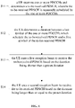
- FIG. 1 is a flow chart of a method for determining a PDSCH reception beam according to an embodiment. Referring to FIG. 1 , the method includes S11 to S14.
- a UE receives one or more PDCCHs and determines a to-be-received PDSCH, wherein the to-be-received PDSCH is repeatedly scheduled by the one or more PDCCHs.
- the UE determines a duration between a last symbol of the one or more PDCCHs which schedule the to-be-received PDSCH and a first symbol of the to-be-received PDSCH.
- the UE uses a first reception beam to receive the to-be-received PDSCH based on the duration being shorter than a preset duration.
- the UE uses a second reception beam to receive the to-be-received PDSCH based on the duration being longer than or equal to the preset duration.
- the first reception beam and the second reception beam are the same or different.
- the method may be implemented in a form of a software program which runs in a processor integrated inside a chip or a chip module.
- the UE receives one or more PDCCHs and determines the to-be-received PDSCH.
- PDSCH transmission follows PDCCH transmission.
- a way of PDCCH repeated transmission may be adopted.
- a TCI field carried in the by the one or more PDCCHs indicates transmission beam information of the PDSCH, and the terminal can obtain an appropriate reception beam based on the transmission beam information.
- processes such as reception and decoding of the PDCCHs take time, according to the NR standards, when a duration between the last symbol of the one or more PDCCHs and the first symbol of the PDSCH is shorter than a threshold, the base station uses a default beam to send the PDSCH, and the terminal uses the default beam to receive the PDSCH.
- the duration between the last symbol of the one or more PDCCHs which schedule the PDSCH and the first symbol of the PDSCH may be determined in different ways according to various ways of PDDCH repeated transmission.
- each of the one or more PDCCHs schedules a single PDSCH to send same downlink data, and different PDCCHs schedule different PDSCHs.
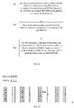
- FIG. 2 is a flow chart of S12 as shown in FIG. 1 according to an embodiment.
- Said determining the duration between the last symbol of the PDCCH scheduling the PDSCH and the first symbol of the PDSCH may include S21 to S22 which are described below.
- the UE determines the last symbol of the one or more PDCCHs based on the received one or more PDCCHs.
- the received PDCCH is the last PDCCH that schedules the PDSCH.
- the UE determines the duration between the last symbol of the PDCCH and the first symbol of the PDSCH based on the last symbol of the PDCCH and a time domain position of the to-be-received PDSCH.
- the time domain position of the to-be-received PDSCH may be determined in a conventional manner, which is not limited in the embodiments of the present disclosure.
- FIG. 3 is a diagram of the duration between the last symbol of the PDCCH and the first symbol of the PDSCH according to an embodiment.
- each PDCCH schedules a single PDSCH to transmit the same downlink data, for example, PDCCH (1) schedules PDSCH (1), PDCCH (2) schedules PDSCH (2), PDCCH (3) schedules PDSCH (3), and PDCCH (4) schedules PDSCH (4).
- an arrow as shown in FIG. 3 indicates the duration between the last symbol of PDCCH (3) and the first symbol of PDSCH (3).
- each of the one or more PDCCHs schedules a single PDSCH to send same downlink data, and different PDCCHs schedule different PDSCHs.
- the last symbol of the one or more PDCCHs is determined based on the one or more received PDCCHs, and the duration between the last symbol of the one or more PDCCHs and the first symbol of the to-be-received PDSCH is further determined, so as to realize solutions of the present disclosure in a case that each of the one or more PDCCHs schedules a single PDSCH to send same downlink data.
- each of the one or more PDCCHs schedules one or more PDSCHs to send same downlink data, and different PDCCHs schedule not exactly the same PDSCHs.
- N>1 PDCCHs are repeatedly transmitted to schedule M ⁇ 1 PDSCHs, where the M PDSCHs carry the same downlink data.
- Each PDCCH schedules K PDSCHs that have not been transmitted, and 1 ⁇ K ⁇ M.
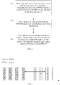
- FIG. 4 is a flow chart of S12 as shown in FIG. 1 according to an embodiment.
- Said determining the duration between the last symbol of the PDCCH scheduling the PDSCH and the first symbol of the PDSCH may include S41 to S43 which are described below.
- the UE determines a time domain position of a last PDCCH in the one or more PDCCHs for scheduling the to-be-received PDSCH based on the received one or more PDCCHs and high-layer configuration information.
- the high-layer configuration information may be acquired by the terminal through high-layer signaling, such as a Radio Resource Control (RRC) signaling, and may, for example, indicate which PDCCH is the last PDCCH.
- RRC Radio Resource Control
- the UE determines a last symbol of the last PDCCH based on the time domain position of the last PDCCH.
- the UE determines a duration between the last symbol of the last PDCCH and the first symbol of the to-be-received PDSCH based on the last symbol of the last PDCCH and the time domain position of the to-be-received PDSCH.
- FIG. 5 is a diagram of the duration between the last symbol of the PDCCH and the first symbol of the PDSCH according to an embodiment.
- each PDCCH schedules one or more PDSCHs to send the same downlink data, and the PDSCHs scheduled by different PDCCHs are not exactly the same.
- PDCCH (1) schedules PDSCH (1, 2, 3, 4)
- PDCCH (2) schedules PDSCH (2, 3, 4)
- PDCCH (3) schedules PDSCH (3, 4)
- PDCCH (4) schedules PDSCH (4).
- an arrow as shown in FIG. 5 indicates the duration between the last symbol of PDCCH (3) used to schedule PDSCH (3, 4) and the first symbol of PDSCH (3).
- each of the one or more PDCCHs schedules one or more PDSCHs to send same downlink data, and different PDCCHs schedule not exactly the same PDSCHs.
- the time domain position of the last PDCCH in the one or more PDCCHs for scheduling the to-be-received PDSCH is determined based on the received one or more PDCCHs and high-layer configuration information, the last symbol of the last PDCCH is determined, and the duration between the last symbol of the last PDCCH and the first symbol of the to-be-received PDSCH is further determined, so as to realize solutions of the present disclosure in a case that each of the one or more PDCCHs schedules a non-fixed number of PDSCHs.
- each of the one or more PDCCHs schedules one or more PDSCHs to send same downlink data, and different PDCCHs schedule the same PDSCHs.
- N>1 PDCCHs are repeatedly transmitted to schedule M ⁇ 1 PDSCHs, where the M PDSCHs carry the same downlink data.
- FIG. 6 is a flow chart of S12 as shown in FIG. 1 according to an embodiment.
- Said determining the duration between the last symbol of the PDCCH scheduling the PDSCH and the first symbol of the PDSCH may include S61 to S63 which are described below.
- the UE determines a time domain position of a last PDCCH in the one or more PDCCHs for scheduling the to-be-received PDSCH based on the received one or more PDCCHs and high-layer configuration information.
- the high-layer configuration information may be acquired by the terminal through high-layer signaling, such as an RRC signaling, and may, for example, indicate which PDCCH is the last PDCCH.
- high-layer signaling such as an RRC signaling
- the time domain position of the to-be-received PDSCH may be determined in a conventional manner, which is not limited in the embodiments of the present disclosure.
- the UE determines a last symbol of the last PDCCH based on the time domain position of the last PDCCH.
- the UE determines a duration between the last symbol of the last PDCCH and the first symbol of the to-be-received PDSCH based on the last symbol of the last PDCCH and the time domain position of the to-be-received PDSCH.
- FIG. 7 is a diagram of the duration between the last symbol of the PDCCH and the first symbol of the PDSCH according to an embodiment.
- each PDCCH schedules one or more PDSCHs to send the same downlink data, and the PDSCHs scheduled by different PDCCHs are the same.
- PDCCH (1) schedules PDSCH (1, 2, 3, 4)
- PDCCH (2) schedules PDSCH (1, 2, 3, 4)
- PDCCH (3) schedules PDSCH (1, 2, 3, 4)
- PDCCH (4) schedules PDSCH (1, 2, 3, 4).
- an arrow as shown in FIG. 7 indicates the duration between the last symbol of PDCCH (3) used to schedule PDSCH (1, 2, 3, 4) and the first symbol of PDSCH (3).
- each of the one or more PDCCHs schedules one or more PDSCHs to send same downlink data, and different PDCCHs schedule the same PDSCHs.
- the time domain position of the last PDCCH in the one or more PDCCHs for scheduling the to-be-received PDSCH is determined based on the received one or more PDCCHs and high-layer configuration information, the last symbol of the last PDCCH is determined, and the duration between the last symbol of the last PDCCH and the first symbol of the to-be-received PDSCH is further determined, so as to realize solutions of the present disclosure in a case that each of the one or more PDCCHs schedules a non-fixed number of PDSCHs.
- the UE may receive the PDSCH by using the first reception beam.
- the first reception beam may be predefined by a standard, such as a default beam.
- the first reception beam by setting the first reception beam to be predefined, accuracy and consistency of determining the same beam by a transmitter and a receiver may be improved, which is conducive to improving transceiving performance.
- the UE may receive the PDSCH by using the second reception beam.
- the first reception beam and the second reception beam are the same or different.
- scheduling information of the to-be-received PDSCH carried in the one or more PDCCHs that schedule the to-be-received PDSCH includes TCI indication information, is determined by decoding the one or more PDCCHs, and indicates the to-be-received PDSCH.
- Said using a second reception beam to receive the to-be-received PDSCH includes: using a reception beam corresponding to a transmission beam of the to-be-received PDSCH indicated by the TCI indication information as the second reception beam to receive the to-be-received PDSCH.
- said using a second reception beam to receive the to-be-received PDSCH includes: using a reception beam corresponding to a transmission beam of the to-be-received PDSCH indicated by the TCI indication information as the second reception beam to receive the to-be-received PDSCH.
- the preset duration is determined based on processing capability of the UE and reported to a base station.
- the preset duration is determined based on processing capability of the UE and reported by the UE to the base station, which may improve accuracy and adaptability of the determination of the preset duration, thereby further improving transceiving performance.
- the first reception beam or the second reception beam is used to receive the to-be-received PDSCH, which may enable the terminal to be capable of determining a transmission and reception beam adopted by each PDSCH, and improve consistency and accuracy in understanding of PDSCH transmission and reception beams by the base station and the terminal, thereby increasing a success rate of PDSCH reception.
- FIG. 8 is a structural diagram of an apparatus for determining a PDSCH reception beam according to an embodiment.
- the apparatus includes a PDSCH determining circuitry 81, a duration determining circuitry 82, a first beam determining circuitry 83 and a second beam determining circuitry 84.
- the PDSCH determining circuitry 81 is configured to receive one or more PDCCHs and determine a to-be-received PDSCH, wherein the to-be-received PDSCH is repeatedly scheduled by the one or more PDCCHs.
- the duration determining circuitry 82 is configured to determine a duration between a last symbol of the one or more PDCCHs which schedule the to-be-received PDSCH and a first symbol of the to-be-received PDSCH.
- the first beam determining circuitry 83 is configured to use a first reception beam to receive the to-be-received PDSCH based on the duration being shorter than a preset duration.
- the second beam determining circuitry 84 is configured to use a second reception beam to receive the to-be-received PDSCH based on the duration being longer than or equal to the preset duration.
- the first reception beam and the second reception beam are the same or different.
- the above apparatus may correspond to a chip with a data processing function in a UE, such as a baseband chip, or a chip module having a chip with a data processing function in a UE.
- the first reception beam or the second reception beam is used to receive the to-be-received PDSCH, which may enable the terminal to be capable of determining a transmission and reception beam adopted by each PDSCH, and improve consistency and accuracy in understanding of PDSCH transmission and reception beams by the base station and the terminal, thereby increasing a success rate of PDSCH reception.
- a storage medium having computer instructions stored therein wherein when the computer instructions are executed, the above method for determining a PDSCH reception beam is performed.
- the storage medium may be a computer readable storage medium, and may include a non-volatile or a non-transitory memory, or include an optical disk, a hard disk drive or a solid state disk.
- the processor may be a Central Processing Unit (CPU), or other general processors, Digital Signal Processors (DSPs), Application Specific Integrated Circuits (ASICs), Field Programmable Gate Arrays (FPGAs) or other Programmable logic devices, discrete gates or transistor logic devices, discrete hardware components, and the like.
- a general processor may be a microprocessor or the processor may be any conventional processor or the like.
- the memory in the embodiments of the present disclosure may be either volatile memory or nonvolatile memory, or may include both volatile and nonvolatile memories.
- the non-volatile memory may be a Read-Only Memory (ROM), a Programmable ROM (PROM), an Erasable PROM (EPROM), an electrically Erasable EPROM (EEPROM), or a flash memory.
- the volatile memory may be a Random Access Memory (RAM) which functions as an external cache.
- RAM Static Random Access Memory
- DRAM Dynamic Random Access Memory
- SDRAM Synchronous Dynamic Random Access Memory
- DDR SDRAM Double Data Rate Synchronous Dynamic Random Access Memory
- ESDRAM Enhanced SDRAM
- SLDRAM Synchronous connection to DRAM
- DR-RAM Direct Rambus RAM
- a terminal including a memory and a processor
- the memory has computer instructions stored therein, and when the processor executes the computer instructions, the above method for determining a PDSCH reception beam is performed.
- the terminal includes but is not limited to a mobile phone, a computer or a tablet computer.
- the terminal in the embodiments of the present disclosure may refer to various forms of UE, access terminal, user unit, user station, Mobile Station (MS), remote station, remote terminal, mobile equipment, user terminal, terminal equipment, wireless communication equipment, user agent or user device.
- the terminal equipment may further be a cellular phone, a cordless phone, a Session Initiation Protocol (SIP) phone, a Wireless Local Loop (WLL) station, a Personal Digital Assistant (PDA), a handheld device with a wireless communication function, a computing device or other processing devices connected to a wireless modems, an in-vehicle device, a wearable device, a terminal equipment in the future 5G network, or a terminal equipment in a future evolved Public Land Mobile Network (PLMN), which is not limited in the embodiments of the present disclosure.
- SIP Session Initiation Protocol
- WLL Wireless Local Loop
- PDA Personal Digital Assistant
- Modules/units included in each apparatus and product described in the above embodiments may be software modules/units, hardware modules/units, or a combination of software modules/units and hardware modules/units.
- each module/unit included therein may be implemented by hardware such as circuits; or, at least some modules/units may be implemented by a software program running on a processor integrated inside the chip, and the remaining (if any) part of the modules/units may be implemented by hardware such as circuits.
- each module/unit included therein may be implemented by hardware such as circuits.
- Different modules/units may be disposed in a same component (such as a chip or a circuit module) or in different components of the chip module. Or at least some modules/units may be implemented by a software program running on a processor integrated inside the chip module, and the remaining (if any) part of the modules/units may be implemented by hardware such as circuits. For each apparatus or product applied to or integrated in a terminal, each module/unit included therein may be implemented by hardware such as circuits. Different modules/units may be disposed in a same component (such as a chip or a circuit module) or in different components of the terminal. Or at least some modules/units may be implemented by a software program running on a processor integrated inside the terminal, and the remaining (if any) part of the modules/units may be implemented by hardware such as circuits.
Landscapes
- Engineering & Computer Science (AREA)
- Signal Processing (AREA)
- Computer Networks & Wireless Communication (AREA)
- Mobile Radio Communication Systems (AREA)
Abstract
Description
- This application claims priority to
Chinese Patent Application No. 202010074010.5, filed on January 22, 2020 - The present disclosure generally relates to communication technology field, and more particularly, to a method and apparatus for determining a Physical Downlink Share Channel (PDSCH) reception beam, a storage medium, and a terminal.
- In high frequency band scenarios, according to New Radio (NR) standards, a base station and a terminal determine an optimal transmission and reception beam through a beam training process, so as to use the optimal transceiver beam to improve transmission reliability of uplink and downlink signals. During the beam training process, the terminal saves a reception beam corresponding to each reported transmission beam. In a process of scheduling a PDSCH by a Physical Downlink Control Channel (PDCCH), a TCI field carried in the PDCCH indicates transmission beam information of the PDSCH. The terminal obtains an appropriate reception beam based on the transmission beam information.
- At present, the standards merely support that each PDCCH independently schedules different PDSCHs to send downlink data, but do not support multiple PDCCHs to schedule a same PDSCH. To improve transmission reliability of PDCCH, in a researching stage of the 3GPP new radio release 16 (Rel-16), a method of using PDCCH repeated transmission to improve reliability of PDCCH is discussed. However, in the end, PDCCH repeated transmission is not standardized, and there is no method for determining a transmission and reception beam adopted by each PDSCH.
- A method for determining a PDSCH transmission and reception beam is needed, which can enable the terminal to determine a transmission and reception beam adopted by each PDSCH when the PDSCH is scheduled in a manner of PDCCH repeated transmission, and improve consistency and accuracy of transmission and reception beams determined by the base station and the terminal.
- In embodiments of the present disclosure, a method and apparatus for determining a PDSCH reception beam, a storage medium, and a terminal are provided, which may enable the terminal to be capable of determining a transmission and reception beam adopted by each PDSCH, and improve consistency and accuracy in understanding of PDSCH transmission and reception beams by a base station and the terminal, thereby increasing a success rate of PDSCH reception.
- In an embodiment of the present disclosure, a method for determining a PDSCH reception beam is provided, including: receiving one or more PDCCHs and determining a to-be-received PDSCH, wherein the to-be-received PDSCH is repeatedly scheduled by the one or more PDCCHs; determining a duration between a last symbol of the one or more PDCCHs which schedule the to-be-received PDSCH and a first symbol of the to-be-received PDSCH; using a first reception beam to receive the to-be-received PDSCH based on the duration being shorter than a preset duration; and using a second reception beam to receive the to-be-received PDSCH based on the duration being longer than or equal to the preset duration, wherein the first reception beam and the second reception beam are the same or different.
- Optionally, each of the one or more PDCCHs schedules a single PDSCH to send same downlink data, and different PDCCHs schedule different PDSCHs; and said determining a duration between a last symbol of the one or more PDCCHs which schedule the to-be-received PDSCH and a first symbol of the to-be-received PDSCH includes: determining the last symbol of the one or more PDCCHs; and determining the duration between the last symbol of the one or more PDCCHs and the first symbol of the to-be-received PDSCH based on the last symbol of the one or more PDCCHs and a time domain position of the to-be-received PDSCH.
- Optionally, each of the one or more PDCCHs schedules one or more PDSCHs to send same downlink data, and different PDCCHs schedule not exactly the same PDSCHs; and said determining a duration between a last symbol of the one or more PDCCHs which schedule the to-be-received PDSCH and a first symbol of the to-be-received PDSCH includes: determining a time domain position of a last PDCCH in the one or more PDCCHs for scheduling the to-be-received PDSCH based on the received one or more PDCCHs and high-layer configuration information; determining a last symbol of the last PDCCH based on the time domain position of the last PDCCH; and determining a duration between the last symbol of the last PDCCH and the first symbol of the to-be-received PDSCH based on the last symbol of the last PDCCH and the time domain position of the to-be-received PDSCH.
- Optionally, each of the one or more PDCCHs schedules one or more PDSCHs to send same downlink data, and different PDCCHs schedule same PDSCHs; and said determining a duration between a last symbol of the one or more PDCCHs which schedule the to-be-received PDSCH and a first symbol of the to-be-received PDSCH includes: determining a time domain position of a last PDCCH in the one or more PDCCHs for scheduling the to-be-received PDSCH based on the received one or more PDCCHs and high-layer configuration information; determining a last symbol of the last PDCCH based on the time domain position of the last PDCCH; and determining a duration between the last symbol of the last PDCCH and the first symbol of the to-be-received PDSCH based on the last symbol of the last PDCCH and the time domain position of the to-be-received PDSCH.
- Optionally, the first reception beam is predefined.
- Optionally, the preset duration is determined based on processing capability of a terminal and reported to a base station.
- Optionally, scheduling information of the to-be-received PDSCH carried in the one or more PDCCHs that schedule the to-be-received PDSCH includes TCI indication information, is determined by decoding the one or more PDCCHs, and indicates the to-be-received PDSCH; said using a second reception beam to receive the to-be-received PDSCH includes: using a reception beam corresponding to a transmission beam of the to-be-received PDSCH indicated by the TCI indication information as the second reception beam to receive the to-be-received PDSCH.
- In an embodiment of the present disclosure, an apparatus for determining a PDSCH reception beam is provided, including: a PDSCH determining circuitry configured to receive one or more PDCCHs and determine a to-be-received PDSCH, wherein the to-be-received PDSCH is repeatedly scheduled by the one or more PDCCHs; a duration determining circuitry configured to determine a duration between a last symbol of the one or more PDCCHs which schedule the to-be-received PDSCH and a first symbol of the to-be-received PDSCH; a first beam determining circuitry configured to use a first reception beam to receive the to-be-received PDSCH based on the duration being shorter than a preset duration; and a second beam determining circuitry configured to use a second reception beam to receive the to-be-received PDSCH based on the duration being longer than or equal to the preset duration, wherein the first reception beam and the second reception beam are the same or different.
- In an embodiment of the present disclosure, a storage medium having computer instructions stored therein is provided, wherein when the computer instructions are executed, the above method for determining the PDSCH reception beam is performed.
- In an embodiment of the present disclosure, a terminal including a memory and a processor is provided, wherein the memory has computer instructions stored therein, and when the processor executes the computer instructions, the above method for determining the PDSCH reception beam is performed.
- Embodiments of the present disclosure may provide following advantages.
- In embodiments of the present disclosure, one or more PDCCHs are received and a to-be-received PDSCH is determined, wherein the to-be-received PDSCH is repeatedly scheduled by the one or more PDCCHs. A duration between a last symbol of the one or more PDCCHs which schedule the to-be-received PDSCH and a first symbol of the to-be-received PDSCH is determined. A first reception beam is used to receive the to-be-received PDSCH based on the duration being shorter than a preset duration, and a second reception beam is used to receive the to-be-received PDSCH based on the duration being longer than or equal to the preset duration, wherein the first reception beam and the second reception beam are the same or different. With the above solutions, to the to-be-received PDSCH repeatedly scheduled by the one or more PDCCHs, by determining the duration between the last symbol of the one or more PDCCHs which schedule the to-be-received PDSCH and the first symbol of the to-be-received PDSCH, and comparing the duration with the preset duration, the first reception beam or the second reception beam is used to receive the to-be-received PDSCH, which may enable the terminal to be capable of determining a transmission and reception beam adopted by each PDSCH, and improve consistency and accuracy in understanding of PDSCH transmission and reception beams by the base station and the terminal, thereby increasing a success rate of PDSCH reception.
- Further, in embodiments of the present disclosure, each of the one or more PDCCHs schedules a single PDSCH to send same downlink data, and different PDCCHs schedule different PDSCHs. In this case, the last symbol of the one or more PDCCHs is determined based on the one or more received PDCCHs, and the duration between the last symbol of the one or more PDCCHs and the first symbol of the to-be-received PDSCH is further determined, so as to realize solutions of the present disclosure in a case that each of the one or more PDCCHs schedules a single PDSCH to send same downlink data.
- Further, in embodiments of the present disclosure, each of the one or more PDCCHs schedules one or more PDSCHs to send same downlink data, and different PDCCHs schedule not exactly the same PDSCHs. In this case, the time domain position of the last PDCCH in the one or more PDCCHs for scheduling the to-be-received PDSCH is determined based on the received one or more PDCCHs and high-layer configuration information, the last symbol of the last PDCCH is determined, and the duration between the last symbol of the last PDCCH and the first symbol of the to-be-received PDSCH is further determined, so as to realize solutions of the present disclosure in a case that each of the one or more PDCCHs schedules a non-fixed number of PDSCHs.
- Further, in embodiments of the present disclosure, each of the one or more PDCCHs schedules one or more PDSCHs to send same downlink data, and different PDCCHs schedule same PDSCHs. In this case, the time domain position of the last PDCCH in the one or more PDCCHs for scheduling the to-be-received PDSCH is determined based on the received one or more PDCCHs and high-layer configuration information, the last symbol of the last PDCCH is determined, and the duration between the last symbol of the last PDCCH and the first symbol of the to-be-received PDSCH is further determined, so as to realize solutions of the present disclosure in a case that each of the one or more PDCCHs schedules a fixed number of PDSCHs.
- Further, in embodiments of the present disclosure, said using a second reception beam to receive the to-be-received PDSCH includes: using a reception beam corresponding to a transmission beam of the to-be-received PDSCH indicated by the TCI indication information as the second reception beam to receive the to-be-received PDSCH. In this manner, when the duration between the last symbol of the last PDCCH and the first symbol of the to-be-received PDSCH is relatively long, there is an opportunity to use the second reception beam. Besides, the terminal is capable of keeping consistent with the base station, and accuracy of beam determination is improved.
-
-
FIG. 1 is a flow chart of a method for determining a PDSCH reception beam according to an embodiment; -
FIG. 2 is a flow chart of S12 as shown inFIG. 1 according to an embodiment; -
FIG. 3 is a diagram of a duration between a last symbol of a PDCCH and a first symbol of a PDSCH according to an embodiment; -
FIG. 4 is a flow chart of S12 as shown inFIG. 1 according to an embodiment; -
FIG. 5 is a diagram of a duration between a last symbol of a PDCCH and a first symbol of a PDSCH according to an embodiment; -
FIG. 6 is a flow chart of S12 as shown inFIG. 1 according to an embodiment; -
FIG. 7 is a diagram of a duration between a last symbol of a PDCCH and a first symbol of a PDSCH according to an embodiment; and -
FIG. 8 is a structural diagram of an apparatus for determining a PDSCH reception beam according to an embodiment. - As described in the background, at present, the standards merely support that each PDCCH independently schedules different PDSCHs to send downlink data, but do not support multiple PDCCHs to schedule a same PDSCH. To improve transmission reliability of PDCCH, in a researching stage of the 3GPP Rel-16, a method of using PDCCH repeated transmission to improve reliability of PDCCH is discussed.
- Specifically, in a discussion process of the NR Rel-16, there are following three ways of scheduling PDSCH by repeated transmission of PDCCH. It is assumed that N>1 PDCCHs are repeatedly sent to schedule M≥1 PDSCHs, where the M PDSCHs carry same downlink data.
- Way 1: each PDCCH schedules a PDSCH different from others, and M=N.
- Way 2: each PDCCH schedules K untransmitted PDSCHs, and 1≤K≤M.
- Way 3: each PDCCH schedules M same PDSCHs, that is, K=M.
- However, inventors found based on researches that in the NR Rel-16, PDCCH repeated transmission is not standardized, and there is no method for determining a transmission and reception beam adopted by each PDSCH. Therefore, the terminal cannot determine a transmission and reception beam adopted by each PDSCH when the PDSCH is scheduled in a manner of PDCCH repeated transmission, and consistency and accuracy of transmission and reception beams determined by the base station and the terminal are relatively low.
- In embodiments of the present disclosure, one or more PDCCHs are received and a to-be-received PDSCH is determined, wherein the to-be-received PDSCH is repeatedly scheduled by the one or more PDCCHs. A duration between a last symbol of the one or more PDCCHs which schedule the to-be-received PDSCH and a first symbol of the to-be-received PDSCH is determined. A first reception beam is used to receive the to-be-received PDSCH based on the duration being shorter than a preset duration, and a second reception beam is used to receive the to-be-received PDSCH based on the duration being longer than or equal to the preset duration, wherein the first reception beam and the second reception beam are the same or different. With the above solutions, to the to-be-received PDSCH repeatedly scheduled by the one or more PDCCHs, by determining the duration between the last symbol of the one or more PDCCHs which schedule the to-be-received PDSCH and the first symbol of the to-be-received PDSCH, and comparing the duration with the preset duration, the first reception beam or the second reception beam is used to receive the to-be-received PDSCH, which may enable the terminal to be capable of determining a transmission and reception beam adopted by each PDSCH, and improve consistency and accuracy in understanding of PDSCH transmission and reception beams by the base station and the terminal, thereby increasing a success rate of PDSCH reception.
- In order to clarify the objects, characteristics and advantages of the disclosure, embodiments of present disclosure will be described in detail in conjunction with accompanying drawings.
-
FIG. 1 is a flow chart of a method for determining a PDSCH reception beam according to an embodiment. Referring toFIG. 1 , the method includes S11 to S14. - In S11, a UE receives one or more PDCCHs and determines a to-be-received PDSCH, wherein the to-be-received PDSCH is repeatedly scheduled by the one or more PDCCHs.
- In S12, the UE determines a duration between a last symbol of the one or more PDCCHs which schedule the to-be-received PDSCH and a first symbol of the to-be-received PDSCH.
- In S13, the UE uses a first reception beam to receive the to-be-received PDSCH based on the duration being shorter than a preset duration.
- In S14, the UE uses a second reception beam to receive the to-be-received PDSCH based on the duration being longer than or equal to the preset duration.
- The first reception beam and the second reception beam are the same or different.
- It could be understood that, in some embodiments, the method may be implemented in a form of a software program which runs in a processor integrated inside a chip or a chip module.
- In some embodiments, in S11, the UE receives one or more PDCCHs and determines the to-be-received PDSCH.
- Specifically, in a process of scheduling the PDSCH by the one or more PDCCHs, PDSCH transmission follows PDCCH transmission. As mentioned above, to improve reliability of PDCCH transmission, a way of PDCCH repeated transmission may be adopted.
- In some embodiments, in the process of scheduling PDSCH by the one or more PDCCHs, a TCI field carried in the by the one or more PDCCHs indicates transmission beam information of the PDSCH, and the terminal can obtain an appropriate reception beam based on the transmission beam information. As processes such as reception and decoding of the PDCCHs take time, according to the NR standards, when a duration between the last symbol of the one or more PDCCHs and the first symbol of the PDSCH is shorter than a threshold, the base station uses a default beam to send the PDSCH, and the terminal uses the default beam to receive the PDSCH.
- In some embodiments, in S12, the duration between the last symbol of the one or more PDCCHs which schedule the PDSCH and the first symbol of the PDSCH may be determined in different ways according to various ways of PDDCH repeated transmission.
- In some embodiments, each of the one or more PDCCHs schedules a single PDSCH to send same downlink data, and different PDCCHs schedule different PDSCHs.
- Specifically, it is assumed that N>1 PDCCHs are repeatedly transmitted to schedule M≥1 PDSCHs, where the M PDSCHs carry the same downlink data. That is, each PDCCH schedules a PDSCH different from others, and M=N.
- Referring to
FIG. 2, FIG. 2 is a flow chart of S12 as shown inFIG. 1 according to an embodiment. Said determining the duration between the last symbol of the PDCCH scheduling the PDSCH and the first symbol of the PDSCH may include S21 to S22 which are described below. - In S21, the UE determines the last symbol of the one or more PDCCHs based on the received one or more PDCCHs.
- In some embodiments, as each PDCCH schedules a single PDSCH to send the same downlink data, the received PDCCH is the last PDCCH that schedules the PDSCH.
- In S22, the UE determines the duration between the last symbol of the PDCCH and the first symbol of the PDSCH based on the last symbol of the PDCCH and a time domain position of the to-be-received PDSCH.
- In some embodiments, the time domain position of the to-be-received PDSCH may be determined in a conventional manner, which is not limited in the embodiments of the present disclosure.
- Referring to
FIG. 3, FIG. 3 is a diagram of the duration between the last symbol of the PDCCH and the first symbol of the PDSCH according to an embodiment. - As shown in
FIG. 3 , each PDCCH schedules a single PDSCH to transmit the same downlink data, for example, PDCCH (1) schedules PDSCH (1), PDCCH (2) schedules PDSCH (2), PDCCH (3) schedules PDSCH (3), and PDCCH (4) schedules PDSCH (4). - Taking PDSCH (3) as an example, an arrow as shown in
FIG. 3 indicates the duration between the last symbol of PDCCH (3) and the first symbol of PDSCH (3). - In the above embodiments, each of the one or more PDCCHs schedules a single PDSCH to send same downlink data, and different PDCCHs schedule different PDSCHs. In this case, the last symbol of the one or more PDCCHs is determined based on the one or more received PDCCHs, and the duration between the last symbol of the one or more PDCCHs and the first symbol of the to-be-received PDSCH is further determined, so as to realize solutions of the present disclosure in a case that each of the one or more PDCCHs schedules a single PDSCH to send same downlink data.
- In some embodiments, each of the one or more PDCCHs schedules one or more PDSCHs to send same downlink data, and different PDCCHs schedule not exactly the same PDSCHs.
- Specifically, it is assumed that N>1 PDCCHs are repeatedly transmitted to schedule M≧1 PDSCHs, where the M PDSCHs carry the same downlink data. Each PDCCH schedules K PDSCHs that have not been transmitted, and 1≦K≦M.
- Referring to
FIG. 4, FIG. 4 is a flow chart of S12 as shown inFIG. 1 according to an embodiment. Said determining the duration between the last symbol of the PDCCH scheduling the PDSCH and the first symbol of the PDSCH may include S41 to S43 which are described below. - In S41, the UE determines a time domain position of a last PDCCH in the one or more PDCCHs for scheduling the to-be-received PDSCH based on the received one or more PDCCHs and high-layer configuration information.
- In some embodiments, the high-layer configuration information may be acquired by the terminal through high-layer signaling, such as a Radio Resource Control (RRC) signaling, and may, for example, indicate which PDCCH is the last PDCCH.
- In some embodiments, the time domain position of the to-be-received PDSCH may be determined in a conventional manner, which is not limited in the embodiments of the present disclosure.
- In S42, the UE determines a last symbol of the last PDCCH based on the time domain position of the last PDCCH.
- In S43, the UE determines a duration between the last symbol of the last PDCCH and the first symbol of the to-be-received PDSCH based on the last symbol of the last PDCCH and the time domain position of the to-be-received PDSCH.
- Referring to
FIG. 5, FIG. 5 is a diagram of the duration between the last symbol of the PDCCH and the first symbol of the PDSCH according to an embodiment. - As shown in
FIG. 5 , each PDCCH schedules one or more PDSCHs to send the same downlink data, and the PDSCHs scheduled by different PDCCHs are not exactly the same. For example, PDCCH (1) schedules PDSCH (1, 2, 3, 4), PDCCH (2) schedules PDSCH (2, 3, 4), PDCCH (3) schedules PDSCH (3, 4), and PDCCH (4) schedules PDSCH (4). - Taking PDSCH (3) as an example, an arrow as shown in
FIG. 5 indicates the duration between the last symbol of PDCCH (3) used to schedule PDSCH (3, 4) and the first symbol of PDSCH (3). - In the above embodiments, each of the one or more PDCCHs schedules one or more PDSCHs to send same downlink data, and different PDCCHs schedule not exactly the same PDSCHs. In this case, the time domain position of the last PDCCH in the one or more PDCCHs for scheduling the to-be-received PDSCH is determined based on the received one or more PDCCHs and high-layer configuration information, the last symbol of the last PDCCH is determined, and the duration between the last symbol of the last PDCCH and the first symbol of the to-be-received PDSCH is further determined, so as to realize solutions of the present disclosure in a case that each of the one or more PDCCHs schedules a non-fixed number of PDSCHs.
- In some embodiments, each of the one or more PDCCHs schedules one or more PDSCHs to send same downlink data, and different PDCCHs schedule the same PDSCHs.
- Specifically, it is assumed that N>1 PDCCHs are repeatedly transmitted to schedule M≧1 PDSCHs, where the M PDSCHs carry the same downlink data. Each PDCCH schedules M same PDSCHs, i.e., K=M.
- Referring to
FIG. 6, FIG. 6 is a flow chart of S12 as shown inFIG. 1 according to an embodiment. Said determining the duration between the last symbol of the PDCCH scheduling the PDSCH and the first symbol of the PDSCH may include S61 to S63 which are described below. - In S61, the UE determines a time domain position of a last PDCCH in the one or more PDCCHs for scheduling the to-be-received PDSCH based on the received one or more PDCCHs and high-layer configuration information.
- In some embodiments, the high-layer configuration information may be acquired by the terminal through high-layer signaling, such as an RRC signaling, and may, for example, indicate which PDCCH is the last PDCCH.
- In some embodiments, the time domain position of the to-be-received PDSCH may be determined in a conventional manner, which is not limited in the embodiments of the present disclosure.
- In S62, the UE determines a last symbol of the last PDCCH based on the time domain position of the last PDCCH.
- In S63, the UE determines a duration between the last symbol of the last PDCCH and the first symbol of the to-be-received PDSCH based on the last symbol of the last PDCCH and the time domain position of the to-be-received PDSCH.
- Referring to
FIG. 7, FIG. 7 is a diagram of the duration between the last symbol of the PDCCH and the first symbol of the PDSCH according to an embodiment. - As shown in
FIG. 7 , each PDCCH schedules one or more PDSCHs to send the same downlink data, and the PDSCHs scheduled by different PDCCHs are the same. For example, PDCCH (1) schedules PDSCH (1, 2, 3, 4), PDCCH (2) schedules PDSCH (1, 2, 3, 4), PDCCH (3) schedules PDSCH (1, 2, 3, 4), and PDCCH (4) schedules PDSCH (1, 2, 3, 4). - Taking PDSCH (3) as an example, an arrow as shown in
FIG. 7 indicates the duration between the last symbol of PDCCH (3) used to schedule PDSCH (1, 2, 3, 4) and the first symbol of PDSCH (3). - In the above embodiments, each of the one or more PDCCHs schedules one or more PDSCHs to send same downlink data, and different PDCCHs schedule the same PDSCHs. In this case, the time domain position of the last PDCCH in the one or more PDCCHs for scheduling the to-be-received PDSCH is determined based on the received one or more PDCCHs and high-layer configuration information, the last symbol of the last PDCCH is determined, and the duration between the last symbol of the last PDCCH and the first symbol of the to-be-received PDSCH is further determined, so as to realize solutions of the present disclosure in a case that each of the one or more PDCCHs schedules a non-fixed number of PDSCHs.
- Still referring to
FIG. 1 , in some embodiments, in S13, based on the duration being shorter than the preset duration, the UE may receive the PDSCH by using the first reception beam. - Further, the first reception beam may be predefined.
- Specifically, the first reception beam may be predefined by a standard, such as a default beam.
- In the embodiments, by setting the first reception beam to be predefined, accuracy and consistency of determining the same beam by a transmitter and a receiver may be improved, which is conducive to improving transceiving performance.
- In some embodiments, in S14, if the duration being longer than or equal to the preset duration, the UE may receive the PDSCH by using the second reception beam.
- The first reception beam and the second reception beam are the same or different.
- Further, scheduling information of the to-be-received PDSCH carried in the one or more PDCCHs that schedule the to-be-received PDSCH includes TCI indication information, is determined by decoding the one or more PDCCHs, and indicates the to-be-received PDSCH. Said using a second reception beam to receive the to-be-received PDSCH includes: using a reception beam corresponding to a transmission beam of the to-be-received PDSCH indicated by the TCI indication information as the second reception beam to receive the to-be-received PDSCH.
- In the above embodiments, said using a second reception beam to receive the to-be-received PDSCH includes: using a reception beam corresponding to a transmission beam of the to-be-received PDSCH indicated by the TCI indication information as the second reception beam to receive the to-be-received PDSCH. In this manner, when the duration between the last symbol of the last PDCCH and the first symbol of the to-be-received PDSCH is relatively long, there is an opportunity to use the second reception beam. Besides, the terminal is capable of keeping consistent with the base station, and accuracy of beam determination is improved.
- Further, the preset duration is determined based on processing capability of the UE and reported to a base station.
- In the above embodiments, the preset duration is determined based on processing capability of the UE and reported by the UE to the base station, which may improve accuracy and adaptability of the determination of the preset duration, thereby further improving transceiving performance.
- In the embodiments of the present disclosure, to the to-be-received PDSCH repeatedly scheduled by the one or more PDCCHs, by determining the duration between the last symbol of the one or more PDCCHs which schedule the to-be-received PDSCH and the first symbol of the to-be-received PDSCH, and comparing the duration with the preset duration, the first reception beam or the second reception beam is used to receive the to-be-received PDSCH, which may enable the terminal to be capable of determining a transmission and reception beam adopted by each PDSCH, and improve consistency and accuracy in understanding of PDSCH transmission and reception beams by the base station and the terminal, thereby increasing a success rate of PDSCH reception.
- Referring to
FIG. 8, FIG. 8 is a structural diagram of an apparatus for determining a PDSCH reception beam according to an embodiment. The apparatus includes aPDSCH determining circuitry 81, aduration determining circuitry 82, a firstbeam determining circuitry 83 and a secondbeam determining circuitry 84. - The
PDSCH determining circuitry 81 is configured to receive one or more PDCCHs and determine a to-be-received PDSCH, wherein the to-be-received PDSCH is repeatedly scheduled by the one or more PDCCHs. - The
duration determining circuitry 82 is configured to determine a duration between a last symbol of the one or more PDCCHs which schedule the to-be-received PDSCH and a first symbol of the to-be-received PDSCH. - The first
beam determining circuitry 83 is configured to use a first reception beam to receive the to-be-received PDSCH based on the duration being shorter than a preset duration. - The second
beam determining circuitry 84 is configured to use a second reception beam to receive the to-be-received PDSCH based on the duration being longer than or equal to the preset duration. - The first reception beam and the second reception beam are the same or different.
- In some embodiments, the above apparatus may correspond to a chip with a data processing function in a UE, such as a baseband chip, or a chip module having a chip with a data processing function in a UE.
- In the embodiments of the present disclosure, to the to-be-received PDSCH repeatedly scheduled by the one or more PDCCHs, by determining the duration between the last symbol of the one or more PDCCHs which schedule the to-be-received PDSCH and the first symbol of the to-be-received PDSCH, and comparing the duration with the preset duration, the first reception beam or the second reception beam is used to receive the to-be-received PDSCH, which may enable the terminal to be capable of determining a transmission and reception beam adopted by each PDSCH, and improve consistency and accuracy in understanding of PDSCH transmission and reception beams by the base station and the terminal, thereby increasing a success rate of PDSCH reception.
- More details on principles, implementations and advantages of the apparatus may be referred to relevant descriptions of the method as mentioned above and illustrated in
FIGS. 1 to 7 , which are not repeated here. - In an embodiment of the present disclosure, a storage medium having computer instructions stored therein is provided, wherein when the computer instructions are executed, the above method for determining a PDSCH reception beam is performed. In some embodiments, the storage medium may be a computer readable storage medium, and may include a non-volatile or a non-transitory memory, or include an optical disk, a hard disk drive or a solid state disk.
- In the embodiments of the present disclosure, the processor may be a Central Processing Unit (CPU), or other general processors, Digital Signal Processors (DSPs), Application Specific Integrated Circuits (ASICs), Field Programmable Gate Arrays (FPGAs) or other Programmable logic devices, discrete gates or transistor logic devices, discrete hardware components, and the like. A general processor may be a microprocessor or the processor may be any conventional processor or the like.
- It should also be understood that the memory in the embodiments of the present disclosure may be either volatile memory or nonvolatile memory, or may include both volatile and nonvolatile memories. The non-volatile memory may be a Read-Only Memory (ROM), a Programmable ROM (PROM), an Erasable PROM (EPROM), an electrically Erasable EPROM (EEPROM), or a flash memory. The volatile memory may be a Random Access Memory (RAM) which functions as an external cache. By way of example but not limitation, various forms of RAM are available, such as Static Random Access Memory (SRAM), Dynamic Random Access Memory (DRAM), Synchronous Dynamic Random Access Memory (SDRAM), Double Data Rate Synchronous Dynamic Random Access Memory (DDR SDRAM), Enhanced SDRAM (ESDRAM), Synchronous connection to DRAM (SLDRAM), and Direct Rambus RAM (DR-RAM).
- In an embodiment of the present disclosure, a terminal including a memory and a processor is provided, wherein the memory has computer instructions stored therein, and when the processor executes the computer instructions, the above method for determining a PDSCH reception beam is performed. The terminal includes but is not limited to a mobile phone, a computer or a tablet computer.
- The terminal in the embodiments of the present disclosure may refer to various forms of UE, access terminal, user unit, user station, Mobile Station (MS), remote station, remote terminal, mobile equipment, user terminal, terminal equipment, wireless communication equipment, user agent or user device. The terminal equipment may further be a cellular phone, a cordless phone, a Session Initiation Protocol (SIP) phone, a Wireless Local Loop (WLL) station, a Personal Digital Assistant (PDA), a handheld device with a wireless communication function, a computing device or other processing devices connected to a wireless modems, an in-vehicle device, a wearable device, a terminal equipment in the future 5G network, or a terminal equipment in a future evolved Public Land Mobile Network (PLMN), which is not limited in the embodiments of the present disclosure.
- Modules/units included in each apparatus and product described in the above embodiments may be software modules/units, hardware modules/units, or a combination of software modules/units and hardware modules/units. For example, for each apparatus or product applied to or integrated in a chip, each module/unit included therein may be implemented by hardware such as circuits; or, at least some modules/units may be implemented by a software program running on a processor integrated inside the chip, and the remaining (if any) part of the modules/units may be implemented by hardware such as circuits. For each apparatus or product applied to or integrated in a chip module, each module/unit included therein may be implemented by hardware such as circuits. Different modules/units may be disposed in a same component (such as a chip or a circuit module) or in different components of the chip module. Or at least some modules/units may be implemented by a software program running on a processor integrated inside the chip module, and the remaining (if any) part of the modules/units may be implemented by hardware such as circuits. For each apparatus or product applied to or integrated in a terminal, each module/unit included therein may be implemented by hardware such as circuits. Different modules/units may be disposed in a same component (such as a chip or a circuit module) or in different components of the terminal. Or at least some modules/units may be implemented by a software program running on a processor integrated inside the terminal, and the remaining (if any) part of the modules/units may be implemented by hardware such as circuits.
- Although the present disclosure has been disclosed above with reference to preferred embodiments thereof, it should be understood that the disclosure is presented by way of example only, and not limitation. Those skilled in the art can modify and vary the embodiments without departing from the spirit and scope of the present disclosure.
Claims (10)
- A method for determining a Physical Downlink Share Channel (PDSCH) reception beam, characterized by comprising:receiving one or more Physical Downlink Control Channels (PDCCHs) and determining a to-be-received PDSCH, wherein the to-be-received PDSCH is repeatedly scheduled by the one or more PDCCHs;determining a duration between a last symbol of the one or more PDCCHs which schedule the to-be-received PDSCH and a first symbol of the to-be-received PDSCH;using a first reception beam to receive the to-be-received PDSCH based on the duration being shorter than a preset duration; andusing a second reception beam to receive the to-be-received PDSCH based on the duration being longer than or equal to the preset duration,wherein the first reception beam and the second reception beam are the same or different.
- The method according to claim 1, characterized in that each of the one or more PDCCHs schedules a single PDSCH to send same downlink data, and different PDCCHs schedule different PDSCHs; and said determining a duration between a last symbol of the one or more PDCCHs which schedule the to-be-received PDSCH and a first symbol of the to-be-received PDSCH comprises:determining the last symbol of the one or more PDCCHs; anddetermining the duration between the last symbol of the one or more PDCCHs and the first symbol of the to-be-received PDSCH based on the last symbol of the one or more PDCCHs and a time domain position of the to-be-received PDSCH.
- The method according to claim 1, characterized in that each of the one or more PDCCHs schedules one or more PDSCHs to send same downlink data, and different PDCCHs schedule not exactly the same PDSCHs; and said determining a duration between a last symbol of the one or more PDCCHs which schedule the to-be-received PDSCH and a first symbol of the to-be-received PDSCH comprises:determining a time domain position of a last PDCCH in the one or more PDCCHs for scheduling the to-be-received PDSCH based on the received one or more PDCCHs and high-layer configuration information;determining a last symbol of the last PDCCH based on the time domain position of the last PDCCH; anddetermining a duration between the last symbol of the last PDCCH and the first symbol of the to-be-received PDSCH based on the last symbol of the last PDCCH and the time domain position of the to-be-received PDSCH.
- The method according to claim 1, characterized in that each of the one or more PDCCHs schedules one or more PDSCHs to send same downlink data, and different PDCCHs schedule same PDSCHs; and said determining a duration between a last symbol of the one or more PDCCHs which schedule the to-be-received PDSCH and a first symbol of the to-be-received PDSCH comprises:determining a time domain position of a last PDCCH in the one or more PDCCHs for scheduling the to-be-received PDSCH based on the received one or more PDCCHs and high-layer configuration information;determining a last symbol of the last PDCCH based on the time domain position of the last PDCCH; anddetermining a duration between the last symbol of the last PDCCH and the first symbol of the to-be-received PDSCH based on the last symbol of the last PDCCH and the time domain position of the to-be-received PDSCH.
- The method according to claim 1, characterized in that the first reception beam is predefined.
- The method according to claim 1, characterized in that the preset duration is determined based on processing capability of a terminal and reported to a base station.
- The method according to claim 1, characterized in that scheduling information of the to-be-received PDSCH carried in the one or more PDCCHs that schedule the to-be-received PDSCH comprises TCI indication information, is determined by decoding the one or more PDCCHs, and indicates the to-be-received PDSCH;
said using a second reception beam to receive the to-be-received PDSCH comprises:
using a reception beam corresponding to a transmission beam of the to-be-received PDSCH indicated by the TCI indication information as the second reception beam to receive the to-be-received PDSCH. - An apparatus for determining a Physical Downlink Share Channel (PDSCH) reception beam, characterized by comprising:a PDSCH determining circuitry configured to receive one or more Physical Downlink Control Channels (PDCCHs) and determine a to-be-received PDSCH, wherein the to-be-received PDSCH is repeatedly scheduled by the one or more PDCCHs;a duration determining circuitry configured to determine a duration between a last symbol of the one or more PDCCHs which schedule the to-be-received PDSCH and a first symbol of the to-be-received PDSCH;a first beam determining circuitry configured to use a first reception beam to receive the to-be-received PDSCH based on the duration being shorter than a preset duration; anda second beam determining circuitry configured to use a second reception beam to receive the to-be-received PDSCH based on the duration being longer than or equal to the preset duration,wherein the first reception beam and the second reception beam are the same or different.
- A storage medium having computer instructions stored therein, characterized in that when the computer instructions are executed, the method of any one of claims 1 to 7 is performed.
- A terminal comprising a memory and a processor, characterized in that the memory has computer instructions stored therein, and when the processor executes the computer instructions, the method of any one of claims 1 to 7 is performed.
Applications Claiming Priority (2)
| Application Number | Priority Date | Filing Date | Title |
|---|---|---|---|
| CN202010074010.5A CN111212437B (en) | 2020-01-22 | 2020-01-22 | Method and device for determining PDSCH (physical Downlink shared channel) receiving beam, storage medium and terminal |
| PCT/CN2021/081719 WO2021148056A2 (en) | 2020-01-22 | 2021-03-19 | Method and apparatus for determining pdsch reception beam, storage medium, and terminal |
Publications (2)
| Publication Number | Publication Date |
|---|---|
| EP4096275A2 true EP4096275A2 (en) | 2022-11-30 |
| EP4096275A4 EP4096275A4 (en) | 2023-11-08 |
Family
ID=70788493
Family Applications (1)
| Application Number | Title | Priority Date | Filing Date |
|---|---|---|---|
| EP21744032.0A Pending EP4096275A4 (en) | 2020-01-22 | 2021-03-19 | Method and apparatus for determining pdsch reception beam, storage medium, and terminal |
Country Status (4)
| Country | Link |
|---|---|
| US (1) | US20230140021A1 (en) |
| EP (1) | EP4096275A4 (en) |
| CN (1) | CN111212437B (en) |
| WO (1) | WO2021148056A2 (en) |
Families Citing this family (4)
| Publication number | Priority date | Publication date | Assignee | Title |
|---|---|---|---|---|
| CN111212437B (en) * | 2020-01-22 | 2022-07-19 | 北京紫光展锐通信技术有限公司 | Method and device for determining PDSCH (physical Downlink shared channel) receiving beam, storage medium and terminal |
| CN115136693A (en) * | 2020-04-21 | 2022-09-30 | Oppo广东移动通信有限公司 | Information transmission method, terminal equipment and storage medium |
| CN113784439B (en) * | 2020-06-09 | 2024-06-25 | 大唐移动通信设备有限公司 | Control information transmission method, terminal and network equipment |
| EP3961960B1 (en) | 2020-08-28 | 2022-11-30 | ASUSTek Computer Inc. | Reception of pdsch scheduled by first pdcch and by second pdcch using a qcl assumption |
Family Cites Families (9)
| Publication number | Priority date | Publication date | Assignee | Title |
|---|---|---|---|---|
| TW201728207A (en) * | 2015-11-10 | 2017-08-01 | Idac控股公司 | Downlink control channel design and signaling for beamformed systems |
| CN111543097B (en) * | 2017-11-15 | 2023-12-26 | 交互数字专利控股公司 | Beam management in a wireless network |
| CN109818723B (en) * | 2017-11-21 | 2020-12-29 | 中国移动通信有限公司研究院 | Method for data transmission, network side equipment and terminal |
| US11212057B2 (en) * | 2018-06-15 | 2021-12-28 | Acer Incorporated | Device and method for handling physical downlink shared channels in bandwidth parts |
| CN115002911A (en) * | 2018-06-15 | 2022-09-02 | 成都华为技术有限公司 | Repeat transmission method and communication device |
| CN110719631B (en) * | 2018-07-12 | 2021-12-28 | 维沃移动通信有限公司 | Method for determining scheduling parameters, method for configuring scheduling parameters, terminal and network side equipment |
| CN113541908B (en) * | 2018-09-27 | 2023-06-06 | 中兴通讯股份有限公司 | Data transmission method and device, and data receiving method and device |
| CN110351775B (en) * | 2019-08-02 | 2022-04-12 | 北京云智软通信息技术有限公司 | Method and system for processing beam indication in 5G communication |
| CN111212437B (en) * | 2020-01-22 | 2022-07-19 | 北京紫光展锐通信技术有限公司 | Method and device for determining PDSCH (physical Downlink shared channel) receiving beam, storage medium and terminal |
-
2020
- 2020-01-22 CN CN202010074010.5A patent/CN111212437B/en active Active
-
2021
- 2021-03-19 WO PCT/CN2021/081719 patent/WO2021148056A2/en unknown
- 2021-03-19 EP EP21744032.0A patent/EP4096275A4/en active Pending
- 2021-03-19 US US17/794,523 patent/US20230140021A1/en active Pending
Also Published As
| Publication number | Publication date |
|---|---|
| WO2021148056A3 (en) | 2021-09-16 |
| CN111212437A (en) | 2020-05-29 |
| CN111212437B (en) | 2022-07-19 |
| EP4096275A4 (en) | 2023-11-08 |
| US20230140021A1 (en) | 2023-05-04 |
| WO2021148056A2 (en) | 2021-07-29 |
Similar Documents
| Publication | Publication Date | Title |
|---|---|---|
| EP4096275A2 (en) | Method and apparatus for determining pdsch reception beam, storage medium, and terminal | |
| EP4221033A1 (en) | Resource indication method and apparatus for prs under sidelink communication, and storage medium and terminal | |
| EP3565150B1 (en) | Uplink transmission method, terminal, and network device | |
| US11950265B2 (en) | Data transmission method, terminal device, and network device | |
| US11394504B2 (en) | Method and apparatus for uplink transmission | |
| US20200145973A1 (en) | Information transmission method, apparatus and terminal | |
| US20220124793A1 (en) | Wireless communication method, terminal device, and network device | |
| US11991729B2 (en) | Resource configuration method and apparatus, and communication device | |
| US11800508B2 (en) | Method and device for transmitting and receiving uplink data | |
| US20210160857A1 (en) | Information transmission method, terminal device and network device | |
| US11425663B2 (en) | Wireless communication method, terminal device, and network device | |
| US11956793B2 (en) | Information processing method, device and storage medium | |
| CN111757524A (en) | Method for determining uplink control information and communication equipment | |
| US20200128516A1 (en) | Wireless Communication Method, Terminal Device, and Network Device | |
| US11985672B2 (en) | Data transmission method and apparatus, network device and terminal | |
| WO2019157734A1 (en) | Method, apparatus and system for determining maximum transmit power, and storage medium | |
| WO2021196975A1 (en) | Information receiving and sending method and apparatus, storage medium, and terminal | |
| EP3758406A1 (en) | Method and apparatus for determining trigger state, terminal, and network device | |
| WO2020024250A1 (en) | Wireless communication method, terminal device, and network device | |
| US20220386353A1 (en) | Channel processing method and electronic device | |
| WO2022022190A1 (en) | Method for sounding reference signal resrouce transmission and terminal devices | |
| CN114727392A (en) | Identification method and device of public beam, storage medium, terminal and network terminal | |
| CN115804221A (en) | Wireless communication method and apparatus |
Legal Events
| Date | Code | Title | Description |
|---|---|---|---|
| STAA | Information on the status of an ep patent application or granted ep patent |
Free format text: STATUS: THE INTERNATIONAL PUBLICATION HAS BEEN MADE |
|
| PUAI | Public reference made under article 153(3) epc to a published international application that has entered the european phase |
Free format text: ORIGINAL CODE: 0009012 |
|
| STAA | Information on the status of an ep patent application or granted ep patent |
Free format text: STATUS: REQUEST FOR EXAMINATION WAS MADE |
|
| 17P | Request for examination filed |
Effective date: 20220822 |
|
| AK | Designated contracting states |
Kind code of ref document: A2 Designated state(s): AL AT BE BG CH CY CZ DE DK EE ES FI FR GB GR HR HU IE IS IT LI LT LU LV MC MK MT NL NO PL PT RO RS SE SI SK SM TR |
|
| XX | Miscellaneous (additional remarks) |
Free format text: THE FILING DATE OF THE INTERNATIONAL APPLICATION IS WITHIN TWO MONTHS FROM THE DATE OF EXPIRATION OF THE PRIORITY PERIOD (R. 26BIS.3 PCT). |
|
| XX | Miscellaneous (additional remarks) |
Free format text: A REQUEST FOR RESTORATION OF THE RIGHT OF PRIORITY UNDER RULE 49TER.2 PCT IS PENDING BEFORE THE EPO AS DESIGNATED OFFICE. |
|
| DAV | Request for validation of the european patent (deleted) | ||
| DAX | Request for extension of the european patent (deleted) | ||
| A4 | Supplementary search report drawn up and despatched |
Effective date: 20231009 |
|
| RIC1 | Information provided on ipc code assigned before grant |
Ipc: H04B 7/00 20060101ALI20231002BHEP Ipc: H04L 5/00 20060101ALI20231002BHEP Ipc: H04W 72/04 20090101ALI20231002BHEP Ipc: H04W 24/02 20090101AFI20231002BHEP |