EP4096122A1 - Validating synchronized local times of at least a first and a second control unit - Google Patents
Validating synchronized local times of at least a first and a second control unit Download PDFInfo
- Publication number
- EP4096122A1 EP4096122A1 EP21176508.6A EP21176508A EP4096122A1 EP 4096122 A1 EP4096122 A1 EP 4096122A1 EP 21176508 A EP21176508 A EP 21176508A EP 4096122 A1 EP4096122 A1 EP 4096122A1
- Authority
- EP
- European Patent Office
- Prior art keywords
- control unit
- local time
- time
- synchronized
- synchronization message
- Prior art date
- Legal status (The legal status is an assumption and is not a legal conclusion. Google has not performed a legal analysis and makes no representation as to the accuracy of the status listed.)
- Pending
Links
Images
Classifications
-
- H—ELECTRICITY
- H04—ELECTRIC COMMUNICATION TECHNIQUE
- H04J—MULTIPLEX COMMUNICATION
- H04J3/00—Time-division multiplex systems
- H04J3/02—Details
- H04J3/14—Monitoring arrangements
-
- H—ELECTRICITY
- H04—ELECTRIC COMMUNICATION TECHNIQUE
- H04J—MULTIPLEX COMMUNICATION
- H04J3/00—Time-division multiplex systems
- H04J3/02—Details
- H04J3/06—Synchronising arrangements
- H04J3/0635—Clock or time synchronisation in a network
- H04J3/0638—Clock or time synchronisation among nodes; Internode synchronisation
- H04J3/0658—Clock or time synchronisation among packet nodes
- H04J3/0661—Clock or time synchronisation among packet nodes using timestamps
- H04J3/0664—Clock or time synchronisation among packet nodes using timestamps unidirectional timestamps
-
- H—ELECTRICITY
- H04—ELECTRIC COMMUNICATION TECHNIQUE
- H04J—MULTIPLEX COMMUNICATION
- H04J3/00—Time-division multiplex systems
- H04J3/02—Details
- H04J3/06—Synchronising arrangements
- H04J3/0635—Clock or time synchronisation in a network
- H04J3/0638—Clock or time synchronisation among nodes; Internode synchronisation
- H04J3/0658—Clock or time synchronisation among packet nodes
- H04J3/0661—Clock or time synchronisation among packet nodes using timestamps
- H04J3/0667—Bidirectional timestamps, e.g. NTP or PTP for compensation of clock drift and for compensation of propagation delays
Definitions
- the present invention is directed to a method for validating synchronized local times of at least a first and a second control unit of a vehicle, and a communication network configured to carry out the method.
- the background of the invention is with respect to automated vehicles with functions corresponding to level 1 and/or level 2 according to SAE J3016, but is not limited thereto.
- an automated or autonomous vehicle e.g. a car
- the data processing may be done on one control unit (ECU), e.g., included in one of the sensors, thereby taking the data from the sensors as an input, fusing the data and processing the data before sending data, e.g., a control signal, to the vehicle.
- ECU control unit
- the data of the multiple sensors need to have the same, i.e., a synchronized, timestamp.
- level 2 vehicles some functions, such as automatic emergency braking, may require sensor fusion with ASIL B (Automotive Safety Integrity Level, safety requirement level specified by ISO 26262 for safety-relevant systems in motor vehicles) from input sensors such as a camera, a radar sensor and/or a lidar sensor.
- ASIL B Automotive Safety Integrity Level, safety requirement level specified by ISO 26262 for safety-relevant systems in motor vehicles
- One of the given sensors may act as a master and the other sensors may act as a slave providing the required data with ASIL integrity to the master.
- the input sensors including master and slave are not synchronized with respect to one global time, it may result into safety goal violation and hence non-fulfillment of the required ASIL integrity.
- An object of the invention is to provide a solution to ensure that at least some, preferably all, sensors of a network uses a synchronized timestamp. More concretely, one object of the invention may be formulated as to provide a solution suitable to ensure a time synchronization for sensor fusion of data provided by multiple perception sensors used at a level 2 vehicle.
- the object is solved by a method for validating synchronized local times of at least a first and a second control unit of a vehicle.
- the method comprises a step of receiving, at each one of the at least two control units, a first synchronization message including a master time.
- the method further comprises a step of synchronizing, at each one of the at least two control units, a local time of the respective one of the at least two control units to the received master time.
- the method further comprises a step of communicating the synchronized local time from the first control unit to the second control unit.
- the method further comprises a step of comparing, at the second control unit, the communicated local time of the first control unit to the synchronized local time of the second control unit for validating the synchronized local times of the at least two control units.
- the step of comparing the communicated local time of the first control unit to the synchronized local time of the second control unit may include determining, at the second control unit, a difference between the communicated local time of the first control unit and the synchronized local time of the second control unit, and raising, at the second control unit, an error flag if the determined difference is larger than a predefined threshold.
- the step of communicating the synchronized local time from the first control unit to the second control unit may include sending a second synchronization message from the first control unit to the second control unit.
- the second synchronization message may include a first local time corresponding to the synchronized local time of the first control unit at the time of sending the second synchronization message.
- the step of communicating the synchronized local time from the first control unit to the second control unit may include sending a follow-up message from the first control unit to the second control unit when a predetermined time after sending the second synchronization message is expired.
- the follow-up message may include the first local time corresponding to the synchronized local time of the first control unit at the time of sending the second synchronization message.
- the step of comparing the communicated local time of the first control unit to the synchronized local time of the second control unit may include determining, at the second control unit, the communicated local time based on the second synchronization message and/or the follow-up message.
- the step of determining the communicated local time may include determining, at the second control unit, a first local time corresponding to the synchronized local time of the second control unit at the time of receiving the second synchronization message.
- the step of determining the communicated local time may further include determining, at the second control unit, a second local time corresponding to the synchronized local time of the second control unit at the time of receiving the follow-up message.
- the step of determining the communicated local time may further include determining, at the second control unit, a difference between the first local time corresponding to the synchronized local time of the first control unit at the time of sending the second synchronization message and the first local time corresponding to the synchronized local time of the second control unit at the time of receiving the second synchronization message.
- the step of determining the communicated local time may further include determining, at the second control unit, a sum of the difference and the second local time corresponding to the synchronized local time of the second control unit at the time of receiving the follow-up message for determining the communicated local time.
- Each one of multiple sensors inputting their data to a common sensor data fusion receives a synchronization message from a grand master.
- the master sensor carrying out the sensor data fusion also receives the synchronization message from the grand master and synchronizes itself with respect to a grand master time included in the synchronization message.
- All slave sensors irrespective of their communication standard (e.g., Flexray, CAN-FD or Ethernet), carry out a forward synchronization with respect to the time grand master and a backward synchronization method with respect to the master sensor.
- their communication standard e.g., Flexray, CAN-FD or Ethernet
- the master sensor receives a backward time synchronization message from each slave sensor indicating the time with which the respective slave sensor is synchronized.
- the master sensor verifies each received time synchronization message received from the slave sensors by cross checking it with the time synchronization message provided by the other slave sensors and also with its own synchronized local time.
- a synchronization error is detected and a corresponding error message, e.g., indicating 'time sync. failed', is set by the master sensor.
- the safety integrity level of the master sensor may also be claimed by the slave sensors. That is, if the master sensor is implemented as ASIL D, then the slave sensors could also claim ASIL D.
- the forward and/or backward synchronization may use the synchronized time-base manager (StbM) and the time synchronization communication stack with respect to each communication bus.
- StbM synchronized time-base manager
- the backward synchronization message may have a different EtherType than that of the forward Synchronization message.
- the forward and/or backward time synchronization may be done using the Precision Time Protocol (PTP) including four or five messages (i.e., synchronization message, (synchronization) follow-up message, delay request message, delay response message, and delay response follow-up message) at least partly.
- PTP Precision Time Protocol
- the backward synchronization message could be reduced to only two messages from the PTP communication protocol, i.e., the synchronization and the follow-up message, thereby reducing the CPU utilization.
- the backward synchronization could also be provided with five messages of communication protocol for sensors.
- a communication network comprising a first and a second control unit being connected to each other is provided.
- the first and/or the second control unit may be part of a sensor, such as a camera, a radar sensor and/or a lidar sensor.
- the first control unit may be called slave control unit.
- the second control unit may be called master control unit.
- the second control unit may be configured to carry out data processing, e.g., a sensor data fusion, with data provided by the first and/or the second control unit.
- the first and/or the second control unit may comprise a local clock providing the local time, respectively.
- the first and the second control unit are configured to receive a synchronization message including a master time, respectively.
- the communication network may further comprise a master time control unit, wherein the master time control unit may be configured to send the master time to the first and the second control unit, optionally cyclically or periodically.
- the master time control unit may comprise a hardware counter for providing the master time.
- Automotive Safety Integrity Level is a risk classification scheme defined by the ISO 26262 - Functional Safety for Road Vehicles standard. This classification helps defining the safety requirements necessary to be in line with the ISO 26262 standard.
- the ASIL is established by performing a risk analysis of a potential hazard by looking at the Severity, Exposure and Controllability of the vehicle operating scenario. The safety goal for that hazard in turn carries the ASIL requirements.
- ASIL D dictates the highest integrity requirements on the product and ASIL A the lowest. Hazards that are identified as QM do not dictate any safety requirements.
- the master time may also be provided with ASIL, e.g., with ASIL B.
- the first and the second control unit are configured to synchronize their local time to the received master time, respectively.
- the first control unit is configured to communicate the synchronized local time to the second control unit.
- the first control unit may be configured to communicate its synchronized local time with ASIL, e.g., ASIL B.
- ASIL e.g., ASIL B.
- the second control unit is configured to compare the communicated local time of the first control unit to the synchronized local time of the second control unit for validating the synchronized local times of the first and the second control unit.
- the second control unit may be configured to validate the synchronized local times with ASIL, e.g., ASIL B.
- ASIL e.g., ASIL B.
- the communication network may be configured to carry out the above describe method at least partly.
- the description given above with respect to the method applies mutatis mutandis to the communication network and vice versa.
- the second control unit may be configured to determine a difference between the communicated local time of the first control unit and the synchronized local time of the second control unit, and raise an error flag if the determined difference is larger than a predefined threshold.
- the first control unit may be configured to send a second synchronization message to the second control unit.
- the second synchronization message may include a first local time corresponding to the synchronized local time of the first control unit at the time of sending the synchronization message.
- the first control unit may be configured to send a follow-up message to the second control unit when a predetermined time after sending the second synchronization message is expired.
- the follow-up message may include the first local time corresponding to the synchronized local time of the first control unit at the time of sending the second synchronization message.
- the second control unit may be configured to determine the communicated local time based on the second synchronization message and/or the follow-up message.
- the second control unit may be configured to determine a first local time corresponding to the synchronized local time of the second control unit at the time of receiving the second synchronization message.
- the second control unit may be further configured to determine a second local time corresponding to the synchronized local time of the second control unit at the time of receiving the follow-up message.
- the second control unit may be further configured to determine a difference between the first local time corresponding to the synchronized local time of the first control unit at the time of sending the second synchronization message and the first local time corresponding to the synchronized local time of the second control unit at the time of receiving the second synchronization message.
- the second control unit may be further configured to determine a sum of the difference and the second local time corresponding to the synchronized local time of the second control unit at the time of receiving the follow-up message for determining the communicated local time.
- the communication network 1 comprises a master control unit 3 and a slave control unit 4, and is connected to a master time control unit 2.
- the communication network 1 is configured to carry out the method for validating the synchronized local times of the master and the slave unit 3, 4.
- the master time control unit 2 sends a first synchronization message including a master time to the master control unit 3 and the slave control unit 4, respectively, such that both control units 3, 4 receive the first synchronization message including the master time.
- a second step S2 of the method the master and the slave control unit 3, 4 synchronize their local time to the received master time, respectively.
- the first and the second step S1, S2 may be called forward synchronization, wherein the PTP may be used for the forward synchronization.
- a third step S3 of the method the slave control unit 4 communicates its synchronized local time to the master control unit 3.
- a fourth step S4 of the method the master control unit 4 compares the communicated local time of the slave control unit 4 to the synchronized local time of the master control unit 3 for validating the synchronized local times of the two control units 3, 4.
- the master control unit 3 determines a difference between the communicated local time of the slave control unit 4 and the synchronized local time of the master control unit 3, and raises an error flag if the determined difference is larger than a predefined threshold.
- the slave control unit 4 sends a second synchronization message to the master control unit 3 in the third step S3, wherein the second synchronization message includes the local time corresponding to the synchronized local time of the slave control unit 3 at the time of sending the second synchronization message.
- the master control unit 3 determines the communicated local time based on the second synchronization message sent in the third step S3, e.g., the communicated local time is the local time included in the second synchronization message, and compares the determined communicated local time to the synchronized local time of the master control unit 4.
- the slave control unit 4 sends a second synchronization message to the master control unit 3 in the third step S3, wherein the second synchronization message does not necessarily include the local time corresponding to the synchronized local time of the slave control unit 3 at the time of sending the second synchronization message.
- the slave control unit 4 When a predetermined time after sending the second synchronization message is expired, the slave control unit 4 sends a follow-up message to the master control unit 3, wherein the follow-up message includes the local time corresponding to the synchronized local time of the first control unit at the time of sending the second synchronization message.
- the master control unit 3 determines the communicated local time based on the second synchronization message and the follow-up message of the third step S3, and compares the determined communicated local time to the synchronized local time of the master control unit 4.
- step S3, S4 may be carried out at least partly simultaneously.
- the master control unit 3 determines in the fourth step S4 a local time corresponding to, e.g., being, the synchronized local time of the master control unit 3 at the time of receiving the second synchronization message in the third step S3.
- the master control unit 3 determines in the fourth step S4 a local time corresponding to, e.g., being, the synchronized local time of the master control unit 3 at the time of receiving the follow-up message in the third step S3.
- the master control unit 3 determines a difference between the local time corresponding to the synchronized local time of the slave control unit 4 at the time of sending the second synchronization message, i.e., the time included in the follow-up message send in the third step S3, and the determined local time corresponding to the synchronized local time of the master control unit 3 at the time of receiving the second synchronization message in the third step S3.
- the master control unit 3 determines a sum of the determined difference and the local time corresponding to the synchronized local time of the master control unit 3 at the time of receiving the follow-up message. That is, the determined difference is added to the determined local time corresponding to the synchronized local time of the master control unit 3 at the time of receiving the follow-up message.
- the determined i.e., calculated sum, is in the present case equal to the communicated local time.
- the first two messages of the PTP are used for the backward synchronization.
- the invention is not limited thereto and it would also be possible to use all four messages, or even five messages, of the PTP by additionally providing a follow-up message following a delay response for carrying out the backward synchronization.
- the invention is not limited to two control units. It is also possible to provide more than two control units, e.g., one master control unit for several slave control units, and to carry out the above described method for every slave control unit, respectively, and/or do a cross checking of the synchronized local times of the slave control units using the above described method at a respective master control unit.
Abstract
Description
- The present invention is directed to a method for validating synchronized local times of at least a first and a second control unit of a vehicle, and a communication network configured to carry out the method.
- The background of the invention is with respect to automated vehicles with functions corresponding to level 1 and/or
level 2 according to SAE J3016, but is not limited thereto. - In general, for an automated or autonomous vehicle, e.g. a car, there is a lot of data processing including perception from multiple sensors. The data processing may be done on one control unit (ECU), e.g., included in one of the sensors, thereby taking the data from the sensors as an input, fusing the data and processing the data before sending data, e.g., a control signal, to the vehicle. Especially for fusing the data, the data of the multiple sensors need to have the same, i.e., a synchronized, timestamp.
- More specifically, for
level 2 vehicles some functions, such as automatic emergency braking, may require sensor fusion with ASIL B (Automotive Safety Integrity Level, safety requirement level specified by ISO 26262 for safety-relevant systems in motor vehicles) from input sensors such as a camera, a radar sensor and/or a lidar sensor. - One of the given sensors may act as a master and the other sensors may act as a slave providing the required data with ASIL integrity to the master.
- If the input sensors including master and slave are not synchronized with respect to one global time, it may result into safety goal violation and hence non-fulfillment of the required ASIL integrity.
- An object of the invention is to provide a solution to ensure that at least some, preferably all, sensors of a network uses a synchronized timestamp. More concretely, one object of the invention may be formulated as to provide a solution suitable to ensure a time synchronization for sensor fusion of data provided by multiple perception sensors used at a
level 2 vehicle. - This object is solved by the features of the independent claims. The dependent claims contain preferred further developments of the invention.
- More specifically, the object is solved by a method for validating synchronized local times of at least a first and a second control unit of a vehicle.
- The method comprises a step of receiving, at each one of the at least two control units, a first synchronization message including a master time.
- The method further comprises a step of synchronizing, at each one of the at least two control units, a local time of the respective one of the at least two control units to the received master time.
- The method further comprises a step of communicating the synchronized local time from the first control unit to the second control unit.
- The method further comprises a step of comparing, at the second control unit, the communicated local time of the first control unit to the synchronized local time of the second control unit for validating the synchronized local times of the at least two control units.
- The step of comparing the communicated local time of the first control unit to the synchronized local time of the second control unit may include determining, at the second control unit, a difference between the communicated local time of the first control unit and the synchronized local time of the second control unit, and raising, at the second control unit, an error flag if the determined difference is larger than a predefined threshold.
- The step of communicating the synchronized local time from the first control unit to the second control unit may include sending a second synchronization message from the first control unit to the second control unit. The second synchronization message may include a first local time corresponding to the synchronized local time of the first control unit at the time of sending the second synchronization message.
- The step of communicating the synchronized local time from the first control unit to the second control unit may include sending a follow-up message from the first control unit to the second control unit when a predetermined time after sending the second synchronization message is expired. The follow-up message may include the first local time corresponding to the synchronized local time of the first control unit at the time of sending the second synchronization message.
- The step of comparing the communicated local time of the first control unit to the synchronized local time of the second control unit may include determining, at the second control unit, the communicated local time based on the second synchronization message and/or the follow-up message.
- The step of determining the communicated local time may include determining, at the second control unit, a first local time corresponding to the synchronized local time of the second control unit at the time of receiving the second synchronization message.
- The step of determining the communicated local time may further include determining, at the second control unit, a second local time corresponding to the synchronized local time of the second control unit at the time of receiving the follow-up message.
- The step of determining the communicated local time may further include determining, at the second control unit, a difference between the first local time corresponding to the synchronized local time of the first control unit at the time of sending the second synchronization message and the first local time corresponding to the synchronized local time of the second control unit at the time of receiving the second synchronization message.
- The step of determining the communicated local time may further include determining, at the second control unit, a sum of the difference and the second local time corresponding to the synchronized local time of the second control unit at the time of receiving the follow-up message for determining the communicated local time.
- In the following, the above given abstract description is summarized in other words and concretized.
- Each one of multiple sensors inputting their data to a common sensor data fusion receives a synchronization message from a grand master.
- The master sensor carrying out the sensor data fusion also receives the synchronization message from the grand master and synchronizes itself with respect to a grand master time included in the synchronization message.
- For a successful sensor data fusion with ASIL integrity, all sensors need to be synchronized to the grand master time.
- All slave sensors, irrespective of their communication standard (e.g., Flexray, CAN-FD or Ethernet), carry out a forward synchronization with respect to the time grand master and a backward synchronization method with respect to the master sensor.
- The master sensor receives a backward time synchronization message from each slave sensor indicating the time with which the respective slave sensor is synchronized.
- The master sensor verifies each received time synchronization message received from the slave sensors by cross checking it with the time synchronization message provided by the other slave sensors and also with its own synchronized local time.
- If there is any deviation larger than a given threshold, a synchronization error is detected and a corresponding error message, e.g., indicating 'time sync. failed', is set by the master sensor.
- Thus, the safety integrity level of the master sensor may also be claimed by the slave sensors. That is, if the master sensor is implemented as ASIL D, then the slave sensors could also claim ASIL D.
- In case of using the AUTOSAR standard, the forward and/or backward synchronization may use the synchronized time-base manager (StbM) and the time synchronization communication stack with respect to each communication bus.
- In case of using the Ethernet standard, the backward synchronization message may have a different EtherType than that of the forward Synchronization message.
- The forward and/or backward time synchronization may be done using the Precision Time Protocol (PTP) including four or five messages (i.e., synchronization message, (synchronization) follow-up message, delay request message, delay response message, and delay response follow-up message) at least partly.
- That is, e.g., at an Ethernet communication bus, the backward synchronization message could be reduced to only two messages from the PTP communication protocol, i.e., the synchronization and the follow-up message, thereby reducing the CPU utilization. In order to improve accuracy, the backward synchronization could also be provided with five messages of communication protocol for sensors.
- Furthermore, a communication network comprising a first and a second control unit being connected to each other is provided.
- The first and/or the second control unit may be part of a sensor, such as a camera, a radar sensor and/or a lidar sensor. The first control unit may be called slave control unit. The second control unit may be called master control unit. The second control unit may be configured to carry out data processing, e.g., a sensor data fusion, with data provided by the first and/or the second control unit. The first and/or the second control unit may comprise a local clock providing the local time, respectively.
- The first and the second control unit are configured to receive a synchronization message including a master time, respectively.
- The communication network may further comprise a master time control unit, wherein the master time control unit may be configured to send the master time to the first and the second control unit, optionally cyclically or periodically. The master time control unit may comprise a hardware counter for providing the master time.
- With respect to a safety integrity level: Automotive Safety Integrity Level (ASIL), as used herein, is a risk classification scheme defined by the ISO 26262 - Functional Safety for Road Vehicles standard. This classification helps defining the safety requirements necessary to be in line with the ISO 26262 standard. The ASIL is established by performing a risk analysis of a potential hazard by looking at the Severity, Exposure and Controllability of the vehicle operating scenario. The safety goal for that hazard in turn carries the ASIL requirements. There are four ASILs identified by the standard: ASIL A, ASIL B, ASIL C, ASIL D. ASIL D dictates the highest integrity requirements on the product and ASIL A the lowest. Hazards that are identified as QM do not dictate any safety requirements.
- It may be sufficient, if the master time is provided with QM. However, the master time may also be provided with ASIL, e.g., with ASIL B.
- The first and the second control unit are configured to synchronize their local time to the received master time, respectively.
- The first control unit is configured to communicate the synchronized local time to the second control unit.
- The first control unit may be configured to communicate its synchronized local time with ASIL, e.g., ASIL B.
- The second control unit is configured to compare the communicated local time of the first control unit to the synchronized local time of the second control unit for validating the synchronized local times of the first and the second control unit.
- The second control unit may be configured to validate the synchronized local times with ASIL, e.g., ASIL B.
- The communication network may be configured to carry out the above describe method at least partly. The description given above with respect to the method applies mutatis mutandis to the communication network and vice versa.
- For comparing the communicated local time of the first control unit to the synchronized local time of the second control unit, the second control unit may be configured to determine a difference between the communicated local time of the first control unit and the synchronized local time of the second control unit, and raise an error flag if the determined difference is larger than a predefined threshold.
- For communicating the synchronized local time from the first control unit to the second control unit, the first control unit may be configured to send a second synchronization message to the second control unit. The second synchronization message may include a first local time corresponding to the synchronized local time of the first control unit at the time of sending the synchronization message.
- For communicating the synchronized local time from the first control unit to the second control unit, the first control unit may be configured to send a follow-up message to the second control unit when a predetermined time after sending the second synchronization message is expired. The follow-up message may include the first local time corresponding to the synchronized local time of the first control unit at the time of sending the second synchronization message.
- For comparing the communicated local time of the first control unit to the synchronized local time of the second control unit, the second control unit may be configured to determine the communicated local time based on the second synchronization message and/or the follow-up message.
- For determining the communicated local time, the second control unit may be configured to determine a first local time corresponding to the synchronized local time of the second control unit at the time of receiving the second synchronization message.
- For determining the communicated local time, the second control unit may be further configured to determine a second local time corresponding to the synchronized local time of the second control unit at the time of receiving the follow-up message.
- For determining the communicated local time, the second control unit may be further configured to determine a difference between the first local time corresponding to the synchronized local time of the first control unit at the time of sending the second synchronization message and the first local time corresponding to the synchronized local time of the second control unit at the time of receiving the second synchronization message.
- For determining the communicated local time, the second control unit may be further configured to determine a sum of the difference and the second local time corresponding to the synchronized local time of the second control unit at the time of receiving the follow-up message for determining the communicated local time.
- In the following, a description of an embodiment of the present invention is given with respect to
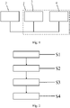
figures 1 and 2 . - Fig. 1
- depicts schematically a communication network of a vehicle configured to carry out a method for validating synchronized local times.
- Fig. 2
- depicts schematically a flowchart of the method for validating the synchronized local times.
- As can be gathered from
figure 1 , the communication network 1 comprises amaster control unit 3 and aslave control unit 4, and is connected to a mastertime control unit 2. - The communication network 1 is configured to carry out the method for validating the synchronized local times of the master and the
slave unit - In a first step S1 of the method, the master
time control unit 2 sends a first synchronization message including a master time to themaster control unit 3 and theslave control unit 4, respectively, such that bothcontrol units - In a second step S2 of the method, the master and the
slave control unit - The first and the second step S1, S2 may be called forward synchronization, wherein the PTP may be used for the forward synchronization.
- In a third step S3 of the method, the
slave control unit 4 communicates its synchronized local time to themaster control unit 3. - In a fourth step S4 of the method, the
master control unit 4 compares the communicated local time of theslave control unit 4 to the synchronized local time of themaster control unit 3 for validating the synchronized local times of the twocontrol units - Therefore, the
master control unit 3 determines a difference between the communicated local time of theslave control unit 4 and the synchronized local time of themaster control unit 3, and raises an error flag if the determined difference is larger than a predefined threshold. - For communicating the synchronized local time from the
slave control unit 4 to themaster control unit 3 in the third step S3 and for comparing the communicated local time of theslave control unit 4 to the synchronized local time of themaster control unit 3 in the fourth step S4, i.e., for the backward synchronization, two options are possible which may be carried out additionally or alternatively. - In a first option, the
slave control unit 4 sends a second synchronization message to themaster control unit 3 in the third step S3, wherein the second synchronization message includes the local time corresponding to the synchronized local time of theslave control unit 3 at the time of sending the second synchronization message. - In the fourth step S4, the
master control unit 3 determines the communicated local time based on the second synchronization message sent in the third step S3, e.g., the communicated local time is the local time included in the second synchronization message, and compares the determined communicated local time to the synchronized local time of themaster control unit 4. - In a second option, the
slave control unit 4 sends a second synchronization message to themaster control unit 3 in the third step S3, wherein the second synchronization message does not necessarily include the local time corresponding to the synchronized local time of theslave control unit 3 at the time of sending the second synchronization message. - When a predetermined time after sending the second synchronization message is expired, the
slave control unit 4 sends a follow-up message to themaster control unit 3, wherein the follow-up message includes the local time corresponding to the synchronized local time of the first control unit at the time of sending the second synchronization message. - In the fourth step S4, the
master control unit 3 determines the communicated local time based on the second synchronization message and the follow-up message of the third step S3, and compares the determined communicated local time to the synchronized local time of themaster control unit 4. - Determining the communicated local time according to the second option will be explained in detail below, wherein the third and the fourth step S3, S4 may be carried out at least partly simultaneously.
- The
master control unit 3 determines in the fourth step S4 a local time corresponding to, e.g., being, the synchronized local time of themaster control unit 3 at the time of receiving the second synchronization message in the third step S3. - Furthermore, the
master control unit 3 determines in the fourth step S4 a local time corresponding to, e.g., being, the synchronized local time of themaster control unit 3 at the time of receiving the follow-up message in the third step S3. - Then, the
master control unit 3 determines a difference between the local time corresponding to the synchronized local time of theslave control unit 4 at the time of sending the second synchronization message, i.e., the time included in the follow-up message send in the third step S3, and the determined local time corresponding to the synchronized local time of themaster control unit 3 at the time of receiving the second synchronization message in the third step S3. - Then, the
master control unit 3 determines a sum of the determined difference and the local time corresponding to the synchronized local time of themaster control unit 3 at the time of receiving the follow-up message. That is, the determined difference is added to the determined local time corresponding to the synchronized local time of themaster control unit 3 at the time of receiving the follow-up message. The determined, i.e., calculated sum, is in the present case equal to the communicated local time. - In conclusion, according to the second option the first two messages of the PTP are used for the backward synchronization. However, the invention is not limited thereto and it would also be possible to use all four messages, or even five messages, of the PTP by additionally providing a follow-up message following a delay response for carrying out the backward synchronization. Moreover, the invention is not limited to two control units. It is also possible to provide more than two control units, e.g., one master control unit for several slave control units, and to carry out the above described method for every slave control unit, respectively, and/or do a cross checking of the synchronized local times of the slave control units using the above described method at a respective master control unit.
-
- 1
- communication network
- 2
- master time control unit
- 3
- master control unit
- 4
- slave control unit
- S1 - S4
- steps of the method
Claims (12)
- A method for validating synchronized local times of at least a first and a second control unit (3, 4) of a vehicle, characterized in that the method comprises:- receiving (S1), at each one of the at least two control units (3, 4), a first synchronization message including a master time,- synchronizing (S2), at each one of the at least two control units (3, 4), a local time of the respective one of the at least two control units (3, 4) to the received master time,- communicating (S3) the synchronized local time from the first control unit (4) to the second control unit (3), and- comparing (S4), at the second control unit (3), the communicated local time of the first control unit (4) to the synchronized local time of the second control unit (3) for validating the synchronized local times of the at least two control units (3, 4).
- The method according to claim 1, characterized in that comparing (S4) the communicated local time of the first control unit (4) to the synchronized local time of the second control unit (3) includes:- determining, at the second control unit (3), a difference between the communicated local time of the first control unit (4) and the synchronized local time of the second control unit (3), and- raising, at the second control unit (3), an error flag if the determined difference is larger than a predefined threshold.
- The method according to claim 1 or 2, characterized in that communicating (S3) the synchronized local time from the first control unit (4) to the second control unit (3) comprises:- sending a second synchronization message from the first control unit (4) to the second control unit (3),- wherein the second synchronization message includes optionally a first local time corresponding to the synchronized local time of the first control unit (4) at the time of sending the synchronization message.
- The method according to claim 3, characterized in that communicating (S3) the synchronized local time from the first control unit (4) to the second control unit (3) comprises:- sending a follow-up message from the first control unit (4) to the second control unit (3) when a predetermined time after sending the second synchronization message is expired,- wherein the follow-up message includes the first local time corresponding to the synchronized local time of the first control unit (4) at the time of sending the second synchronization message.
- The method according to claim 3 or 4, characterized in that comparing (S4) the communicated local time of the first control unit (4) to the synchronized local time of the second control unit (3) includes:- determining, at the second control unit (3), the communicated local time based on the second synchronization message and/or the follow-up message.
- The method according to 5, characterized in that determining (S4) the communicated local time includes:- determining, at the second control unit (3), a first local time corresponding to the synchronized local time of the second control unit (3) at the time of receiving the second synchronization message,- determining, at the second control unit (3), a second local time corresponding to the synchronized local time of the second control unit (3) at the time of receiving the follow-up message,- determining, at the second control unit (3), a difference between the first local time corresponding to the synchronized local time of the first control unit (4) at the time of sending the second synchronization message and the first local time corresponding to the synchronized local time of the second control unit (3) at the time of receiving the second synchronization message, and- determining, at the second control unit (3), a sum of the difference and the second local time corresponding to the synchronized local time of the second control unit (3) at the time of receiving the follow-up message for determining the communicated local time.
- A communication network (1) comprising a first and a second control unit (3, 4) being connected to each other, characterized in that:- the first and the second control unit (3, 4) are configured to receive a first synchronization message including a master time, respectively,- the first and the second control unit (3, 4) are configured to synchronize their local time to the received master time, respectively,- the first control unit (4) is configured to communicate the synchronized local time to the second control unit (3), and- the second control unit (3) is configured to compare the communicated local time of the first control unit (4) to the synchronized local time of the second control unit (3) for validating the synchronized local times of the first and the second control unit (3, 4).
- The communication network (1) according to claim 7, characterized in that, for comparing the communicated local time of the first control unit (4) to the synchronized local time of the second control unit (3), the second control unit (3) is configured to:- determine a difference between the communicated local time of the first control unit (4) and the synchronized local time of the second control unit (3), and- raise an error flag if the determined difference is larger than a predefined threshold.
- The communication network (1) according to claim 7 or 8, characterized in that, for communicating the synchronized local time from the first control unit (4) to the second control unit (3), the first control unit (4) is configured to:- send a second synchronization message to the second control unit (3),- wherein the second synchronization message includes optionally a first local time corresponding to the synchronized local time of the first control unit (4) at the time of sending the second synchronization message.
- The communication network (1) according to claim 9, characterized in that, for communicating the synchronized local time from the first control unit (4) to the second control unit (3), the first control unit (4) is configured to:- send a follow-up message to the second control unit (3) when a predetermined time after sending the second synchronization message is expired,- wherein the follow-up message includes the first local time corresponding to the synchronized local time of the first control unit (4) at the time of sending the second synchronization message.
- The communication network (1) according to claim 9 or 10, characterized in that, for comparing the communicated local time of the first control unit (4) to the synchronized local time of the second control unit (3), the second control unit (3) is configured to determine the communicated local time based on the second synchronization message and/or the follow-up message.
- The communication network (1) according to 11, characterized in that, for determining the communicated local time, the second control unit (3) is configured to:- determine a first local time corresponding to the synchronized local time of the second control unit (3) at the time of receiving the second synchronization message,- determine a second local time corresponding to the synchronized local time of the second control unit (3) at the time of receiving the follow-up message,- determine a difference between the first local time corresponding to the synchronized local time of the first control unit (4) at the time of sending the synchronization message and the first local time corresponding to the synchronized local time of the second control unit (3) at the time of receiving the synchronization message, and- determine a sum of the difference and the second local time corresponding to the synchronized local time of the second control unit (3) at the time of receiving the follow-up message for determining the communicated local time.
Priority Applications (3)
| Application Number | Priority Date | Filing Date | Title |
|---|---|---|---|
| EP21176508.6A EP4096122A1 (en) | 2021-05-28 | 2021-05-28 | Validating synchronized local times of at least a first and a second control unit |
| PCT/EP2022/060951 WO2022248137A1 (en) | 2021-05-28 | 2022-04-26 | Validating synchronized local times of at least a first and a second control unit |
| CN202280036329.6A CN117378155A (en) | 2021-05-28 | 2022-04-26 | Verifying synchronized local time of at least first and second control units |
Applications Claiming Priority (1)
| Application Number | Priority Date | Filing Date | Title |
|---|---|---|---|
| EP21176508.6A EP4096122A1 (en) | 2021-05-28 | 2021-05-28 | Validating synchronized local times of at least a first and a second control unit |
Publications (1)
| Publication Number | Publication Date |
|---|---|
| EP4096122A1 true EP4096122A1 (en) | 2022-11-30 |
Family
ID=76197243
Family Applications (1)
| Application Number | Title | Priority Date | Filing Date |
|---|---|---|---|
| EP21176508.6A Pending EP4096122A1 (en) | 2021-05-28 | 2021-05-28 | Validating synchronized local times of at least a first and a second control unit |
Country Status (3)
| Country | Link |
|---|---|
| EP (1) | EP4096122A1 (en) |
| CN (1) | CN117378155A (en) |
| WO (1) | WO2022248137A1 (en) |
Citations (4)
| Publication number | Priority date | Publication date | Assignee | Title |
|---|---|---|---|---|
| US20190363815A1 (en) * | 2017-06-28 | 2019-11-28 | Bayerische Motoren Werke Aktiengesellschaft | Method, Computer-Readable Medium, System, and Vehicle Comprising the System for Validating a Time Function of a Master and the Clients in a Network of a Vehicle |
| EP3703286A1 (en) * | 2019-02-28 | 2020-09-02 | Nxp B.V. | Method and system for merging clocks from multiple precision time protocol (ptp) clock domains |
| US20200295861A1 (en) * | 2017-10-26 | 2020-09-17 | Continental Automotive Gmbh | Method for identifying an incorrect time stamp of an ethernet message and control unit for a motor vehicle |
| WO2021003685A1 (en) * | 2019-07-10 | 2021-01-14 | 深圳市大疆创新科技有限公司 | Time synchronization method, multi-sensor system, and movable platform |
-
2021
- 2021-05-28 EP EP21176508.6A patent/EP4096122A1/en active Pending
-
2022
- 2022-04-26 CN CN202280036329.6A patent/CN117378155A/en active Pending
- 2022-04-26 WO PCT/EP2022/060951 patent/WO2022248137A1/en active Application Filing
Patent Citations (4)
| Publication number | Priority date | Publication date | Assignee | Title |
|---|---|---|---|---|
| US20190363815A1 (en) * | 2017-06-28 | 2019-11-28 | Bayerische Motoren Werke Aktiengesellschaft | Method, Computer-Readable Medium, System, and Vehicle Comprising the System for Validating a Time Function of a Master and the Clients in a Network of a Vehicle |
| US20200295861A1 (en) * | 2017-10-26 | 2020-09-17 | Continental Automotive Gmbh | Method for identifying an incorrect time stamp of an ethernet message and control unit for a motor vehicle |
| EP3703286A1 (en) * | 2019-02-28 | 2020-09-02 | Nxp B.V. | Method and system for merging clocks from multiple precision time protocol (ptp) clock domains |
| WO2021003685A1 (en) * | 2019-07-10 | 2021-01-14 | 深圳市大疆创新科技有限公司 | Time synchronization method, multi-sensor system, and movable platform |
Non-Patent Citations (1)
| Title |
|---|
| RAJU SHILPA ET AL: "Time synchronized diagnostic event data recording based on AUTOSAR", 2017 IEEE INTERNATIONAL CONFERENCE ON ADVANCED NETWORKS AND TELECOMMUNICATIONS SYSTEMS (ANTS), IEEE, 17 December 2017 (2017-12-17), pages 1 - 6, XP033358556, DOI: 10.1109/ANTS.2017.8384100 * |
Also Published As
| Publication number | Publication date |
|---|---|
| WO2022248137A1 (en) | 2022-12-01 |
| CN117378155A (en) | 2024-01-09 |
Similar Documents
| Publication | Publication Date | Title |
|---|---|---|
| US8504864B2 (en) | Data sensor coordination using time synchronization in a multi-bus controller area network system | |
| US9319239B2 (en) | Data network with a time synchronization system | |
| US11251891B2 (en) | Method for identifying an incorrect time stamp of an ethernet message and control unit for a motor vehicle | |
| US20190363815A1 (en) | Method, Computer-Readable Medium, System, and Vehicle Comprising the System for Validating a Time Function of a Master and the Clients in a Network of a Vehicle | |
| US20190054909A1 (en) | Systems and methods for redundant wheel speed sensing | |
| CN108139945B (en) | Vehicle safety electronic control system | |
| KR20160009287A (en) | Black box apparatus for diagnosing error of electronic control unit for vehicle and control method thereof | |
| US10541830B2 (en) | Serial communication system | |
| US20230155806A1 (en) | Method and System for Performing Time-Synchronization Between Units of a Communication Bus System | |
| EP4096122A1 (en) | Validating synchronized local times of at least a first and a second control unit | |
| US20230093337A1 (en) | Method and System for Performing Time-Synchronization | |
| JP2024515268A (en) | Verify time synchronization | |
| CN111049607B (en) | Clock synchronization method, device and system for vehicle and storage medium | |
| EP4142190A1 (en) | Method and device for monitoring a time synchronization distributed via a network switch to be used in a communication network of an automated vehicle | |
| EP4224744A1 (en) | Method for time distribution in a communication network of a vehicle, and communication network | |
| US20230376446A1 (en) | Validation of a Time Synchronization | |
| EP4060493A1 (en) | Generating a timestamp at a control unit | |
| EP4231595A1 (en) | Relay device, communication network system, and communication control method | |
| EP4050823A1 (en) | A method for synchronizing time | |
| EP4142189B1 (en) | Determining correctness of actually received timestamp | |
| JP7447254B2 (en) | Methods for protecting time synchronization within a network against unauthorized changes | |
| US20210092033A1 (en) | Method and system for processing coherent data | |
| JPS60110073A (en) | Data transmitter of multi-computer system | |
| CN115720122A (en) | Multi-clock domain switching method based on software and hardware cooperation | |
| CN116566534A (en) | Time synchronization method, device, vehicle and readable storage medium |
Legal Events
| Date | Code | Title | Description |
|---|---|---|---|
| PUAI | Public reference made under article 153(3) epc to a published international application that has entered the european phase |
Free format text: ORIGINAL CODE: 0009012 |
|
| STAA | Information on the status of an ep patent application or granted ep patent |
Free format text: STATUS: THE APPLICATION HAS BEEN PUBLISHED |
|
| AK | Designated contracting states |
Kind code of ref document: A1 Designated state(s): AL AT BE BG CH CY CZ DE DK EE ES FI FR GB GR HR HU IE IS IT LI LT LU LV MC MK MT NL NO PL PT RO RS SE SI SK SM TR |
|
| STAA | Information on the status of an ep patent application or granted ep patent |
Free format text: STATUS: REQUEST FOR EXAMINATION WAS MADE |
|
| 17P | Request for examination filed |
Effective date: 20230301 |
|
| RBV | Designated contracting states (corrected) |
Designated state(s): AL AT BE BG CH CY CZ DE DK EE ES FI FR GB GR HR HU IE IS IT LI LT LU LV MC MK MT NL NO PL PT RO RS SE SI SK SM TR |
|
| P01 | Opt-out of the competence of the unified patent court (upc) registered |
Effective date: 20230424 |