EP4096079A1 - Agencement d'essai fonctionnel des condensateurs d'un dispositif filtre d'un véhicule - Google Patents
Agencement d'essai fonctionnel des condensateurs d'un dispositif filtre d'un véhicule Download PDFInfo
- Publication number
- EP4096079A1 EP4096079A1 EP22172947.8A EP22172947A EP4096079A1 EP 4096079 A1 EP4096079 A1 EP 4096079A1 EP 22172947 A EP22172947 A EP 22172947A EP 4096079 A1 EP4096079 A1 EP 4096079A1
- Authority
- EP
- European Patent Office
- Prior art keywords
- phase
- pulse
- phase difference
- controlled inverter
- voltage
- Prior art date
- Legal status (The legal status is an assumption and is not a legal conclusion. Google has not performed a legal analysis and makes no representation as to the accuracy of the status listed.)
- Pending
Links
- 238000012360 testing method Methods 0.000 title description 2
- 239000003990 capacitor Substances 0.000 claims abstract description 77
- 239000004020 conductor Substances 0.000 claims description 47
- 230000007935 neutral effect Effects 0.000 claims description 11
- 238000000034 method Methods 0.000 claims description 7
- 230000000694 effects Effects 0.000 abstract description 2
- 238000011161 development Methods 0.000 description 12
- 238000005259 measurement Methods 0.000 description 7
- 238000001514 detection method Methods 0.000 description 5
- 238000011156 evaluation Methods 0.000 description 3
- 238000012423 maintenance Methods 0.000 description 3
- 230000006870 function Effects 0.000 description 2
- 239000004065 semiconductor Substances 0.000 description 2
- 230000001419 dependent effect Effects 0.000 description 1
- 238000011990 functional testing Methods 0.000 description 1
- 230000010354 integration Effects 0.000 description 1
- 230000003137 locomotive effect Effects 0.000 description 1
- 238000012544 monitoring process Methods 0.000 description 1
- 230000001360 synchronised effect Effects 0.000 description 1
Images


Classifications
-
- H—ELECTRICITY
- H02—GENERATION; CONVERSION OR DISTRIBUTION OF ELECTRIC POWER
- H02M—APPARATUS FOR CONVERSION BETWEEN AC AND AC, BETWEEN AC AND DC, OR BETWEEN DC AND DC, AND FOR USE WITH MAINS OR SIMILAR POWER SUPPLY SYSTEMS; CONVERSION OF DC OR AC INPUT POWER INTO SURGE OUTPUT POWER; CONTROL OR REGULATION THEREOF
- H02M7/00—Conversion of ac power input into dc power output; Conversion of dc power input into ac power output
- H02M7/42—Conversion of dc power input into ac power output without possibility of reversal
- H02M7/44—Conversion of dc power input into ac power output without possibility of reversal by static converters
- H02M7/48—Conversion of dc power input into ac power output without possibility of reversal by static converters using discharge tubes with control electrode or semiconductor devices with control electrode
- H02M7/53—Conversion of dc power input into ac power output without possibility of reversal by static converters using discharge tubes with control electrode or semiconductor devices with control electrode using devices of a triode or transistor type requiring continuous application of a control signal
- H02M7/537—Conversion of dc power input into ac power output without possibility of reversal by static converters using discharge tubes with control electrode or semiconductor devices with control electrode using devices of a triode or transistor type requiring continuous application of a control signal using semiconductor devices only, e.g. single switched pulse inverters
- H02M7/5387—Conversion of dc power input into ac power output without possibility of reversal by static converters using discharge tubes with control electrode or semiconductor devices with control electrode using devices of a triode or transistor type requiring continuous application of a control signal using semiconductor devices only, e.g. single switched pulse inverters in a bridge configuration
-
- H—ELECTRICITY
- H02—GENERATION; CONVERSION OR DISTRIBUTION OF ELECTRIC POWER
- H02M—APPARATUS FOR CONVERSION BETWEEN AC AND AC, BETWEEN AC AND DC, OR BETWEEN DC AND DC, AND FOR USE WITH MAINS OR SIMILAR POWER SUPPLY SYSTEMS; CONVERSION OF DC OR AC INPUT POWER INTO SURGE OUTPUT POWER; CONTROL OR REGULATION THEREOF
- H02M1/00—Details of apparatus for conversion
- H02M1/12—Arrangements for reducing harmonics from ac input or output
- H02M1/126—Arrangements for reducing harmonics from ac input or output using passive filters
-
- H—ELECTRICITY
- H02—GENERATION; CONVERSION OR DISTRIBUTION OF ELECTRIC POWER
- H02M—APPARATUS FOR CONVERSION BETWEEN AC AND AC, BETWEEN AC AND DC, OR BETWEEN DC AND DC, AND FOR USE WITH MAINS OR SIMILAR POWER SUPPLY SYSTEMS; CONVERSION OF DC OR AC INPUT POWER INTO SURGE OUTPUT POWER; CONTROL OR REGULATION THEREOF
- H02M1/00—Details of apparatus for conversion
- H02M1/32—Means for protecting converters other than automatic disconnection
- H02M1/325—Means for protecting converters other than automatic disconnection with means for allowing continuous operation despite a fault, i.e. fault tolerant converters
-
- H—ELECTRICITY
- H02—GENERATION; CONVERSION OR DISTRIBUTION OF ELECTRIC POWER
- H02M—APPARATUS FOR CONVERSION BETWEEN AC AND AC, BETWEEN AC AND DC, OR BETWEEN DC AND DC, AND FOR USE WITH MAINS OR SIMILAR POWER SUPPLY SYSTEMS; CONVERSION OF DC OR AC INPUT POWER INTO SURGE OUTPUT POWER; CONTROL OR REGULATION THEREOF
- H02M7/00—Conversion of ac power input into dc power output; Conversion of dc power input into ac power output
- H02M7/42—Conversion of dc power input into ac power output without possibility of reversal
- H02M7/44—Conversion of dc power input into ac power output without possibility of reversal by static converters
- H02M7/48—Conversion of dc power input into ac power output without possibility of reversal by static converters using discharge tubes with control electrode or semiconductor devices with control electrode
- H02M7/53—Conversion of dc power input into ac power output without possibility of reversal by static converters using discharge tubes with control electrode or semiconductor devices with control electrode using devices of a triode or transistor type requiring continuous application of a control signal
- H02M7/537—Conversion of dc power input into ac power output without possibility of reversal by static converters using discharge tubes with control electrode or semiconductor devices with control electrode using devices of a triode or transistor type requiring continuous application of a control signal using semiconductor devices only, e.g. single switched pulse inverters
- H02M7/539—Conversion of dc power input into ac power output without possibility of reversal by static converters using discharge tubes with control electrode or semiconductor devices with control electrode using devices of a triode or transistor type requiring continuous application of a control signal using semiconductor devices only, e.g. single switched pulse inverters with automatic control of output wave form or frequency
- H02M7/5395—Conversion of dc power input into ac power output without possibility of reversal by static converters using discharge tubes with control electrode or semiconductor devices with control electrode using devices of a triode or transistor type requiring continuous application of a control signal using semiconductor devices only, e.g. single switched pulse inverters with automatic control of output wave form or frequency by pulse-width modulation
Definitions
- the invention relates to an arrangement for a vehicle, a vehicle, in particular a rail vehicle, comprising such an arrangement and a method for operating such an arrangement.
- pulse-controlled inverters are used, for example, to form an electrical interface between a DC voltage intermediate circuit and an AC voltage system, the AC voltage system being in particular an on-board network of the vehicle for supplying, for example, auxiliary systems or electrical drive components such as in particular drive motors of the rail vehicle.
- Pulse-controlled inverters work internally with a clock frequency that is higher than the target frequency of the output AC voltages to be output.
- power semiconductor switches of the pulse-controlled inverter are controlled on the basis of the internal clock frequency. Due to the clocking of the switching of these power semiconductor switches, however, the internal clock frequency can be reflected in the output AC voltages or can contaminate them to an undesirable extent in terms of frequency.
- Filter devices are therefore usually connected between the pulse-controlled inverter and the electrical loads fed by it.
- so-called sine filters consisting of sine filter inductances and sine filter capacitors can be used as filter devices, which form a sinusoidal or at least approximately sinusoidal output AC voltage for the connected electrical loads.
- sine-wave filter capacitors are generally used connected with relatively small capacity.
- the invention is based on the object of specifying an arrangement by means of which any faults in the filter device can be identified in a simple manner.
- a first aspect of the invention relates to an arrangement for a vehicle, the arrangement having a multi-phase pulse-controlled inverter which operates on the basis of a predefined internal clock frequency and, during operation, has an alternating output voltage with a predefined setpoint frequency for each phase on its electrical AC voltage side for a multi-phase electrical inverter connected to the pulse-controlled inverter load, and comprises a filter device connected to the electrical AC voltage side of the pulse-controlled inverter, the filter device having at least one capacitor per phase and being designed to filter the internal clock frequency of the pulse-controlled inverter of the respective output AC voltage, which in particular reduces the effect of the clock frequency on the output AC voltages .
- the arrangement also includes a control device, wherein the control device is designed, for each of the phases a current or to determine voltage-specific phase value and on the basis of at least one phase difference value, which indicates a current-related or voltage-related phase difference on the AC voltage side of the pulse-controlled inverter, to determine correct functioning of the capacitors of the filter device.
- An advantage of the arrangement according to the invention is that its control device enables a test operation for the filter device.
- the monitoring, for example, of the above-mentioned sine-wave filter capacitors with a relatively small capacitance is based according to the invention on a phase check, since such a simple yet reliable example can indicate a change in the capacitance of the sine-wave filter capacitors, especially when an error occurs in the early stages this is not yet revealed concisely in the measurement signals.
- control device generates an error signal if the phase difference value, at least one of the phase difference values or a predefined minimum number of phase difference values satisfies a predefined triggering condition.
- the control device preferably forms the or at least one of the phase difference values by determining the deviation between a phase value relating to one phase and another phase value relating to another phase. Furthermore, the control device generates an error signal if the phase difference value formed in this way deviates from a predetermined reference phase value by more than a predetermined amount.
- the control device if the AC voltage side of the pulse-controlled inverter is at least three-phase, the control device generates a Error signal when a phase difference value relating to one phase pair deviates in absolute terms from another phase difference value relating to another phase pair by more than a predetermined amount.
- control device preferably forms the phase difference value or at least one of the phase difference values by quantitatively determining the phase difference between the phase current in one of the phase conductors on the AC voltage side and the phase current in another of the phase conductors on the AC voltage side.
- the control device forms the phase difference value or at least one of the phase difference values by quantitatively determining the phase difference between a capacitor voltage between one of the phase conductor and the neutral point, and another capacitor voltage, which is present between one of the other phase conductors and the neutral point.
- the filter device has an internal potential-free star point to which each of the phase conductors is connected, forming the star point, and the control device forms the phase difference value or at least one of the phase difference values by quantitatively determining the phase difference between a capacitor current flowing between a the phase conductor and the neutral point, and another capacitor current flowing between one of the other of the phase conductors and the neutral point.
- the arrangement also comprises a switching device, the switching device being in an electrical connection between the filter device and the electrical load is arranged, and wherein the switching device is designed to separate the load from the pulse-controlled inverter.
- control device forms the phase difference value(s) when the pulse-controlled inverter is in load-free operation and/or when the pulse-controlled inverter is in load operation.
- the at least one electrical load is separated from the filter device and the pulse-controlled inverter.
- the error detection can also be carried out in load operation, in which the at least one load is electrically connected to the filter device and the pulse-controlled inverter.
- the maximum differential values used for fault detection can be adapted to the respective operating mode, so different maximum differential values can be selected for load operation than for idle operation.
- such maximum difference values for load operation can also be selected to be greater, in particular at least 10% greater, than the maximum difference values for no-load operation in order to take into account a possible falsification of the measurement results due to the influence of the load or loads.
- control device is integrated into a control device of the pulse-controlled inverter.
- control device can be formed in particular by a software program module integrated into the control device of the pulse-controlled inverter.
- a software solution can be implemented with minimal additional costs in known control devices that are suitable for controlling pulse-controlled inverters.
- the control device and the control device can also be used as separate components, but alternatively also as be configured pulse-controlled inverter own components of the pulse-controlled inverter.
- the output voltage of the pulse-controlled inverter has, for example, a reference frequency between 1 and 100 Hz on the electrical AC voltage side.
- the target frequency can be 50 or 60 Hz, for example.
- the clock frequency of the pulse-controlled inverter is, for example, at least ten times higher than the load frequency and is preferably in a range between 1 kHz and 100 kHz.
- a second aspect of the invention relates to a vehicle that has at least one arrangement according to the invention.
- this has a DC voltage intermediate circuit which is connected to an electrical DC voltage side of the pulse-controlled inverter and, as an electrical load, a drive component of the vehicle or an on-board network of the vehicle can be fed with electrical energy via the pulse-controlled inverter.
- this is designed as a rail vehicle.
- a rail vehicle is designed as a locomotive or as a multiple unit, in particular for passenger transport in local, regional or long-distance traffic.
- a third aspect of the invention relates to a method for operating an arrangement for a vehicle, the arrangement having a multi-phase pulse-controlled inverter which operates on the basis of a predetermined internal clock frequency and, during operation, generates an alternating output voltage with a predetermined setpoint frequency on its electrical AC voltage side for each phase, and a comprises a filter device connected to the electrical AC voltage side of the pulse-controlled inverter, wherein the filter device has at least one capacitor per phase and is designed to have an internal clock frequency of Filter pulse inverter.
- the method is characterized in that the arrangement also includes a control device, with the control device determining a current- or voltage-specific phase value for each of the phases and using at least one specific phase difference value that indicates a current- or voltage-related phase difference on the AC voltage side of the pulse-controlled inverter , a correct function of the capacitors of the filter device (60) is determined
- the arrangement also comprises a switching device, the switching device being arranged in an electrical connection between the filter device and the electrical load, and the switching device being designed to disconnect the load from the pulse-controlled inverter and from the control device of the or the phase difference values are formed in no-load operation of the pulse-controlled inverter and/or in load operation of the pulse-controlled inverter.
- the function of the filter device or its capacitors is preferably checked as described above with regard to the control device according to the invention.
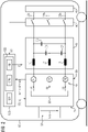
- the figure 1 shows an exemplary embodiment of a rail vehicle 10 that is equipped with a pulse-controlled inverter 20 .
- a DC voltage side 21 of the pulse-controlled inverter 20 is connected to a DC voltage intermediate circuit 30 of the rail vehicle 10 and has a DC voltage Udc applied to it.
- An AC voltage side 22 of the pulse-controlled inverter is connected to a three-phase AC voltage system which comprises three phase conductors 22a, 22b and 22c.
- a three-phase electrical load 40 is connected to the three phase conductors 22a, 22b and 22c, which can be, for example, an internal vehicle electrical system of the rail vehicle 10 or one or more drive components of the rail vehicle 10 .
- Such drive components fed by the pulse-controlled inverter 20 are, for example, one or more drive motors, in particular a three-phase synchronous motor or one or more three-phase asynchronous motors.
- a switching device 50 , a filter device 60 and a current measuring device 70 are connected between the three-phase electrical load 40 and the pulse-controlled inverter 20 .
- the filter device 60 consists of three capacitors C1, C2 and C3 and three inductances L1, L2 and L3.
- the capacitors are connected in a delta configuration.
- the current measuring device 70 has three measuring modules 71, 72 and 73, which are designed to be able to measure the phase currents I1, I2 and I3 in the phase conductors 22a, 22b and 22c both in the load and in the no-load operation of the pulse-controlled inverter 20.
- the figure 1 shows the idling mode, since the switches of the switching device 50 are open.
- a control device 120 is provided for controlling the pulse-controlled inverter 20 .
- the control device 120 comprises a computing device 121 and a memory 122.
- a control program module SPM is stored in the memory 122, which, when executed by the computing device 121, specifies the mode of operation of the control device 120.
- the control device 120 or its control program module SPM is designed in such a way that the control device 120 controls the pulse-controlled inverter 20 with a control signal ST which corresponds to the target frequency fs of the output AC voltages U12, U23 and U13 which are present or are present between the phase conductors 22a, 22b and 22c should, set.
- the target frequency fs is preferably between 1 and 100 Hz and is 50 or 60 Hz, for example.
- the filter device 60 is used to dampen an internal clock frequency with which the pulse-controlled inverter 20 works, so that the internal clock frequency does not occur or occurs only as little as possible in the output AC voltages U12, U23 and U13 present between the phase conductors 22a, 22b and 22c and thus as far as possible acts little on the three-phase electrical load 40.
- the internal clock frequency is preferably usually at least 10 times higher than the target frequency and is, for example, in a range between 1 kHz and 100 kHz.
- control program module SPM the memory 122 of the control device 120 also stores a control module KM, which when executed by the computing device 121 forms a control device integrated in the control device 120 in terms of software.
- the control device or the control module KM preferably receives an actuating signal SS from the switching device 50, which indicates whether the switching device 50 is closed or open.
- the control module KM evaluates measured current values Im1, Im2 and Im3, which are recorded by measuring modules 71, 72 and 73.
- the measuring modules 71, 72 and 73 measure in the exemplary embodiment according to FIG figure 1 the phase currents I1, I2 and I3 in the phase conductors 22a, 22b and 22c.
- the setpoint phase value is preferably obtained by dividing the maximum possible phase difference by the number of phases on the AC voltage side 22.
- ⁇ target 360 ° / AP
- AP denotes the number of phases on the AC voltage side 22.
- the target phase value is 120° or 2 ⁇ /3.
- phase conductor-related phase difference values ⁇ i12, ⁇ i13 and ⁇ i23 or at least one of them deviate from the setpoint phase value ⁇ soll by more than the amount defined by the phase conductor-related maximum difference value ⁇ imax, this is regarded as an indication of an error and an error signal F is generated, which indicates a possible error in the Filter device 60 indicates and maintenance of the filter device 60 triggers.
- error signal F Excessively large deviations in the phase difference values from the setpoint phase value can occur, for example, if a short circuit occurs within at least one of the capacitors or one of the capacitors has been separated from its associated phase conductors.
- control module KM can generate an error signal F if a phase difference value relating to one phase pair deviates from another phase difference value relating to another phase pair by more than the specified amount, i.e. if all or at least one of the following conditions are met: ⁇ ⁇ i12 ⁇ ⁇ ⁇ i13 ⁇ ⁇ ⁇ imax2 ⁇ ⁇ i12 ⁇ ⁇ ⁇ i23 ⁇ ⁇ ⁇ imax2 ⁇ ⁇ i13 ⁇ ⁇ ⁇ i23 ⁇ ⁇ ⁇ imax2 where ⁇ imax2 designates a phase-pair-related maximum differential value.
- the current measuring device 70 is a separate component which is electrically connected between the pulse-controlled inverter 20 and the filter device 60 and is used or suitable for measuring the phase currents I1-I3 in the phase conductors 22a-22c both in load operation and in no-load operation.
- the current measuring device 70 is integrated in the pulse-controlled inverter 20, i.e. the pulse-controlled inverter 20 itself detects the currents flowing in the phase conductors 22a, 22b and 22c and transmits the corresponding measured current values to the control device 120 itself.
- the pulse-controlled inverter 20 itself detects the currents flowing in the phase conductors 22a, 22b and 22c and transmits the corresponding measured current values to the control device 120 itself.
- Such a configuration is exemplified in figure 2 shown.
- the measuring modules 71, 72 and 73 of the current measuring device 70 can also be integrated in the filter device 60, as is exemplified in FIG figure 3 is shown.
- the three measuring modules 71, 72 and 73 are connected to the control device 120 or the control module KM via connecting lines (not shown) so that the control module KM can check the filter device 60, as is the case above in connection with figures 1 and 2 has been explained.
- the capacitor currents flowing through the three capacitors C1, C2 and C3 can advantageously be directly detected and evaluated. This enables a very precise measurement of the capacitor currents and good fault detection, especially for these particularly relevant components.
- phase conductors in the filter device 60 are connected in a delta circuit.
- star point circuits with a star point SP that is variable in potential, that is to say one that is not fixed in terms of potential.
- exemplary embodiments with such a neutral point circuit are shown in FIG figures 4 and 5 .
- control module KM uses the measuring modules 71, 72 and 73 to measure the capacitor currents Ic1, Ic2 and Ic3 flowing through the capacitors C1, C2 and C3 and evaluates the measured current values Imcl, Imc2 and Imc3. As part of this evaluation, the control module KM checks whether the phase angles of the currents indicate correct operation of the filter device 60 .
- ⁇ (Ic1) is a phase value indicative of the phase of the first capacitor current Ic1
- ⁇ (Ic2) is a phase value indicative of the phase of the second capacitor current Ic2
- ⁇ (Ic3) is a phase value indicative of the phase of the third capacitor current Ic3
- ⁇ ic12 is the phase difference between the first and second capacitor currents
- ⁇ ic13 is
- phase difference values ⁇ ic12, ⁇ ic13 and ⁇ ic23 related to the capacitor current, or at least one of them deviate from the setpoint phase value ⁇ soll by more than the amount defined by the maximum difference value ⁇ icmax related to the capacitor current, this is regarded as an indication of an error and an error signal F is generated, which indicates a possible error in the Filter device 60 indicates and maintenance of the filter device 60 triggers.
- Error signal F Excessively large deviations in the capacitor current-related phase difference values from the setpoint phase value can occur, for example, if a short circuit occurs within at least one of the capacitors or one of the capacitors has been separated from its associated phase conductors.
- control module KM can generate an error signal F if a phase difference value relating to the capacitor current relating to one phase pair deviates in absolute terms from another phase difference value relating to the capacitor current relating to another phase pair by more than the specified amount, i.e. if all or at least one of the following conditions are met are: ⁇ ⁇ ic12 ⁇ ⁇ ⁇ ic13 ⁇ ⁇ ⁇ icmax2 ⁇ ⁇ ic12 ⁇ ⁇ ⁇ ic23 ⁇ ⁇ ⁇ icmax2 ⁇ ⁇ ic13 ⁇ ⁇ ⁇ ic23 ⁇ ⁇ ⁇ icmax2 where ⁇ icmax2 designates a phase pair and capacitor current related maximum differential value.
- control module KM measures the capacitor voltages Uc1, Uc2 and Uc3 present at the capacitors C1, C2 and C3 using measuring modules that are not shown, and evaluates the measured voltage values Umc1, Umc2 and Umc3.
- control module KM can generate an error signal F if a voltage-related phase difference value relating to one phase pair deviates in absolute terms from another voltage-related phase difference value relating to another phase pair by more than the specified amount, i.e. if all or at least one of the following conditions are met are: ⁇ ⁇ uc12 ⁇ ⁇ ⁇ uc13 ⁇ ⁇ ⁇ ucmax2 ⁇ ⁇ uc12 ⁇ ⁇ ⁇ uc23 ⁇ ⁇ ⁇ ucmax2 ⁇ ⁇ uc13 ⁇ ⁇ ⁇ uc23 ⁇ ⁇ ⁇ ucmax2 where ⁇ ucmax2 designates a phase pair and capacitor voltage-related maximum differential value.
- phase position check for fault detection was explained as an example for no-load operation, in which the load 40 is separated from the filter device 60 and the pulse-controlled inverter 20.
- the error check can also be carried out in load operation, in which the load 40 is connected to the filter device 60 and the pulse-controlled inverter 20 .
- the phase conductor-related maximum difference value ⁇ imax, the capacitor current-related maximum difference value ⁇ icmax and the voltage-related maximum difference value ⁇ ucmax are preferably each in a range between 1° and 10°.
- phase conductor-related maximum differential value ⁇ imax, the capacitor current-related Maximum differential value ⁇ icmax and the voltage-related maximum differential value ⁇ ucmax are adapted to the respective operating mode, ie different maximum differential values are selected for load operation than for no-load operation.
- the maximum difference values for the load operation are selected to be greater, preferably at least 10% greater, than the maximum difference values for the no-load operation, in order to take into account a possible falsification of the measurement results due to the influence of the load 40 .
Landscapes
- Engineering & Computer Science (AREA)
- Power Engineering (AREA)
- Inverter Devices (AREA)
Applications Claiming Priority (1)
| Application Number | Priority Date | Filing Date | Title |
|---|---|---|---|
| DE102021205467.6A DE102021205467A1 (de) | 2021-05-28 | 2021-05-28 | Anordnung mit Pulswechselrichter |
Publications (1)
| Publication Number | Publication Date |
|---|---|
| EP4096079A1 true EP4096079A1 (fr) | 2022-11-30 |
Family
ID=81648299
Family Applications (1)
| Application Number | Title | Priority Date | Filing Date |
|---|---|---|---|
| EP22172947.8A Pending EP4096079A1 (fr) | 2021-05-28 | 2022-05-12 | Agencement d'essai fonctionnel des condensateurs d'un dispositif filtre d'un véhicule |
Country Status (2)
| Country | Link |
|---|---|
| EP (1) | EP4096079A1 (fr) |
| DE (1) | DE102021205467A1 (fr) |
Cited By (1)
| Publication number | Priority date | Publication date | Assignee | Title |
|---|---|---|---|---|
| US20210148994A1 (en) * | 2019-11-18 | 2021-05-20 | Marco Bohlländer | Identification of an inverter short circuit between two phases |
Citations (3)
| Publication number | Priority date | Publication date | Assignee | Title |
|---|---|---|---|---|
| JP2010233425A (ja) * | 2009-03-30 | 2010-10-14 | Fujitsu General Ltd | コンデンサの劣化検出回路及びこれを備えた電子機器 |
| EP2919024A1 (fr) * | 2014-03-11 | 2015-09-16 | Rockwell Automation Technologies, Inc. | Identification de la dégradation d'un condensateur de filtre au moyen d'un courant calculé |
| EP3242383A1 (fr) * | 2016-05-03 | 2017-11-08 | ABB Technology Oy | Procédé de surveillance de changement de capacité de filtre à courant alternatif dans un système électrique et système électrique |
Family Cites Families (2)
| Publication number | Priority date | Publication date | Assignee | Title |
|---|---|---|---|---|
| DE102010040835A1 (de) | 2010-09-15 | 2012-03-15 | Robert Bosch Gmbh | Filter für eine Dreiphasenwechselspannung und einen Dreiphasenwechselstrom und Verfahren zum Filtern einer Dreiphasenwechselspannung und eines Dreiphasenwechselstroms |
| DE102015101766A1 (de) | 2015-02-06 | 2016-08-11 | Woodward Kempen Gmbh | Filterüberwachung |
-
2021
- 2021-05-28 DE DE102021205467.6A patent/DE102021205467A1/de active Pending
-
2022
- 2022-05-12 EP EP22172947.8A patent/EP4096079A1/fr active Pending
Patent Citations (3)
| Publication number | Priority date | Publication date | Assignee | Title |
|---|---|---|---|---|
| JP2010233425A (ja) * | 2009-03-30 | 2010-10-14 | Fujitsu General Ltd | コンデンサの劣化検出回路及びこれを備えた電子機器 |
| EP2919024A1 (fr) * | 2014-03-11 | 2015-09-16 | Rockwell Automation Technologies, Inc. | Identification de la dégradation d'un condensateur de filtre au moyen d'un courant calculé |
| EP3242383A1 (fr) * | 2016-05-03 | 2017-11-08 | ABB Technology Oy | Procédé de surveillance de changement de capacité de filtre à courant alternatif dans un système électrique et système électrique |
Cited By (2)
| Publication number | Priority date | Publication date | Assignee | Title |
|---|---|---|---|---|
| US20210148994A1 (en) * | 2019-11-18 | 2021-05-20 | Marco Bohlländer | Identification of an inverter short circuit between two phases |
| US11762037B2 (en) * | 2019-11-18 | 2023-09-19 | Rolls-Royce Deutschland Ltd & Co Kg | Identification of an inverter short circuit between two phases |
Also Published As
| Publication number | Publication date |
|---|---|
| DE102021205467A1 (de) | 2022-12-01 |
Similar Documents
| Publication | Publication Date | Title |
|---|---|---|
| DE102010010042B4 (de) | System und Verfahren zum Detektieren eines Isolationsverlusts in einem Motorsystem mit einem Wechselrichter | |
| WO2011157468A1 (fr) | Procédé et dispositif pour surveiller la résistance d'isolation dans un réseau électrique non mis à la terre | |
| DE102011014561B4 (de) | Verfahren und Vorrichtung zum Überwachen einer Elektromotor-Steuerschaltung | |
| DE102018217116B3 (de) | Hochvoltsystem und Verfahren zur Überwachung von Isolationsfehlern in einem Hochvoltsystem | |
| DE102015106069A1 (de) | Elektrische Motoransteuerungsvorrichtung | |
| DE102017205521B4 (de) | Energiewandlungsvorrichtung und Verfahren zum Diagnostizieren von Abnormalität in Spannungssensorcharakteristika | |
| EP1876455A1 (fr) | Procédé destiné à la mesure de la résistance d'isolement dans un réseau IT | |
| EP1909369A2 (fr) | Agencement de commutation et procédé de surveillance d'isolation pour des applications de convertisseur en fonctionnement | |
| DE102010061933A1 (de) | Verfahren zum Nachweis eines Kabelbruchs eines Motors | |
| DE102013213802A1 (de) | Überspannungsschutz für aktive Gleichrichter bei Lastabwurf | |
| WO2014202326A1 (fr) | Procédé de contrôle de la fonctionnalité d'un circuit intermédiaire | |
| EP4096079A1 (fr) | Agencement d'essai fonctionnel des condensateurs d'un dispositif filtre d'un véhicule | |
| WO2011157472A1 (fr) | Montage pour déterminer une variation de tension de potentiels de conducteur dans un réseau électrique non mis à la terre | |
| WO2015010951A1 (fr) | Procédé permettant d'accoupler au moins une source d'énergie secondaire à un réseau d'alimentation en énergie, en particulier un réseau de bord d'un véhicule | |
| DE102019217748A1 (de) | Ermitteln eines Inverterkurzschlusses Phase-gegen-Masse | |
| DE102017221635B4 (de) | Ermitteln einer Netzsystemart einer Energiequelle zum Aufladen eines elektrischen Energiespeichers | |
| WO2018007106A1 (fr) | Procédé permettant de détecter une panne dans un réseau de bord | |
| EP4102704A1 (fr) | Agencement d'essai fonctionnel des condensateurs d'un dispositif de filtre d'un véhicule | |
| DE102010030083A1 (de) | Schaltungsanordnung zur Bestimmung einer Spannungsschwankung von Leiterpotentialen in einem ungeerdeten elektrischen Netz | |
| DE102019217747A1 (de) | Ermitteln eines Inverterkurzschlusses zwischen zwei Phasen | |
| WO2011157469A1 (fr) | Montage pour déterminer une variation de tension de potentiels de conducteur dans un réseau électrique non mis à la terre | |
| EP1695104B1 (fr) | Procede et ensemble pour tester un etage de sortie de puissance | |
| DE102019131121B4 (de) | Fahrzeugantriebsvorrichtung | |
| DE102021205406B4 (de) | Gleichspannungs-Fehlerstromüberwachung zur Erfassung eines Isolationsfehlers | |
| DE102017211219A1 (de) | Verfahren und Vorrichtung zum Betreiben einer elektrischen Maschine, insbesondere eines Lenkunterstützungsantriebs |
Legal Events
| Date | Code | Title | Description |
|---|---|---|---|
| PUAI | Public reference made under article 153(3) epc to a published international application that has entered the european phase |
Free format text: ORIGINAL CODE: 0009012 |
|
| STAA | Information on the status of an ep patent application or granted ep patent |
Free format text: STATUS: THE APPLICATION HAS BEEN PUBLISHED |
|
| AK | Designated contracting states |
Kind code of ref document: A1 Designated state(s): AL AT BE BG CH CY CZ DE DK EE ES FI FR GB GR HR HU IE IS IT LI LT LU LV MC MK MT NL NO PL PT RO RS SE SI SK SM TR |
|
| STAA | Information on the status of an ep patent application or granted ep patent |
Free format text: STATUS: REQUEST FOR EXAMINATION WAS MADE |
|
| 17P | Request for examination filed |
Effective date: 20230530 |
|
| RBV | Designated contracting states (corrected) |
Designated state(s): AL AT BE BG CH CY CZ DE DK EE ES FI FR GB GR HR HU IE IS IT LI LT LU LV MC MK MT NL NO PL PT RO RS SE SI SK SM TR |
|
| STAA | Information on the status of an ep patent application or granted ep patent |
Free format text: STATUS: EXAMINATION IS IN PROGRESS |
|
| 17Q | First examination report despatched |
Effective date: 20240201 |