EP4096072A1 - Motor - Google Patents
Motor Download PDFInfo
- Publication number
- EP4096072A1 EP4096072A1 EP21744824.0A EP21744824A EP4096072A1 EP 4096072 A1 EP4096072 A1 EP 4096072A1 EP 21744824 A EP21744824 A EP 21744824A EP 4096072 A1 EP4096072 A1 EP 4096072A1
- Authority
- EP
- European Patent Office
- Prior art keywords
- disposed
- shaft
- yoke
- mirror
- holder
- Prior art date
- Legal status (The legal status is an assumption and is not a legal conclusion. Google has not performed a legal analysis and makes no representation as to the accuracy of the status listed.)
- Pending
Links
Images

























Classifications
-
- G—PHYSICS
- G01—MEASURING; TESTING
- G01S—RADIO DIRECTION-FINDING; RADIO NAVIGATION; DETERMINING DISTANCE OR VELOCITY BY USE OF RADIO WAVES; LOCATING OR PRESENCE-DETECTING BY USE OF THE REFLECTION OR RERADIATION OF RADIO WAVES; ANALOGOUS ARRANGEMENTS USING OTHER WAVES
- G01S7/00—Details of systems according to groups G01S13/00, G01S15/00, G01S17/00
- G01S7/48—Details of systems according to groups G01S13/00, G01S15/00, G01S17/00 of systems according to group G01S17/00
- G01S7/481—Constructional features, e.g. arrangements of optical elements
- G01S7/4817—Constructional features, e.g. arrangements of optical elements relating to scanning
-
- G—PHYSICS
- G01—MEASURING; TESTING
- G01D—MEASURING NOT SPECIALLY ADAPTED FOR A SPECIFIC VARIABLE; ARRANGEMENTS FOR MEASURING TWO OR MORE VARIABLES NOT COVERED IN A SINGLE OTHER SUBCLASS; TARIFF METERING APPARATUS; MEASURING OR TESTING NOT OTHERWISE PROVIDED FOR
- G01D5/00—Mechanical means for transferring the output of a sensing member; Means for converting the output of a sensing member to another variable where the form or nature of the sensing member does not constrain the means for converting; Transducers not specially adapted for a specific variable
- G01D5/12—Mechanical means for transferring the output of a sensing member; Means for converting the output of a sensing member to another variable where the form or nature of the sensing member does not constrain the means for converting; Transducers not specially adapted for a specific variable using electric or magnetic means
- G01D5/14—Mechanical means for transferring the output of a sensing member; Means for converting the output of a sensing member to another variable where the form or nature of the sensing member does not constrain the means for converting; Transducers not specially adapted for a specific variable using electric or magnetic means influencing the magnitude of a current or voltage
- G01D5/20—Mechanical means for transferring the output of a sensing member; Means for converting the output of a sensing member to another variable where the form or nature of the sensing member does not constrain the means for converting; Transducers not specially adapted for a specific variable using electric or magnetic means influencing the magnitude of a current or voltage by varying inductance, e.g. by a movable armature
- G01D5/2006—Mechanical means for transferring the output of a sensing member; Means for converting the output of a sensing member to another variable where the form or nature of the sensing member does not constrain the means for converting; Transducers not specially adapted for a specific variable using electric or magnetic means influencing the magnitude of a current or voltage by varying inductance, e.g. by a movable armature by influencing the self-induction of one or more coils
-
- G—PHYSICS
- G01—MEASURING; TESTING
- G01S—RADIO DIRECTION-FINDING; RADIO NAVIGATION; DETERMINING DISTANCE OR VELOCITY BY USE OF RADIO WAVES; LOCATING OR PRESENCE-DETECTING BY USE OF THE REFLECTION OR RERADIATION OF RADIO WAVES; ANALOGOUS ARRANGEMENTS USING OTHER WAVES
- G01S17/00—Systems using the reflection or reradiation of electromagnetic waves other than radio waves, e.g. lidar systems
- G01S17/02—Systems using the reflection of electromagnetic waves other than radio waves
- G01S17/06—Systems determining position data of a target
- G01S17/08—Systems determining position data of a target for measuring distance only
- G01S17/10—Systems determining position data of a target for measuring distance only using transmission of interrupted, pulse-modulated waves
-
- H—ELECTRICITY
- H02—GENERATION; CONVERSION OR DISTRIBUTION OF ELECTRIC POWER
- H02K—DYNAMO-ELECTRIC MACHINES
- H02K11/00—Structural association of dynamo-electric machines with electric components or with devices for shielding, monitoring or protection
- H02K11/20—Structural association of dynamo-electric machines with electric components or with devices for shielding, monitoring or protection for measuring, monitoring, testing, protecting or switching
- H02K11/21—Devices for sensing speed or position, or actuated thereby
- H02K11/215—Magnetic effect devices, e.g. Hall-effect or magneto-resistive elements
-
- H—ELECTRICITY
- H02—GENERATION; CONVERSION OR DISTRIBUTION OF ELECTRIC POWER
- H02K—DYNAMO-ELECTRIC MACHINES
- H02K21/00—Synchronous motors having permanent magnets; Synchronous generators having permanent magnets
- H02K21/12—Synchronous motors having permanent magnets; Synchronous generators having permanent magnets with stationary armatures and rotating magnets
- H02K21/22—Synchronous motors having permanent magnets; Synchronous generators having permanent magnets with stationary armatures and rotating magnets with magnets rotating around the armatures, e.g. flywheel magnetos
-
- H—ELECTRICITY
- H02—GENERATION; CONVERSION OR DISTRIBUTION OF ELECTRIC POWER
- H02K—DYNAMO-ELECTRIC MACHINES
- H02K5/00—Casings; Enclosures; Supports
- H02K5/04—Casings or enclosures characterised by the shape, form or construction thereof
- H02K5/16—Means for supporting bearings, e.g. insulating supports or means for fitting bearings in the bearing-shields
- H02K5/173—Means for supporting bearings, e.g. insulating supports or means for fitting bearings in the bearing-shields using bearings with rolling contact, e.g. ball bearings
- H02K5/1735—Means for supporting bearings, e.g. insulating supports or means for fitting bearings in the bearing-shields using bearings with rolling contact, e.g. ball bearings radially supporting the rotary shaft at only one end of the rotor
-
- H—ELECTRICITY
- H02—GENERATION; CONVERSION OR DISTRIBUTION OF ELECTRIC POWER
- H02K—DYNAMO-ELECTRIC MACHINES
- H02K7/00—Arrangements for handling mechanical energy structurally associated with dynamo-electric machines, e.g. structural association with mechanical driving motors or auxiliary dynamo-electric machines
- H02K7/003—Couplings; Details of shafts
-
- H—ELECTRICITY
- H02—GENERATION; CONVERSION OR DISTRIBUTION OF ELECTRIC POWER
- H02K—DYNAMO-ELECTRIC MACHINES
- H02K7/00—Arrangements for handling mechanical energy structurally associated with dynamo-electric machines, e.g. structural association with mechanical driving motors or auxiliary dynamo-electric machines
- H02K7/08—Structural association with bearings
- H02K7/085—Structural association with bearings radially supporting the rotary shaft at only one end of the rotor
-
- H—ELECTRICITY
- H02—GENERATION; CONVERSION OR DISTRIBUTION OF ELECTRIC POWER
- H02K—DYNAMO-ELECTRIC MACHINES
- H02K7/00—Arrangements for handling mechanical energy structurally associated with dynamo-electric machines, e.g. structural association with mechanical driving motors or auxiliary dynamo-electric machines
- H02K7/14—Structural association with mechanical loads, e.g. with hand-held machine tools or fans
-
- H—ELECTRICITY
- H02—GENERATION; CONVERSION OR DISTRIBUTION OF ELECTRIC POWER
- H02K—DYNAMO-ELECTRIC MACHINES
- H02K2211/00—Specific aspects not provided for in the other groups of this subclass relating to measuring or protective devices or electric components
- H02K2211/03—Machines characterised by circuit boards, e.g. pcb
Definitions
- Embodiments relate to a motor.
- a motor may include a rotor, a stator and a shaft.
- the shaft is coupled to the rotor.
- the rotor may be disposed outside of the stator. The rotor rotates via the electromagnetic interaction between the rotor and the stator, and when the rotor rotates, the shaft rotates.
- the shaft may connect a sensor device (e.g., light detection and ranging (LiDAR)).
- a sensor device e.g., light detection and ranging (LiDAR)
- the motor may include a sensor configured to sense a change in a magnetic flux of a drive magnet disposed in the rotor.
- a separate sensing magnet which is multi-polar magnetized may be disposed to increase resolution and a sensor configured to sense the change in the magnetic flux therefrom may be provided.
- These sensors may be mounted on a substrate.
- the substrate may be mounted on a base plate.
- a bearing configured to support the shaft may be provided, and the bearing may be received in a bearing housing.
- the bearing housing may be coupled to the base plate.
- the bearing housing is made of aluminum or brass
- the base plate is made of a steel plate.
- the bearing housing needs to secure rigidity to support a shaft via the bearing. Accordingly, the bearing housing has to be designed to have a thickness greater than or equal to a certain thickness. However, with an increase in the thickness of the bearing housing, there is a problem that the design of other components is restrained. In addition, since the materials of the bearing housing and the base plate differ from each other, a press-fit part or a caulking part is continuously stressed by temperature and external force, resulting in a structurally weak problem.
- a sensor device may be a device that senses a pulse returned when an emitted light pulse is reflected by hitting an object.
- the sensor device in order to emit the light pulse, the sensor device may include a mirror.
- the mirror is connected to the rotor via a holder. When the rotor rotates, the holder rotates, and the mirror fixed to the holder rotates as well.
- the mirror needs to have a sufficient height in an axial direction for the purpose of sufficiently securing a field of view of the sensor device.
- regular speed driving of the motor may be an important factor that secures the performance of the sensor device.
- the regular speed driving of the motor may be determined by detecting the position of a rotating rotor.
- the motor may include a hall sensor configured to sense the change in the magnetic flux of the drive magnet disposed in the rotor.
- sensing the change in the magnetic flux caused by a general drive magnet has a limitation in satisfying the regular speed condition of the motor.
- a separate multi-polar magnetized sensing magnet needs to be additionally disposed in order to increase the resolution.
- the stator is disposed under the mirror in the axial direction, there is a problem in that the height of the mirror may not be sufficiently secured due to the height of the stator.
- the mirror is fixed to the holder through an adhesive.
- the mirror fixed with an adhesive has a weak bonding force, it may be separated from the holder due to external force or vibration. Specifically, there is a risk that the mirror may be separated from the holder while the performance of the adhesive decreases due to temperature and humidity conditions.
- the guide may cover a coating layer disposed on a front surface of the mirror in a process of coupling the guide to the mirror, resulting in reducing sensing performance.
- the embodiments are intended to solve the aforementioned problems and provide a motor with a high structural rigidity and a high degree of design freedom.
- the embodiments also provide a motor that can reduce the size and weight of the entire motor while sufficiently securing an axial length of a mirror.
- the embodiments also provide a motor that can accurately recognize a position of a rotor in a simple configuration without an additional sensing magnet.
- the embodiments also provide a motor that ensure sensing performance while firmly fixing a mirror to a holder.
- An embodiment may provide a motor comprising: a shaft; a rotor coupled to the shaft and a stator disposed between the shaft and the rotor; a bearing disposed between the shaft and the stator; and a base plate, wherein the rotor includes a yoke coupled to the shaft; the base plate includes a body, a first partition protruding from the body, and a second partition extending from the first partition; the first partition is disposed between the bearing and the stator; a portion of the second partition is disposed to be overlapped with the first partition; and the first partition is in contact with a lateral surface of an outer ring of the bearing and the second partition is in contact with one surface of the outer ring of the bearing.
- An embodiment may provide a motor comprising a shaft; a rotor coupled to the shaft and a stator disposed between the shaft and the rotor; a bearing disposed between the shaft and the stator; and a base plate, wherein the rotor includes a yoke coupled to the shaft, the yoke includes a first hole penetrated by the shaft, the base plate includes a second hole penetrated by the shaft, an inner diameter of the second hole is larger than an inner diameter of the first hole, the shaft is in contact with an inner surface of the first hole, and an outer surface of the bearing is in contact with an inner surface of the second hole.
- the yoke may include an extension part in contact with the shaft, and in a radial direction, the second partition may be disposed to be overlapped with the extension part.
- At least a portion of the first partition may be disposed to be overlapped with the stator.
- a curved surface disposed in a boundary between the body and the first partition may be provided.
- a distance from the body to an upper end of the first partition may exceed a length of the bearing and may be less than the longest distance from the body to the yoke in an axial direction.
- the rotor may further include a drive magnet and a sensing magnet coupled to the yoke, and at least a portion of the first partition in the radial direction may be disposed to be overlapped with the stator, the drive magnet and the sensing magnet.
- a portion of the base plate may be disposed to be overlapped with the bearing.
- a portion of the base plate may be disposed to be overlapped with the yoke.
- a distance in the radial direction between an inner surface of an inner ring of the bearing and an outer surface of the outer ring, in the radial direction may be the same as a difference between the inner diameter of the second hole and the inner diameter of the first hole.
- An embodiment provides a motor comprising: a shaft; a rotor coupled to the shaft; a stator disposed between the shaft and the rotor; a connection member including a first surface and a second surface and disposed on the rotor; a holder disposed on the connection member; and a mirror coupled to the holder, wherein the rotor includes a yoke coupled to the shaft, and the first surface is in contact with the holder, and the second surface is in contact with the yoke.
- connection member may be disposed to be overlapped with the mirror in the radial direction.
- the mirror and the yoke may be disposed to be overlapped in the radial direction.
- the mirror may include a first mirror and a second mirror
- the holder may include a first member coupled to the first mirror, a second member coupled to the second mirror, and a third member connecting the first member and the second member, wherein the first surface may be in contact with the third member, and the second surface may be in contact with an upper surface of the yoke.
- the yoke may include a first hole disposed on the upper surface of the yoke penetrated by the shaft, and the connection member may be press-fitted into the first hole and coupled to the yoke, and may be coupled to the holder via a fastening member.
- the yoke may include a second hole disposed on the upper surface of the yoke, and a portion of the fastening member may be disposed to be overlapped with the second hole in the radial direction.
- connection member may include a third hole penetrated by the fastening member, and a screw tab may be disposed on an inner surface of the third hole.
- connection member may include a body including the first surface and the second surface, and a protrusion protruding from the second surface and disposed inside the first hole.
- the first member may include a third surface in contact with the first mirror and a first groove concavely disposed on the third surface
- the second member may include a fourth surface in contact with the second mirror and a second groove concavely disposed on the fourth surface
- an adhesive may be disposed in the first groove and the second groove.
- each of the first groove and the second groove may have an axial length greater than a length in a width direction.
- the third member may include a fourth hole penetrated by the shaft and a fifth hole penetrated by the fastening member.
- the second hole, the third hole, and the fifth hole may be disposed to correspond to each other in the axial direction.
- the first member may include a fifth surface facing the first surface and a third groove concavely disposed on the fifth surface
- the second member may include a sixth surface facing the second surface and a fourth groove concavely disposed on the sixth surface
- one portion of the yoke may be disposed in the third groove and the other portion of the yoke may be disposed in the fourth groove.
- An embodiment may provide a motor comprising: a shaft; a rotor coupled to the shaft; a stator disposed in the rotor; and a substrate on which a sensor is disposed, wherein the rotor includes a yoke and a magnet coupled to the yoke, the yoke includes a body and a flange extending from the body, the flange includes a plurality of first edges and a plurality of second edges alternately disposed along a circumferential direction of the yoke, and the second edge is disposed closer to the body than the first edge in the radial direction of the yoke.
- the substrate may include a coil electrically connected to the sensor, and the sensor may be disposed to correspond to the magnet.
- the coil may be a pattern coil.
- the stator may be disposed between the shaft and the rotor.
- the yoke may be coupled to the shaft.
- the magnet may be disposed on an inner circumferential surface of the body.
- the first edge may be disposed on an outer side of the coil.
- At least a portion of the coil may be disposed between the first edge and the second edge in the radial direction of the yoke.
- the first edge and the second edge may be curved, and the second edge may be disposed on an outer circumferential surface of the body.
- the flange may include a third edge connecting the first edge and the second edge, and the third edge may be disposed along the radial direction of the yoke.
- the thickness of the body may be the same as that of the flange.
- the magnet and the flange may be disposed to be overlapped in the radial direction of the yoke.
- a base on which the substrate is disposed, a bearing housing connected to the base, and a bearing disposed inside the bearing housing may be further included, and the stator may be coupled to an outer side of the bearing housing, and the shaft may be rotatably supported by the bearing.
- the flange may be disposed to be overlapped with the bearing housing in the radial direction of the yoke.
- each of the plurality of first edges may have the same circumferential length, and the plurality of second edges may have the same circumferential length.
- An embodiment may provide a motor comprising: a shaft; a rotor coupled to the shaft and including a yoke; a stator disposed in the rotor; a connection member disposed on the rotor; a holder coupled to the connection member; a mirror coupled to the holder; a bearing housing coupled to the stator; and a first bearing and a second bearing disposed in the bearing housing, wherein the first bearing is disposed between the bearing housing and the yoke, and the second bearing is disposed between the shaft and the bearing housing, and the stator is disposed to be overlapped with the mirror in a radial direction.
- An embodiment may provide a motor comprising: a shaft; a rotor coupled to the shaft; a stator disposed in the rotor; a connection member disposed on the rotor; a holder disposed on the connection member; a mirror coupled to the holder; a bearing housing coupled to the stator; and a first bearing and a second bearing disposed on the bearing housing, wherein the first bearing is disposed to be overlapped with the mirror in a radial direction, the second bearing is disposed not to be overlapped with the mirror in the radial direction, and an inner diameter of the first bearing may provide a motor larger than an inner diameter of the second bearing.
- An embodiment may provide a motor comprising: a shaft; a rotor coupled to the shaft; a stator disposed in the rotor; a connection member disposed on the rotor; a holder disposed on the connection member; a first mirror and a second mirror coupled to the holder; a bearing housing coupled to the stator; and a first bearing disposed on the bearing housing, wherein the rotor includes a yoke coupled to the shaft and a magnet disposed in the yoke, the yoke includes a magnet receiving part in which the magnet is disposed and a pillar part in contact with the first bearing.
- An outer diameter of the magnet receiving part may be larger than an outer diameter of the pillar part, and smaller than the shortest distance between the first mirror and the second mirror.
- the first bearing may be disposed to be overlapped with the mirror in a radial direction
- the second bearing may be disposed not to be overlapped with the mirror in the radial direction
- the magnet may be disposed to be overlapped with the first mirror and the second mirror.
- an inner diameter of the stator may be smaller than an outer diameter of the first bearing, and an inner diameter of the second bearing may be smaller than an inner diameter of the first bearing.
- the bearing housing may include a first region in contact with the stator and a second region in contact with the first bearing, and an outer diameter of the first region may be larger than an outer diameter of the second region.
- the bearing housing may include a third region in contact with the second bearing, and an inner diameter of the third region may be larger than the outer diameter of the first region.
- the stator may include a stator core, and an inner diameter of the stator may be smaller than the outer diameter of the first bearing.
- connection member may include a first surface and a second surface, wherein the first surface may be in contact with the holder and the second surface may be in contact with the yoke.
- An embodiment may provide a motor comprising: a shaft; a rotor coupled to a shaft and including a yoke; a stator disposed in the rotor; a connection member disposed on the rotor; a holder disposed on the connection member; and a mirror coupled to the holder, wherein the holder includes a first surface in contact with a rear surface of the mirror and a first protrusion disposed to protrude rather than the first surface, and the first protrusion is in contact with one of a side surface and a front surface of the mirror.
- the holder may include a body including the first surface and a bracket coupled to the body, the bracket may include the first protrusion, and the first protrusion may be in contact with both side surfaces of the mirror.
- the holder may include a second protrusion protruding rather than the first surface, and the second protrusion may be in contact with an upper surface or a lower surface of the mirror.
- the height of the mirror may exceed the height of the bracket and less than a height of the holder.
- the bracket may include a bracket body in contact with the holder, and a clip part bent from the bracket body to contact a side surface of the mirror.
- the side surface of the mirror may include a first side part inclined with regard to a front surface of the mirror, and the clip part may be in contact with the first side part.
- the holder may include a body including the first surface and a bracket coupled to the body, the bracket may include the first protrusion, and the first protrusion may be in contact with the front surface of the mirror.
- the bracket may include a bracket body in contact with the holder and a clip part bent from the bracket body to contact the front surface of the mirror.
- the first protrusion may include a first-first protrusion in contact with one-side surface of the mirror and a first-second protrusion in contact with the other-side surface of the mirror
- the holder may include a body including the first surface and the first protrusion, and the body may include a first part and a second part coupled to the first part. A portion of the first surface may be disposed in the first part, the remaining portion of the first surface may be disposed in the second part.
- the first-first protrusion may be disposed in the first part, and the first-second protrusion may be disposed in the second part.
- the first part and the second part may be disposed symmetrically with regard to the center of a width of the mirror.
- the holder may include a first screw and a second screw coupled across the first part and the second part.
- a head of the first screw may be in contact with the first part, and a head of the second screw may be in contact with the second part.
- the thickness of the first protrusion may be identical to the thickness of the mirror.
- the first protrusion may include a first-first protrusion in contact with one-side surface of the side surfaces of the mirror and a first-second protrusion in contact with the other-side surface of the side surfaces of the mirror.
- the holder may include a body including the first surface and the protrusion, and the body may include a third part, a fourth part coupled to the third part, and a fifth part coupled to the fourth part.
- the first surface may be disposed in the third part
- the first protrusion may be disposed in the fourth part
- the second protrusion may be disposed in the fifth part.
- the third part and the fourth part may be spaced apart from a rear surface of the mirror.
- the side surface of the mirror may include a third side surface connected to the front surface of the mirror and a fourth side connected to the rear surface of the mirror.
- the third side surface and the fourth side surface may be connected using a stepped surface, and the first protrusion may be in contact with the stepped surface.
- a portion of the mirror and a portion of the first protrusion may be disposed to overlap each other with regard to the thickness direction of the mirror.
- a portion of the base plate may support the bearing, thereby providing a high structural rigidity and a high degree of design freedom.
- the bearing housing may be removed to facilitate assembly and tolerance management.
- a portion of the base plate may support the bearing, thereby providing high structural rigidity.
- the weight and size of the motor may be reduced while sufficiently securing the axial length of the mirror.
- connection member which is a single component.
- the adhesive since the grooves where the adhesive is located on a surface of the holder in contact with the mirror are elongated in the axial direction, the adhesive may be easily applied and easily cured.
- the holder and the connection member may be arranged so that a portion of the fastening member overlaps an upper surface of the yoke of the rotor in a radial direction, thereby preventing slip from occurring in the rotating direction between the holder and the rotor.
- the protrusion of the connection member may be press-fitted into the yoke, thereby facilitating assembly.
- the number of components for sensing the position of the rotor may be greatly reduced, thereby resulting in simple configuration.
- the yoke configured to fix the magnet may be adapted to sense the position of the rotor using magnetic induction, thereby reducing the number of components.
- the yoke flange may be employed to detect the position of the rotor, thereby providing high degree of design freedom and high availability.
- an advantage here is that there is no magnetic field interference with the drive magnet.
- the winding space of the stator for the coil may be ensured even while reducing the outer diameter of the stator so that the axial length of the mirror increases, thereby ensuring a torque of the motor.
- a relatively large first bearing may rotatably support the yoke, thereby having a high robustness of an axial structure.
- the coating disposed on the front surface of the mirror is not covered while fixing the mirror to the holder, sensing performance may be ensured.
- a direction parallel to a longitudinal direction (up-and-down direction) of a shaft is referred to as an axial direction, while a direction perpendicular to the axial direction around the shaft is referred to as a radial direction, and a direction along a circle with a radial radius around the shaft is referred to as a circumferential direction.
- FIG. 1 is a perspective view illustrating a motor according to one embodiment
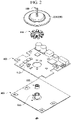
- FIG. 2 is an exploded perspective view of the motor shown in FIG. 1
- FIG. 3 is a side sectional view of the motor taken along line A-A in FIGFIG. 1.
- an inner side is a direction facing a shaft 100 on the basis of the radial direction x of the motor
- an outer side is a direction opposite to the inner side.
- an x-axis represents the radial direction
- a z-axis represents the axial direction.
- a motor may include the shaft 100, a rotor 200, and a stator 300.
- the shaft 100 is coupled to a yoke 210 of the rotor 200.
- the shaft 100 may be press-fitted and coupled to the yoke 210.
- the shaft 100 may be integrated with the yoke 210.
- the shaft 100 rotates with the rotor 200.
- the shaft 100 is rotatably supported by a bearing 600.
- the rotor 200 may include the yoke 210, a drive magnet 220, and a sensing magnet 230.
- the yoke 210 is coupled to the shaft 100.
- the shaft 100 may be disposed at the center of the yoke 210.
- the drive magnet 220 is for rotating the yoke 210.
- the drive magnet 220 may be disposed on an inner surface of the yoke 210.
- the drive magnet 220 may be disposed to face the stator 300 in the radial direction x of the rotor 200. When an electrical interaction occurs between the drive magnet 220 and a coil of the stator 300, the yoke 210 rotates.
- the drive magnet 220 may be a combination of a plurality of unit magnets. Alternatively, the drive magnet 220 may be a single component with a ring shape.
- the sensing magnet 230 is for precisely recognizing a position of the rotor 200.
- the sensing magnet 230 may be disposed on the inner surface of the yoke 210.
- the sensing magnet 230 may be disposed to face a substrate 400 in an axial direction z.
- the stator 300 may be disposed between the shaft 100 and the yoke 210.
- the stator 300 may be fixed to an outer surface of a first partition 520 (in FIG. 7 ) of a base plate 500.
- the stator 300 may include a core of the stator 300 including a plurality of teeth, and the coil may be wound around each tooth.
- the teeth may include an insulator configured to insulate the coil and the core of the stator 300.
- the substrate 400 is disposed on one side of the yoke 210.
- the substrate 400 may include a sensor 410.
- the sensor 410 may be a Hall IC or an encoder IC that senses a change in a magnetic flux of the sensing magnet 230.
- the sensor 410 may be disposed to face the drive magnet 220 or the sensing magnet 230 in the axial direction z.
- the substrate 400 may be mounted on one surface of the base plate 500.
- the bearing 600 rotatably supports the shaft 100.
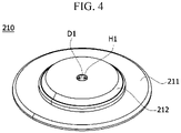
- FIG. 4 is a perspective view illustrating the yoke 210.
- the yoke 210 may include a base 211 and a magnet receiving part 212.
- the yoke 210 may be a cylindrical member where one side and the other side thereof are opened as a whole.
- the magnet receiving part 212 may protrude from the base 211.
- the base 211 and the magnet receiving part 212 may have different inner diameters, respectively.
- the inner diameter of the base 211 may be larger than the inner diameter of the magnet receiving part 212.
- the sensing magnet 230 is disposed inside the base 211.
- the drive magnet 220 is disposed in an inner side of the magnet receiving part 212.
- the yoke 210 may include a first hole H1.
- the shaft 100 is disposed to penetrate the first hole H1.
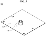
- FIG. 5 is a view illustrating the base plate 500
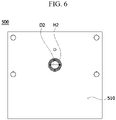
- FIG. 6 is a bottom view of the base plate 500 illustrated in FIG. 5 .
- the base plate 500 may include a body 510 and the first partition 520.
- the substrate 400 is mounted on one surface of the body 510.
- the first partition 520 protrudes from the body 510.
- the first partition 520 is an annular member that forms a space inside.
- the body 510 and the first partition 520 are integrated with each other.
- the bearing 600 is received in an inner side of the first partition 520.
- the first partition 520 forms a second hole H2.
- the second hole H2 is a part penetrated by the shaft 100.
- FIG. 7 is an enlarged view illustrating a part A in FIG. 3 .
- an inner diameter D2 of the second hole H2 is larger than an inner diameter D1 of the first hole H1.
- An inner ring 620 of the bearing 600 is in contact with the shaft 100, and an outer surface of an outer ring 610 of the bearing 600 is in contact with an inner surface of the second hole H2.
- the base plate 500 may include a second partition 530.
- the second partition 530 extends from the first partition 520.
- the second partition 530 may be disposed to be bent from the first partition 520.
- the second partition 530 may be disposed to be overlapped with the first partition 520 in a radial direction x.
- the first partition 520 may be disposed between the bearing 600 and the stator 300.
- An inner surface of the first partition 520 is in contact with a side surface 611 of the outer ring 610 of the bearing 600.
- An outer surface of the first partition 520 is in contact with the stator 300.
- the stator 300 may be fixed to the first partition 520.
- the second partition 530 may be in contact with one surface 612 of the outer ring 610 of the bearing 600.
- an end of the second partition 530 may be in contact with one surface 612 of the outer ring 610 of the bearing 600. Accordingly, the bearing 600 is restrained in the radial direction x by the first partition 520 and is restrained in the axial direction z by the second partition 530.
- FIG. 8 is a side sectional view illustrating a portion of the motor.
- the yoke 210 may include an extension part 213 in contact with the shaft 100.
- the second partition 530 may be disposed to be overlapped with the extension part 213 in the radial direction x.
- at least a portion of the first partition 520 may be disposed to be overlapped with the stator 300 in the radial direction x.
- at least a portion of the first partition 520 may be disposed to be overlapped with the drive magnet 220 and the sensing magnet 230 in the radial direction x.
- a distance L1 from the body 510 to an upper end of the first partition 520 exceeds a length L3 of the bearing 600.
- the distance L1 from the body 510 to the upper end of the first partition 520 is smaller than an axial longest distance L2 of the yoke 210 from the body 510 of the base plate 500.
- a radial distance T1 between an inner surface of the inner ring 620 of the bearing 600 and an outer surface of the outer ring 610 of the bearing 600 may be the same as a difference between the inner diameter D2 of the second hole H2 and the inner diameter D1 of the first hole H1.
- Such a structure is implemented by allowing a portion of the base plate 500 to protrude to the yoke 210 to receive the bearing 600. Since the overall length of the motor is small in the axial direction z, the motor may be easily installed, and high tolerance management of the axial direction z and high structural stability may be achieved. Specifically, since a part that receives the bearing 600 is a portion of the base plate 500 made of iron, there is an advantage of implementing an axial structure with high structural rigidity.
- the first partition 520 may be processed by drawing the base plate 500, which is a flat plate member. Accordingly, a boundary between the first partition 520 and the body 510 may be curved.
- FIG. 9 is a perspective view illustrating the motor according to one embodiment
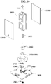
- FIG. 10 is an exploded perspective view of the motor illustrated in FIG. 9
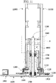
- FIG. 11 is a side sectional view of the motor taken along line A-A in FIG. 9 .
- an inner side is a direction facing the shaft 100 on the basis of the radial direction of the motor
- an outer side is a direction opposite to the inner side.
- the motor may include a shaft 1100, a rotor 1200, and a stator 1300.
- the shaft 1100 is coupled to the yoke 1210 of the rotor 1200.
- the shaft 1100 may be press-fitted and coupled to the yoke 1210.
- the shaft 1100 may be integrated with the yoke 1210.
- the shaft 1100 rotates with the rotor 1200.
- the shaft 1100 is rotatably supported by bearings 1700 disposed in an inner side of a bearing housing 1500.
- the rotor 1200 may include a yoke 1210, a drive magnet 1220, and a sensing magnet 1230.
- the yoke 1210 is coupled to the shaft 1100.
- the shaft 1100 may be disposed at the center of the yoke 1210.
- the drive magnet 1220 is for rotating the yoke 1210.
- the drive magnet 1220 may be disposed on an inner surface of the yoke 1210.
- the drive magnet 1220 may be disposed to face the stator 1300 in the radial direction of the rotor 1200.
- the yoke 1210 rotates.
- the drive magnet 1220 may be a combination of a plurality of unit magnets.
- the drive magnet 1220 may be a single component having a ring shape.
- the sensing magnet 1230 is for precisely recognizing a position of the rotor 1200.
- the sensing magnet 1230 may be disposed on the inner surface of the yoke 1210.
- the sensing magnet 1230 may be disposed to face the substrate 1400 in an axial direction.
- the stator 1300 may be disposed between the shaft 1100 and the yoke 1210.
- the stator 1300 may be fixed to an outer surface of the bearing housing 1500.
- the stator 1300 may include a core of the stator 1300 including a plurality of teeth, and the coil may be wound around each tooth.
- the teeth may include an insulator configured to insulate the coil and the core of the stator 1300.
- the substrate 1400 is disposed on one side of the yoke 1210.
- the substrate 1400 may include a sensor 1410.
- the sensor 1410 may be a Hall IC or an encoder IC that senses a change in magnetic flux of the sensing magnet 1230.
- the sensor 1410 may be disposed to face the drive magnet 1220 or the sensing magnet 1230 in the axial direction.
- the bearing housing 1500 is a member that receives the bearings 1700 inside.
- the bearing housing 1500 may include a region such as a cylindrical member elongated along the axial direction.
- the bearing housing 1500 is fixed to a plate 1600. Although the plate 1600 and the bearing housing 1500 are illustrated separately, the plate 1600 and the bearing housing 1500 may be integrated with each other.
- the substrate 1400 may be seated on one surface of the plate 1600.
- the bearings 1700 may be mounted inside one-side end of the bearing housing 1500 and inside the other-side end thereof, respectively, in an axial direction.
- the bearings 1700 rotatably supports the shaft 1100.
- the bearings 1700 may be disposed not to be overlapped with the stator 1300 in the radial direction of the motor. For example, based on the axial direction, one of two bearings 1700 may be disposed higher than the stator 1300, while the other may be disposed lower than the stator 1300. In addition, one of the two bearings 1700 may be disposed higher than the drive magnet 1220 based on the axial direction.
- a connection member 1800 is a member that couples the yoke 1210 to a holder 1900.
- the connection member 1800 is disposed between the yoke 1210 and the holder 1900 in the axial direction and couples the yoke 1210 to the holder 1900.
- the connection member 1800 may be a cylindrical member.
- One surface of the connection member 1800 may be in contact with the yoke 1210 in the axial direction, and the other surface of the connection member 1800 may be in contact with the holder 1900.
- the holder 1900 fixes mirrors 11000 and 11100.
- the holder 1900 is coupled to the connection member 1800 and rotates together with the yoke 1210.
- the holder 1900 may be a member formed of a frame so that a cross section thereof is hollow inside.
- the holder 1900 having such a shape is resistant to bending and has the advantage of greatly reducing the weight.
- the first mirror 11000 and the second mirror 11100 may be disposed to face each other on one surface and the other surface of the holder 1900.
- the holder 1900 may be disposed to be overlapped with each of the first mirror 11000 and the second mirror 11100 in the radial direction.
- the mirrors 11000 and 11100 serve to reflect a laser irradiated to an object to be sensed.
- the mirrors 11000 and 11100 may include the first mirror 11000 disposed on one surface of the holder 1900 and the second mirror 11100 disposed on the other surface of the holder 1900.
- the yoke 1210 rotates, the holder 1900 rotates, and with the rotation of the holder 1900, the mirrors 11000 and 11100 rotate together.
- the mirrors 11000 and 11100 may be rectangular plate-shaped members which have long axial length.
- the mirrors 11000 and 11100 and the holder 1900 may be coupled to each other via an adhesive.
- FIG. 12 is a perspective view illustrating the connection member 1800
- FIG. 13 is a bottom view of the connection member 1800 illustrated in FIG. 12
- FIG. 14 is a side view of the connection member 1800 illustrated in FIG. 12 .
- the connection member 1800 includes a first surface 1801 and a second surface 1802.
- the first surface 1801 may correspond to one surface of the cylindrical connection member 1800
- the second surface 1802 may correspond to the other surface of the cylindrical connection member 1800.
- the first surface 1801 and the second surface 1802 are disposed to face each other.
- the first surface 1801 and the second surface 1802 each may be disposed on a plane perpendicular to the axial direction.
- the connection member 1800 may include a third hole 1820 and a sixth hole 1810.
- the sixth hole 1810 is a hole penetrated by the shaft 1100.
- An inner diameter of the sixth hole 1810 is disposed larger than an outer diameter of the shaft 1100.
- the sixth hole 1810 is disposed at the center of the connection member 1800.
- the third hole 1820 is a part where a fastening member 11 is fastened.
- the third hole 1820 is disposed by penetrating the first surface 1801 and the second surface 1802.
- a screw tab may be formed on an inner surface of the third hole 1820.
- a plurality of third holes 1820 may be disposed.
- the plurality of third holes 1820 may be disposed at the same interval along the circumferential direction of the connection member 1800.
- the connection member 1800 may include a protrusion 1830.
- the protrusion 1830 protrudes from the second surface 1802.
- the protrusion 1830 may be an annular member.
- the protrusion 1830 is a part that is press-fitted into a first hole 1213a of the yoke 1210.
- a portion of the protrusion 1830 may be disposed to be overlapped with the third hole 1820. This takes into account the positions of a first hole 1213a and a second hole 1213b of the yoke 1210.
- FIG. 15 is an enlarged side view of a part A in FIG. 11 .
- the first surface 1801 of the connection member 1800 is in contact with a lower surface of a third member 1930 of the holder 1900.
- the second surface 1802 of the connection member 1800 is in contact with the upper surface of the yoke 1210.
- the connection member 1800 is disposed between the yoke 1210 and the third member 1930 of the holder 1900 based on the axial direction.
- the fastening member 11 penetrates the third member 1930 of the holder 1900 and is fastened to the third hole 1820 of the connection member 1800. As the fastening member 11 is rotatably fastened to the third hole 1820, the holder 1900 and the connection member 1800 are coupled to each other.
- the protrusion 1830 of the connection member 1800 may be press-fitted into the first hole 1213a of the yoke 1210. As the protrusion 1830 is press-fitted into the first hole 1213a, the connection member 1800 and the yoke 1210 are coupled to each other. As a result, the holder 1900 and the yoke 1210 are coupled via the connection member 1800. Since the holder 1900 is coupled to the yoke 1210 via the connection member 1800, which is a single component, this facilitates assembly.
- the fastening member 11 is disposed to penetrate the connection member 1800 and the third member 1930 of the holder 1900.
- an end of the fastening member 11 may be disposed to penetrate the second hole 1213b of the yoke 1210.
- the end of the fastening member 11 may be disposed such that a portion of the fastening member 11 overlaps the second hole 1213b in the radial direction. Accordingly, the connection member 1800 and the rotor 1200 are restrained to each other by the end of the fastening member 11 in a rotation direction, thereby preventing slip from occurring between the connection member 1800 and the rotor 1200.
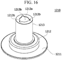
- FIG. 16 is a view illustrating the yoke 1210.
- the yoke 1210 may include a base 1211, a magnet receiving part 1212, and a pillar part 1213.
- the yoke 1210 may be a cylindrical member in which one side and the other side thereof are opened as a whole.
- the magnet receiving part 1212 may protrude from the base 1211.
- the pillar part 1213 may protrude from the magnet receiving part 1212.
- the base 1211, the magnet receiving part 1212 and the pillar part 1213 may have different inner diameters.
- the inner diameter of the base 1211 may be larger than the inner diameter of the magnet receiving part 1212.
- the inner diameter of the magnet receiving part 1212 may be larger than the inner diameter of the pillar part 1213.
- the sensing magnet 1230 is disposed in an inner side of the base 1211.
- the drive magnet 1220 is disposed in an inner side of the magnet receiving part 1212.
- a portion of the bearing housing 1500 may be disposed in an inner side of the pillar part 1213.
- One end surface of the pillar part 1213 is in contact with one end surface of the connection member 1800 in the axial direction.
- the first hole 1213a penetrated by the shaft 1100 may be disposed on one surface of the pillar part 1213.
- the protrusion 1830 of the connection member 1800 is press-fitted into the first hole 1213a.
- the pillar part 1213 may be disposed to be overlapped with the holder 1900 in the radial direction.
- the pillar part 1213 may be disposed to be overlapped with the first mirror 11000 and the second mirror 11100 in the radial direction.
- the shape of the yoke 1210 takes into account characteristics of the shaft 1100, the first mirror 1000, and the second mirror 11100 which are elongated in the axial direction.
- the yoke 1210 may include the second hole 1213b.
- the end of the fastening member 11 is disposed in the second hole 1213b. Since the end of the fastening member 11 is disposed penetrating the second hole 1213b, the yoke 1210 and the connection member 1800 are restrained to each other in the rotation direction.
- a plurality of second holes 1213b may be disposed.
- the number of second holes 1213b may correspond to the number of fastening members 11.
- the second hole 1213b may be concavely formed in the radial direction at an edge of the first hole 1213a.
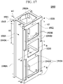
- FIG. 17 is a view illustrating the holder 1900.
- the holder 1900 may include a first member 1910, a second member 1920, a third member 1930, and a sidewall 1950.
- the first member 1910 is coupled to the first mirror 11000.
- the second member 1920 is coupled to the second mirror 11100.
- the third member 1930 connects the first member 1910 and the second member 1920.
- the sidewall 1950 may be disposed between the first member 1910 and the second member 1920.
- the first member 1910 may include a third surface 1901 in contact with the first mirror 11000.
- the second member 1920 may include a fourth surface 1902 in contact with the second mirror 11100.
- the third surface 1901 and the fourth surface 1902 may be disposed to face each other.
- the third surface 1901 and the fourth surface 1902 may be elongated along the axial direction.
- the first surface 1801 may be divided into a horizontal region 1900A and a vertical region 1900B in contact with a partial region of the first mirror 11000.
- the second surface 1802 may also be divided into the horizontal region 1900A and the vertical region 1900B in contact with a partial region of the second mirror 11100.
- the holder 1900 may include a first groove 1940A and a second groove 1940B to which an adhesive is applied.
- the first groove 1940A is concavely formed on the third surface 1901.
- the first groove 1940A may have an axial length k1 greater than a width direction length w1.
- the first groove 1940A may be disposed in the vertical region 1900B of the first surface 1801.
- the second groove 1940B is concavely formed on the fourth surface 1902.
- the second groove 1940B may have the axial length k1 greater than the width direction length w1.
- the second groove 1940B may be disposed in the vertical region 1900B of the second surface 1802.
- the first mirror 11000 and the second mirror 11100 have a rectangular structure with a relatively long axial length in consideration of a scan range. Accordingly, when the first groove 1940A and the second groove 1940B to which the adhesive is applied are elongated in the axial direction, there is an advantage of increasing the coupling force between the first mirror 11000 and the second mirror 11100 and the holder 1900, and there is also an advantage of easily applying the adhesive to the holder 1900 and easily curing the adhesive.
- the holder 1900 may be manufactured by die casting using aluminum which may reduce weight relatively.
- FIG. 18 is a cross-sectional view of the holder taken along line A-Ain FIG. 17 .
- the third member 1930 of the holder 1900 is disposed in a direction perpendicular to the axial direction and connects the first member 1910 and the second member 1920.
- the third member 1930 may include a fourth hole 1960 and a fifth hole 1970.
- the fourth hole 1960 is a part penetrated by the shaft 1100, and an inner diameter of the fourth hole 1960 is set to be larger than an outer diameter of the shaft 1100.
- the shaft 1100 may penetrate the fourth hole 1960, and an end portion of the shaft 1100 may protrude above an upper surface of the third member 1930.
- the fifth hole 1970 is a part penetrated by the fastening member 11, and an inner diameter of the fifth hole 1970 is set to be larger than the outer diameter of the shaft 1100.
- a head of the fastening member 11 may be in contact with the upper surface of the third member 1930.
- the second hole 1213b, the third hole 1820, and the fifth hole 1970 may be disposed to correspond to each other in the axial direction.
- the end of the fastening member 11 that penetrates the fifth hole 1970 and the third hole 1820 are disposed in the second hole 1213b.
- FIG. 19 is a cross-sectional view of the holder 1900 taken along line B-B in FIG. 17 .
- the first member 1910 may include a fifth surface 1903 disposed to face the third surface 1901.
- a third groove 1903a may be disposed on the fifth surface 1903.
- the third groove 1903a may be concavely formed on the fifth surface 1903 towards the third surface 1901 and may be formed as a curved surface.
- the second member 1920 may include a sixth surface 1904 disposed to face the fourth surface 1902.
- a fourth groove 1904a may be disposed on the sixth surface 1904.
- the fourth groove 1904a may be concavely formed on the sixth surface 1904 towards the fourth surface 1902 and may be formed as a curved surface.
- a portion of the yoke 1210 may be disposed in the third groove 1903a.
- another portion of the yoke 1210 may be disposed in the fourth groove 1904a. Due to the third groove 1903a and the fourth groove 1904a, there is an advantage of reducing the size of the holder 1900 while ensuring the size of the yoke 1210.
- FIG. 20 is a perspective view illustrating the motor according to one embodiment
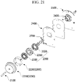
- FIG. 21 is an exploded perspective view of the motor illustrated in FIG. 21
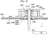
- FIG. 22 is a side sectional view of the motor illustrated in FIG. 21 .
- an inner side is a direction facing the shaft 100 based on the radial direction of the motor
- an outer side is a direction opposite to the inner side.
- the motor may include a shaft 2100, a rotor 2200, a stator 2300, a substrate 2400, a base 2500, a bearing housing 2600, and a bearing 2700.
- the shaft 2100 rotates with the rotor 2200.
- a head of the shaft 2100 may be connected to a sensor device that acquires distance information.
- the rotor 2200 may include a yoke 2210 and a magnet 2220.
- the yoke 2210 is disposed in an outer side of the stator 2300. Furthermore, the yoke 2210 is coupled to the shaft 2100. The shaft 2100 is disposed at the center of the yoke 2210. The shaft 2100 is rotated along with the rotation of the yoke 2210.
- the magnet 2220 may be disposed in the yoke 2210.
- the magnet 2220 is meant to drive the yoke 2210.
- the yoke 2210 rotates via electromagnetic interaction between the magnet 2220 and the coil wound around the stator 2300.
- the magnet 2220 may be one annular member.
- the magnet 2220 may be a combination of a plurality of divided magnets.
- the stator 2300 is disposed in an outer side of the shaft 2100.
- the stator 2300 includes a stator core 2310.
- the stator core 2310 includes a plurality of teeth. The coil winds up in the teeth.
- the stator 2300 may include an insulator 2320.
- the insulator 2320 is coupled to the stator core 2310.
- the substrate 2400 is disposed on one side of the yoke 2210.
- the substrate 2400 may include a sensor 2410 (in FIG. 25 ) and a coil 2420 (in FIG. 25 ).
- the sensor 2410 may be an inductive encoder.
- An air gap is formed between the substrate 2400 and the yoke 2210 in the axial direction.
- the coil 2420 may be a pattern coil.
- the base 2500 is disposed on one side of the substrate 2400.
- the substrate 2400 may be disposed on an upper surface of the base 2500.
- An adhesive film for coupling the base 2500 to the substrate 2400 may be disposed between the base 2500 and the substrate 2400.
- a bearing housing 2600 includes the bearing 2700 inside.
- the bearing 2700 rotatably supports the shaft 2100.
- Two bearings 2700 may be disposed on an upper part and a lower part the bearing housing 2600, respectively.
- the bearing housing 2600 may be coupled to the base 2500. Alternatively, the bearing housing 2600 and the base 2500 may be integrated with each other.
- the bearing housing 2600 may include a first receiving part 2610 and a second receiving part 2620 therein.
- the bearing 2700 is disposed in the first receiving part 2610.
- the bearing 2700 is also disposed in the second receiving part 2620.
- a partition 2630 may be disposed between the first receiving part 2610 and the second receiving part 2620. The partition 2630 protrudes from the inside of the bearing housing 2600 to separate the first receiving part 2610 and the second receiving part 2620, and supports an outer ring of the bearing 2700 in the axial direction.
- the bearing housing 2600 is fixed to the base 2500, and the bearing housing 2600 is coupled to the center of a stator core 2310 of the stator 2300.
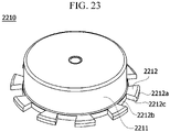
- FIG. 23 is a view illustrating the yoke 2210 of the motor illustrated in FIG. 20 .
- the yoke 2210 includes a cylindrical body 2211 and a flange 2212. One side of the body 2211 is blocked by an upper surface, and the other side of the body 2211 is open.
- the flange 2212 has a shape horizontally extending outwards from one end of the body 2211.
- the shaft 2100 is coupled to an upper surface of the body 2211, and the shaft 2100 and the yoke 2210 are integrally rotated.
- a hole is disposed at the center of the upper surface of the body 2211. An end of the shaft 2100 may be press-fitted and coupled to the hole.
- the magnet 2220 is coupled to an inner circumferential surface of the body 2211. Meanwhile, a thickness t of the body 2211 may be the same as a thickness t of the flange 2212.
- the flange 2212 includes a first edge 2212a, a second edge 2212b, and a third edge 2212c.
- the first edge 2212a and the second edge 2212b are alternately disposed along a circumferential direction of the yoke 2210. In the radial direction of the yoke 2210, the second edge 2212b is disposed closer to the body 2211 than the first edge 2212a.
- the third edge 2212c connects the first edge 2212a and the second edge 2212b.
- the flange 2212 may have a shape with a plurality of blades protruding from the body 2211.
- the flange 2212 interacts with the coil 2420 disposed on the substrate 2400 to generate an induced electromotive force. Since the shape of the flange 2212 changes along the circumferential direction of the yoke 2210, the deviation of the induced electromotive force intermittently appears, and the sensor 2410 senses this phenomenon and uses the same to recognize one rotation of the rotor 2200.
- the flange 2212 may be disposed to be overlapped with the magnet 2220 in the radial direction of the yoke 2210.
- the flange 2212 may be disposed to be overlapped with the bearing housing 2600 in the radial direction of the yoke 2210.
- FIG. 24 is a top plan view of the yoke 2210 illustrated in FIG. 23 .
- the first edge 2212a and the second edge 2212b may be curved surfaces that regard the center C of the yoke 2210 as a center of curvature.
- the second edge 2212b may be disposed on an outer circumferential surface of the body 2211.
- the third edge 2212c may be a plane disposed in the radial direction of the yoke 2210.
- the shape of the flange 2212 of the yoke 2210 is illustrated, the present invention is not limited thereto, and the second edge 2212b may be disposed to protrude rather than the outer circumferential surface of the body 2211.
- the shape of the flange 2212 is a shape where square teeth are repeated, but the present invention is not limited thereto, and the flange 2212 may be implemented with a flange where protruding structures with various shapes are repeated.
- the first edge 2212a and the second edge 2212b may be not curved surfaces but planes, while the third edge 2212c may be disposed to be inclined more than the radial direction of the yoke 2210.
- a plurality of first edges 2212a may have the same circumferential length L12.
- a plurality of second edges 2212b may have the same circumferential length L22 as well.
- the plurality of first edges 2212a may be disposed on one circular orbit on the basis of the center C of the yoke 2210.
- the plurality of second edges 2212b may also be disposed on one circular orbit on the basis of the center C of the yoke 2210.
- the number of the first edge 2212a and the second edge 2212b may be variously controlled to correspond to the resolution of the sensor 2410.
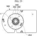
- FIG. 25 is a view illustrating the substrate 2400.
- the sensor 2410 and the coil 2420 are disposed in the substrate 2400.
- the sensor 2410 is electrically connected to the coil 2420 to measure changes in the induced electromotive force according to the rotation of the substrate 2400.
- the coil 2420 may be a combination of a first coil 2421 and a second coil 2422 having different shapes and sizes.
- the first coil 2421 may be radial, and the second coil 2422 may be annular.
- the first coil 2421 and the second coil 2422 are independently separated from each other, and may be disposed on different layers of the substrate 2400.
- the substrate 2400 may have a circular plate shape, and the coil 2420 may be disposed to be symmetrical on the basis of the center of the substrate 2400.
- the coil 2420 may be disposed to be rotationally symmetrical on the basis of the center of the substrate 2400.
- FIG. 26 is a view where the coil and the flange are viewed in the axial direction.
- the coil 2420 is disposed to face the flange 2212.
- a portion of the coil 2420 may be disposed between the first edge 2212a and the second edge 2212b of the flange 2212 based on the radial direction of the yoke 2210.
- the first edge 2212a may be disposed in an outer side of the coil 2420.
- the rotor 2300 rotates by electrical interaction between a coil wound around the stator core 2310 and the magnet 2220, magnetic induction occurs between the coil 2420 and the flange 2212 of the yoke 2210 by the shape of the flange 2212 of the rotor 2200, and the sensor 2410 senses a change in the magnetic induction.
- the configuration of the motor may be greatly simplified by utilizing the flange 2212 as a portion of the yoke 2210 and the coil 2420.
- an advantage here is that there is no magnetic field interference with the drive magnet.
- an advantage here is that the electromotive force generated by the coil 2420 of the substrate 2400 can greatly reduce interference of external magnetic field.
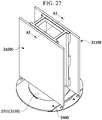
- FIG. 27 is a perspective view illustrating the motor according to one embodiment
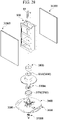
- FIG. 28 is an exploded perspective view of the motor illustrated in FIG. 27
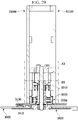
- FIG. 29 is a side sectional view of the motor taken along line A3-A3 in FIG. 27 .
- an inner side is a direction facing a shaft 3100 based on the radial direction of the motor
- an outer side is a direction opposite to the inner side.
- the motor may include the shaft 3100, a rotor 3200, and a stator 3300.
- the shaft 3100 is coupled to a yoke 3210 of the rotor 3200.
- the shaft 3100 may be press-fitted and coupled to the yoke 3210. Alternatively, the shaft 3100 may be integrated with the yoke 3210.
- the shaft 3100 rotates with the rotor 3200.
- the shaft 3100 is rotatably supported by a bearing 3700 disposed in an inner side of a bearing housing 3500.
- the rotor 3200 may include the yoke 3210, a drive magnet 3220, and a sensing magnet 3230.
- the yoke 3210 is coupled to the shaft 3100.
- the shaft 3100 may be disposed at the center of the yoke 3210.
- the drive magnet 3220 is meant to rotate the yoke 3210.
- the drive magnet 3220 may be disposed on an inner surface of the yoke 3210.
- the drive magnet 3220 may be disposed to face the stator 3300 in the radial direction of the rotor 3200.
- the yoke 3210 rotates.
- the drive magnet 3220 may be a combination of a plurality of unit magnets.
- the drive magnet 3220 may be a single component with a ring shape.
- the sensing magnet 3230 is meant to precisely recognize a position of the rotor 3200.
- the sensing magnet 3230 may be disposed on the inner surface of the yoke 3210.
- the sensing magnet 3230 may be disposed to face the substrate 3400 in an axial direction.
- the stator 3300 may be disposed between the shaft 3100 and the yoke 3210.
- the stator 3300 may be fixed to an outer surface of the bearing housing 3500.
- the stator 3300 includes a core of the stator including a plurality of teeth, and the coil may be wound around each tooth.
- the teeth may include an insulator configured to insulate the coil and the core of stator.
- the substrate 3400 is disposed on one side of the yoke 3210.
- the substrate 3400 may include a sensor 3410.
- the sensor 3410 may be a Hall IC or an encoder IC that senses a change in a magnetic flux of the sensing magnet 3230.
- the sensor 3410 may be disposed to face the drive magnet 3220 or the sensing magnet 3230 in the axial direction.
- the bearing housing 3500 is a member that fixes a first bearing 3700A and a second bearing 3700B to form an axial system.
- the bearing housing 3500 may include a region such as a cylindrical member elongated along the axial direction.
- a bearing housing 3500 is fixed to a plate 3600. Although the plate 3600 and the bearing housing 3500 are illustrated separately, the plate 3600 and the bearing housing 3500 may be integrated with each other.
- the substrate 3400 may be mounted on one surface of the plate 3600.
- the first bearing 3700A may be disposed in an outer side of the bearing housing 3500.
- the first bearing 3700A rotatably supports the yoke 3210.
- the second bearing 3700B may be disposed in an inner side of the bearing housing 3500.
- the second bearing 3700B rotatably supports the shaft 3100.
- Each of the first bearing 3700A and the second bearing 3700B may be disposed not to be overlapped with the stator 3300 in the radial direction of the motor. For example, based on the axial direction, the first bearing 3700A may be disposed higher than the stator 3300, and the second bearing 3700B may be disposed lower than the stator 3300. In addition, the first bearing 3700A may be disposed higher than the drive magnet 3220 based on the axial direction.
- a connection member 3800 is a member that couples the yoke 3210 to the holder 3900.
- the connection member 3800 is disposed between the yoke 3210 and the holder 3900 in the axial direction and couples the yoke 3210 to the holder 3900.
- the connection member 3800 may be a cylindrical member.
- One surface of the connection member 3800 may be in contact with the yoke 3210 in the axial direction, and the other surface of the connection member 3800 may be in contact with the holder 3900.
- the holder 3900 fixes the mirrors 31000 and 31100.
- the holder 3900 is coupled to the connection member 3800 and rotates with the yoke 3210.
- the holder 3900 may be a member formed of a frame such that a cross section thereof is hollow inside.
- the holder 3900 having such a shape is resistant to bending and has the advantage of greatly reducing the weight.
- the first mirror 31000 and the second mirror 31100 may be disposed to face each other on one surface and the other surface of the holder 3900.
- the holder 3900 may be disposed to be overlapped with each of the first mirror 31000 and the second mirror 31100 in the radial direction.
- the mirrors 31000 and 31100 serve to reflect a laser irradiated to an object to be sensed.
- the mirrors 31000 and 31100 may include the first mirror 31000 disposed on one surface of the holder 3900 and the second mirror 31100 disposed on the other surface of the holder 3900.
- the mirrors 31000 and 31100 may be rectangular plate-shaped members which have a long axial length.
- the mirrors 31000 and 31100 and the holder 3900 may be coupled to each other via the adhesive.
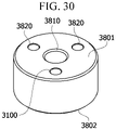
- FIG. 30 is a perspective view illustrating the connection member 3800
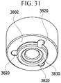
- FIG. 31 is a bottom view of the connection member 3800 illustrated in FIG. 30
- FIG. 32 is a side view of the connection member 3800 illustrated in FIG. 30 .
- the connection member 3800 includes a first surface 3801 and a second surface 3802.
- the first surface 3801 may correspond to one surface of the cylindrical connection member 3800
- the second surface 3802 may correspond to the other surface of the cylindrical connection member 3800.
- the first surface 3801 and the second surface 3802 are disposed to face each other.
- Each of the first surface 3801 and the second surface 3802 may be disposed on a plane perpendicular to the axial direction.
- the connection member 3800 may include a third hole 3820 and a sixth hole 3810.
- the sixth hole 3810 is a hole penetrated by the shaft 3100.
- An inner diameter of the sixth hole 3810 is disposed larger than an outer diameter of the shaft 3100.
- the sixth hole 3810 is disposed at the center of the connection member 3800.
- the third hole 3820 is a part where a fastening member 13 is fastened.
- the third hole 3820 is disposed by penetrating the first surface 3801 and the second surface 3802.
- a screw tab may be formed on an inner surface of the third hole 3820.
- a plurality of third holes 3820 may be disposed.
- the plurality of third holes 3820 may be disposed at the same interval along the circumferential direction of the connection member 3800.
- the connection member 3800 may include a protrusion 3830.
- the protrusion 3830 protrudes from the second surface 3802.
- the protrusion 3830 may be an annular member.
- the protrusion 3830 is a part that is press-fitted into a first hole 3213a of the yoke 3210.
- a portion of the protrusion 3830 may be disposed to be overlapped with the third hole 3820. This takes into account the positions of a first hole 3213a and a second hole 3213b of the yoke 3210.
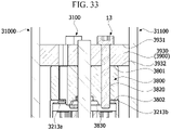
- FIG. 33 is an enlarged side view of a part A3 in FIG. 29 .
- the first surface 3801 of the connection member 3800 is in contact with a lower surface of a third member 3930 of the holder 3900.
- the second surface 3802 of the connection member 3800 is in contact with the upper surface of the yoke 3210.
- the connection member 3800 is disposed between the yoke 3210 and the third member 3930 of the holder 3900 based on the axial direction.
- the fastening member 13 penetrates the third member 3930 of the holder 3900 and is fastened to the third hole 3820 of the connection member 3800. As the fastening member 13 is rotatably fastened to the third hole 3820, the holder 3900 and the connection member 3800 are coupled to each other.
- the protrusion 3830 of the connection member 3800 may be press-fitted into the first hole 3213a of the yoke 3210. As the protrusion 3830 is press-fitted into the first hole 3213a, the connection member 3800 and the yoke 3210 are coupled to each other. As a result, the holder 3900 and the yoke 3210 are coupled via the connection member 3800. Since the holder 3900 is coupled to the yoke 3210 via the connection member 3800, which is a single component, this facilitates assembly.
- the fastening member 13 is disposed to penetrate the connection member 3800 and the third member 3930 of the holder 3900.
- an end of the fastening member 13 may be disposed to penetrate the second hole 3213b of the yoke 3210.
- the end of the fastening member 13 may be disposed such that a portion of the fastening member 13 overlaps the second hole 3213b in the radial direction. Accordingly, the connection member 3800 and the rotor 3200 are restrained to each other by the end of the fastening member 13 in the rotation direction, thereby preventing slip from occurring between the connection member 3800 and the rotor 3200.
- FIG. 34 is a view illustrating the yoke 3210.
- the yoke 3210 may include a base 3211, a magnet receiving part 3212 and a pillar part 3213.
- the yoke 3210 may be a cylindrical member in which one side and the other side thereof are opened as a whole.
- the magnet receiving part 3212 may protrude from the base 3211.
- the pillar part 3213 may protrude from the magnet receiving part 3212.
- the base 3211, the magnet receiving part 3212 and the pillar part 3213 may have different inner diameters.
- the inner diameter of the base 3211 may be larger than the inner diameter of the magnet receiving part 3212.
- the inner diameter of the magnet receiving part 3212 may be larger than the inner diameter of the pillar part 3213.
- the sensing magnet 3230 is disposed in an inner side of the base 3211.
- the drive magnet 3220 is disposed in an inner side of the magnet receiving part 3212.
- a portion of the bearing housing 3500 may be disposed in an inner side of the pillar part 3213.
- One end surface of the pillar part 3213 is in contact with one end surface of the connection member 3800 in the axial direction.
- the first hole 3213a penetrated by the shaft 3100 may be disposed on one surface of the pillar part 3213.
- the protrusion 3830 of the connection member 3800 is press-fitted into the first hole 3213a.
- the pillar part 3213 may be disposed to be overlapped with the holder 3900 in the radial direction.
- the pillar part 3213 may be disposed to be overlapped with the first mirror 31000 and the second mirror 31100 in the radial direction.
- the shape of the yoke 3210 takes into account the characteristics of the shaft 3100, the first mirror 31000, and the second mirror 31100 which are elongated in the axial direction.
- the yoke 3210 may include the second hole 3213b.
- the end of the fastening member 13 is positioned in the second hole 3213b. Since the end of the fastening member 13 is disposed penetrating the second hole 3213b, the yoke 3210 and the connection member 3800 are restrained to each other in the rotational direction.
- a plurality of second holes 3213b may be disposed.
- the number of second holes 3213b may correspond to the number of fastening members 13.
- the second hole 3213b may be concavely formed in the radial direction at an edge of the first hole 3213a.
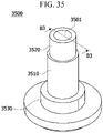
- FIG. 35 is a perspective view illustrating the bearing housing 3500
- FIG. 36 is a side sectional view of the bearing housing 3500 taken along line B3-B3 in FIG. 35 .
- the bearing housing 3500 may include a first region 3510 in contact with the stator 3300, a second region 3520 in contact with the first bearing 3700A, and a third region 3530 in contact with the second bearing 3700B.
- the first region 3510 is disposed in one side of the second region 3520 in the axial direction, and the third region 3530 is disposed in the other side of the first region 3510.
- a hole 3501 is disposed at the center of the bearing housing 3500.
- the shaft 3100 is disposed in an inner side of the hole 3501.
- the bearing housing 3500 may include a receiving space S that receives the second bearing 3700B. The hole 3501 and the receiving space S communicate with each other.
- An outer diameter D13 of the first region 3510 may be larger than an outer diameter D23 of the second region 3520.
- an inner diameter D33 of the third region 3530 may be larger than an outer diameter D13 of the first region 3510.
- the structure of the bearing housing 3500 is meant to increase the axial length of the mirrors 31000 and 31100 by arranging the stator 3300 to be overlapped with the mirrors 31000 and 31100 in the radial direction.
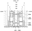
- FIG. 37 it is an enlarged side view of a part B3 in FIG. 29 .
- the motor according to one embodiment has the advantage of enhancing the sensing performance by increasing the axial length of the mirrors 31000 and 31100.
- the outer diameter of the stator 3300 needs to be reduced such that the stator 3300 is disposed in the inner side of the mirrors 31000 and 31100.
- a winding space of the coil for securing a torque decreases. Accordingly, the inner diameter of the stator 3300 is reduced to sufficiently secure the winding space of the coil.
- the outer diameter of the bearing housing 3500 When reducing the inner diameter of the stator 3300, the outer diameter of the bearing housing 3500 also decreases, and accordingly, the bearing installation space disposed between the inner surface of the bearing housing 3500 and the shaft 3100 is narrowed, so it becomes difficult to install the bearing.
- the first bearing 3700A is disposed between the bearing housing 3500 and the yoke so as to solve this problem.
- the first bearing 3700A is disposed in the outer side of the bearing housing 3500, the bearing with a relatively large size may be installed. Therefore, robustness of the axial structure can be greatly improved.
- the second bearing 3700B supports the shaft 3100 and the first bearing 3700A directly supports the yoke 3210, the robustness of the axial structure may be further improved.
- the first bearing 3700A is disposed to overlap the mirrors 31000 and 31100 in the radial direction.
- the second bearing 3700B is disposed not to overlap the mirrors 31000 and 31100 in the radial direction.
- An inner diameter D93 of the first bearing 3700A is larger than an inner diameter D83 of the second bearing 3700B. This is because an inner ring of the first bearing 3700Ais fixed to the bearing housing 3500, and an inner ring of the second bearing 3700B is fixed to the shaft.
- the magnet receiving part 3212 is disposed to overlap the mirrors 31000 and 31100 in the radial direction.
- An outer diameter D43 of the magnet receiving part 3212 is larger than an outer diameter D53 of the pillar part 3213.
- the outer diameter D43 of the magnet receiving part 3212 is smaller than the shortest distance L between the first mirror 31000 and the second mirror 31100.
- An inner diameter D73 of the stator 3300 is smaller than an outer diameter D63 of the first bearing 3700A. This is meant for the stator 3300 to be positioned between the first mirror 31000 and the second mirror 31100.
- the drive magnet 3220 of the rotor 3200 is disposed to be overlapped with the first mirror 31000 and the second mirror 31100 in the radial direction.
- FIG. 38 is a view illustrating the holder 3900.
- the holder 3900 may include a first member 3910, a second member 3920, a third member 3930, and a sidewall 3950.
- the first member 3910 is coupled to the first mirror 31000.
- the second member 3920 is coupled to the second mirror 31100.
- the third member 3930 connects the first member 3910 and the second member 3920.
- the sidewall 3950 may be disposed between the first member 3910 and the second member 3920.
- the first member 3910 may include a third surface 3901 in contact with the first mirror 31000.
- the second member 3920 may include a fourth surface 3902 in contact with the second mirror 31100.
- the third surface 3901 and the fourth surface 3902 may be disposed to face each other.
- the third surface 3901 and the fourth surface 3902 may be elongated along the axial direction.
- the first surface 3801 may be divided into a horizontal area 3900A and a vertical area 3900B in contact with a partial region of the first mirror 31000.
- the second surface 3802 may also be divided into the horizontal area 3900A and the vertical area 3900B in contact with a partial region of the second mirror 31100.
- the holder 3900 may include a first groove 3940A and a second groove 3940B to which an adhesive is applied.
- the first groove 3940A is concavely formed on the third surface 3901.
- the first groove 3940A may have an axial length k13 greater than the width direction length w13.
- the first groove 3940A may be disposed in the vertical region 3900B of the first surface 3801.
- the second groove 3940B is concavely formed on the fourth surface 3902.
- the second groove 3940B may have the axial length k13 greater than the width direction length w13.
- the second groove 3940B may be disposed in the vertical region 3900B of the second surface 3802.
- the first mirror 31000 and the second mirror 31100 have a rectangular structure with a relatively long axial length in consideration of a scan range. Accordingly, when the first groove 3940A and the second groove 3940B to which the adhesive is applied are elongated in the axial direction, there is an advantage of increasing the coupling force between the first mirror 31000 and the second mirror 31100 and the holder 3900, and there is also an advantage of easily applying the adhesive to the holder 3900 and easily curing the adhesive.
- the holder 3900 may be manufactured by the die casting using aluminum which may reduce weight relatively.
- FIG. 39 is a cross-sectional view of the holder 3900 taken along line C3-C3 in FIG. 38 .
- the third member 3930 of the holder 3900 is disposed in a direction perpendicular to the axial direction and connects the first member 3910 and the second member 3920.
- the third member 3930 may include a fourth hole 3960 and a fifth hole 3970.
- the fourth hole 3960 is a part penetrated by the shaft 3100, and an inner diameter of the fourth hole 3960 is set to be larger than an outer diameter of the shaft 3100.
- the shaft 3100 may penetrate the fourth hole 3960, and an end of the shaft 3100 may protrude above the upper surface of the third member 3930.
- the fifth hole 3970 is a part penetrated by the fastening member 13, and an inner diameter of the fifth hole 3970 is set to be larger than the outer diameter of the shaft 3100.
- a head of the fastening member 13 may be in contact with the upper surface of the third member 3930.
- the second hole 3213b, the third hole 3820, and the fifth hole 3970 may be disposed to correspond to the axial direction.
- the end of the fastening member 13 that penetrates the fifth hole 3970 and the third hole 3820 are disposed in the second hole 3213b.
- FIG. 40 is a cross-sectional view of the holder 3900 taken along line D3-D3 in FIG. 38 .
- the first member 3910 may include a fifth surface 3903 disposed to face the third surface 3901.
- a third groove 3903a may be disposed on the fifth surface 3903.
- the third groove 3903a may be concavely formed on the fifth surface 3903 towards the third surface 3901 and may be formed as a curved surface.
- the second member 3920 may include a sixth surface 3904 disposed to face the fourth surface 3902.
- a fourth groove 3904a may be disposed on the sixth surface 3904.
- the fourth groove 3904a may be concavely formed on the sixth surface 3904 towards the fourth surface 3902 and may be formed as a curved surface.
- a portion of the yoke 3210 may be disposed in the third groove 3903a.
- another portion of the yoke 3210 may be disposed in the fourth groove 3904a. Due to the third groove 3903a and the fourth groove 3904a, there is an advantage of reducing the size of the holder 3900 while securing the size of the yoke 3210.
- FIG. 41 is a perspective view illustrating the motor according to one embodiment
- FIG. 42 is an exploded perspective view of the motor illustrated in FIG. 41
- FIG. 43 is a side sectional view of the motor taken along line A4-A4 in FIG. 41 .
- an inner side is a direction facing the shaft 4100 based on the radial direction of the motor
- an outer side is a direction opposite to the inner side.
- the motor may include a shaft 4100, a rotor 4200, and a stator 4300.
- the shaft 4100 is coupled to a yoke 4210 of the rotor 4200.
- the shaft 4100 may be press-fitted and coupled to the yoke 4210. Alternatively, the shaft 4100 may be integrated with the yoke 4210.
- the shaft 4100 rotates with the rotor 4200.
- the shaft 4100 is rotatably supported by a bearing 4700 disposed in an inner side of the bearing housing 4500.
- the rotor 4200 may include a yoke 4210, a drive magnet 4220, and a sensing magnet 4230.
- the yoke 4210 is coupled to the shaft 4100.
- the shaft 4100 may be disposed at the center of the yoke 4210.
- the drive magnet 4220 is meant to rotate the yoke 4210.
- the drive magnet 4220 may be disposed on an inner surface of the yoke 4210.
- the drive magnet 4220 may be disposed to face the stator 4300 in the radial direction of the rotor 4200.
- the yoke 4210 rotates.
- the drive magnet 4220 may be a combination of a plurality of unit magnets.
- the drive magnet 4220 may be a single component with a ring shape.
- the sensing magnet 4230 is meant to precisely recognize a position of the rotor 4200.
- the sensing magnet 4230 may be disposed on the inner surface of the yoke 4210.
- the sensing magnet 4230 may be disposed to face the substrate 4400 in the axial direction.
- the stator 4300 may be disposed between the shaft 4100 and the yoke 4210.
- the stator 4300 may be fixed to an outer surface of the bearing housing 4500.
- the stator 4300 includes a core of the stator 4300 including a plurality of teeth, and the coil may be wound around each tooth.
- the teeth may include an insulator configured to insulate the coil and the core of the stator 4300.
- the substrate 4400 is disposed on one side of the yoke 4210.
- the substrate 4400 may include a first sensor 4410.
- the first sensor 4410 may be a Hall IC or an encoder IC that senses a change in a magnetic flux of the sensing magnet 4230.
- the first sensor 4410 may be disposed to face the sensing magnet 4230 in the axial direction.
- the substrate 4400 may include a second sensor 4420.
- the second sensor 4420 may be a Hall IC that senses a change in a magnetic flux of the drive magnet 4220.
- the second sensor 4420 may be disposed to face the drive magnet 4220 in the axial direction.
- the bearing housing 4500 is a member that fixes a first bearing 4700A and a second bearing 4700B to form an axial system.
- the bearing housing 4500 may include a region such as a cylindrical member elongated along the axial direction.
- the bearing housing 4500 is fixed to a plate 4600. Although the plate 4600 and the bearing housing 4500 are illustrated separately, the plate 4600 and the bearing housing 4500 may be integrated with each other.
- the substrate 4400 may be mounted on one surface of the plate 4600.
- the first bearing 4700A may support an upper end of the shaft 4100, and the second bearing 4700B may support a lower end of the shaft 4100.
- the connection member 4800 is a member that couples the yoke 4210 to a holder 4900.
- the connection member 4800 is disposed between the yoke 4210 and the holder 4900 in the axial direction and couples the yoke 4210 to the holder 4900.
- the connection member 4800 may be a cylindrical member.
- One surface of the connection member 4800 may be in contact with the yoke 4210 in the axial direction, and the other surface of the connection member 4800 may be in contact with the holder 4900.
- the holder 4900 fixes the mirror 41000.
- the holder 4900 is coupled to the connection member 4800 and rotates with the yoke 4210.
- the holder 4900 may be a member formed of a frame such that cross section thereof is hollow inside.
- the holder 4900 having such a shape is resistant to bending and has the advantage of greatly reducing the weight.
- the first mirror 41000A and the second mirror 41000B may be disposed to face each other on one surface and the other surface of the holder 4900.
- the holder 4900 may be disposed to be overlapped with each of the first mirror 41000A and the second mirror 41000B in the radial direction.
- the mirror 41000 serves to reflect a laser irradiated to an object to be sensed.
- the mirror 41000 may include the first mirror 41000A disposed on one surface of the holder 4900 and the second mirror 41100B disposed on the other surface of the holder 4900.
- the yoke 4210 rotates, the holder 4900 rotates, and with the rotation of the holder 4900, the mirror 41000 rotates together.
- FIG. 44 is a perspective view illustrating the mirror
- FIG. 45 is a top plan view of the mirror illustrated in FIG. 44 .
- the mirror 41000 may be a rectangular plate-shaped member which has a long axial length.
- the mirror 41000 may include a rear surface 41100, a side surface 41200, a front surface 41300, an upper surface 41400, and a lower surface 41500.
- the rear surface 41100 is a surface in contact with the holder 4900.
- the front surface 41300 is a surface that reflects a laser.
- the side surfaces 41200 may be disposed on one side and the other side of the mirror 41000, respectively.
- the side surface 41200 may include a first side surface 41210 and a second side surface 41220.
- the first side surface 41210 may be a surface adjacent disposed to the front surface 41300, and the second side surface 41220 may be a surface disposed adjacent to the rear surface 41100.
- the first side surface 41210 may be disposed to be inclined with regard to a surface extending from the front surface 41300. Accordingly, a region of the front surface 41300 may be smaller than that of the rear surface 41100.
- FIG. 46 is a perspective view illustrating a body of the holder 4900.
- the holder 4900 may include a body 4910.
- the body 4910 includes a first surface 4901 in contact with the rear surface 41100 of the mirror 41000.
- Two first surfaces 4901 may be disposed to face each other, and the two first surfaces 4901 may be connected to two side parts 4910A disposed to be spaced apart from each other.
- a fastening hole 4904 may be disposed in each of the side parts 4910A. The fastening hole 4904 is for coupling the holder 4900 to the bracket 4920.
- FIG. 47 is a perspective view illustrating a bracket 4920 of the holder 4900
- FIG. 48 is a top plan view of the bracket 4920 illustrated in FIG. 47 .
- the bracket 4920 is a member that fixes the mirror 41000 and the body 4910 of the holder 4900.
- the bracket 4920 may include a bracket body 4921 and a clip part 4922.
- the bracket body 4921 is fixed to a side part 4910A of the holder 4900.
- the cross-sectional shape of the bracket body 4921 may be a " ⁇ " type.
- a fastening hole 4921a is formed in the bracket body 4921.
- the bracket body 4921 is coupled to the body 4910 of the holder 4900 via a first screw 24 or a second skew 34 that penetrate the fastening hole 4921a.
- the clip part 4922 may be bent outwards from an end part of the bracket body 4921.
- the clip part 4922 is an elastically deformable member, which is a part that directly fixes the mirror 41000 by pressing the side surface 41200 of the mirror 41000.
- the clip part 4922 may be divided into a first region 4922a and a second region 4922b.
- the first region 4922a is a part vertically bent from the bracket body 4921.
- the second region 4922b is a part bent towards the bracket body 4921 in the first region 4922a.
- the holder 4900 includes a first protrusion 4902 that is in contact with the mirror 41000 and fixes the mirror 41000 to the holder 4900.
- the first protrusion 4902 is formed to protrude rather than the first surface 4901.
- a surface indicative of the extending surface of the first surface 4901 is a reference surface L40, and in the bracket 4920, the second region 4922b protruding rather than the reference surface L40 corresponds to a first protrusion portion 4902.
- FIG. 49 is a top plan view of the holder 4900 and the mirror 41000.
- the second region 4922b of the bracket 4920 is in contact with the side surface 41200 of the mirror 41000 and fixes the mirror 41000 to the holder 4900. Specifically, the second region 4922b presses the mirror 41000 by contacting the inclined first side surface 41210 of the mirror 41000. Since the second region 4922b is inclined to correspond to the first side surface 41210, the fixing force may be increased by pressing the mirror 41000 in a direction towards the holder 4900.
- a pad in contact with the first side surface 41210 is attached to the second region 4922b, thereby preventing scratching and damaging the first surface 41210 and causing vibration, noise or separation due to the gap between the second region 4922b and the first side surface 41210.
- FIG. 50 is a view illustrating a process of assembling the holder 4900 and the mirror 41000.
- the mirror 41000 is primarily fixed to the body 4910 of the holder 4900 using the adhesive.
- the bracket 4920 is mounted in the body 4910 of the holder 4900 as illustrated in (c) and (d) of FIGS. 50
- the clip part 4922 of the bracket 4920 presses the side surface 41200 of the mirror 41000 to additionally fix the mirror 41000 to the body 4910.
- the bracket 4920 is fastened to the body 4910 of the holder 4900 via the first screw 24 and the second skew 34, the mirror 41000 is finally fixed to the holder 4900.
- FIG. 51 is a view illustrating the body 4910 of the holder 4900 according to one modified embodiment
- FIG. 52 is a side view of the holder 4900 according to another modified embodiment
- FIG. 53 is a side view illustrating the mirror 41000 and the holder 4900 in which the body 4910 illustrated in FIG. 51 is disposed.
- a second protrusion 4905 may be disposed on the body 4910 of the holder 4900.
- the second protrusion 4905 protrudes rather than the first surface 4901 and is in contact with the upper surface 41400 or the lower surface 41500 of the mirror 41000.
- the second protrusion 4905 supports the upper surface 41400 and the lower surface 41500 of the mirror 41000, thereby more firmly fixing the mirror 41000 to the holder 4900 and preventing the mirror 41000 from being separated to an upper side or a lower side of the holder 4900.
- a height H14 of the mirror 41000 may exceed a height H24 of the bracket 4920 and less than a height H34 of the holder 4900.
- FIG. 54 is a view illustrating the holder 4900 and the mirror 41000 according to further another modified embodiment
- FIG. 55 is a perspective view of the bracket 4920 illustrated in FIG. 54
- FIG. 56 is a top plan view of the bracket 4920 illustrated in FIG. 54 .
- the holder 4900 and the mirror 41000 are characterized in that the holder 4900 is in contact with the front surface 41300 of the mirror 41000 to fix the mirror 41000.
- the clip part 4922 of the bracket 4920 of the holder 4900 may include a third region 4922c and a fourth region 4922d.
- the third region 4922c may be vertically bent at the bracket body 4921.
- the fourth region 4922d may be vertically bent to the bracket body 4921 in the third region 4922c.
- the fourth region 4922d is in contact with a front surface 41300 of the mirror 41000.
- the length of the fourth region 4922d may be formed relatively much shorter than the length of the third region 4922c. This is meant to minimize the front surface 41300 of the mirror 41000.
- FIG. 57 is a top plan view illustrating the bracket 4920 that is in contact with the front surface 41300 of the mirror 41000 and fixes the mirror 41000 to the holder 4900.
- the fourth region 4922d of the clip part 4922 of the bracket 4920 may be in contact with the vicinity of an edge of the front surface 41300 of the mirror 41000 and fix the mirror 41000 to the body 4910 of the holder 4900. Since the bracket 4920 is in contact with and fixes the front surface 41300 of the mirror 41000, the mirror 41000 may be more firmly fixed to the holder 4900 than when the bracket 4920 fixes the side surface 41200 of the mirror 41000. Since the fourth region 4922d fixes only a small portion of the front surface 41300 of the mirror 41000 and the height of the bracket 4920 is relatively very small than the height of the mirror 41000, the mirror 41000 may be fixed to the holder 4900 without significantly affecting sensing performance.
- FIG. 58 is a view illustrating the holder 4900 and the mirror 41000 according to still further another modified embodiment
- FIG. 59 is an exploded view of the holder 4900 and the mirror 41000 illustrated in FIG. 58
- FIG. 60 is a top plan view of the holder 4900 and the mirror 41000.
- the holder 4900 may be implemented as a first protrusion part 4902 where a portion of the body 4910 supports the side surface 41200 of the mirror 41000.
- the body 4910 may include a first part 4911 and a second part 4912.
- the first part 4911 and the second part 4912 are coupled to each other by the first screw 24 and the second screw 34.
- the first part 4911 and the second part 4912 may have the same shape and size.
- Each of the first part 4911 and the second part 4912 may have a cross-sectional shape formed in a " ⁇ " type.
- the first part 4911 and the second part 4912 may be disposed symmetrically on the basis of a width center C of the mirror 41000.
- the first part 4911 may include a portion of the first surface 4901 in contact with the rear surface 41100 of the mirror 41000.
- the second part 4912 may include the remainder of the first surface 4901 in contact with the rear surface 41100 of the mirror 41000.
- the first protrusion 4902 may include a first-first protrusion 4902A in contact with one side surface 41200 of the mirror 41000 and a first-second protrusion 4902B in contact with the other side surface 41200 of the mirror 41000.
- the first-first protrusion 4902A is disposed to protrude from an end of the first part 4911 rather than the first surface 4901.
- the first-second protrusion portion 4902B is disposed to protrude from an end of the second part 4912 rather than the first surface 4901.
- a thickness t14 of the first protrusion 4902 may be the same as a thickness t24 of the mirror 41000.
- the first screw 24 may be fastened by penetrating the first part 4911 and the second part 4912 at the side of the first part 4911. Accordingly, a head of the first screw 24 is in contact with the first part 4911.
- the second screw 34 may be fastened by penetrating the first part 4911 and the second part 4912 at the side of the second part 4912. Accordingly, a head of the second screw 34 is in contact with the second part 4912.
- FIG. 61 is a view illustrating the holder 4900 and the mirror 41000 according to still further another modified embodiment
- FIG. 62 is an exploded view of the holder 4900 and the mirror 41000 illustrated in FIG. 61
- FIG. 63 is a top plan view of the holder 4900 and the mirror 41000.
- a portion of the body 4910 is implemented as a first protrusion 4902 that supports the side surface 41200 of the mirror 41000; however, the body 4910 is made up of three parts, and the side surface 41200 of the mirror 41000 is disposed in a stepped manner.
- the body 4910 may include a third part 4913, a fourth part 4914, and a fifth part 4915.
- the third part 4913 may have a hexahedral block shape including the first surface 4901.
- the fourth part 4914 and the fifth part 4915 are coupled to the third part 4913 via the first screw 24 and the second screw 34, respectively.
- Each of the fourth part 4914 and the fifth part 4915 may have a cross-sectional shape formed in a " ⁇ " type.
- the first protrusions 4902 may be disposed on the fourth part 4914 and the fifth part 4915, respectively.
- the side surface 41200 of the mirror 41000 may include a third side surface 41200 disposed adjacent to the front surface 41300 of the mirror 41000 and a fourth side surface 41200 disposed adjacent to the rear surface 41100 of the mirror 41000.
- the third side surface 41200 and the fourth side surface 41200 are connected to each other using a stepped surface 1250.
- the first protrusion 4902 may be disposed to be in contact with the stepped surface 1250. That is, a portion of the mirror 41000 and a portion of the first protrusion 4902 are disposed to overlap each other based on a thickness direction of the mirror 41000.
- the structure of the side surface 41200 of the mirror 41000 and the first protrusion 4902 has the advantage of increasing the coupling force between the mirror 41000 and the holder 4900. In particular, the mirror 41000 may be prevented from being separated in the radial direction of the motor by centrifugal force.
- the present invention may be used in a variety of devices such as vehicles or home appliances.
Landscapes
- Engineering & Computer Science (AREA)
- Power Engineering (AREA)
- Physics & Mathematics (AREA)
- General Physics & Mathematics (AREA)
- Electromagnetism (AREA)
- Computer Networks & Wireless Communication (AREA)
- Radar, Positioning & Navigation (AREA)
- Remote Sensing (AREA)
- Microelectronics & Electronic Packaging (AREA)
- Motor Or Generator Frames (AREA)
- Mechanical Optical Scanning Systems (AREA)
Abstract
Description
- Embodiments relate to a motor.
- A motor may include a rotor, a stator and a shaft. The shaft is coupled to the rotor. The rotor may be disposed outside of the stator. The rotor rotates via the electromagnetic interaction between the rotor and the stator, and when the rotor rotates, the shaft rotates.
- The shaft may connect a sensor device (e.g., light detection and ranging (LiDAR)).
- In order to detect a position of the rotor, the motor may include a sensor configured to sense a change in a magnetic flux of a drive magnet disposed in the rotor. In addition, a separate sensing magnet which is multi-polar magnetized may be disposed to increase resolution and a sensor configured to sense the change in the magnetic flux therefrom may be provided.
- These sensors may be mounted on a substrate. The substrate may be mounted on a base plate. Meanwhile, a bearing configured to support the shaft may be provided, and the bearing may be received in a bearing housing. The bearing housing may be coupled to the base plate.
- When coupling the bearing housing to the base plate, press-fit or caulking is used. Usually, the bearing housing is made of aluminum or brass, and the base plate is made of a steel plate.
- The bearing housing needs to secure rigidity to support a shaft via the bearing. Accordingly, the bearing housing has to be designed to have a thickness greater than or equal to a certain thickness. However, with an increase in the thickness of the bearing housing, there is a problem that the design of other components is restrained. In addition, since the materials of the bearing housing and the base plate differ from each other, a press-fit part or a caulking part is continuously stressed by temperature and external force, resulting in a structurally weak problem.
- Meanwhile, a sensor device may be a device that senses a pulse returned when an emitted light pulse is reflected by hitting an object. In that case, in order to emit the light pulse, the sensor device may include a mirror. The mirror is connected to the rotor via a holder. When the rotor rotates, the holder rotates, and the mirror fixed to the holder rotates as well.
- The mirror needs to have a sufficient height in an axial direction for the purpose of sufficiently securing a field of view of the sensor device.
- However, a longer length of the mirror in the axial direction leads to a reduction of the mounting property of the motor, and an increase in the weight and size of the motor causes a degradation of the energy efficiency of equipment equipped with the motor.
- Meanwhile, regular speed driving of the motor may be an important factor that secures the performance of the sensor device. The regular speed driving of the motor may be determined by detecting the position of a rotating rotor. To detect the position of the rotor, the motor may include a hall sensor configured to sense the change in the magnetic flux of the drive magnet disposed in the rotor. However, when a very high regular speed condition of the motor is required for use of the sensor device, there is a problem in that sensing the change in the magnetic flux caused by a general drive magnet has a limitation in satisfying the regular speed condition of the motor.
- Accordingly, a separate multi-polar magnetized sensing magnet needs to be additionally disposed in order to increase the resolution.
- Even if the sensing magnet is additionally disposed, there is a problem in that an additional sensing magnet needs be disposed with a separate sensor to detect an index signal that recognizes one rotation of the motor.
- Meanwhile, since the stator is disposed under the mirror in the axial direction, there is a problem in that the height of the mirror may not be sufficiently secured due to the height of the stator.
- Meanwhile, the mirror is fixed to the holder through an adhesive. As the mirror fixed with an adhesive has a weak bonding force, it may be separated from the holder due to external force or vibration. Specifically, there is a risk that the mirror may be separated from the holder while the performance of the adhesive decreases due to temperature and humidity conditions. In addition, when the holder and the mirror are fixed through a separate guide, the guide may cover a coating layer disposed on a front surface of the mirror in a process of coupling the guide to the mirror, resulting in reducing sensing performance.
- Hereinafter, the embodiments are intended to solve the aforementioned problems and provide a motor with a high structural rigidity and a high degree of design freedom.
- The embodiments also provide a motor that can reduce the size and weight of the entire motor while sufficiently securing an axial length of a mirror.
- The embodiments also provide a motor that can accurately recognize a position of a rotor in a simple configuration without an additional sensing magnet.
- The embodiments also provide a motor that ensure sensing performance while firmly fixing a mirror to a holder.
- The problem to be solved by the present invention is not limited to the above-mentioned problems, and other problems not mentioned herein may be clearly understood by those skilled in the art from the following description.
- An embodiment may provide a motor comprising: a shaft; a rotor coupled to the shaft and a stator disposed between the shaft and the rotor; a bearing disposed between the shaft and the stator; and a base plate, wherein the rotor includes a yoke coupled to the shaft; the base plate includes a body, a first partition protruding from the body, and a second partition extending from the first partition; the first partition is disposed between the bearing and the stator; a portion of the second partition is disposed to be overlapped with the first partition; and the first partition is in contact with a lateral surface of an outer ring of the bearing and the second partition is in contact with one surface of the outer ring of the bearing.
- An embodiment may provide a motor comprising a shaft; a rotor coupled to the shaft and a stator disposed between the shaft and the rotor; a bearing disposed between the shaft and the stator; and a base plate, wherein the rotor includes a yoke coupled to the shaft, the yoke includes a first hole penetrated by the shaft, the base plate includes a second hole penetrated by the shaft, an inner diameter of the second hole is larger than an inner diameter of the first hole, the shaft is in contact with an inner surface of the first hole, and an outer surface of the bearing is in contact with an inner surface of the second hole.
- Preferably, the yoke may include an extension part in contact with the shaft, and in a radial direction, the second partition may be disposed to be overlapped with the extension part.
- Preferably, in the radial direction, at least a portion of the first partition may be disposed to be overlapped with the stator.
- Preferably, a curved surface disposed in a boundary between the body and the first partition may be provided.
- Preferably, a distance from the body to an upper end of the first partition may exceed a length of the bearing and may be less than the longest distance from the body to the yoke in an axial direction.
- Preferably, the rotor may further include a drive magnet and a sensing magnet coupled to the yoke, and at least a portion of the first partition in the radial direction may be disposed to be overlapped with the stator, the drive magnet and the sensing magnet.
- Preferably, in the radial direction, a portion of the base plate may be disposed to be overlapped with the bearing.
- Preferably, in the radial direction, a portion of the base plate may be disposed to be overlapped with the yoke.
- Preferably, a distance in the radial direction between an inner surface of an inner ring of the bearing and an outer surface of the outer ring, in the radial direction, may be the same as a difference between the inner diameter of the second hole and the inner diameter of the first hole.
- An embodiment provides a motor comprising: a shaft; a rotor coupled to the shaft; a stator disposed between the shaft and the rotor; a connection member including a first surface and a second surface and disposed on the rotor; a holder disposed on the connection member; and a mirror coupled to the holder, wherein the rotor includes a yoke coupled to the shaft, and the first surface is in contact with the holder, and the second surface is in contact with the yoke.
- Preferably, the connection member may be disposed to be overlapped with the mirror in the radial direction.
- Preferably, the mirror and the yoke may be disposed to be overlapped in the radial direction.
- Preferably, the mirror may include a first mirror and a second mirror, and the holder may include a first member coupled to the first mirror, a second member coupled to the second mirror, and a third member connecting the first member and the second member, wherein the first surface may be in contact with the third member, and the second surface may be in contact with an upper surface of the yoke.
- Preferably, the yoke may include a first hole disposed on the upper surface of the yoke penetrated by the shaft, and the connection member may be press-fitted into the first hole and coupled to the yoke, and may be coupled to the holder via a fastening member.
- Preferably, the yoke may include a second hole disposed on the upper surface of the yoke, and a portion of the fastening member may be disposed to be overlapped with the second hole in the radial direction.
- Preferably, the connection member may include a third hole penetrated by the fastening member, and a screw tab may be disposed on an inner surface of the third hole.
- Preferably, the connection member may include a body including the first surface and the second surface, and a protrusion protruding from the second surface and disposed inside the first hole.
- Preferably, the first member may include a third surface in contact with the first mirror and a first groove concavely disposed on the third surface, the second member may include a fourth surface in contact with the second mirror and a second groove concavely disposed on the fourth surface, and an adhesive may be disposed in the first groove and the second groove.
- Preferably, each of the first groove and the second groove may have an axial length greater than a length in a width direction.
- Preferably, the third member may include a fourth hole penetrated by the shaft and a fifth hole penetrated by the fastening member.
- Preferably, the second hole, the third hole, and the fifth hole may be disposed to correspond to each other in the axial direction.
- Preferably, the first member may include a fifth surface facing the first surface and a third groove concavely disposed on the fifth surface, the second member may include a sixth surface facing the second surface and a fourth groove concavely disposed on the sixth surface, and one portion of the yoke may be disposed in the third groove and the other portion of the yoke may be disposed in the fourth groove.
- An embodiment may provide a motor comprising: a shaft; a rotor coupled to the shaft; a stator disposed in the rotor; and a substrate on which a sensor is disposed, wherein the rotor includes a yoke and a magnet coupled to the yoke, the yoke includes a body and a flange extending from the body, the flange includes a plurality of first edges and a plurality of second edges alternately disposed along a circumferential direction of the yoke, and the second edge is disposed closer to the body than the first edge in the radial direction of the yoke.
- Preferably, the substrate may include a coil electrically connected to the sensor, and the sensor may be disposed to correspond to the magnet.
- Preferably, the coil may be a pattern coil.
- Preferably, the stator may be disposed between the shaft and the rotor.
- Preferably, the yoke may be coupled to the shaft.
- Preferably, the magnet may be disposed on an inner circumferential surface of the body.
- Preferably, the first edge may be disposed on an outer side of the coil.
- Preferably, at least a portion of the coil may be disposed between the first edge and the second edge in the radial direction of the yoke.
- Preferably, the first edge and the second edge may be curved, and the second edge may be disposed on an outer circumferential surface of the body.
- Preferably, the flange may include a third edge connecting the first edge and the second edge, and the third edge may be disposed along the radial direction of the yoke.
- Preferably, the thickness of the body may be the same as that of the flange.
- Preferably, the magnet and the flange may be disposed to be overlapped in the radial direction of the yoke.
- Preferably, a base on which the substrate is disposed, a bearing housing connected to the base, and a bearing disposed inside the bearing housing may be further included, and the stator may be coupled to an outer side of the bearing housing, and the shaft may be rotatably supported by the bearing.
- Preferably, the flange may be disposed to be overlapped with the bearing housing in the radial direction of the yoke.
- Preferably, each of the plurality of first edges may have the same circumferential length, and the plurality of second edges may have the same circumferential length.
- An embodiment may provide a motor comprising: a shaft; a rotor coupled to the shaft and including a yoke; a stator disposed in the rotor; a connection member disposed on the rotor; a holder coupled to the connection member; a mirror coupled to the holder; a bearing housing coupled to the stator; and a first bearing and a second bearing disposed in the bearing housing, wherein the first bearing is disposed between the bearing housing and the yoke, and the second bearing is disposed between the shaft and the bearing housing, and the stator is disposed to be overlapped with the mirror in a radial direction.
- An embodiment may provide a motor comprising: a shaft; a rotor coupled to the shaft; a stator disposed in the rotor; a connection member disposed on the rotor; a holder disposed on the connection member; a mirror coupled to the holder; a bearing housing coupled to the stator; and a first bearing and a second bearing disposed on the bearing housing, wherein the first bearing is disposed to be overlapped with the mirror in a radial direction, the second bearing is disposed not to be overlapped with the mirror in the radial direction, and an inner diameter of the first bearing may provide a motor larger than an inner diameter of the second bearing.
- An embodiment may provide a motor comprising: a shaft; a rotor coupled to the shaft; a stator disposed in the rotor; a connection member disposed on the rotor; a holder disposed on the connection member; a first mirror and a second mirror coupled to the holder; a bearing housing coupled to the stator; and a first bearing disposed on the bearing housing, wherein the rotor includes a yoke coupled to the shaft and a magnet disposed in the yoke, the yoke includes a magnet receiving part in which the magnet is disposed and a pillar part in contact with the first bearing. An outer diameter of the magnet receiving part may be larger than an outer diameter of the pillar part, and smaller than the shortest distance between the first mirror and the second mirror.
- Preferable, the first bearing may be disposed to be overlapped with the mirror in a radial direction, and the second bearing may be disposed not to be overlapped with the mirror in the radial direction.
- Preferably, the magnet may be disposed to be overlapped with the first mirror and the second mirror.
- Preferably, an inner diameter of the stator may be smaller than an outer diameter of the first bearing, and an inner diameter of the second bearing may be smaller than an inner diameter of the first bearing.
- Preferably, the bearing housing may include a first region in contact with the stator and a second region in contact with the first bearing, and an outer diameter of the first region may be larger than an outer diameter of the second region.
- Preferably, the bearing housing may include a third region in contact with the second bearing, and an inner diameter of the third region may be larger than the outer diameter of the first region.
- Preferably, the stator may include a stator core, and an inner diameter of the stator may be smaller than the outer diameter of the first bearing.
- Preferably, the connection member may include a first surface and a second surface, wherein the first surface may be in contact with the holder and the second surface may be in contact with the yoke.
- An embodiment may provide a motor comprising: a shaft; a rotor coupled to a shaft and including a yoke; a stator disposed in the rotor; a connection member disposed on the rotor; a holder disposed on the connection member; and a mirror coupled to the holder, wherein the holder includes a first surface in contact with a rear surface of the mirror and a first protrusion disposed to protrude rather than the first surface, and the first protrusion is in contact with one of a side surface and a front surface of the mirror.
- Preferably, the holder may include a body including the first surface and a bracket coupled to the body, the bracket may include the first protrusion, and the first protrusion may be in contact with both side surfaces of the mirror.
- Preferably, the holder may include a second protrusion protruding rather than the first surface, and the second protrusion may be in contact with an upper surface or a lower surface of the mirror.
- Preferably, the height of the mirror may exceed the height of the bracket and less than a height of the holder.
- Preferably, the bracket may include a bracket body in contact with the holder, and a clip part bent from the bracket body to contact a side surface of the mirror.
- Preferably, at least a portion of the side surface of the mirror may include a first side part inclined with regard to a front surface of the mirror, and the clip part may be in contact with the first side part.
- Preferably, the holder may include a body including the first surface and a bracket coupled to the body, the bracket may include the first protrusion, and the first protrusion may be in contact with the front surface of the mirror.
- Preferably, the bracket may include a bracket body in contact with the holder and a clip part bent from the bracket body to contact the front surface of the mirror.
- Preferably, the first protrusion may include a first-first protrusion in contact with one-side surface of the mirror and a first-second protrusion in contact with the other-side surface of the mirror, the holder may include a body including the first surface and the first protrusion, and the body may include a first part and a second part coupled to the first part. A portion of the first surface may be disposed in the first part, the remaining portion of the first surface may be disposed in the second part. The first-first protrusion may be disposed in the first part, and the first-second protrusion may be disposed in the second part.
- Preferably, the first part and the second part may be disposed symmetrically with regard to the center of a width of the mirror.
- Preferably, the holder may include a first screw and a second screw coupled across the first part and the second part. A head of the first screw may be in contact with the first part, and a head of the second screw may be in contact with the second part.
- Preferably, the thickness of the first protrusion may be identical to the thickness of the mirror.
- Preferably, the first protrusion may include a first-first protrusion in contact with one-side surface of the side surfaces of the mirror and a first-second protrusion in contact with the other-side surface of the side surfaces of the mirror. The holder may include a body including the first surface and the protrusion, and the body may include a third part, a fourth part coupled to the third part, and a fifth part coupled to the fourth part. The first surface may be disposed in the third part, the first protrusion may be disposed in the fourth part, and the second protrusion may be disposed in the fifth part.
- Preferably, the third part and the fourth part may be spaced apart from a rear surface of the mirror.
- Preferably, the side surface of the mirror may include a third side surface connected to the front surface of the mirror and a fourth side connected to the rear surface of the mirror. The third side surface and the fourth side surface may be connected using a stepped surface, and the first protrusion may be in contact with the stepped surface.
- Preferably, a portion of the mirror and a portion of the first protrusion may be disposed to overlap each other with regard to the thickness direction of the mirror.
- According to the embodiments, a portion of the base plate may support the bearing, thereby providing a high structural rigidity and a high degree of design freedom.
- According to the embodiments, the bearing housing may be removed to facilitate assembly and tolerance management.
- According to the embodiments, a portion of the base plate may support the bearing, thereby providing high structural rigidity.
- According to the embodiments, the weight and size of the motor may be reduced while sufficiently securing the axial length of the mirror.
- According to the embodiments, when connecting the holder and the rotor, the number of components and the assembling process may be reduced using the connection member, which is a single component.
- According to the embodiments, since the grooves where the adhesive is located on a surface of the holder in contact with the mirror are elongated in the axial direction, the adhesive may be easily applied and easily cured.
- According to the embodiments, the holder and the connection member may be arranged so that a portion of the fastening member overlaps an upper surface of the yoke of the rotor in a radial direction, thereby preventing slip from occurring in the rotating direction between the holder and the rotor.
- According to the embodiments, the protrusion of the connection member may be press-fitted into the yoke, thereby facilitating assembly.
- According to the embodiments, the number of components for sensing the position of the rotor may be greatly reduced, thereby resulting in simple configuration.
- According to the embodiments, the yoke configured to fix the magnet may be adapted to sense the position of the rotor using magnetic induction, thereby reducing the number of components.
- According to the embodiments, an advantageous effect which can satisfy a high regular speed driving condition is thus achieved.
- According to an embodiment, the yoke flange may be employed to detect the position of the rotor, thereby providing high degree of design freedom and high availability.
- According to the embodiments, since the sensing magnet is not used, an advantage here is that there is no magnetic field interference with the drive magnet.
- According to the embodiments, the winding space of the stator for the coil may be ensured even while reducing the outer diameter of the stator so that the axial length of the mirror increases, thereby ensuring a torque of the motor.
- According to the embodiments, a relatively large first bearing may rotatably support the yoke, thereby having a high robustness of an axial structure.
- According to the embodiments, there is an advantage of firmly fixing the mirror to the holder.
- According to the embodiments, since the coating disposed on the front surface of the mirror is not covered while fixing the mirror to the holder, sensing performance may be ensured.
-
-
FIG. 1 is a perspective view illustrating a motor according to one embodiment. -
FIG. 2 is an exploded perspective view of the motor shown inFIG. 1 . -
FIG. 3 is a side sectional view of the motor taken along line A-A inFIG. 1 . -
FIG. 4 is a perspective view illustrating a yoke. -
FIG. 5 is a view illustrating a base plate. -
FIG. 6 is a bottom view of the base plate illustrated inFIG. 5 . -
FIG. 7 is an enlarged view illustrating a part A inFIG. 3 . -
FIG. 8 is a side sectional view illustrating a portion of the motor. -
FIG. 9 is a perspective view illustrating a motor according to one embodiment. -
FIG. 10 is an exploded perspective view of the motor illustrated inFIG. 9 . -
FIG. 11 is a side sectional view of the motor taken along line A-A in FIGFIG. 9. -
FIG. 12 is a perspective view illustrating a connection member. -
FIG. 13 is a bottom view of the connection member illustrated inFIG. 12 . -
FIG. 14 is a side view of the connection member illustrated inFIG. 12 . -
FIG. 15 is an enlarged side view illustrating a part A inFIG. 11 . -
FIG. 16 is a view illustrating the yoke. -
FIG. 17 is a view illustrating a holder. -
FIG. 18 is a cross-sectional view of the holder taken along line A-A inFIG. 17 . -
FIG. 19 is a cross-sectional view of the holder taken along line B-B inFIG. 17 . -
FIG. 20 is a perspective view illustrating a motor according to one embodiment. -
FIG. 21 is an exploded perspective view of the motor illustrated in FIG. 210. -
FIG. 22 is a side sectional view of the motor illustrated in FIG. 210. -
FIG. 23 is a view illustrating the yoke of the motor illustrated in FIG. 210. -
FIG. 24 is a top plan view of the yoke illustrated inFIG. 23 . -
FIG. 25 is a view illustrating a substrate. -
FIG. 26 is a view where a coil and a flange are viewed in an axial direction. -
FIG. 27 is a perspective view illustrating a motor according to one embodiment. -
FIG. 28 is an exploded perspective view of the motor illustrated inFIG. 27 . -
FIG. 29 is a side sectional view of the motor taken along line A3-A3 inFIG. 27 . -
FIG. 30 is a perspective view illustrating the connection member. -
FIG. 31 is a bottom view of the connection member illustrated inFIG. 30 . -
FIG. 32 is a side view of the connection member illustrated inFIG. 30 . -
FIG. 33 is an enlarged side view of a part A3 inFIG. 29 . -
FIG. 34 is a view illustrating the yoke. -
FIG. 35 is a perspective view of a bearing housing. -
FIG. 36 is a side sectional view of the bearing housing taken along line B3-B3 in FIGFIG. 35. -
FIG. 37 is an enlarged side view of a part B3 inFIG. 29 . -
FIG. 38 is a view illustrating the holder. -
FIG. 39 is a cross-sectional view of the holder taken along line C3-C3 inFIG. 38 . -
FIG. 40 is a cross-sectional view of the holder taken along line D3-D3 in FIGFIG. 38. -
FIG. 41 is a perspective view illustrating a motor according to one embodiment. -
FIG. 42 is an exploded perspective view of the motor shown inFIG. 41 . -
FIG. 43 is a side sectional view of the motor taken along line A-A inFIG. 41 . -
FIG. 44 is a perspective view illustrating a mirror. -
FIG. 45 is a top plan view of the mirror illustrated inFIG. 44 . -
FIG. 46 is a perspective view illustrating a body of the holder; -
FIG. 47 is a perspective view illustrating a bracket of the holder. -
FIG. 48 is a top plan view of the bracket illustrated inFIG. 47 . -
FIG. 49 is a top plan view of the holder and the mirror. -
FIG. 50 is a view illustrating a process of assembling the holder and the mirror. -
FIG. 51 is a view illustrating the body of the holder according to one modified embodiment. -
FIG. 52 is a side view of the holder according to another modification. -
FIG. 53 is a side view illustrating the mirror and the holder in which the body illustrated inFIG. 51 is disposed. -
FIG. 54 is a view illustrating the holder and the mirror according to further another modified embodiment. -
FIG. 55 is a perspective view of the bracket illustrated inFIG. 54 . -
FIG. 56 is a top plan view of the bracket illustrated inFIG. 54 . -
FIG. 57 is a top plan view illustrating a bracket that is in contact with a front surface of the mirror and fixes the mirror to the holder. -
FIG. 58 is a view illustrating the holder and the mirror according to still further another modified embodiment. -
FIG. 59 is an exploded view of the holder and the mirror illustrated inFIG. 58 . -
FIG. 60 is a top plan view of the holder and the mirror illustrated inFIG. 58 . -
FIG. 61 is a view illustrating the holder and the mirror according to still further another modified embodiment. -
FIG. 62 is an exploded view of the holder and the mirror illustrated inFIG. 61 . -
FIG. 63 is a top plan view of the holder and the mirror illustrated inFIG. 61 . - A direction parallel to a longitudinal direction (up-and-down direction) of a shaft is referred to as an axial direction, while a direction perpendicular to the axial direction around the shaft is referred to as a radial direction, and a direction along a circle with a radial radius around the shaft is referred to as a circumferential direction.
-
FIG. 1 is a perspective view illustrating a motor according to one embodiment,FIG. 2 is an exploded perspective view of the motor shown inFIG. 1 , andFIG. 3 is a side sectional view of the motor taken along line A-A in FIGFIG. 1. Hereinafter, an inner side is a direction facing ashaft 100 on the basis of the radial direction x of the motor, and an outer side is a direction opposite to the inner side. Hereinafter, in the drawings, an x-axis represents the radial direction, and a z-axis represents the axial direction. - Referring to
FIGS. 1 to 3 , a motor according to one embodiment may include theshaft 100, arotor 200, and astator 300. - The
shaft 100 is coupled to ayoke 210 of therotor 200. Theshaft 100 may be press-fitted and coupled to theyoke 210. Alternatively, theshaft 100 may be integrated with theyoke 210. Theshaft 100 rotates with therotor 200. Theshaft 100 is rotatably supported by abearing 600. - The
rotor 200 may include theyoke 210, adrive magnet 220, and asensing magnet 230. - The
yoke 210 is coupled to theshaft 100. Theshaft 100 may be disposed at the center of theyoke 210. - The
drive magnet 220 is for rotating theyoke 210. Thedrive magnet 220 may be disposed on an inner surface of theyoke 210. Thedrive magnet 220 may be disposed to face thestator 300 in the radial direction x of therotor 200. When an electrical interaction occurs between thedrive magnet 220 and a coil of thestator 300, theyoke 210 rotates. Thedrive magnet 220 may be a combination of a plurality of unit magnets. Alternatively, thedrive magnet 220 may be a single component with a ring shape. - The
sensing magnet 230 is for precisely recognizing a position of therotor 200. Thesensing magnet 230 may be disposed on the inner surface of theyoke 210. In addition, thesensing magnet 230 may be disposed to face asubstrate 400 in an axial direction z. - The
stator 300 may be disposed between theshaft 100 and theyoke 210. Thestator 300 may be fixed to an outer surface of a first partition 520 (inFIG. 7 ) of abase plate 500. Thestator 300 may include a core of thestator 300 including a plurality of teeth, and the coil may be wound around each tooth. The teeth may include an insulator configured to insulate the coil and the core of thestator 300. - The
substrate 400 is disposed on one side of theyoke 210. Thesubstrate 400 may include asensor 410. Thesensor 410 may be a Hall IC or an encoder IC that senses a change in a magnetic flux of thesensing magnet 230. Thesensor 410 may be disposed to face thedrive magnet 220 or thesensing magnet 230 in the axial direction z. - The
substrate 400 may be mounted on one surface of thebase plate 500. - The bearing 600 rotatably supports the
shaft 100. -
FIG. 4 is a perspective view illustrating theyoke 210. - Referring to
FIGS. 3 and4 , theyoke 210 may include abase 211 and amagnet receiving part 212. Theyoke 210 may be a cylindrical member where one side and the other side thereof are opened as a whole. Themagnet receiving part 212 may protrude from thebase 211. Thebase 211 and themagnet receiving part 212 may have different inner diameters, respectively. The inner diameter of the base 211 may be larger than the inner diameter of themagnet receiving part 212. - The
sensing magnet 230 is disposed inside thebase 211. Thedrive magnet 220 is disposed in an inner side of themagnet receiving part 212. - The
yoke 210 may include a first hole H1. Theshaft 100 is disposed to penetrate the first hole H1. -
FIG. 5 is a view illustrating thebase plate 500, andFIG. 6 is a bottom view of thebase plate 500 illustrated inFIG. 5 . - Referring to
FIGS. 5 and6 , thebase plate 500 may include abody 510 and thefirst partition 520. Thesubstrate 400 is mounted on one surface of thebody 510. Thefirst partition 520 protrudes from thebody 510. Thefirst partition 520 is an annular member that forms a space inside. Thebody 510 and thefirst partition 520 are integrated with each other. Thebearing 600 is received in an inner side of thefirst partition 520. - The
first partition 520 forms a second hole H2. The second hole H2 is a part penetrated by theshaft 100. -
FIG. 7 is an enlarged view illustrating a part A inFIG. 3 . - Referring to
FIGS. 5 to 7 , an inner diameter D2 of the second hole H2 is larger than an inner diameter D1 of the first hole H1. Aninner ring 620 of thebearing 600 is in contact with theshaft 100, and an outer surface of anouter ring 610 of thebearing 600 is in contact with an inner surface of the second hole H2. - The
base plate 500 may include asecond partition 530. Thesecond partition 530 extends from thefirst partition 520. Thesecond partition 530 may be disposed to be bent from thefirst partition 520. In addition, thesecond partition 530 may be disposed to be overlapped with thefirst partition 520 in a radial direction x. In the radial direction x, thefirst partition 520 may be disposed between the bearing 600 and thestator 300. An inner surface of thefirst partition 520 is in contact with aside surface 611 of theouter ring 610 of thebearing 600. An outer surface of thefirst partition 520 is in contact with thestator 300. Thestator 300 may be fixed to thefirst partition 520. Thesecond partition 530 may be in contact with onesurface 612 of theouter ring 610 of thebearing 600. For example, an end of thesecond partition 530 may be in contact with onesurface 612 of theouter ring 610 of thebearing 600. Accordingly, thebearing 600 is restrained in the radial direction x by thefirst partition 520 and is restrained in the axial direction z by thesecond partition 530. -
FIG. 8 is a side sectional view illustrating a portion of the motor. - Referring to
FIG. 8 , theyoke 210 may include anextension part 213 in contact with theshaft 100. Thesecond partition 530 may be disposed to be overlapped with theextension part 213 in the radial direction x. In addition, at least a portion of thefirst partition 520 may be disposed to be overlapped with thestator 300 in the radial direction x. In addition, at least a portion of thefirst partition 520 may be disposed to be overlapped with thedrive magnet 220 and thesensing magnet 230 in the radial direction x. - A distance L1 from the
body 510 to an upper end of thefirst partition 520 exceeds a length L3 of thebearing 600. In addition, the distance L1 from thebody 510 to the upper end of thefirst partition 520 is smaller than an axial longest distance L2 of theyoke 210 from thebody 510 of thebase plate 500. - Meanwhile, a radial distance T1 between an inner surface of the
inner ring 620 of thebearing 600 and an outer surface of theouter ring 610 of thebearing 600 may be the same as a difference between the inner diameter D2 of the second hole H2 and the inner diameter D1 of the first hole H1. - Such a structure is implemented by allowing a portion of the
base plate 500 to protrude to theyoke 210 to receive thebearing 600. Since the overall length of the motor is small in the axial direction z, the motor may be easily installed, and high tolerance management of the axial direction z and high structural stability may be achieved. Specifically, since a part that receives thebearing 600 is a portion of thebase plate 500 made of iron, there is an advantage of implementing an axial structure with high structural rigidity. - The
first partition 520 may be processed by drawing thebase plate 500, which is a flat plate member. Accordingly, a boundary between thefirst partition 520 and thebody 510 may be curved. -
FIG. 9 is a perspective view illustrating the motor according to one embodiment,FIG. 10 is an exploded perspective view of the motor illustrated inFIG. 9 , andFIG. 11 is a side sectional view of the motor taken along line A-A inFIG. 9 . Hereinafter, an inner side is a direction facing theshaft 100 on the basis of the radial direction of the motor, and an outer side is a direction opposite to the inner side. - Referring to
FIGS. 9 to 11 , the motor according to embodiments may include ashaft 1100, arotor 1200, and astator 1300. - The
shaft 1100 is coupled to theyoke 1210 of therotor 1200. Theshaft 1100 may be press-fitted and coupled to theyoke 1210. Alternatively, theshaft 1100 may be integrated with theyoke 1210. Theshaft 1100 rotates with therotor 1200. Theshaft 1100 is rotatably supported bybearings 1700 disposed in an inner side of a bearinghousing 1500. - The
rotor 1200 may include ayoke 1210, adrive magnet 1220, and asensing magnet 1230. - The
yoke 1210 is coupled to theshaft 1100. Theshaft 1100 may be disposed at the center of theyoke 1210. - The
drive magnet 1220 is for rotating theyoke 1210. Thedrive magnet 1220 may be disposed on an inner surface of theyoke 1210. Thedrive magnet 1220 may be disposed to face thestator 1300 in the radial direction of therotor 1200. When an electrical interaction occurs between thedrive magnet 1220 and a coil of thestator 1300, theyoke 1210 rotates. Thedrive magnet 1220 may be a combination of a plurality of unit magnets. Alternatively, thedrive magnet 1220 may be a single component having a ring shape. - The
sensing magnet 1230 is for precisely recognizing a position of therotor 1200. Thesensing magnet 1230 may be disposed on the inner surface of theyoke 1210. In addition, thesensing magnet 1230 may be disposed to face thesubstrate 1400 in an axial direction. - The
stator 1300 may be disposed between theshaft 1100 and theyoke 1210. Thestator 1300 may be fixed to an outer surface of the bearinghousing 1500. Thestator 1300 may include a core of thestator 1300 including a plurality of teeth, and the coil may be wound around each tooth. The teeth may include an insulator configured to insulate the coil and the core of thestator 1300. - The
substrate 1400 is disposed on one side of theyoke 1210. Thesubstrate 1400 may include asensor 1410. Thesensor 1410 may be a Hall IC or an encoder IC that senses a change in magnetic flux of thesensing magnet 1230. Thesensor 1410 may be disposed to face thedrive magnet 1220 or thesensing magnet 1230 in the axial direction. - The bearing
housing 1500 is a member that receives thebearings 1700 inside. The bearinghousing 1500 may include a region such as a cylindrical member elongated along the axial direction. - The bearing
housing 1500 is fixed to aplate 1600. Although theplate 1600 and the bearinghousing 1500 are illustrated separately, theplate 1600 and the bearinghousing 1500 may be integrated with each other. Thesubstrate 1400 may be seated on one surface of theplate 1600. - The
bearings 1700 may be mounted inside one-side end of the bearinghousing 1500 and inside the other-side end thereof, respectively, in an axial direction. Thebearings 1700 rotatably supports theshaft 1100. Thebearings 1700 may be disposed not to be overlapped with thestator 1300 in the radial direction of the motor. For example, based on the axial direction, one of twobearings 1700 may be disposed higher than thestator 1300, while the other may be disposed lower than thestator 1300. In addition, one of the twobearings 1700 may be disposed higher than thedrive magnet 1220 based on the axial direction. - A
connection member 1800 is a member that couples theyoke 1210 to aholder 1900. Theconnection member 1800 is disposed between theyoke 1210 and theholder 1900 in the axial direction and couples theyoke 1210 to theholder 1900. When theyoke 1210 rotates, theconnection member 1800 rotates, and theholder 1900 rotates together. Theconnection member 1800 may be a cylindrical member. One surface of theconnection member 1800 may be in contact with theyoke 1210 in the axial direction, and the other surface of theconnection member 1800 may be in contact with theholder 1900. - The
holder 1900 fixes mirrors 11000 and 11100. In addition, theholder 1900 is coupled to theconnection member 1800 and rotates together with theyoke 1210. Theholder 1900 may be a member formed of a frame so that a cross section thereof is hollow inside. Theholder 1900 having such a shape is resistant to bending and has the advantage of greatly reducing the weight. Thefirst mirror 11000 and thesecond mirror 11100 may be disposed to face each other on one surface and the other surface of theholder 1900. Theholder 1900 may be disposed to be overlapped with each of thefirst mirror 11000 and thesecond mirror 11100 in the radial direction. - The
mirrors mirrors first mirror 11000 disposed on one surface of theholder 1900 and thesecond mirror 11100 disposed on the other surface of theholder 1900. When theyoke 1210 rotates, theholder 1900 rotates, and with the rotation of theholder 1900, themirrors mirrors mirrors holder 1900 may be coupled to each other via an adhesive. -
FIG. 12 is a perspective view illustrating theconnection member 1800,FIG. 13 is a bottom view of theconnection member 1800 illustrated inFIG. 12 , andFIG. 14 is a side view of theconnection member 1800 illustrated inFIG. 12 . - Referring to
FIGS. 12 to 14 , theconnection member 1800 includes afirst surface 1801 and asecond surface 1802. Thefirst surface 1801 may correspond to one surface of thecylindrical connection member 1800, and thesecond surface 1802 may correspond to the other surface of thecylindrical connection member 1800. Thefirst surface 1801 and thesecond surface 1802 are disposed to face each other. Thefirst surface 1801 and thesecond surface 1802 each may be disposed on a plane perpendicular to the axial direction. - The
connection member 1800 may include athird hole 1820 and asixth hole 1810. Thesixth hole 1810 is a hole penetrated by theshaft 1100. An inner diameter of thesixth hole 1810 is disposed larger than an outer diameter of theshaft 1100. Thesixth hole 1810 is disposed at the center of theconnection member 1800. Thethird hole 1820 is a part where afastening member 11 is fastened. Thethird hole 1820 is disposed by penetrating thefirst surface 1801 and thesecond surface 1802. A screw tab may be formed on an inner surface of thethird hole 1820. A plurality ofthird holes 1820 may be disposed. The plurality ofthird holes 1820 may be disposed at the same interval along the circumferential direction of theconnection member 1800. - The
connection member 1800 may include aprotrusion 1830. Theprotrusion 1830 protrudes from thesecond surface 1802. Theprotrusion 1830 may be an annular member. Theprotrusion 1830 is a part that is press-fitted into afirst hole 1213a of theyoke 1210. A portion of theprotrusion 1830 may be disposed to be overlapped with thethird hole 1820. This takes into account the positions of afirst hole 1213a and asecond hole 1213b of theyoke 1210. -
FIG. 15 is an enlarged side view of a part A inFIG. 11 . - Referring to
FIG. 15 , thefirst surface 1801 of theconnection member 1800 is in contact with a lower surface of athird member 1930 of theholder 1900. Thesecond surface 1802 of theconnection member 1800 is in contact with the upper surface of theyoke 1210. Theconnection member 1800 is disposed between theyoke 1210 and thethird member 1930 of theholder 1900 based on the axial direction. - The
fastening member 11 penetrates thethird member 1930 of theholder 1900 and is fastened to thethird hole 1820 of theconnection member 1800. As thefastening member 11 is rotatably fastened to thethird hole 1820, theholder 1900 and theconnection member 1800 are coupled to each other. - The
protrusion 1830 of theconnection member 1800 may be press-fitted into thefirst hole 1213a of theyoke 1210. As theprotrusion 1830 is press-fitted into thefirst hole 1213a, theconnection member 1800 and theyoke 1210 are coupled to each other. As a result, theholder 1900 and theyoke 1210 are coupled via theconnection member 1800. Since theholder 1900 is coupled to theyoke 1210 via theconnection member 1800, which is a single component, this facilitates assembly. - The
fastening member 11 is disposed to penetrate theconnection member 1800 and thethird member 1930 of theholder 1900. In addition, an end of thefastening member 11 may be disposed to penetrate thesecond hole 1213b of theyoke 1210. In this case, the end of thefastening member 11 may be disposed such that a portion of thefastening member 11 overlaps thesecond hole 1213b in the radial direction. Accordingly, theconnection member 1800 and therotor 1200 are restrained to each other by the end of thefastening member 11 in a rotation direction, thereby preventing slip from occurring between theconnection member 1800 and therotor 1200. -
FIG. 16 is a view illustrating theyoke 1210. - Referring to
FIG. 16 , theyoke 1210 may include abase 1211, amagnet receiving part 1212, and apillar part 1213. Theyoke 1210 may be a cylindrical member in which one side and the other side thereof are opened as a whole. Themagnet receiving part 1212 may protrude from thebase 1211. Thepillar part 1213 may protrude from themagnet receiving part 1212. Thebase 1211, themagnet receiving part 1212 and thepillar part 1213 may have different inner diameters. The inner diameter of thebase 1211 may be larger than the inner diameter of themagnet receiving part 1212. The inner diameter of themagnet receiving part 1212 may be larger than the inner diameter of thepillar part 1213. - The
sensing magnet 1230 is disposed in an inner side of thebase 1211. Thedrive magnet 1220 is disposed in an inner side of themagnet receiving part 1212. A portion of the bearinghousing 1500 may be disposed in an inner side of thepillar part 1213. One end surface of thepillar part 1213 is in contact with one end surface of theconnection member 1800 in the axial direction. Thefirst hole 1213a penetrated by theshaft 1100 may be disposed on one surface of thepillar part 1213. Theprotrusion 1830 of theconnection member 1800 is press-fitted into thefirst hole 1213a. - The
pillar part 1213 may be disposed to be overlapped with theholder 1900 in the radial direction. Thepillar part 1213 may be disposed to be overlapped with thefirst mirror 11000 and thesecond mirror 11100 in the radial direction. The shape of theyoke 1210 takes into account characteristics of theshaft 1100, the first mirror 1000, and thesecond mirror 11100 which are elongated in the axial direction. - The
yoke 1210 may include thesecond hole 1213b. The end of thefastening member 11 is disposed in thesecond hole 1213b. Since the end of thefastening member 11 is disposed penetrating thesecond hole 1213b, theyoke 1210 and theconnection member 1800 are restrained to each other in the rotation direction. A plurality ofsecond holes 1213b may be disposed. The number ofsecond holes 1213b may correspond to the number offastening members 11. Thesecond hole 1213b may be concavely formed in the radial direction at an edge of thefirst hole 1213a. -
FIG. 17 is a view illustrating theholder 1900. - Referring to
FIG. 17 , theholder 1900 may include afirst member 1910, asecond member 1920, athird member 1930, and asidewall 1950. Thefirst member 1910 is coupled to thefirst mirror 11000. Thesecond member 1920 is coupled to thesecond mirror 11100. Thethird member 1930 connects thefirst member 1910 and thesecond member 1920. Thesidewall 1950 may be disposed between thefirst member 1910 and thesecond member 1920. Thefirst member 1910 may include athird surface 1901 in contact with thefirst mirror 11000. Thesecond member 1920 may include afourth surface 1902 in contact with thesecond mirror 11100. Thethird surface 1901 and thefourth surface 1902 may be disposed to face each other. In addition, thethird surface 1901 and thefourth surface 1902 may be elongated along the axial direction. - Due to the hollow space in an inner side of the
holder 1900, thefirst surface 1801 may be divided into ahorizontal region 1900A and avertical region 1900B in contact with a partial region of thefirst mirror 11000. Thesecond surface 1802 may also be divided into thehorizontal region 1900A and thevertical region 1900B in contact with a partial region of thesecond mirror 11100. - The
holder 1900 may include afirst groove 1940A and asecond groove 1940B to which an adhesive is applied. Thefirst groove 1940A is concavely formed on thethird surface 1901. Thefirst groove 1940A may have an axial length k1 greater than a width direction length w1. Thefirst groove 1940A may be disposed in thevertical region 1900B of thefirst surface 1801. Thesecond groove 1940B is concavely formed on thefourth surface 1902. Thesecond groove 1940B may have the axial length k1 greater than the width direction length w1. Thesecond groove 1940B may be disposed in thevertical region 1900B of thesecond surface 1802. - The
first mirror 11000 and thesecond mirror 11100 have a rectangular structure with a relatively long axial length in consideration of a scan range. Accordingly, when thefirst groove 1940A and thesecond groove 1940B to which the adhesive is applied are elongated in the axial direction, there is an advantage of increasing the coupling force between thefirst mirror 11000 and thesecond mirror 11100 and theholder 1900, and there is also an advantage of easily applying the adhesive to theholder 1900 and easily curing the adhesive. - The
holder 1900 may be manufactured by die casting using aluminum which may reduce weight relatively. -
FIG. 18 is a cross-sectional view of the holder taken along line A-AinFIG. 17 . - Referring to
FIG. 18 , thethird member 1930 of theholder 1900 is disposed in a direction perpendicular to the axial direction and connects thefirst member 1910 and thesecond member 1920. Thethird member 1930 may include a fourth hole 1960 and afifth hole 1970. The fourth hole 1960 is a part penetrated by theshaft 1100, and an inner diameter of the fourth hole 1960 is set to be larger than an outer diameter of theshaft 1100. Theshaft 1100 may penetrate the fourth hole 1960, and an end portion of theshaft 1100 may protrude above an upper surface of thethird member 1930. - The
fifth hole 1970 is a part penetrated by thefastening member 11, and an inner diameter of thefifth hole 1970 is set to be larger than the outer diameter of theshaft 1100. In a state where thefastening member 11 penetrates thefifth hole 1970 and is fastened to theconnection member 1800, a head of thefastening member 11 may be in contact with the upper surface of thethird member 1930. Thesecond hole 1213b, thethird hole 1820, and thefifth hole 1970 may be disposed to correspond to each other in the axial direction. The end of thefastening member 11 that penetrates thefifth hole 1970 and thethird hole 1820 are disposed in thesecond hole 1213b. -
FIG. 19 is a cross-sectional view of theholder 1900 taken along line B-B inFIG. 17 . - Referring to
FIG. 19 , thefirst member 1910 may include afifth surface 1903 disposed to face thethird surface 1901. Athird groove 1903a may be disposed on thefifth surface 1903. Thethird groove 1903a may be concavely formed on thefifth surface 1903 towards thethird surface 1901 and may be formed as a curved surface. Thesecond member 1920 may include asixth surface 1904 disposed to face thefourth surface 1902. Afourth groove 1904a may be disposed on thesixth surface 1904. Thefourth groove 1904a may be concavely formed on thesixth surface 1904 towards thefourth surface 1902 and may be formed as a curved surface. - A portion of the
yoke 1210 may be disposed in thethird groove 1903a. In addition, another portion of theyoke 1210 may be disposed in thefourth groove 1904a. Due to thethird groove 1903a and thefourth groove 1904a, there is an advantage of reducing the size of theholder 1900 while ensuring the size of theyoke 1210. -
FIG. 20 is a perspective view illustrating the motor according to one embodiment,FIG. 21 is an exploded perspective view of the motor illustrated inFIG. 21 , andFIG. 22 is a side sectional view of the motor illustrated inFIG. 21 . Hereinafter, an inner side is a direction facing theshaft 100 based on the radial direction of the motor, and an outer side is a direction opposite to the inner side. - Referring to
FIGS. 20 to 22 , the motor according to embodiments may include ashaft 2100, arotor 2200, astator 2300, asubstrate 2400, abase 2500, a bearinghousing 2600, and abearing 2700. - The
shaft 2100 rotates with therotor 2200. A head of theshaft 2100 may be connected to a sensor device that acquires distance information. - The
rotor 2200 may include ayoke 2210 and amagnet 2220. - The
yoke 2210 is disposed in an outer side of thestator 2300. Furthermore, theyoke 2210 is coupled to theshaft 2100. Theshaft 2100 is disposed at the center of theyoke 2210. Theshaft 2100 is rotated along with the rotation of theyoke 2210. - The
magnet 2220 may be disposed in theyoke 2210. Themagnet 2220 is meant to drive theyoke 2210. Theyoke 2210 rotates via electromagnetic interaction between themagnet 2220 and the coil wound around thestator 2300. Themagnet 2220 may be one annular member. Alternatively, themagnet 2220 may be a combination of a plurality of divided magnets. - The
stator 2300 is disposed in an outer side of theshaft 2100. Thestator 2300 includes astator core 2310. Thestator core 2310 includes a plurality of teeth. The coil winds up in the teeth. Thestator 2300 may include aninsulator 2320. Theinsulator 2320 is coupled to thestator core 2310. - The
substrate 2400 is disposed on one side of theyoke 2210. Thesubstrate 2400 may include a sensor 2410 (inFIG. 25 ) and a coil 2420 (inFIG. 25 ). Thesensor 2410 may be an inductive encoder. An air gap is formed between thesubstrate 2400 and theyoke 2210 in the axial direction. Thecoil 2420 may be a pattern coil. - The
base 2500 is disposed on one side of thesubstrate 2400. For example, thesubstrate 2400 may be disposed on an upper surface of thebase 2500. An adhesive film for coupling thebase 2500 to thesubstrate 2400 may be disposed between the base 2500 and thesubstrate 2400. - A bearing
housing 2600 includes thebearing 2700 inside. Thebearing 2700 rotatably supports theshaft 2100. Twobearings 2700 may be disposed on an upper part and a lower part the bearinghousing 2600, respectively. The bearinghousing 2600 may be coupled to thebase 2500. Alternatively, the bearinghousing 2600 and thebase 2500 may be integrated with each other. - The bearing
housing 2600 may include afirst receiving part 2610 and asecond receiving part 2620 therein. Thebearing 2700 is disposed in thefirst receiving part 2610. Thebearing 2700 is also disposed in thesecond receiving part 2620. Apartition 2630 may be disposed between thefirst receiving part 2610 and thesecond receiving part 2620. Thepartition 2630 protrudes from the inside of the bearinghousing 2600 to separate thefirst receiving part 2610 and thesecond receiving part 2620, and supports an outer ring of thebearing 2700 in the axial direction. - Meanwhile, the bearing
housing 2600 is fixed to thebase 2500, and the bearinghousing 2600 is coupled to the center of astator core 2310 of thestator 2300. -
FIG. 23 is a view illustrating theyoke 2210 of the motor illustrated inFIG. 20 . - Referring to
FIGS. 22 and23 , theyoke 2210 includes acylindrical body 2211 and aflange 2212. One side of thebody 2211 is blocked by an upper surface, and the other side of thebody 2211 is open. Theflange 2212 has a shape horizontally extending outwards from one end of thebody 2211. Theshaft 2100 is coupled to an upper surface of thebody 2211, and theshaft 2100 and theyoke 2210 are integrally rotated. A hole is disposed at the center of the upper surface of thebody 2211. An end of theshaft 2100 may be press-fitted and coupled to the hole. - The
magnet 2220 is coupled to an inner circumferential surface of thebody 2211. Meanwhile, a thickness t of thebody 2211 may be the same as a thickness t of theflange 2212. - The
flange 2212 includes afirst edge 2212a, asecond edge 2212b, and athird edge 2212c. Thefirst edge 2212a and thesecond edge 2212b are alternately disposed along a circumferential direction of theyoke 2210. In the radial direction of theyoke 2210, thesecond edge 2212b is disposed closer to thebody 2211 than thefirst edge 2212a. Thethird edge 2212c connects thefirst edge 2212a and thesecond edge 2212b. As thefirst edge 2212a and thesecond edge 2212b are alternately disposed in the circumferential direction of theyoke 2210, theflange 2212 may have a shape with a plurality of blades protruding from thebody 2211. - The
flange 2212 interacts with thecoil 2420 disposed on thesubstrate 2400 to generate an induced electromotive force. Since the shape of theflange 2212 changes along the circumferential direction of theyoke 2210, the deviation of the induced electromotive force intermittently appears, and thesensor 2410 senses this phenomenon and uses the same to recognize one rotation of therotor 2200. - Meanwhile, the
flange 2212 may be disposed to be overlapped with themagnet 2220 in the radial direction of theyoke 2210. In addition, theflange 2212 may be disposed to be overlapped with the bearinghousing 2600 in the radial direction of theyoke 2210. -
FIG. 24 is a top plan view of theyoke 2210 illustrated inFIG. 23 . - Referring to
FIGS. 22 to 24 , thefirst edge 2212a and thesecond edge 2212b may be curved surfaces that regard the center C of theyoke 2210 as a center of curvature. In addition, thesecond edge 2212b may be disposed on an outer circumferential surface of thebody 2211. Thethird edge 2212c may be a plane disposed in the radial direction of theyoke 2210. - As described above, although the shape of the
flange 2212 of theyoke 2210 is illustrated, the present invention is not limited thereto, and thesecond edge 2212b may be disposed to protrude rather than the outer circumferential surface of thebody 2211. In addition, as thefirst edge 2212a and thesecond edge 2212b are alternately repeated, the shape of theflange 2212 is a shape where square teeth are repeated, but the present invention is not limited thereto, and theflange 2212 may be implemented with a flange where protruding structures with various shapes are repeated. For example, thefirst edge 2212a and thesecond edge 2212b may be not curved surfaces but planes, while thethird edge 2212c may be disposed to be inclined more than the radial direction of theyoke 2210. - Meanwhile, a plurality of
first edges 2212a may have the same circumferential length L12. A plurality ofsecond edges 2212b may have the same circumferential length L22 as well. In addition, the plurality offirst edges 2212a may be disposed on one circular orbit on the basis of the center C of theyoke 2210. The plurality ofsecond edges 2212b may also be disposed on one circular orbit on the basis of the center C of theyoke 2210. - The number of the
first edge 2212a and thesecond edge 2212b may be variously controlled to correspond to the resolution of thesensor 2410. -
FIG. 25 is a view illustrating thesubstrate 2400. - Referring to
FIGS. 22 and25 , thesensor 2410 and thecoil 2420 are disposed in thesubstrate 2400. Thesensor 2410 is electrically connected to thecoil 2420 to measure changes in the induced electromotive force according to the rotation of thesubstrate 2400. Thecoil 2420 may be a combination of afirst coil 2421 and asecond coil 2422 having different shapes and sizes. For example, thefirst coil 2421 may be radial, and thesecond coil 2422 may be annular. Thefirst coil 2421 and thesecond coil 2422 are independently separated from each other, and may be disposed on different layers of thesubstrate 2400. - The
substrate 2400 may have a circular plate shape, and thecoil 2420 may be disposed to be symmetrical on the basis of the center of thesubstrate 2400. For example, thecoil 2420 may be disposed to be rotationally symmetrical on the basis of the center of thesubstrate 2400. -
FIG. 26 is a view where the coil and the flange are viewed in the axial direction. - Referring to
FIGS. 22 and26 , thecoil 2420 is disposed to face theflange 2212. A portion of thecoil 2420 may be disposed between thefirst edge 2212a and thesecond edge 2212b of theflange 2212 based on the radial direction of theyoke 2210. In that case, thefirst edge 2212a may be disposed in an outer side of thecoil 2420. - When the
rotor 2300 rotates by electrical interaction between a coil wound around thestator core 2310 and themagnet 2220, magnetic induction occurs between thecoil 2420 and theflange 2212 of theyoke 2210 by the shape of theflange 2212 of therotor 2200, and thesensor 2410 senses a change in the magnetic induction. In this way, in sensing the position of therotor 2200, the configuration of the motor may be greatly simplified by utilizing theflange 2212 as a portion of theyoke 2210 and thecoil 2420. - In particular, since the sensing magnet is not used, an advantage here is that there is no magnetic field interference with the drive magnet. In addition, an advantage here is that the electromotive force generated by the
coil 2420 of thesubstrate 2400 can greatly reduce interference of external magnetic field. -
FIG. 27 is a perspective view illustrating the motor according to one embodiment,FIG. 28 is an exploded perspective view of the motor illustrated inFIG. 27 , andFIG. 29 is a side sectional view of the motor taken along line A3-A3 inFIG. 27 . Hereinafter, an inner side is a direction facing ashaft 3100 based on the radial direction of the motor, and an outer side is a direction opposite to the inner side. - Referring to
FIGS. 27 to 29 , the motor according to embodiments may include theshaft 3100, arotor 3200, and astator 3300. - The
shaft 3100 is coupled to ayoke 3210 of therotor 3200. Theshaft 3100 may be press-fitted and coupled to theyoke 3210. Alternatively, theshaft 3100 may be integrated with theyoke 3210. Theshaft 3100 rotates with therotor 3200. Theshaft 3100 is rotatably supported by a bearing 3700 disposed in an inner side of a bearinghousing 3500. - The
rotor 3200 may include theyoke 3210, adrive magnet 3220, and asensing magnet 3230. - The
yoke 3210 is coupled to theshaft 3100. Theshaft 3100 may be disposed at the center of theyoke 3210. - The
drive magnet 3220 is meant to rotate theyoke 3210. Thedrive magnet 3220 may be disposed on an inner surface of theyoke 3210. Thedrive magnet 3220 may be disposed to face thestator 3300 in the radial direction of therotor 3200. When an electrical interaction occurs between thedrive magnet 3220 and a coil of thestator 3300, theyoke 3210 rotates. Thedrive magnet 3220 may be a combination of a plurality of unit magnets. Alternatively, thedrive magnet 3220 may be a single component with a ring shape. - The
sensing magnet 3230 is meant to precisely recognize a position of therotor 3200. Thesensing magnet 3230 may be disposed on the inner surface of theyoke 3210. In addition, thesensing magnet 3230 may be disposed to face thesubstrate 3400 in an axial direction. - The
stator 3300 may be disposed between theshaft 3100 and theyoke 3210. Thestator 3300 may be fixed to an outer surface of the bearinghousing 3500. Thestator 3300 includes a core of the stator including a plurality of teeth, and the coil may be wound around each tooth. The teeth may include an insulator configured to insulate the coil and the core of stator. - The
substrate 3400 is disposed on one side of theyoke 3210. Thesubstrate 3400 may include asensor 3410. Thesensor 3410 may be a Hall IC or an encoder IC that senses a change in a magnetic flux of thesensing magnet 3230. Thesensor 3410 may be disposed to face thedrive magnet 3220 or thesensing magnet 3230 in the axial direction. - The bearing
housing 3500 is a member that fixes afirst bearing 3700A and asecond bearing 3700B to form an axial system. The bearinghousing 3500 may include a region such as a cylindrical member elongated along the axial direction. - A bearing
housing 3500 is fixed to aplate 3600. Although theplate 3600 and the bearinghousing 3500 are illustrated separately, theplate 3600 and the bearinghousing 3500 may be integrated with each other. Thesubstrate 3400 may be mounted on one surface of theplate 3600. - The
first bearing 3700A may be disposed in an outer side of the bearinghousing 3500. Thefirst bearing 3700A rotatably supports theyoke 3210. - The
second bearing 3700B may be disposed in an inner side of the bearinghousing 3500. Thesecond bearing 3700B rotatably supports theshaft 3100. - Each of the
first bearing 3700A and thesecond bearing 3700B may be disposed not to be overlapped with thestator 3300 in the radial direction of the motor. For example, based on the axial direction, thefirst bearing 3700A may be disposed higher than thestator 3300, and thesecond bearing 3700B may be disposed lower than thestator 3300. In addition, thefirst bearing 3700A may be disposed higher than thedrive magnet 3220 based on the axial direction. - A
connection member 3800 is a member that couples theyoke 3210 to theholder 3900. Theconnection member 3800 is disposed between theyoke 3210 and theholder 3900 in the axial direction and couples theyoke 3210 to theholder 3900. When theyoke 3210 rotates, theconnection member 3800 rotates, and theholder 3900 rotates together. Theconnection member 3800 may be a cylindrical member. One surface of theconnection member 3800 may be in contact with theyoke 3210 in the axial direction, and the other surface of theconnection member 3800 may be in contact with theholder 3900. - The
holder 3900 fixes themirrors holder 3900 is coupled to theconnection member 3800 and rotates with theyoke 3210. Theholder 3900 may be a member formed of a frame such that a cross section thereof is hollow inside. Theholder 3900 having such a shape is resistant to bending and has the advantage of greatly reducing the weight. Thefirst mirror 31000 and thesecond mirror 31100 may be disposed to face each other on one surface and the other surface of theholder 3900. Theholder 3900 may be disposed to be overlapped with each of thefirst mirror 31000 and thesecond mirror 31100 in the radial direction. - The
mirrors mirrors first mirror 31000 disposed on one surface of theholder 3900 and thesecond mirror 31100 disposed on the other surface of theholder 3900. When theyoke 3210 rotates, theholder 3900 rotates, and with the rotation of theholder 3900, themirrors mirrors mirrors holder 3900 may be coupled to each other via the adhesive. -
FIG. 30 is a perspective view illustrating theconnection member 3800,FIG. 31 is a bottom view of theconnection member 3800 illustrated inFIG. 30 , andFIG. 32 is a side view of theconnection member 3800 illustrated inFIG. 30 . - Referring to
FIGS. 30 to 32 , theconnection member 3800 includes afirst surface 3801 and asecond surface 3802. Thefirst surface 3801 may correspond to one surface of thecylindrical connection member 3800, and thesecond surface 3802 may correspond to the other surface of thecylindrical connection member 3800. Thefirst surface 3801 and thesecond surface 3802 are disposed to face each other. Each of thefirst surface 3801 and thesecond surface 3802 may be disposed on a plane perpendicular to the axial direction. - The
connection member 3800 may include athird hole 3820 and asixth hole 3810. Thesixth hole 3810 is a hole penetrated by theshaft 3100. An inner diameter of thesixth hole 3810 is disposed larger than an outer diameter of theshaft 3100. Thesixth hole 3810 is disposed at the center of theconnection member 3800. Thethird hole 3820 is a part where afastening member 13 is fastened. Thethird hole 3820 is disposed by penetrating thefirst surface 3801 and thesecond surface 3802. A screw tab may be formed on an inner surface of thethird hole 3820. A plurality ofthird holes 3820 may be disposed. The plurality ofthird holes 3820 may be disposed at the same interval along the circumferential direction of theconnection member 3800. - The
connection member 3800 may include aprotrusion 3830. Theprotrusion 3830 protrudes from thesecond surface 3802. Theprotrusion 3830 may be an annular member. Theprotrusion 3830 is a part that is press-fitted into afirst hole 3213a of theyoke 3210. A portion of theprotrusion 3830 may be disposed to be overlapped with thethird hole 3820. This takes into account the positions of afirst hole 3213a and asecond hole 3213b of theyoke 3210. -
FIG. 33 is an enlarged side view of a part A3 inFIG. 29 . - Referring to
FIG. 33 , thefirst surface 3801 of theconnection member 3800 is in contact with a lower surface of athird member 3930 of theholder 3900. Thesecond surface 3802 of theconnection member 3800 is in contact with the upper surface of theyoke 3210. Theconnection member 3800 is disposed between theyoke 3210 and thethird member 3930 of theholder 3900 based on the axial direction. - The
fastening member 13 penetrates thethird member 3930 of theholder 3900 and is fastened to thethird hole 3820 of theconnection member 3800. As thefastening member 13 is rotatably fastened to thethird hole 3820, theholder 3900 and theconnection member 3800 are coupled to each other. - The
protrusion 3830 of theconnection member 3800 may be press-fitted into thefirst hole 3213a of theyoke 3210. As theprotrusion 3830 is press-fitted into thefirst hole 3213a, theconnection member 3800 and theyoke 3210 are coupled to each other. As a result, theholder 3900 and theyoke 3210 are coupled via theconnection member 3800. Since theholder 3900 is coupled to theyoke 3210 via theconnection member 3800, which is a single component, this facilitates assembly. - The
fastening member 13 is disposed to penetrate theconnection member 3800 and thethird member 3930 of theholder 3900. In addition, an end of thefastening member 13 may be disposed to penetrate thesecond hole 3213b of theyoke 3210. In that case, the end of thefastening member 13 may be disposed such that a portion of thefastening member 13 overlaps thesecond hole 3213b in the radial direction. Accordingly, theconnection member 3800 and therotor 3200 are restrained to each other by the end of thefastening member 13 in the rotation direction, thereby preventing slip from occurring between theconnection member 3800 and therotor 3200. -
FIG. 34 is a view illustrating theyoke 3210. - Referring to
FIG. 34 , theyoke 3210 may include abase 3211, amagnet receiving part 3212 and apillar part 3213. Theyoke 3210 may be a cylindrical member in which one side and the other side thereof are opened as a whole. Themagnet receiving part 3212 may protrude from thebase 3211. Thepillar part 3213 may protrude from themagnet receiving part 3212. Thebase 3211, themagnet receiving part 3212 and thepillar part 3213 may have different inner diameters. The inner diameter of thebase 3211 may be larger than the inner diameter of themagnet receiving part 3212. The inner diameter of themagnet receiving part 3212 may be larger than the inner diameter of thepillar part 3213. - The
sensing magnet 3230 is disposed in an inner side of thebase 3211. Thedrive magnet 3220 is disposed in an inner side of themagnet receiving part 3212. A portion of the bearinghousing 3500 may be disposed in an inner side of thepillar part 3213. One end surface of thepillar part 3213 is in contact with one end surface of theconnection member 3800 in the axial direction. Thefirst hole 3213a penetrated by theshaft 3100 may be disposed on one surface of thepillar part 3213. Theprotrusion 3830 of theconnection member 3800 is press-fitted into thefirst hole 3213a. - The
pillar part 3213 may be disposed to be overlapped with theholder 3900 in the radial direction. Thepillar part 3213 may be disposed to be overlapped with thefirst mirror 31000 and thesecond mirror 31100 in the radial direction. The shape of theyoke 3210 takes into account the characteristics of theshaft 3100, thefirst mirror 31000, and thesecond mirror 31100 which are elongated in the axial direction. - The
yoke 3210 may include thesecond hole 3213b. The end of thefastening member 13 is positioned in thesecond hole 3213b. Since the end of thefastening member 13 is disposed penetrating thesecond hole 3213b, theyoke 3210 and theconnection member 3800 are restrained to each other in the rotational direction. A plurality ofsecond holes 3213b may be disposed. The number ofsecond holes 3213b may correspond to the number offastening members 13. Thesecond hole 3213b may be concavely formed in the radial direction at an edge of thefirst hole 3213a. -
FIG. 35 is a perspective view illustrating the bearinghousing 3500, andFIG. 36 is a side sectional view of the bearinghousing 3500 taken along line B3-B3 inFIG. 35 . - Referring to
FIGS. 35 and36 , the bearinghousing 3500 may include afirst region 3510 in contact with thestator 3300, asecond region 3520 in contact with thefirst bearing 3700A, and athird region 3530 in contact with thesecond bearing 3700B. - The
first region 3510 is disposed in one side of thesecond region 3520 in the axial direction, and thethird region 3530 is disposed in the other side of thefirst region 3510. Ahole 3501 is disposed at the center of the bearinghousing 3500. Theshaft 3100 is disposed in an inner side of thehole 3501. In addition, the bearinghousing 3500 may include a receiving space S that receives thesecond bearing 3700B. Thehole 3501 and the receiving space S communicate with each other. - An outer diameter D13 of the
first region 3510 may be larger than an outer diameter D23 of thesecond region 3520. In addition, an inner diameter D33 of thethird region 3530 may be larger than an outer diameter D13 of thefirst region 3510. - The structure of the bearing
housing 3500 is meant to increase the axial length of themirrors stator 3300 to be overlapped with themirrors - Referring to
FIG. 37 , it is an enlarged side view of a part B3 inFIG. 29 . - The motor according to one embodiment has the advantage of enhancing the sensing performance by increasing the axial length of the
mirrors mirrors stator 3300 needs to be reduced such that thestator 3300 is disposed in the inner side of themirrors stator 3300 is reduced, a winding space of the coil for securing a torque decreases. Accordingly, the inner diameter of thestator 3300 is reduced to sufficiently secure the winding space of the coil. - When reducing the inner diameter of the
stator 3300, the outer diameter of the bearinghousing 3500 also decreases, and accordingly, the bearing installation space disposed between the inner surface of the bearinghousing 3500 and theshaft 3100 is narrowed, so it becomes difficult to install the bearing. Referring toFIG. 37 , unlike thesecond bearing 3700B disposed between theshaft 3100 and the bearinghousing 3500, thefirst bearing 3700A is disposed between the bearinghousing 3500 and the yoke so as to solve this problem. When thefirst bearing 3700A is disposed in the outer side of the bearinghousing 3500, the bearing with a relatively large size may be installed. Therefore, robustness of the axial structure can be greatly improved. In addition, since thesecond bearing 3700B supports theshaft 3100 and thefirst bearing 3700A directly supports theyoke 3210, the robustness of the axial structure may be further improved. - Specifically, the aforementioned configuration will be described in further detail below.
- The
first bearing 3700A is disposed to overlap themirrors second bearing 3700B is disposed not to overlap themirrors first bearing 3700A is larger than an inner diameter D83 of thesecond bearing 3700B. This is because an inner ring of the first bearing 3700Ais fixed to the bearinghousing 3500, and an inner ring of thesecond bearing 3700B is fixed to the shaft. - The
magnet receiving part 3212 is disposed to overlap themirrors magnet receiving part 3212 is larger than an outer diameter D53 of thepillar part 3213. In addition, the outer diameter D43 of themagnet receiving part 3212 is smaller than the shortest distance L between thefirst mirror 31000 and thesecond mirror 31100. An inner diameter D73 of thestator 3300 is smaller than an outer diameter D63 of thefirst bearing 3700A. This is meant for thestator 3300 to be positioned between thefirst mirror 31000 and thesecond mirror 31100. - Meanwhile, the
drive magnet 3220 of therotor 3200 is disposed to be overlapped with thefirst mirror 31000 and thesecond mirror 31100 in the radial direction. -
FIG. 38 is a view illustrating theholder 3900. - Referring to
FIG. 38 , theholder 3900 may include afirst member 3910, asecond member 3920, athird member 3930, and asidewall 3950. Thefirst member 3910 is coupled to thefirst mirror 31000. Thesecond member 3920 is coupled to thesecond mirror 31100. Thethird member 3930 connects thefirst member 3910 and thesecond member 3920. Thesidewall 3950 may be disposed between thefirst member 3910 and thesecond member 3920. Thefirst member 3910 may include athird surface 3901 in contact with thefirst mirror 31000. Thesecond member 3920 may include afourth surface 3902 in contact with thesecond mirror 31100. Thethird surface 3901 and thefourth surface 3902 may be disposed to face each other. In addition, thethird surface 3901 and thefourth surface 3902 may be elongated along the axial direction. - Due to the hollow space in an inner side of the
holder 3900, thefirst surface 3801 may be divided into ahorizontal area 3900A and avertical area 3900B in contact with a partial region of thefirst mirror 31000. Thesecond surface 3802 may also be divided into thehorizontal area 3900A and thevertical area 3900B in contact with a partial region of thesecond mirror 31100. - The
holder 3900 may include afirst groove 3940A and asecond groove 3940B to which an adhesive is applied. Thefirst groove 3940A is concavely formed on thethird surface 3901. Thefirst groove 3940A may have an axial length k13 greater than the width direction length w13. Thefirst groove 3940A may be disposed in thevertical region 3900B of thefirst surface 3801. Thesecond groove 3940B is concavely formed on thefourth surface 3902. Thesecond groove 3940B may have the axial length k13 greater than the width direction length w13. Thesecond groove 3940B may be disposed in thevertical region 3900B of thesecond surface 3802. - The
first mirror 31000 and thesecond mirror 31100 have a rectangular structure with a relatively long axial length in consideration of a scan range. Accordingly, when thefirst groove 3940A and thesecond groove 3940B to which the adhesive is applied are elongated in the axial direction, there is an advantage of increasing the coupling force between thefirst mirror 31000 and thesecond mirror 31100 and theholder 3900, and there is also an advantage of easily applying the adhesive to theholder 3900 and easily curing the adhesive. - The
holder 3900 may be manufactured by the die casting using aluminum which may reduce weight relatively. -
FIG. 39 is a cross-sectional view of theholder 3900 taken along line C3-C3 inFIG. 38 . - Referring to
FIG. 39 , thethird member 3930 of theholder 3900 is disposed in a direction perpendicular to the axial direction and connects thefirst member 3910 and thesecond member 3920. Thethird member 3930 may include afourth hole 3960 and afifth hole 3970. Thefourth hole 3960 is a part penetrated by theshaft 3100, and an inner diameter of thefourth hole 3960 is set to be larger than an outer diameter of theshaft 3100. Theshaft 3100 may penetrate thefourth hole 3960, and an end of theshaft 3100 may protrude above the upper surface of thethird member 3930. - The
fifth hole 3970 is a part penetrated by thefastening member 13, and an inner diameter of thefifth hole 3970 is set to be larger than the outer diameter of theshaft 3100. In a state where thefastening member 13 penetrates thefifth hole 3970 and is fastened to theconnection member 3800, a head of thefastening member 13 may be in contact with the upper surface of thethird member 3930. Thesecond hole 3213b, thethird hole 3820, and thefifth hole 3970 may be disposed to correspond to the axial direction. The end of thefastening member 13 that penetrates thefifth hole 3970 and thethird hole 3820 are disposed in thesecond hole 3213b. -
FIG. 40 is a cross-sectional view of theholder 3900 taken along line D3-D3 inFIG. 38 . - Referring to
FIG. 40 , thefirst member 3910 may include afifth surface 3903 disposed to face thethird surface 3901. Athird groove 3903a may be disposed on thefifth surface 3903. Thethird groove 3903a may be concavely formed on thefifth surface 3903 towards thethird surface 3901 and may be formed as a curved surface. Thesecond member 3920 may include asixth surface 3904 disposed to face thefourth surface 3902. Afourth groove 3904a may be disposed on thesixth surface 3904. Thefourth groove 3904a may be concavely formed on thesixth surface 3904 towards thefourth surface 3902 and may be formed as a curved surface. - A portion of the
yoke 3210 may be disposed in thethird groove 3903a. In addition, another portion of theyoke 3210 may be disposed in thefourth groove 3904a. Due to thethird groove 3903a and thefourth groove 3904a, there is an advantage of reducing the size of theholder 3900 while securing the size of theyoke 3210. -
FIG. 41 is a perspective view illustrating the motor according to one embodiment,FIG. 42 is an exploded perspective view of the motor illustrated inFIG. 41 , andFIG. 43 is a side sectional view of the motor taken along line A4-A4 inFIG. 41 . Hereinafter, an inner side is a direction facing theshaft 4100 based on the radial direction of the motor, and an outer side is a direction opposite to the inner side. - Referring to
FIGS. 41 to 43 , the motor according to embodiments may include ashaft 4100, arotor 4200, and astator 4300. - The
shaft 4100 is coupled to ayoke 4210 of therotor 4200. Theshaft 4100 may be press-fitted and coupled to theyoke 4210. Alternatively, theshaft 4100 may be integrated with theyoke 4210. Theshaft 4100 rotates with therotor 4200. Theshaft 4100 is rotatably supported by a bearing 4700 disposed in an inner side of the bearing housing 4500. - The
rotor 4200 may include ayoke 4210, adrive magnet 4220, and asensing magnet 4230. - The
yoke 4210 is coupled to theshaft 4100. Theshaft 4100 may be disposed at the center of theyoke 4210. - The
drive magnet 4220 is meant to rotate theyoke 4210. Thedrive magnet 4220 may be disposed on an inner surface of theyoke 4210. Thedrive magnet 4220 may be disposed to face thestator 4300 in the radial direction of therotor 4200. When an electrical interaction occurs between thedrive magnet 4220 and a coil of thestator 4300, theyoke 4210 rotates. Thedrive magnet 4220 may be a combination of a plurality of unit magnets. Alternatively, thedrive magnet 4220 may be a single component with a ring shape. - The
sensing magnet 4230 is meant to precisely recognize a position of therotor 4200. Thesensing magnet 4230 may be disposed on the inner surface of theyoke 4210. In addition, thesensing magnet 4230 may be disposed to face thesubstrate 4400 in the axial direction. - The
stator 4300 may be disposed between theshaft 4100 and theyoke 4210. Thestator 4300 may be fixed to an outer surface of the bearing housing 4500. Thestator 4300 includes a core of thestator 4300 including a plurality of teeth, and the coil may be wound around each tooth. The teeth may include an insulator configured to insulate the coil and the core of thestator 4300. - The
substrate 4400 is disposed on one side of theyoke 4210. Thesubstrate 4400 may include afirst sensor 4410. Thefirst sensor 4410 may be a Hall IC or an encoder IC that senses a change in a magnetic flux of thesensing magnet 4230. Thefirst sensor 4410 may be disposed to face thesensing magnet 4230 in the axial direction. Thesubstrate 4400 may include asecond sensor 4420. Thesecond sensor 4420 may be a Hall IC that senses a change in a magnetic flux of thedrive magnet 4220. Thesecond sensor 4420 may be disposed to face thedrive magnet 4220 in the axial direction. - The bearing housing 4500 is a member that fixes a
first bearing 4700A and asecond bearing 4700B to form an axial system. The bearing housing 4500 may include a region such as a cylindrical member elongated along the axial direction. - The bearing housing 4500 is fixed to a
plate 4600. Although theplate 4600 and the bearing housing 4500 are illustrated separately, theplate 4600 and the bearing housing 4500 may be integrated with each other. Thesubstrate 4400 may be mounted on one surface of theplate 4600. - The
first bearing 4700A may support an upper end of theshaft 4100, and thesecond bearing 4700B may support a lower end of theshaft 4100. - The
connection member 4800 is a member that couples theyoke 4210 to aholder 4900. Theconnection member 4800 is disposed between theyoke 4210 and theholder 4900 in the axial direction and couples theyoke 4210 to theholder 4900. When theyoke 4210 rotates, theconnection member 4800 rotates, and theholder 4900 rotates together. Theconnection member 4800 may be a cylindrical member. One surface of theconnection member 4800 may be in contact with theyoke 4210 in the axial direction, and the other surface of theconnection member 4800 may be in contact with theholder 4900. - The
holder 4900 fixes themirror 41000. In addition, theholder 4900 is coupled to theconnection member 4800 and rotates with theyoke 4210. Theholder 4900 may be a member formed of a frame such that cross section thereof is hollow inside. Theholder 4900 having such a shape is resistant to bending and has the advantage of greatly reducing the weight. Thefirst mirror 41000A and thesecond mirror 41000B may be disposed to face each other on one surface and the other surface of theholder 4900. Theholder 4900 may be disposed to be overlapped with each of thefirst mirror 41000A and thesecond mirror 41000B in the radial direction. - The
mirror 41000 serves to reflect a laser irradiated to an object to be sensed. Themirror 41000 may include thefirst mirror 41000A disposed on one surface of theholder 4900 and the second mirror 41100B disposed on the other surface of theholder 4900. When theyoke 4210 rotates, theholder 4900 rotates, and with the rotation of theholder 4900, themirror 41000 rotates together. -
FIG. 44 is a perspective view illustrating the mirror, andFIG. 45 is a top plan view of the mirror illustrated inFIG. 44 . - Referring to
FIGS. 44 and45 , themirror 41000 may be a rectangular plate-shaped member which has a long axial length. Themirror 41000 may include arear surface 41100, aside surface 41200, afront surface 41300, anupper surface 41400, and alower surface 41500. Therear surface 41100 is a surface in contact with theholder 4900. Thefront surface 41300 is a surface that reflects a laser. The side surfaces 41200 may be disposed on one side and the other side of themirror 41000, respectively. Theside surface 41200 may include afirst side surface 41210 and asecond side surface 41220. Thefirst side surface 41210 may be a surface adjacent disposed to thefront surface 41300, and thesecond side surface 41220 may be a surface disposed adjacent to therear surface 41100. Thefirst side surface 41210 may be disposed to be inclined with regard to a surface extending from thefront surface 41300. Accordingly, a region of thefront surface 41300 may be smaller than that of therear surface 41100. -
FIG. 46 is a perspective view illustrating a body of theholder 4900. - Referring to
FIG. 46 , theholder 4900 may include abody 4910. Thebody 4910 includes afirst surface 4901 in contact with therear surface 41100 of themirror 41000. Twofirst surfaces 4901 may be disposed to face each other, and the twofirst surfaces 4901 may be connected to twoside parts 4910A disposed to be spaced apart from each other. Afastening hole 4904 may be disposed in each of theside parts 4910A. Thefastening hole 4904 is for coupling theholder 4900 to thebracket 4920. -
FIG. 47 is a perspective view illustrating abracket 4920 of theholder 4900, andFIG. 48 is a top plan view of thebracket 4920 illustrated inFIG. 47 . - Referring to
FIGS. 47 and48 , thebracket 4920 is a member that fixes themirror 41000 and thebody 4910 of theholder 4900. When only the adhesive is used, since the coupling force between theholder 4900 and themirror 41000 is weak, theholder 4900 and themirror 41000 are additionally fixed using thebracket 4920. Thebracket 4920 may include abracket body 4921 and aclip part 4922. Thebracket body 4921 is fixed to aside part 4910A of theholder 4900. The cross-sectional shape of thebracket body 4921 may be a "⊏" type. Afastening hole 4921a is formed in thebracket body 4921. Thebracket body 4921 is coupled to thebody 4910 of theholder 4900 via afirst screw 24 or asecond skew 34 that penetrate thefastening hole 4921a. - The
clip part 4922 may be bent outwards from an end part of thebracket body 4921. Theclip part 4922 is an elastically deformable member, which is a part that directly fixes themirror 41000 by pressing theside surface 41200 of themirror 41000. - The
clip part 4922 may be divided into afirst region 4922a and asecond region 4922b. Thefirst region 4922a is a part vertically bent from thebracket body 4921. Thesecond region 4922b is a part bent towards thebracket body 4921 in thefirst region 4922a. - The
holder 4900 includes afirst protrusion 4902 that is in contact with themirror 41000 and fixes themirror 41000 to theholder 4900. Thefirst protrusion 4902 is formed to protrude rather than thefirst surface 4901. Hereinafter, a surface indicative of the extending surface of thefirst surface 4901 is a reference surface L40, and in thebracket 4920, thesecond region 4922b protruding rather than the reference surface L40 corresponds to afirst protrusion portion 4902. -
FIG. 49 is a top plan view of theholder 4900 and themirror 41000. - Referring to
FIG. 49 , as thefirst protrusion 4902, thesecond region 4922b of thebracket 4920 is in contact with theside surface 41200 of themirror 41000 and fixes themirror 41000 to theholder 4900. Specifically, thesecond region 4922b presses themirror 41000 by contacting the inclinedfirst side surface 41210 of themirror 41000. Since thesecond region 4922b is inclined to correspond to thefirst side surface 41210, the fixing force may be increased by pressing themirror 41000 in a direction towards theholder 4900. In that case, a pad in contact with thefirst side surface 41210 is attached to thesecond region 4922b, thereby preventing scratching and damaging thefirst surface 41210 and causing vibration, noise or separation due to the gap between thesecond region 4922b and thefirst side surface 41210. -
FIG. 50 is a view illustrating a process of assembling theholder 4900 and themirror 41000. - Referring to
FIGS. 49 and50 , as illustrated in (a) through (b) ofFIGS. 50 , themirror 41000 is primarily fixed to thebody 4910 of theholder 4900 using the adhesive. Next, when thebracket 4920 is mounted in thebody 4910 of theholder 4900 as illustrated in (c) and (d) ofFIGS. 50 , theclip part 4922 of thebracket 4920 presses theside surface 41200 of themirror 41000 to additionally fix themirror 41000 to thebody 4910. Next, as illustrated in (e) and (f) ofFIGS. 50 , when thebracket 4920 is fastened to thebody 4910 of theholder 4900 via thefirst screw 24 and thesecond skew 34, themirror 41000 is finally fixed to theholder 4900. -
FIG. 51 is a view illustrating thebody 4910 of theholder 4900 according to one modified embodiment,FIG. 52 is a side view of theholder 4900 according to another modified embodiment, andFIG. 53 is a side view illustrating themirror 41000 and theholder 4900 in which thebody 4910 illustrated inFIG. 51 is disposed. - Referring to
FIGS. 51 to 53 , in theholder 4900 according to modified embodiments, asecond protrusion 4905 may be disposed on thebody 4910 of theholder 4900. Thesecond protrusion 4905 protrudes rather than thefirst surface 4901 and is in contact with theupper surface 41400 or thelower surface 41500 of themirror 41000. In a state where thefirst protrusion 4902 supports theside surface 41200 of themirror 41000, thesecond protrusion 4905 supports theupper surface 41400 and thelower surface 41500 of themirror 41000, thereby more firmly fixing themirror 41000 to theholder 4900 and preventing themirror 41000 from being separated to an upper side or a lower side of theholder 4900. - Due to the
second protrusion 4905, a height H14 of themirror 41000 may exceed a height H24 of thebracket 4920 and less than a height H34 of theholder 4900. -
FIG. 54 is a view illustrating theholder 4900 and themirror 41000 according to further another modified embodiment,FIG. 55 is a perspective view of thebracket 4920 illustrated inFIG. 54 , andFIG. 56 is a top plan view of thebracket 4920 illustrated inFIG. 54 . - Referring to
FIGS. 54 to 56 , theholder 4900 and themirror 41000 according to further another modified embodiment are characterized in that theholder 4900 is in contact with thefront surface 41300 of themirror 41000 to fix themirror 41000. Theclip part 4922 of thebracket 4920 of theholder 4900 may include athird region 4922c and afourth region 4922d. Thethird region 4922c may be vertically bent at thebracket body 4921. Thefourth region 4922d may be vertically bent to thebracket body 4921 in thethird region 4922c. Thefourth region 4922d is in contact with afront surface 41300 of themirror 41000. The length of thefourth region 4922d may be formed relatively much shorter than the length of thethird region 4922c. This is meant to minimize thefront surface 41300 of themirror 41000. -
FIG. 57 is a top plan view illustrating thebracket 4920 that is in contact with thefront surface 41300 of themirror 41000 and fixes themirror 41000 to theholder 4900. - Referring to
FIG. 57 , thefourth region 4922d of theclip part 4922 of thebracket 4920 may be in contact with the vicinity of an edge of thefront surface 41300 of themirror 41000 and fix themirror 41000 to thebody 4910 of theholder 4900. Since thebracket 4920 is in contact with and fixes thefront surface 41300 of themirror 41000, themirror 41000 may be more firmly fixed to theholder 4900 than when thebracket 4920 fixes theside surface 41200 of themirror 41000. Since thefourth region 4922d fixes only a small portion of thefront surface 41300 of themirror 41000 and the height of thebracket 4920 is relatively very small than the height of themirror 41000, themirror 41000 may be fixed to theholder 4900 without significantly affecting sensing performance. -
FIG. 58 is a view illustrating theholder 4900 and themirror 41000 according to still further another modified embodiment,FIG. 59 is an exploded view of theholder 4900 and themirror 41000 illustrated inFIG. 58 , andFIG. 60 is a top plan view of theholder 4900 and themirror 41000. - Referring to
FIGS. 58 to 60 (41500), theholder 4900 according to still further another modified embodiment may be implemented as afirst protrusion part 4902 where a portion of thebody 4910 supports theside surface 41200 of themirror 41000. Specifically, thebody 4910 may include afirst part 4911 and asecond part 4912. Thefirst part 4911 and thesecond part 4912 are coupled to each other by thefirst screw 24 and thesecond screw 34. Thefirst part 4911 and thesecond part 4912 may have the same shape and size. Each of thefirst part 4911 and thesecond part 4912 may have a cross-sectional shape formed in a "⊏" type. - The
first part 4911 and thesecond part 4912 may be disposed symmetrically on the basis of a width center C of themirror 41000. - The
first part 4911 may include a portion of thefirst surface 4901 in contact with therear surface 41100 of themirror 41000. Thesecond part 4912 may include the remainder of thefirst surface 4901 in contact with therear surface 41100 of themirror 41000. - The
first protrusion 4902 may include a first-first protrusion 4902A in contact with oneside surface 41200 of themirror 41000 and a first-second protrusion 4902B in contact with theother side surface 41200 of themirror 41000. The first-first protrusion 4902A is disposed to protrude from an end of thefirst part 4911 rather than thefirst surface 4901. The first-second protrusion portion 4902B is disposed to protrude from an end of thesecond part 4912 rather than thefirst surface 4901. - A thickness t14 of the
first protrusion 4902 may be the same as a thickness t24 of themirror 41000. - The
first screw 24 may be fastened by penetrating thefirst part 4911 and thesecond part 4912 at the side of thefirst part 4911. Accordingly, a head of thefirst screw 24 is in contact with thefirst part 4911. Thesecond screw 34 may be fastened by penetrating thefirst part 4911 and thesecond part 4912 at the side of thesecond part 4912. Accordingly, a head of thesecond screw 34 is in contact with thesecond part 4912. -
FIG. 61 is a view illustrating theholder 4900 and themirror 41000 according to still further another modified embodiment,FIG. 62 is an exploded view of theholder 4900 and themirror 41000 illustrated inFIG. 61 , andFIG. 63 is a top plan view of theholder 4900 and themirror 41000. - Referring to
FIGS. 61 to 62 , in theholder 4900 according to still further another modified embodiment, a portion of thebody 4910 is implemented as afirst protrusion 4902 that supports theside surface 41200 of themirror 41000; however, thebody 4910 is made up of three parts, and theside surface 41200 of themirror 41000 is disposed in a stepped manner. - Specifically, the
body 4910 may include athird part 4913, afourth part 4914, and afifth part 4915. Thethird part 4913 may have a hexahedral block shape including thefirst surface 4901. Thefourth part 4914 and thefifth part 4915 are coupled to thethird part 4913 via thefirst screw 24 and thesecond screw 34, respectively. Each of thefourth part 4914 and thefifth part 4915 may have a cross-sectional shape formed in a "⊏" type. Thefirst protrusions 4902 may be disposed on thefourth part 4914 and thefifth part 4915, respectively. - The
side surface 41200 of themirror 41000 may include athird side surface 41200 disposed adjacent to thefront surface 41300 of themirror 41000 and afourth side surface 41200 disposed adjacent to therear surface 41100 of themirror 41000. Thethird side surface 41200 and thefourth side surface 41200 are connected to each other using a stepped surface 1250. Thefirst protrusion 4902 may be disposed to be in contact with the stepped surface 1250. That is, a portion of themirror 41000 and a portion of thefirst protrusion 4902 are disposed to overlap each other based on a thickness direction of themirror 41000. The structure of theside surface 41200 of themirror 41000 and thefirst protrusion 4902 has the advantage of increasing the coupling force between themirror 41000 and theholder 4900. In particular, themirror 41000 may be prevented from being separated in the radial direction of the motor by centrifugal force. - The present invention may be used in a variety of devices such as vehicles or home appliances.
Claims (10)
- A motor comprising:a shaft;a rotor coupled to the shaft;a stator disposed between the shaft and the rotor;a bearing disposed between the shaft and the stator; anda base plate,wherein the rotor includes a yoke coupled to the shaft,the base plate includes a body, a first partition protruding from the body, and a second partition extending from the first partition,the first partition is disposed between the bearing and the stator,a portion of the second partition is disposed to be overlapped with the first partition, andthe first partition is in contact with a lateral surface of an outer ring of the bearing and the second partition is in contact with one surface of the outer ring of the bearing.
- A motor comprising:a shaft;a rotor coupled to the shaft;a stator disposed between the shaft and the rotor;a bearing disposed between the shaft and the stator; anda base plate,wherein the rotor includes a yoke coupled to the shaft,the yoke includes a first hole penetrated by the shaft,the base plate includes a second hole penetrated by the shaft,an inner diameter of the second hole is larger than an inner diameter of the first hole,the shaft is in contact with an inner surface of the first hole, andan outer surface of the bearing is in contact with an inner surface of the second hole.
- The motor of claim 1, wherein the yoke includes an extension part in contact with the shaft, and the second partition is disposed to be overlapped with the extension part in a radial direction.
- The motor of claim 1, wherein at least a portion of the first partition is disposed to be overlapped with the stator in the radial direction.
- A motor comprising:a shaft;a rotor coupled to the shaft;a stator disposed between the shaft and the rotor;a connection member including a first surface and a second surface and disposed on the rotor;a holder disposed on the connection member; anda mirror coupled to the holder,wherein the rotor includes a yoke coupled to the shaft, andthe first surface is in contact with the holder, and the second surface is in contact with the yoke.
- A motor comprising:a shaft;a rotor coupled to the shaft;a stator disposed in the rotor; anda substrate on which a sensor is disposed,wherein the rotor includes a yoke and a magnet coupled to the yoke,the yoke includes a body and a flange extending from the body,the flange includes a plurality of first edges and a plurality of second edges alternately disposed along a circumferential direction of the yoke, andthe second edge is disposed closer to the body than the first edge in the radial direction of the yoke.
- A motor comprising:a shaft;a rotor coupled to the shaft;a stator disposed in the rotor;a connection member disposed on the rotor;a holder coupled to the connection member;a mirror coupled to the holder;a bearing housing coupled to the stator; anda first bearing and a second bearing disposed in the bearing housing,wherein the first bearing is disposed between the bearing housing and the yoke,the second bearing is disposed between the shaft and the bearing housing, andthe stator is disposed to be overlapped with the mirror in a radial direction.
- A motor comprising:a shaft;a rotor coupled to the shaft;a stator disposed in the rotor;a connection member disposed on the rotor;a holder disposed on the connection member;a mirror coupled to the holder;a bearing housing coupled to the stator; anda first bearing and a second bearing disposed on the bearing housing,wherein the first bearing is disposed to be overlapped with the mirror in a radial direction,the second bearing is disposed not to be overlapped with the mirror in the radial direction, andan inner diameter of the first bearing is larger than an inner diameter of the second bearing.
- A motor comprising:a shaft;a rotor coupled to the shaft;a stator disposed in the rotor;a connection member disposed on the rotor;a holder disposed on the connection membera first mirror and a second mirror coupled to the holder;a bearing housing coupled to the stator; anda first bearing disposed on the bearing housing,wherein the rotor includes a yoke coupled to the shaft and a magnet disposed in the yoke,the yoke includes a magnet receiving part in which the magnet is disposed and a pillar part in contact with the first bearing, andan outer diameter of the magnet receiving part is larger than an outer diameter of the pillar part, and smaller than the shortest distance between the first mirror and the second mirror.
- A motor comprising:a shaft;a rotor coupled to a shaft and including a yoke;a stator disposed in the rotor;a connection member disposed on the rotor;a holder disposed on the connection member; anda mirror coupled to the holder,wherein the holder includes a first surface in contact with a rear surface of the mirror and a first protrusion disposed to protrude rather than the first surface, andthe first protrusion is in contact with one of a side surface and a front surface of the mirror.
Applications Claiming Priority (6)
| Application Number | Priority Date | Filing Date | Title |
|---|---|---|---|
| KR1020200007447A KR102836945B1 (en) | 2020-01-20 | 2020-01-20 | Motor |
| KR1020200008528A KR102819671B1 (en) | 2020-01-22 | 2020-01-22 | Motor |
| KR1020200013619A KR20210099807A (en) | 2020-02-05 | 2020-02-05 | Motor |
| KR1020200014830A KR102897214B1 (en) | 2020-02-07 | 2020-02-07 | Motor |
| KR1020200052818A KR102891225B1 (en) | 2020-04-29 | 2020-04-29 | Motor |
| PCT/KR2021/000731 WO2021149995A1 (en) | 2020-01-20 | 2021-01-19 | Motor |
Publications (2)
| Publication Number | Publication Date |
|---|---|
| EP4096072A1 true EP4096072A1 (en) | 2022-11-30 |
| EP4096072A4 EP4096072A4 (en) | 2024-05-15 |
Family
ID=76992377
Family Applications (1)
| Application Number | Title | Priority Date | Filing Date |
|---|---|---|---|
| EP21744824.0A Pending EP4096072A4 (en) | 2020-01-20 | 2021-01-19 | ENGINE |
Country Status (5)
| Country | Link |
|---|---|
| US (1) | US20230046753A1 (en) |
| EP (1) | EP4096072A4 (en) |
| JP (1) | JP7626775B2 (en) |
| CN (1) | CN115004525B (en) |
| WO (1) | WO2021149995A1 (en) |
Families Citing this family (5)
| Publication number | Priority date | Publication date | Assignee | Title |
|---|---|---|---|---|
| CN110114632B (en) | 2016-11-30 | 2021-10-29 | 布莱克莫尔传感器和分析有限责任公司 | Method and system for Doppler detection and Doppler correction for optical chirp range detection |
| CN113260873A (en) | 2019-01-04 | 2021-08-13 | 布莱克莫尔传感器和分析有限责任公司 | LIDAR device with rotatable polygonal deflector having refractive facets |
| US11822010B2 (en) | 2019-01-04 | 2023-11-21 | Blackmore Sensors & Analytics, Llc | LIDAR system |
| JP7151630B2 (en) * | 2019-06-11 | 2022-10-12 | 株式会社デンソー | rangefinder |
| US12130363B2 (en) * | 2022-02-03 | 2024-10-29 | Aurora Operations, Inc. | LIDAR system |
Family Cites Families (18)
| Publication number | Priority date | Publication date | Assignee | Title |
|---|---|---|---|---|
| JPH11332164A (en) * | 1998-05-08 | 1999-11-30 | Matsushita Electric Ind Co Ltd | Spindle motor |
| KR20000000314U (en) * | 1998-06-08 | 2000-01-15 | 배길훈 | Sensor rotor with double teeth |
| JP2004104915A (en) * | 2002-09-10 | 2004-04-02 | Tokyo Parts Ind Co Ltd | Outer rotor type brushless motor |
| CA2474441C (en) * | 2002-11-26 | 2010-08-31 | Ebm-Papst St. Georgen Gmbh & Co. Kg | External-rotor motor and method for assembling such a motor |
| KR100611975B1 (en) * | 2004-04-07 | 2006-08-11 | 삼성전자주식회사 | Polygon Mirror Device |
| JP2006050848A (en) | 2004-08-06 | 2006-02-16 | Nsk Ltd | Spindle motor |
| KR20080043486A (en) * | 2006-11-14 | 2008-05-19 | 엘지이노텍 주식회사 | Spindle motor |
| KR100872397B1 (en) * | 2007-11-14 | 2008-12-05 | 현대자동차주식회사 | Mirror glass holder |
| JP2009124900A (en) | 2007-11-16 | 2009-06-04 | Asmo Co Ltd | Brushless motor |
| WO2013118319A1 (en) * | 2012-02-08 | 2013-08-15 | 日本精工株式会社 | Actuator, stator, motor, rotary-linear motion conversion mechanism and linear actuator |
| JP5935539B2 (en) * | 2012-06-28 | 2016-06-15 | 株式会社リコー | Laser scanning device |
| KR20140087140A (en) * | 2012-12-27 | 2014-07-09 | 삼성전기주식회사 | Spindle motor and hard disk drive including the same |
| JP6226667B2 (en) * | 2013-09-24 | 2017-11-08 | 日本電産テクノモータ株式会社 | motor |
| JP2016114897A (en) | 2014-12-17 | 2016-06-23 | シナノケンシ株式会社 | Optical scanner |
| KR101947404B1 (en) * | 2018-05-14 | 2019-02-13 | 주식회사 에스오에스랩 | A lidar device |
| KR102583066B1 (en) * | 2018-04-10 | 2023-09-27 | 엘지이노텍 주식회사 | Motor |
| KR102627430B1 (en) * | 2018-10-31 | 2024-01-19 | 엘지이노텍 주식회사 | Motor |
| CN209462138U (en) * | 2019-03-28 | 2019-10-01 | 中山大洋电机股份有限公司 | An external rotor motor and a water pump using the same |
-
2021
- 2021-01-19 WO PCT/KR2021/000731 patent/WO2021149995A1/en not_active Ceased
- 2021-01-19 JP JP2022544122A patent/JP7626775B2/en active Active
- 2021-01-19 US US17/793,708 patent/US20230046753A1/en active Pending
- 2021-01-19 CN CN202180010124.6A patent/CN115004525B/en active Active
- 2021-01-19 EP EP21744824.0A patent/EP4096072A4/en active Pending
Also Published As
| Publication number | Publication date |
|---|---|
| WO2021149995A1 (en) | 2021-07-29 |
| US20230046753A1 (en) | 2023-02-16 |
| CN115004525B (en) | 2025-12-19 |
| JP2023510970A (en) | 2023-03-15 |
| CN115004525A (en) | 2022-09-02 |
| JP7626775B2 (en) | 2025-02-04 |
| EP4096072A4 (en) | 2024-05-15 |
Similar Documents
| Publication | Publication Date | Title |
|---|---|---|
| EP4096072A1 (en) | Motor | |
| US8653707B2 (en) | Motor having an encoder to detect rotation of a rotating body | |
| CN111971875B (en) | electric motor | |
| EP3471241B1 (en) | Rotor and motor including same | |
| US9515533B2 (en) | Rotary body driving apparatus | |
| KR102589673B1 (en) | Rotor and motor having the same | |
| US9391488B1 (en) | Rotary body driving apparatus | |
| US10686348B2 (en) | Electric actuator | |
| US12413120B2 (en) | Motor with sensor coil | |
| US20200373817A1 (en) | Motor and electric device including the motor | |
| KR102158101B1 (en) | Sensor module and motor including the same | |
| CN108702073A (en) | Rotor and motor including the same | |
| US20120160026A1 (en) | Rotation detecting apparatus | |
| CN214959161U (en) | In-wheel motor | |
| KR102897214B1 (en) | Motor | |
| CN111670531B (en) | Motor | |
| JP7234559B2 (en) | motor | |
| KR102491351B1 (en) | Motor | |
| KR102891225B1 (en) | Motor | |
| CN219760808U (en) | Outer rotor motor for laser radar and laser radar | |
| KR20010010536A (en) | Switched Reluctance Motor Unifying Sensor Magnet and Rotor | |
| CN220668388U (en) | Electronic expansion valve, refrigeration equipment and automobile | |
| EP4307539A1 (en) | Motor | |
| KR102836945B1 (en) | Motor | |
| KR20210099807A (en) | Motor |
Legal Events
| Date | Code | Title | Description |
|---|---|---|---|
| STAA | Information on the status of an ep patent application or granted ep patent |
Free format text: STATUS: THE INTERNATIONAL PUBLICATION HAS BEEN MADE |
|
| PUAI | Public reference made under article 153(3) epc to a published international application that has entered the european phase |
Free format text: ORIGINAL CODE: 0009012 |
|
| STAA | Information on the status of an ep patent application or granted ep patent |
Free format text: STATUS: REQUEST FOR EXAMINATION WAS MADE |
|
| 17P | Request for examination filed |
Effective date: 20220727 |
|
| AK | Designated contracting states |
Kind code of ref document: A1 Designated state(s): AL AT BE BG CH CY CZ DE DK EE ES FI FR GB GR HR HU IE IS IT LI LT LU LV MC MK MT NL NO PL PT RO RS SE SI SK SM TR |
|
| DAV | Request for validation of the european patent (deleted) | ||
| DAX | Request for extension of the european patent (deleted) | ||
| RIC1 | Information provided on ipc code assigned before grant |
Ipc: H02K 21/22 20060101ALI20240119BHEP Ipc: H02K 7/14 20060101ALI20240119BHEP Ipc: H02K 5/173 20060101ALI20240119BHEP Ipc: H02K 7/08 20060101ALI20240119BHEP Ipc: H02K 5/16 20060101ALI20240119BHEP Ipc: H02K 1/27 20220101ALI20240119BHEP Ipc: H02K 3/04 20060101ALI20240119BHEP Ipc: G01S 7/481 20060101ALI20240119BHEP Ipc: H02K 1/14 20060101ALI20240119BHEP Ipc: H02K 7/00 20060101ALI20240119BHEP Ipc: H02K 5/04 20060101ALI20240119BHEP Ipc: H02K 11/21 20160101AFI20240119BHEP |
|
| A4 | Supplementary search report drawn up and despatched |
Effective date: 20240415 |
|
| RIC1 | Information provided on ipc code assigned before grant |
Ipc: H02K 21/22 20060101ALI20240409BHEP Ipc: H02K 7/14 20060101ALI20240409BHEP Ipc: H02K 5/173 20060101ALI20240409BHEP Ipc: H02K 7/08 20060101ALI20240409BHEP Ipc: H02K 5/16 20060101ALI20240409BHEP Ipc: H02K 1/27 20060101ALI20240409BHEP Ipc: H02K 3/04 20060101ALI20240409BHEP Ipc: G01S 7/481 20060101ALI20240409BHEP Ipc: H02K 1/14 20060101ALI20240409BHEP Ipc: H02K 7/00 20060101ALI20240409BHEP Ipc: H02K 5/04 20060101ALI20240409BHEP Ipc: H02K 11/21 20160101AFI20240409BHEP |