EP4096037A1 - Explosion-proof surge protector - Google Patents
Explosion-proof surge protector Download PDFInfo
- Publication number
- EP4096037A1 EP4096037A1 EP21711950.2A EP21711950A EP4096037A1 EP 4096037 A1 EP4096037 A1 EP 4096037A1 EP 21711950 A EP21711950 A EP 21711950A EP 4096037 A1 EP4096037 A1 EP 4096037A1
- Authority
- EP
- European Patent Office
- Prior art keywords
- flameproof
- surge protector
- enclosure
- cable
- explosion
- Prior art date
- Legal status (The legal status is an assumption and is not a legal conclusion. Google has not performed a legal analysis and makes no representation as to the accuracy of the status listed.)
- Pending
Links
Images



Classifications
-
- H—ELECTRICITY
- H01—ELECTRIC ELEMENTS
- H01T—SPARK GAPS; OVERVOLTAGE ARRESTERS USING SPARK GAPS; SPARKING PLUGS; CORONA DEVICES; GENERATING IONS TO BE INTRODUCED INTO NON-ENCLOSED GASES
- H01T4/00—Overvoltage arresters using spark gaps
- H01T4/08—Overvoltage arresters using spark gaps structurally associated with protected apparatus
-
- H—ELECTRICITY
- H01—ELECTRIC ELEMENTS
- H01T—SPARK GAPS; OVERVOLTAGE ARRESTERS USING SPARK GAPS; SPARKING PLUGS; CORONA DEVICES; GENERATING IONS TO BE INTRODUCED INTO NON-ENCLOSED GASES
- H01T1/00—Details of spark gaps
- H01T1/15—Details of spark gaps for protection against excessive pressure
-
- H—ELECTRICITY
- H01—ELECTRIC ELEMENTS
- H01T—SPARK GAPS; OVERVOLTAGE ARRESTERS USING SPARK GAPS; SPARKING PLUGS; CORONA DEVICES; GENERATING IONS TO BE INTRODUCED INTO NON-ENCLOSED GASES
- H01T4/00—Overvoltage arresters using spark gaps
- H01T4/02—Details
-
- H—ELECTRICITY
- H01—ELECTRIC ELEMENTS
- H01T—SPARK GAPS; OVERVOLTAGE ARRESTERS USING SPARK GAPS; SPARKING PLUGS; CORONA DEVICES; GENERATING IONS TO BE INTRODUCED INTO NON-ENCLOSED GASES
- H01T4/00—Overvoltage arresters using spark gaps
- H01T4/04—Housings
-
- H—ELECTRICITY
- H01—ELECTRIC ELEMENTS
- H01C—RESISTORS
- H01C7/00—Non-adjustable resistors formed as one or more layers or coatings; Non-adjustable resistors made from powdered conducting material or powdered semi-conducting material with or without insulating material
- H01C7/10—Non-adjustable resistors formed as one or more layers or coatings; Non-adjustable resistors made from powdered conducting material or powdered semi-conducting material with or without insulating material voltage responsive, i.e. varistors
- H01C7/12—Overvoltage protection resistors; Arresters
Definitions
- the present utility model relates to the field of protection circuit devices and more particularly relates to a flameproof surge protector.
- Explosion-proof electrical apparatuses mainly refer to electrical apparatuses used at hazardous, potentially flammable, or potentially explosive locations. Commonly used explosion-proof electrical apparatuses are mainly classified into explosion-proof motors, explosion-proof transformers, explosion-proof switch-based apparatuses, explosion-proof lamps, and the like.
- a surge refers to a current or voltage spike momentarily generated in an electrical loop or a communication line due to external interference.
- a surge protector In order to prevent a surge from damaging an explosion-proof lamp, a surge protector must be installed in a circuit.
- a surge protector is an electronic device that provides safety protection for electronic devices, instruments, and communication lines. When a surge occurs in a circuit, a surge protector can perform shunting in a very short time to prevent the surge from damaging other devices in the circuit loop.
- FIG. 1 illustrates a schematic diagram of the surge protector provided by said invention.
- the explosion-proof surge protector shown in FIG. 1 includes a flameproof enclosure 101, a surge protector 102, a fuse 103, a connection member 104, a multi-point ground terminal 105, an explosion-proof cable clamp 106, wherein the fuse 103, the connection member 104, the multi-point ground terminal 105 are disposed in the flameproof enclosure 101, the explosion-proof cable clamp 106 is disposed at the flameproof enclosure 101, and the multi-point ground terminal 105 is connected to ground by means of a wire.
- the explosion-proof surge protector provided by said invention has a complex structure, is overall excessively large, and cannot be easily installed in the interior space of an explosion-proof lamp.
- the object of the present utility model is to provide a flameproof surge protector that solves the issue in which the surge protector in the prior art is excessively large and cannot be easily employed in an explosion-proof lamp.
- the present utility model provides a flameproof surge protector, comprising a surge protector main body, a flameproof enclosure, a flameproof stopper plug, and a flameproof cable gland, wherein
- the two ends of the flameproof enclosure are configured as threaded joints, the flameproof enclosure is threadedly connected to the flameproof stopper plug, and the flameproof enclosure is threadedly connected to the flameproof cable gland.
- the flameproof enclosure has a flameproof chamber having a cylindrical shape.
- the flameproof cable gland has an outer housing made of a metallic material, is internally provided with a seal ring holding the cable for fastening and sealing the cable.
- the minimum number of engaged threads at the threaded joint is 5.
- the minimum thread pitch at the threaded joint is 0.7 mm.
- the insertion volume is greater than 100 cm 3 and the minimum axial length of thread engagement is 8 mm.
- the insertion volume is less than 100 cm 3 and the minimum axial length of thread engagement is 5 mm.
- the flameproof enclosure is made of a metallic material and is made by an extrusion process or a casting process.
- the surge protector main body has a maximum open-circuit voltage of 10000 V, a maximum short-circuit current of 5000 A, and a response time of less than 25 ns.
- the flameproof surge protector provided by the present utility model has a simple structure and small size, can be used easily and installed inside an explosion-proof lamp, further protects a circuit inside the lamp, prevents the circuit from being damaged by surges, and is safe and reliable.
- a flameproof surge protector that can be used in explosion-proof lamps or lighting devices operating in outdoor or indoor areas in hazardous fields, such as fields related to corrosion, moisture, processing and manufacturing, pharmaceuticals, and petrochemicals.
- Flameproof protection is an explosion-proof protection method that employs the technique of allowing internal explosions but preventing flame propagation, and is one of the most commonly used types of explosion-proof method.
- Flameproof protection refers to the use of a flameproof enclosure to prevent explosions.
- a flameproof enclosure can withstand the explosion pressure of an explosive gas mixture therein and prevent an internal explosion from propagating to explosive mixtures around the enclosure.
- the enclosure is a structure designed using a principle of explosion-proof protection by means of a gap, that is, using a metal gap to prevent the propagation of an explosive flame and cool the temperature of an explosive product, so as to achieve flame extinction and temperature reduction and thereby suppress explosion propagation.
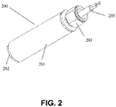
- FIG. 2 illustrates a perspective view of a flameproof surge protector according to an embodiment of the present utility model.
- FIG. 3a illustrates a front view of the flameproof surge protector according to an embodiment of the present utility model.
- FIG. 3b illustrates a right view of the flameproof surge protector according to an embodiment of the utility model.
- FIG. 3c illustrates a left view of the flameproof surge protector according to an embodiment of the present utility model.
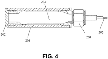
- FIG. 4 illustrates a cross-sectional schematic diagram of the flameproof surge protector according to an embodiment of the present utility model.
- a flameproof surge protector 200 provided by the present utility model includes a surge protector main body 204, a flameproof enclosure 201, a flameproof stopper plug 202, and a flameproof cable gland 203.
- One end of the flameproof enclosure 201 is connected to the flameproof stopper plug 202, and the other end thereof is connected to the flameproof cable gland 203.
- the surge protector body 204 has an elongated shape and is disposed inside the flameproof enclosure 201, and a cable 205 is drawn out of the surge protector main body 204 by means of the flameproof cable gland 203.
- the flameproof enclosure 201 is threadedly connected to the flameproof stopper plug 202.
- the flameproof enclosure 201 is threadedly connected to the flameproof cable gland 203.
- the two ends of the flameproof enclosure 201 are configured as threaded joints that should conform to a corresponding explosion-proof standard.
- the thread length and the number of engaged threads at the threaded joint should conform to a corresponding explosion-proof standard.
- the explosion-proof standard is the national standard "GB 3836.2 Explosive atmospheres - Part 2".
- the explosion-proof standard is the International Electrotechnical Commission Standard IEC 60079-1.
- the minimum number of engaged threads at the threaded joint is 5.
- the minimum axial length of thread engagement at the threaded joint is 8 mm.
- the minimum axial length of thread engagement at the threaded joint is 5 mm.
- the minimum thread pitch at the threaded joint is 0.7 mm.
- the flameproof enclosure 201 is made of a metallic material that is preferably aluminum.
- a corresponding manufacturing process for the flameproof enclosure 201 is an extrusion process or a casting process.
- the flameproof enclosure 201 has an interior cavity, that is, a flameproof chamber, having a cylindrical shape.
- the flameproof chamber can also be made in other shapes such as square, but cylindrical flameproof chambers tend to have sufficient strength to pass a flameproof pressure test and are therefore preferred embodiments.
- one end of the flameproof enclosure 201 is connected to the flameproof stopper plug 202, and the flameproof stopper plug 202 blocks the one end of the flameproof enclosure 201, isolating the flameproof enclosure 201 from being affected by internal and external pressure, temperature, and the like.
- the flameproof stopper plug 202 is threadedly connected to the flameproof enclosure 201.
- the flameproof stopper plug 202 is made of a metallic material.
- the flameproof stopper plug 202 having a model number M25 meets a corresponding explosion-proof standard, serves as an assembly part that is certified as explosion-proof, and is equivalent to a standard part used in the explosion-proof industry.
- the other end of the flameproof enclosure 201 is the flameproof cable gland 203, and the flameproof cable gland 203 blocks the other end of the flameproof enclosure 201 and draws out the cable 205.
- the cable 205 is an input/output cable of the surge protector main body 204.
- the flameproof cable gland 203 is threadedly connected to the flameproof enclosure 201.
- Cable glands are also known as waterproof cable connectors or cable-fixing heads, and are widely used for fixing and protecting electrical wires or cables of mechanical apparatuses or electronics, marine electronics, and corrosion prevention apparatuses. Cable glands are used in all portions from which cables are drawn out.
- the flameproof cable gland 203 having a model number M25 meets a corresponding explosion-proof standard, serves as an assembly part that is certified as explosion-proof, and is equivalent to a standard part used in the explosion-proof industry.
- the flameproof cable gland 203 has an outer housing made of a metallic material, is internally provided with a seal ring holding the cable 205 for fastening and sealing the cable 205.
- Fastening the cable 205 by means of the flameproof cable gland 203 refers to locking the cable 205 by means of the flameproof cable gland 203 so as to prevent the cable 205 from moving axially or rotating radially, which ensures that the cable 205 can be properly connected.
- Sealing the cable 205 by means of the flameproof cable gland 203 refers to protecting the cable 205 against dust and water.
- the flameproof chamber inside the flameproof enclosure 201 is provided with the surge protector main body 204.
- the surge protector main body 204 may be a general surge protector.
- the surge protector main body 204 In order to reduce the size of the flameproof surge protector 200, the surge protector main body 204 must have an elongated shape.
- the surge protection capability of the flameproof surge protector 200 includes the following parameters:
- the elongated shape of the surge protector main body 204 allows the flameproof enclosure 201 to be made by an extrusion process rather than using a mold for casting.
- the flameproof surge protector 200 provided by the present utility model includes the flameproof enclosure 201, which can be made of aluminum and formed by extrusion molding. One end of the flameproof enclosure 201 is inserted into the flameproof stopper plug 202 having a model number M25, and the other end thereof draws out the cable 205 using the flameproof cable gland 203 having a model number M25.
- FIG. 5 illustrates a schematic diagram of an installation arrangement of the flameproof surge protector according to an embodiment of the present utility model.
- the flameproof surge protector 200 is small and thus suitable for being fixed inside an explosion-proof lamp 300.
- the flameproof surge protector provided by the present utility model has a simple structure and small size, can be used easily and installed inside an explosion-proof lamp, further protects a circuit inside the lamp, prevents the circuit from being damaged by surges, and is safe and reliable.
Landscapes
- Emergency Protection Circuit Devices (AREA)
Abstract
Description
- The present utility model relates to the field of protection circuit devices and more particularly relates to a flameproof surge protector.
- Explosion-proof electrical apparatuses mainly refer to electrical apparatuses used at hazardous, potentially flammable, or potentially explosive locations. Commonly used explosion-proof electrical apparatuses are mainly classified into explosion-proof motors, explosion-proof transformers, explosion-proof switch-based apparatuses, explosion-proof lamps, and the like.
- Explosion-proof lamps are prone to damage or even failure due to the interference of surge current and surge voltage. A surge refers to a current or voltage spike momentarily generated in an electrical loop or a communication line due to external interference. In order to prevent a surge from damaging an explosion-proof lamp, a surge protector must be installed in a circuit.
- A surge protector is an electronic device that provides safety protection for electronic devices, instruments, and communication lines. When a surge occurs in a circuit, a surge protector can perform shunting in a very short time to prevent the surge from damaging other devices in the circuit loop.
- However, current surge protectors are generally large, have complex structures, cannot be easily installed and used in a narrow space inside an explosion-proof lamp, and can only be installed in an external circuit.
- For example, Chinese invention
CN201510721498.5 FIG. 1 illustrates a schematic diagram of the surge protector provided by said invention. The explosion-proof surge protector shown inFIG. 1 includes aflameproof enclosure 101, asurge protector 102, afuse 103, aconnection member 104, amulti-point ground terminal 105, an explosion-proof cable clamp 106, wherein thefuse 103, theconnection member 104, themulti-point ground terminal 105 are disposed in theflameproof enclosure 101, the explosion-proof cable clamp 106 is disposed at theflameproof enclosure 101, and themulti-point ground terminal 105 is connected to ground by means of a wire. The explosion-proof surge protector provided by said invention has a complex structure, is overall excessively large, and cannot be easily installed in the interior space of an explosion-proof lamp. - The object of the present utility model is to provide a flameproof surge protector that solves the issue in which the surge protector in the prior art is excessively large and cannot be easily employed in an explosion-proof lamp.
- In order to achieve the above object, the present utility model provides a flameproof surge protector, comprising a surge protector main body, a flameproof enclosure, a flameproof stopper plug, and a flameproof cable gland, wherein
- one end of the flameproof enclosure is connected to the flameproof stopper plug, and the other end thereof is connected to the flameproof cable gland; and
- the surge protector main body has an elongated shape and is disposed inside the flameproof enclosure, and a cable is drawn out of the surge protector main body by means of the flameproof cable gland.
- In one embodiment, the two ends of the flameproof enclosure are configured as threaded joints, the flameproof enclosure is threadedly connected to the flameproof stopper plug, and the flameproof enclosure is threadedly connected to the flameproof cable gland.
- In one embodiment, the flameproof enclosure has a flameproof chamber having a cylindrical shape.
- In one embodiment, the flameproof cable gland has an outer housing made of a metallic material, is internally provided with a seal ring holding the cable for fastening and sealing the cable.
- In one embodiment, the minimum number of engaged threads at the threaded joint is 5.
- In one embodiment, the minimum thread pitch at the threaded joint is 0.7 mm.
- In one embodiment, the insertion volume is greater than 100 cm3 and the minimum axial length of thread engagement is 8 mm.
- In one embodiment, the insertion volume is less than 100 cm3 and the minimum axial length of thread engagement is 5 mm.
- In one embodiment, the flameproof enclosure is made of a metallic material and is made by an extrusion process or a casting process.
- In one embodiment, the surge protector main body has a maximum open-circuit voltage of 10000 V, a maximum short-circuit current of 5000 A, and a response time of less than 25 ns.
- The flameproof surge protector provided by the present utility model has a simple structure and small size, can be used easily and installed inside an explosion-proof lamp, further protects a circuit inside the lamp, prevents the circuit from being damaged by surges, and is safe and reliable.
- The above and other features, properties, and advantages of the present utility model will become more apparent from the following description when taken in conjunction with the accompanying drawings and embodiments. The same reference numerals are used throughout the drawings to represent the same features, wherein:
-
FIG. 1 illustrates a schematic diagram of a prior art surge protector; -
FIG. 2 illustrates a perspective view of a flameproof surge protector according to an embodiment of the present utility model; -
FIG. 3a illustrates a front view of the flameproof surge protector according to an embodiment of the present utility model; -
FIG. 3b illustrates a right view of the flameproof surge protector according to an embodiment of the utility model; -
FIG. 3c illustrates a left view of the flameproof surge protector according to an embodiment of the present utility model; -
FIG. 4 illustrates a cross-sectional schematic diagram of the flameproof surge protector according to an embodiment of the present utility model; -
FIG. 5 illustrates a schematic diagram of an installation arrangement of the flameproof surge protector according to an embodiment of the present utility model. - The reference numerals in the figures refer to the following:
- 101 flameproof enclosure;
- 102 surge protector;
- 103 fuse;
- 104 connection member;
- 105 multi-point ground terminal;
- 106 explosion-proof cable clamp;
- 200 flameproof surge protector;
- 201 flameproof enclosure;
- 202 flameproof stopper plug;
- 203 flameproof cable gland;
- 204 surge protector main body;
- 205 cable;
- 300 explosion-proof lamp.
- In order to make the object, technical solutions, and advantages of the present utility model more apparent and comprehensible, the present utility model is further described in detail below with reference to the accompanying drawings and embodiments. It should be appreciated that the specific embodiments described herein are merely illustrative of the utility model and are not intended to limit the utility model.
- Provided in the present utility model is a flameproof surge protector that can be used in explosion-proof lamps or lighting devices operating in outdoor or indoor areas in hazardous fields, such as fields related to corrosion, moisture, processing and manufacturing, pharmaceuticals, and petrochemicals.
- Flameproof protection is an explosion-proof protection method that employs the technique of allowing internal explosions but preventing flame propagation, and is one of the most commonly used types of explosion-proof method. Flameproof protection refers to the use of a flameproof enclosure to prevent explosions. A flameproof enclosure can withstand the explosion pressure of an explosive gas mixture therein and prevent an internal explosion from propagating to explosive mixtures around the enclosure. The enclosure is a structure designed using a principle of explosion-proof protection by means of a gap, that is, using a metal gap to prevent the propagation of an explosive flame and cool the temperature of an explosive product, so as to achieve flame extinction and temperature reduction and thereby suppress explosion propagation.
-
FIG. 2 illustrates a perspective view of a flameproof surge protector according to an embodiment of the present utility model.FIG. 3a illustrates a front view of the flameproof surge protector according to an embodiment of the present utility model.FIG. 3b illustrates a right view of the flameproof surge protector according to an embodiment of the utility model.FIG. 3c illustrates a left view of the flameproof surge protector according to an embodiment of the present utility model.FIG. 4 illustrates a cross-sectional schematic diagram of the flameproof surge protector according to an embodiment of the present utility model. - In the embodiments shown in
FIGs. 2-4 , aflameproof surge protector 200 provided by the present utility model includes a surge protectormain body 204, aflameproof enclosure 201, aflameproof stopper plug 202, and aflameproof cable gland 203. - One end of the
flameproof enclosure 201 is connected to theflameproof stopper plug 202, and the other end thereof is connected to theflameproof cable gland 203. - The
surge protector body 204 has an elongated shape and is disposed inside theflameproof enclosure 201, and acable 205 is drawn out of the surge protectormain body 204 by means of theflameproof cable gland 203. - The
flameproof enclosure 201 is threadedly connected to theflameproof stopper plug 202. - The
flameproof enclosure 201 is threadedly connected to theflameproof cable gland 203. - The two ends of the
flameproof enclosure 201 are configured as threaded joints that should conform to a corresponding explosion-proof standard. - Still further, the thread length and the number of engaged threads at the threaded joint should conform to a corresponding explosion-proof standard.
- Optionally, the explosion-proof standard is the national standard "GB 3836.2 Explosive atmospheres - Part 2".
- Optionally, the explosion-proof standard is the International Electrotechnical Commission Standard IEC 60079-1.
- Still further, the minimum number of engaged threads at the threaded joint is 5.
- Still further, if the insertion volume is greater than 100 cm3, the minimum axial length of thread engagement at the threaded joint is 8 mm.
- Still further, if the insertion volume is not greater than 100 cm3, the minimum axial length of thread engagement at the threaded joint is 5 mm.
- Still further, the minimum thread pitch at the threaded joint is 0.7 mm.
- In the embodiments shown in
FIGs. 2-4 , theflameproof enclosure 201 is made of a metallic material that is preferably aluminum. - In the embodiments shown in
FIGs. 2-4 , a corresponding manufacturing process for theflameproof enclosure 201 is an extrusion process or a casting process. - In embodiments shown in
FIGs. 2-4 , theflameproof enclosure 201 has an interior cavity, that is, a flameproof chamber, having a cylindrical shape. - Obviously, the flameproof chamber can also be made in other shapes such as square, but cylindrical flameproof chambers tend to have sufficient strength to pass a flameproof pressure test and are therefore preferred embodiments.
- In the embodiments shown in
FIGs. 2-4 , one end of theflameproof enclosure 201 is connected to theflameproof stopper plug 202, and theflameproof stopper plug 202 blocks the one end of theflameproof enclosure 201, isolating theflameproof enclosure 201 from being affected by internal and external pressure, temperature, and the like. - The
flameproof stopper plug 202 is threadedly connected to theflameproof enclosure 201. - In the embodiments shown in
FIGs. 2-4 , theflameproof stopper plug 202 is made of a metallic material. - In the embodiments shown in
FIGs. 2-4 , theflameproof stopper plug 202 having a model number M25 meets a corresponding explosion-proof standard, serves as an assembly part that is certified as explosion-proof, and is equivalent to a standard part used in the explosion-proof industry. - In the embodiments shown in
FIGs 2-4 , the other end of theflameproof enclosure 201 is theflameproof cable gland 203, and theflameproof cable gland 203 blocks the other end of theflameproof enclosure 201 and draws out thecable 205. Thecable 205 is an input/output cable of the surge protectormain body 204. - The
flameproof cable gland 203 is threadedly connected to theflameproof enclosure 201. - Cable glands are also known as waterproof cable connectors or cable-fixing heads, and are widely used for fixing and protecting electrical wires or cables of mechanical apparatuses or electronics, marine electronics, and corrosion prevention apparatuses. Cable glands are used in all portions from which cables are drawn out.
- In the embodiments shown in
FIGs. 2-4 , theflameproof cable gland 203 having a model number M25 meets a corresponding explosion-proof standard, serves as an assembly part that is certified as explosion-proof, and is equivalent to a standard part used in the explosion-proof industry. - The
flameproof cable gland 203 has an outer housing made of a metallic material, is internally provided with a seal ring holding thecable 205 for fastening and sealing thecable 205. - Fastening the
cable 205 by means of theflameproof cable gland 203 refers to locking thecable 205 by means of theflameproof cable gland 203 so as to prevent thecable 205 from moving axially or rotating radially, which ensures that thecable 205 can be properly connected. - Sealing the
cable 205 by means of theflameproof cable gland 203 refers to protecting thecable 205 against dust and water. - In the embodiments shown in
FIGs. 2-4 , the flameproof chamber inside theflameproof enclosure 201 is provided with the surge protectormain body 204. - The surge protector
main body 204 may be a general surge protector. - Considering the limited interior space of an explosion-proof lamp, in order to reduce the size of the
flameproof surge protector 200, the surge protectormain body 204 must have an elongated shape. - In addition, there are no special requirements for other parameters of the surge protector main body.
- In the embodiments shown in
FIGs. 2-4 , the surge protection capability of theflameproof surge protector 200 includes the following parameters: - a maximum open-circuit voltage Uoc of 10000 V;
- a maximum short-circuit current Isc of 5000 A;
- a response time of less than 25 ns;
- a maximum continuous voltage of 320 V;
- a rated voltage of 100-300 V;
- a maximum discharge current Imax (8/20 us) of 10000 A; and
- a nominal discharge current In of 5000 A.
- In the present utility model, both explosion-proof and space requirements can be achieved by employing a general surge protector having an elongated shape, because of the following:
- 1) The surge protector
main body 204 having an elongated shape allows a flameproof chamber of theflameproof enclosure 201 to be made cylindrical, wherein the cylindrical flameproof chamber tends to have sufficient strength; - 2) The
flameproof enclosure 201 can be made cylindrical, and the two ends thereof can be configured as threaded joints, such that the flameproof enclosure can achieve explosion-proof functions more easily than a square-shaped flameproof enclosure; - 3) The
flameproof enclosure 201 can be made cylindrical, and the two ends thereof are respectively connected to a smallerflameproof stopper plug 202 and a smallerflameproof cable gland 203, such that the flameproof enclosure can have a smaller size than a square-shaped flameproof enclosure. - Additionally, the elongated shape of the surge protector
main body 204 allows theflameproof enclosure 201 to be made by an extrusion process rather than using a mold for casting. - The
flameproof surge protector 200 provided by the present utility model includes theflameproof enclosure 201, which can be made of aluminum and formed by extrusion molding. One end of theflameproof enclosure 201 is inserted into theflameproof stopper plug 202 having a model number M25, and the other end thereof draws out thecable 205 using theflameproof cable gland 203 having a model number M25. -
FIG. 5 illustrates a schematic diagram of an installation arrangement of the flameproof surge protector according to an embodiment of the present utility model. As shown inFIG. 5 , theflameproof surge protector 200 is small and thus suitable for being fixed inside an explosion-proof lamp 300. - The flameproof surge protector provided by the present utility model has a simple structure and small size, can be used easily and installed inside an explosion-proof lamp, further protects a circuit inside the lamp, prevents the circuit from being damaged by surges, and is safe and reliable.
- Although the above methods are illustrated and described as a series of actions for simplicity of explanation, it should be understood and appreciated that these methods are not limited by the order of the actions because, according to one or more embodiments, some actions may occur in different orders and/or occur concurrently with other actions illustrated and described herein or not illustrated and described herein but understood by those skilled in the art.
- As set forth in the present application and the claims, the terms "a", "an", "one", and/or "the" are not specifically singular and can be plural, unless the context clearly indicates otherwise. In general, the terms "include" and "comprise" indicate only the inclusion of explicitly identified steps or elements, which do not constitute an exclusive list, and methods or apparatuses may also comprise other steps or elements.
- The above embodiments are provided to those skilled in the art to implement or use the present utility model. Those skilled in the art can make various modifications or changes without departing from the concept of the utility model, and thus the scope of protection of the present utility model is not limited by the above embodiments, but should be consistent to the maximum extent with the innovative features mentioned in the claims.
Claims (10)
- A flameproof surge protector, characterized by comprising a surge protector main body, a flameproof enclosure, a flameproof stopper plug, and a flameproof cable gland, whereinone end of the flameproof enclosure is connected to the flameproof stopper plug, and the other end thereof is connected to the flameproof cable gland; andthe surge protector main body has an elongated shape and is disposed inside the flameproof enclosure, and a cable is drawn out of the surge protector main body by means of the flameproof cable gland.
- The flameproof surge protector according to claim 1, wherein:
the two ends of the flameproof enclosure are configured as threaded joints, the flameproof enclosure is threadedly connected to the flameproof stopper plug, and the flameproof enclosure is threadedly connected to the flameproof cable gland. - The flameproof surge protector according to claim 1, wherein the flameproof enclosure has a flameproof chamber having a cylindrical shape.
- The flameproof surge protector according to claim 1, wherein the flameproof cable gland has an outer housing made of a metallic material, is internally provided with a seal ring holding the cable for fastening and sealing the cable.
- The flameproof surge protector according to claim 2, wherein the minimum number of engaged threads at the threaded joint is 5.
- The flameproof surge protector according to claim 2, wherein the minimum thread pitch at the threaded joint is 0.7 mm.
- The flameproof surge protector according to claim 2, wherein the insertion volume is greater than 100 cm3 and the minimum axial length of thread engagement is 8 mm.
- The flameproof surge protector according to claim 2, wherein the insertion volume is less than 100 cm3 and the minimum axial length of thread engagement is 5 mm.
- The flameproof surge protector according to claim 1, wherein the flameproof enclosure is made of a metallic material and is made by an extrusion process or a casting process.
- The flameproof surge protector according to claim 1, wherein the surge protector main body has a maximum open-circuit voltage of 10000 V, a maximum short-circuit current of 5000 A, and a response time of less than 25 ns.
Applications Claiming Priority (2)
| Application Number | Priority Date | Filing Date | Title |
|---|---|---|---|
| CN202020143385.8U CN211830199U (en) | 2020-01-22 | 2020-01-22 | Explosion-proof surge protector |
| PCT/IB2021/000034 WO2021148885A1 (en) | 2020-01-22 | 2021-01-22 | Explosion-proof surge protector |
Publications (1)
| Publication Number | Publication Date |
|---|---|
| EP4096037A1 true EP4096037A1 (en) | 2022-11-30 |
Family
ID=72993212
Family Applications (1)
| Application Number | Title | Priority Date | Filing Date |
|---|---|---|---|
| EP21711950.2A Pending EP4096037A1 (en) | 2020-01-22 | 2021-01-22 | Explosion-proof surge protector |
Country Status (4)
| Country | Link |
|---|---|
| US (1) | US11973324B2 (en) |
| EP (1) | EP4096037A1 (en) |
| CN (1) | CN211830199U (en) |
| WO (1) | WO2021148885A1 (en) |
Families Citing this family (2)
| Publication number | Priority date | Publication date | Assignee | Title |
|---|---|---|---|---|
| FR3086115B1 (en) * | 2018-09-17 | 2021-09-24 | Naval Energies | TEST SYSTEM FOR THE TIGHTNESS OF A BULKHEAD CABLE GLAND, ESPECIALLY OF A SUBMERGEABLE ELECTRICAL CONNECTOR |
| CN117979665B (en) * | 2024-04-02 | 2024-05-31 | 常州新泽监控设备有限公司 | Optical transceiver with explosion-proof function |
Citations (2)
| Publication number | Priority date | Publication date | Assignee | Title |
|---|---|---|---|---|
| DE69413494T2 (en) * | 1993-11-03 | 1999-05-12 | Framatome Connectors International, Paris La Defense | Improvements to sealing arrangements for a cable gland |
| DE102006034224B3 (en) * | 2005-07-28 | 2007-11-22 | Hidde, Axel R., Dr. | Ventilated guide for sealed guiding of electric cable through opening in housing wall, includes outer hexagonal central component with aeration channel-forming holes and channels in lower part |
Family Cites Families (17)
| Publication number | Priority date | Publication date | Assignee | Title |
|---|---|---|---|---|
| US4345290A (en) | 1980-09-22 | 1982-08-17 | Johnson Richard H | Electrical transient suppressor |
| US4425609A (en) | 1982-09-29 | 1984-01-10 | General Electric Company | Fixture for hazardous area |
| US4649457A (en) * | 1984-02-17 | 1987-03-10 | B. H. Tytewadd Marketing, Incorporated | Surge protection device |
| CA1242497A (en) * | 1984-11-28 | 1988-09-27 | Teleco Oilfield Services Inc. | Explosion and flame proof electrical connector protective assembly |
| DE19622140A1 (en) * | 1996-06-01 | 1997-12-04 | Asea Brown Boveri | Surge arresters |
| US5798910A (en) | 1996-08-29 | 1998-08-25 | Caloritech Inc. | Sealable housing for electrical components |
| DE19942633A1 (en) * | 1999-09-07 | 2001-03-08 | Abb Hochspannungstechnik Ag | Surge arresters |
| US20090135607A1 (en) | 2007-11-27 | 2009-05-28 | Cooper Technologies Company | Lighting fixture and method |
| KR101201153B1 (en) | 2012-08-21 | 2012-11-13 | (주)디에이치코프 | Explosion Proof LED Lighting Fixture |
| CN203010328U (en) | 2013-01-08 | 2013-06-19 | 厦门市广明源光电科技有限公司 | LED explosion-proof lamp |
| KR101533314B1 (en) | 2013-05-21 | 2015-07-03 | 에스케이씨라이팅 주식회사 | Light emitting diode explosion-proof light |
| TWI521169B (en) | 2014-06-12 | 2016-02-11 | Modular LED explosion - proof lights | |
| US9431158B2 (en) * | 2014-08-19 | 2016-08-30 | Longke Electronics (Huiyang) Co., Ltd. | Barrel-shaped fireproof and explosion-proof surge protection device with over-temperature protection function |
| CN105546495B (en) | 2016-01-08 | 2019-04-26 | 湖南玖泓节能科技有限公司 | An LED explosion-proof light |
| KR101876637B1 (en) | 2016-10-31 | 2018-07-13 | 한국생산기술연구원 | Explosion-proof lamp structure |
| CN206300093U (en) | 2016-12-31 | 2017-07-04 | 上海旗升电气股份有限公司 | A LED explosion-proof lamp with a vacuum phase change heat dissipation structure |
| US11209599B2 (en) * | 2018-07-05 | 2021-12-28 | Senko Advanced Components, Inc. | Ingress protected, outdoor rated adapter and method of assembly to an outdoor connector |
-
2020
- 2020-01-22 CN CN202020143385.8U patent/CN211830199U/en active Active
-
2021
- 2021-01-22 WO PCT/IB2021/000034 patent/WO2021148885A1/en not_active Ceased
- 2021-01-22 US US17/794,605 patent/US11973324B2/en active Active
- 2021-01-22 EP EP21711950.2A patent/EP4096037A1/en active Pending
Patent Citations (2)
| Publication number | Priority date | Publication date | Assignee | Title |
|---|---|---|---|---|
| DE69413494T2 (en) * | 1993-11-03 | 1999-05-12 | Framatome Connectors International, Paris La Defense | Improvements to sealing arrangements for a cable gland |
| DE102006034224B3 (en) * | 2005-07-28 | 2007-11-22 | Hidde, Axel R., Dr. | Ventilated guide for sealed guiding of electric cable through opening in housing wall, includes outer hexagonal central component with aeration channel-forming holes and channels in lower part |
Non-Patent Citations (1)
| Title |
|---|
| See also references of WO2021148885A1 * |
Also Published As
| Publication number | Publication date |
|---|---|
| WO2021148885A1 (en) | 2021-07-29 |
| CN211830199U (en) | 2020-10-30 |
| US20230073865A1 (en) | 2023-03-09 |
| US11973324B2 (en) | 2024-04-30 |
Similar Documents
| Publication | Publication Date | Title |
|---|---|---|
| US7507105B1 (en) | Hazardous area coupler device | |
| TWI538317B (en) | Cable termination system | |
| EP3758177B1 (en) | Electromagnetic compatibility type cable locking joint | |
| US11973324B2 (en) | Flameproof surge protector | |
| US8137136B1 (en) | Electrical disconnect for hazardous areas | |
| US20120292100A1 (en) | Accessible indirect entry cable gland | |
| US3727108A (en) | Surge arrester | |
| EP3097617B1 (en) | Lightning arrester | |
| US8574007B2 (en) | Electrical connector having a shielding adapter to radially compress a shielding ferrule onto a cable | |
| US4345290A (en) | Electrical transient suppressor | |
| EP3028348B1 (en) | Compact high voltage connector | |
| KR100379867B1 (en) | An elbow connector for pad mounted transformer with fuse mounted inside | |
| CN203617488U (en) | Wire strand breakage prevention protection device | |
| EP2518843B1 (en) | Device for high-voltage electric connection between electric devices | |
| KR101816241B1 (en) | High voltage shield cable connector used for airfield light | |
| RU53079U1 (en) | BRANCH CONNECTING BOX | |
| CN224138711U (en) | A hermetically sealed electric heating cable current limiter assembly | |
| RU2006120C1 (en) | Cable stuffing arrangement | |
| CN219477033U (en) | Explosion-proof waterproof type lightning protection device | |
| CN223613040U (en) | A 35kV line lightning protection device | |
| AU2021105156A4 (en) | Flameproof junction box | |
| JP6685291B2 (en) | Terminal feedthrough | |
| CN223297301U (en) | Junction box, inverter and photovoltaic system | |
| CN211266292U (en) | Safety protection structure of cable core | |
| RU45867U1 (en) | SHELL OF ELECTRICAL APPLIANCES |
Legal Events
| Date | Code | Title | Description |
|---|---|---|---|
| STAA | Information on the status of an ep patent application or granted ep patent |
Free format text: STATUS: UNKNOWN |
|
| STAA | Information on the status of an ep patent application or granted ep patent |
Free format text: STATUS: THE INTERNATIONAL PUBLICATION HAS BEEN MADE |
|
| PUAI | Public reference made under article 153(3) epc to a published international application that has entered the european phase |
Free format text: ORIGINAL CODE: 0009012 |
|
| STAA | Information on the status of an ep patent application or granted ep patent |
Free format text: STATUS: REQUEST FOR EXAMINATION WAS MADE |
|
| 17P | Request for examination filed |
Effective date: 20220805 |
|
| AK | Designated contracting states |
Kind code of ref document: A1 Designated state(s): AL AT BE BG CH CY CZ DE DK EE ES FI FR GB GR HR HU IE IS IT LI LT LU LV MC MK MT NL NO PL PT RO RS SE SI SK SM TR |
|
| DAV | Request for validation of the european patent (deleted) | ||
| DAX | Request for extension of the european patent (deleted) | ||
| P01 | Opt-out of the competence of the unified patent court (upc) registered |
Effective date: 20230521 |
|
| STAA | Information on the status of an ep patent application or granted ep patent |
Free format text: STATUS: EXAMINATION IS IN PROGRESS |
|
| 17Q | First examination report despatched |
Effective date: 20250604 |
|
| RIN1 | Information on inventor provided before grant (corrected) |
Inventor name: WANG, CHUNHUAI Inventor name: LI, YURU Inventor name: MAN, HAIJUN Inventor name: LU, ROTTON |