EP3097617B1 - Lightning arrester - Google Patents
Lightning arrester Download PDFInfo
- Publication number
- EP3097617B1 EP3097617B1 EP15701252.7A EP15701252A EP3097617B1 EP 3097617 B1 EP3097617 B1 EP 3097617B1 EP 15701252 A EP15701252 A EP 15701252A EP 3097617 B1 EP3097617 B1 EP 3097617B1
- Authority
- EP
- European Patent Office
- Prior art keywords
- lightning arrester
- mainbody
- housing
- holes
- base
- Prior art date
- Legal status (The legal status is an assumption and is not a legal conclusion. Google has not performed a legal analysis and makes no representation as to the accuracy of the status listed.)
- Active
Links
Images

Classifications
-
- H—ELECTRICITY
- H01—ELECTRIC ELEMENTS
- H01C—RESISTORS
- H01C7/00—Non-adjustable resistors formed as one or more layers or coatings; Non-adjustable resistors made from powdered conducting material or powdered semi-conducting material with or without insulating material
- H01C7/10—Non-adjustable resistors formed as one or more layers or coatings; Non-adjustable resistors made from powdered conducting material or powdered semi-conducting material with or without insulating material voltage responsive, i.e. varistors
- H01C7/12—Overvoltage protection resistors; Arresters
- H01C7/126—Means for protecting against excessive pressure or for disconnecting in case of failure
-
- H—ELECTRICITY
- H01—ELECTRIC ELEMENTS
- H01C—RESISTORS
- H01C1/00—Details
- H01C1/02—Housing; Enclosing; Embedding; Filling the housing or enclosure
-
- H—ELECTRICITY
- H01—ELECTRIC ELEMENTS
- H01C—RESISTORS
- H01C1/00—Details
- H01C1/14—Terminals or tapping points specially adapted for resistors; Arrangements of terminals or tapping points on resistors
-
- H—ELECTRICITY
- H01—ELECTRIC ELEMENTS
- H01T—SPARK GAPS; OVERVOLTAGE ARRESTERS USING SPARK GAPS; SPARKING PLUGS; CORONA DEVICES; GENERATING IONS TO BE INTRODUCED INTO NON-ENCLOSED GASES
- H01T1/00—Details of spark gaps
- H01T1/15—Details of spark gaps for protection against excessive pressure
-
- H—ELECTRICITY
- H01—ELECTRIC ELEMENTS
- H01C—RESISTORS
- H01C7/00—Non-adjustable resistors formed as one or more layers or coatings; Non-adjustable resistors made from powdered conducting material or powdered semi-conducting material with or without insulating material
- H01C7/10—Non-adjustable resistors formed as one or more layers or coatings; Non-adjustable resistors made from powdered conducting material or powdered semi-conducting material with or without insulating material voltage responsive, i.e. varistors
- H01C7/105—Varistor cores
- H01C7/108—Metal oxide
- H01C7/112—ZnO type
Definitions
- the present invention relates to a lightning arrester, in particular to a lightning arrester including a pressure relief apparatus.
- GIS gas insulation switchgear
- An existing plug-in lightning arrester for below 66kV employs a standard interface at the upper plug-in joint, and employs ZnO resistance pieces as main components of an overvoltage protection device in an interior thereof. Though a part of arrester products has pressure relief function, the electrical field distribution in this type of lightning arresters is very uneven by simulation calculation of the electrical field distribution, and a pressure equalizer is needed to optimize the electrical field distribution so as to provide a reliable electrical performance and a long-term running stability.
- US 4 136 299 A a lightning arrester is shown in which the pressure ways exits in a straight manner from a lower end.
- US 3 588 578 A discloses a lightning arrester in which the pressure wave is redirected 180 degrees and fragments are filtered out from the pressure wave.
- CH 524 903 A shows a lightning arrester in which a pot-like element carrying a grounding line is ejected by the pressure wave.
- the present invention provides a lightning arrester to ensure the reliable electrical connection according to claim 1. It is the object of the invention to provide a lightning arrester that is safer. This object is achieved when the encapsulation cap comprises:
- the present invention provides a lightning arrester which has a directional pressure relief apparatus, thus the damage of other electrical equipments and accessories due to the runaway explosive fragments of the lightning arrester may be avoided.
- the present invention further provides a lightning arrester which includes a built-in pressure equalizer to optimize the electrical distribution in the lightning arrester and increase the product life time.
- a lightning arrester comprising: a housing, a mainbody partially mounted in the housing, an encapsulation cap mounted at a first end of the housing and an elastic apparatus compressed between the encapsulation cap and the mainbody.
- the encapsulation cap comprises: a circular base mounted at the first end of the housing; and a mounting portion formed at a substantial center of the base, a first end of the elastic apparatus being mounted on the mounting portion and a second end thereof being abutted against the mainbody.
- the mounting portion is configured to be a cylinder projecting from the base, and a part of the elastic apparatus is mounted in the cylinder.
- the elastic apparatus comprises: a spring having a first end mounted in the cylinder; and an engaging part having a first end engaged with a second end of the spring, and a second end mounted in the mainbody.
- the mainbody comprises: an insulator having a first portion mounted in the housing and a second portion protruding from the second end of the housing, a cylindrical receiving portion being formed in the first portion of the insulator; a plurality of resistance pieces disposed in the receiving portion from a first end of the receiving portion; at least two connecting parts disposed at two ends of the plurality of resistance pieces, respectively; and an electrode passing through the second portion of the insulator and connected to a first connecting part of the connecting parts.
- the second end of the engaging part is screwed to a second connecting part opposite to the first connecting part.
- the mainbody further comprises a shielding cover which has a substantially bell shape and extends from a portion where the electrode is engaged with the first connecting part towards the resistance pieces.
- a pressure relief apparatus is disposed on the encapsulation cap.
- the pressure relief apparatus comprises: at least one first through hole formed on the base at the outer side of the mounting portion; at least one annular films covering the first through holes and configured to be cracked when the pressure between the mainbody and the encapsulation cap is more than the predetermined value; and an annular holding part configured to hold the annular films on the base, at least one second through holes being formed on the annular holding part and aligned substantially with the first through holes, respectively.
- the cross sections of the first through holes and second through holes are formed to be substantially arc shape.
- the holding part is mounted on the base via bolts.
- a fixing cylinder for surrounding the resistance pieces is disposed in the receiving portion.
- the pressure relief apparatus is disposed at the bottom end of the lightning arrester, during normal operation of the lightning arrester, the arrester mainbody will be effectively sealed and isolated from the outer environment by the annular film of the pressure relief apparatus, when the energy of the overvoltage applied across the lightning arrester is beyond the energy which the lightning arrester can withstand, the dynamic thermal balance of the lightning arrester is broken and thus explosion occurs.
- the huge impact energy will open the pressure relief port to achieve a directional pressure relief, thus preventing runaway explosive fragments of the lightning arrester from damaging other electrical equipments and accessories.
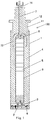
- a lightning arrester 100 which may be installed in a gas insulated switchgear (GIS) in a field such as power stations or substations, in order to protect electrical equipments such as the switchgears or transformers and to prevent abnormal voltage from invading the electrical equipments through power cable in the case such as lightning occurring.
- the lightning arrester 100 comprises: a housing 1 made from metallic material such as aluminum alloy or the like; a mainbody partially mounted in the housing 1; an encapsulation cap 2 mounted at a first end (the lower end in Fig.1 ) of the housing 1; and an elastic apparatus 3 compressed between the encapsulation cap 2 and the mainbody.
- the mainbody of the lightning arrester can be closely attached to the encapsulation cap 2 arranged at the end, so that reliable electrical connection between the mainbody and the encapsulation cap is assured, and overvoltage in the gas insulated switchgear can be released to the ground smoothly through the encapsulation cap 2 and the housing 1 for ground connection.
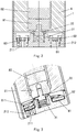
- the encapsulation cap 2 made from the metallic material such as aluminum alloy or the like comprises: a circular base 21 mounted at the first end of the housing; and a mounting portion 22 formed at a substantial center of the base, a first end (the lower end in the Fig.2 ) of the elastic apparatus 3 being mounted on the mounting portion 22, and a second (the upper end in the Fig.2 ) thereof being abutted against the mainbody.
- the mounting portion 22 is configured to be a cylinder projecting from the base 21 around the center of the base 21, and a part of the elastic apparatus 3 being mounted in the cylinder.
- the elastic apparatus 3 comprising: a spring 31 made from the material such as stainless steel and an engaging part 32, wherein a first end of the spring 31 is mounted in the cylinder served as the mounting portion 22 and a second end thereof is engaged with a first end of the engaging part 32, and a second end of the engaging part 32 is mounted in the mainbody.
- a second end (the upper end in Fig.1 ) of the housing 1 is connected to an auxiliary housing 11, wherein a flange 12 is formed on the auxiliary housing 11, and the lightning arrester 100 can be installed on the electrical equipment through a plurality of connecting holes formed in the flange 12.
- the mainbody comprises: an insulator 4 made from the material such as silicone rubber, a first portion (the lower portion in Fig.1 ) of the insulator 4 being mounted in the housing 1 and a second portion (the upper portion in Fig.1 ) thereof being formed to protrude from the second end (the upper end in Fig.1 ) of the housing 1, and a cylindrical receiving portion being formed in the first portion of the insulator 4; a plurality of resistance pieces 5, for example, made of ZnO material, disposed in the receiving portion from a first end of the receiving portion; at least two connecting parts 8disposed at two ends of the plurality of resistance pieces 5; and electrodes 7, made of a conductive material, passing through the second portion of the insulator 4 and connected to a first connecting part (the upper connecting part in Fig.1 ) of the connecting parts 8.
- an insulator 4 made from the material such as silicone rubber
- the second end of the engaging part 32 is screwed to a second connecting part 81 opposite to the first connecting part. Further, a third connecting part 82 is disposed between the second connecting part 81 and the resistance pieces 5. In addition, a fixing cylinder 9 for surrounding the resistance pieces 5 is disposed in the receiving portion of the insulator 4.
- the engaging part 32 has a substantially cross shape at its axial cross-section and includes a substantially disc configuration, and a first end and a second end extending from both sides of the disc configuration.
- the mainbody further comprises a shielding cover 72 which has a substantially bell shape and extends from a portion where the electrode 7 is engaged with the first connecting part towards the resistance pieces 5.
- the electrical field distribution in the mainbody can be optimized by the arrangement of the shielding cover 72, so that the life time of the lightning arrester 100 is increased.
- a pressure relief apparatus 6 is disposed on the encapsulation cap 2.
- the pressure relief apparatus 6 comprises: at least one first through hole 211 formed on the base 21 at the outer side of the mounting portion 22 of the encapsulation cap 2; annular films 61 covering the first through holes 211 and configured to be cracked when the pressure between the mainbody and the encapsulation cap 2 is more than the predetermined value; and an annular holding part 62, for example, made of metal material, configured to hold the annular films 61 on the base 21, at least one second through hole 611 being formed on the annular holding part 62 and aligned substantially with the first through hole 211.
- the cross sections of the first through holes 211 and second through holes 611 are formed to be substantially arc shape.
- the holding part 62 is mounted on the base 21 via bolts 63.
- the mainbody of the lightning arrester is effectively sealed and isolated from the outer environment by the annular films 61, for example, made of rubber material.
- the annular films 61 for example, made of rubber material.
- each of the first through holes 211 is communicated with the corresponding one of the second through holes 611 to form the pressure relief passage, so that gas may be directed through first through holes 211 and second through holes 611 and thus directional pressure relief may be obtained, and the damage of other equipments and accessories due to runaway explosive fragments of the lightning arrester 100 is avoided.
- the fixing cylinder 9, the connecting parts 8, the shielding cover 72 and resistance pieces 5 of the mainbody may be pre-molded as one single piece which is then mounted in the housing 1; thereafter, the first end of engaging part 32 is screwed into the second connecting part 81 of the connecting parts and then the spring 31 is engaged onto the second end of engaging part 32; thereafter, the encapsulation cap 2 mounted with the pressure relief apparatus 6 is secured to the first end of housing 1; then the electrodes 7 are screwed to the first connecting part; finally, contacts 71 are connected to the electrodes 7, thereby the lightning arrester 100 according to the embodiments of the invention is obtained.
- the elastic apparatus disposed at the bottom of the housing is constructed to connect the mainbody of the lightning arrester with the encapsulation cap reliably, so that overvoltage is released smoothly to the ground through the encapsulation cap and the grounded housing.
- the insulator is made from the silicone rubber having high electrical performance, and the housing is configured to be a fully sealed metal shield of which a top end (as shown in Fig.1 ) has a standard interface dimension to engage with the inner cone insulator of GIS.
- the bell shaped shielding cover is disposed as a pressure equalizer in the lightning arrester by performing simulation calculation based on the actual electrical field distribution inside the lightning arrester, so that the electrical field distribution inside the lightning arrester is optimized and thus the life time thereof is increased.
- the mainbody of the lightning arrester will be effectively sealed and isolated from the outer environment by the annular film of the pressure relief apparatus.
- the energy of the overvoltage across the lightning arrester is beyond the predetermined energy which the lightning arrester can withstand, the dynamic thermal balance of the lightning arrester is broken and thus explosion occurs. In this case, the huge impact energy will open the annular film of the pressure relief apparatus to achieve a directional pressure relief, thus preventing runaway explosive fragments of the lightning arrester from damaging other electrical equipments and accessories.
Landscapes
- Engineering & Computer Science (AREA)
- Microelectronics & Electronic Packaging (AREA)
- Physics & Mathematics (AREA)
- Electromagnetism (AREA)
- Thermistors And Varistors (AREA)
Description
- The present invention relates to a lightning arrester, in particular to a lightning arrester including a pressure relief apparatus.
- In the prior art, it is necessary to install a lightning arrester in a gas insulation switchgear (GIS) at places such as power stations or substations in order to protect electrical equipments such as the switchgears or transformers, thus preventing abnormal voltage from invading the electrical equipments through power cables in the case such as lightning occurring.
- An existing plug-in lightning arrester for below 66kV employs a standard interface at the upper plug-in joint, and employs ZnO resistance pieces as main components of an overvoltage protection device in an interior thereof. Though a part of arrester products has pressure relief function, the electrical field distribution in this type of lightning arresters is very uneven by simulation calculation of the electrical field distribution, and a pressure equalizer is needed to optimize the electrical field distribution so as to provide a reliable electrical performance and a long-term running stability.
- In
US 4 136 299 A , a lightning arrester is shown in which the pressure ways exits in a straight manner from a lower end.US 3 588 578 A discloses a lightning arrester in which the pressure wave is redirected 180 degrees and fragments are filtered out from the pressure wave.CH 524 903 A - To overcome or alleviate at least one aspect of the above mentioned disadvantages, the present invention provides a lightning arrester to ensure the reliable electrical connection according to
claim 1. It is the object of the invention to provide a lightning arrester that is safer. This object is achieved when
the encapsulation cap comprises: - a circular base mounted at the first end of the housing; and
- a mounting portion formed at a substantial center of the base, a first end of the elastic apparatus being mounted on the mounting portion and a second end thereof being abutted against the mainbody,
- wherein the mounting portion is configured to be a cylinder projecting from the base, and a part of the elastic apparatus is mounted in the cylinder.
- The present invention provides a lightning arrester which has a directional pressure relief apparatus, thus the damage of other electrical equipments and accessories due to the runaway explosive fragments of the lightning arrester may be avoided.
- The present invention further provides a lightning arrester which includes a built-in pressure equalizer to optimize the electrical distribution in the lightning arrester and increase the product life time.
- According to one aspect of an embodiment in the present invention, there is provided a lightning arrester comprising: a housing, a mainbody partially mounted in the housing, an encapsulation cap mounted at a first end of the housing and an elastic apparatus compressed between the encapsulation cap and the mainbody.
- In the lightning arrester, the encapsulation cap comprises: a circular base mounted at the first end of the housing; and a mounting portion formed at a substantial center of the base, a first end of the elastic apparatus being mounted on the mounting portion and a second end thereof being abutted against the mainbody.
- In the lightning arrester, the mounting portion is configured to be a cylinder projecting from the base, and a part of the elastic apparatus is mounted in the cylinder.
- In the lightning arrester, the elastic apparatus comprises: a spring having a first end mounted in the cylinder; and an engaging part having a first end engaged with a second end of the spring, and a second end mounted in the mainbody.
- In the lightning arrester, the mainbody comprises: an insulator having a first portion mounted in the housing and a second portion protruding from the second end of the housing, a cylindrical receiving portion being formed in the first portion of the insulator; a plurality of resistance pieces disposed in the receiving portion from a first end of the receiving portion; at least two connecting parts disposed at two ends of the plurality of resistance pieces, respectively; and an electrode passing through the second portion of the insulator and connected to a first connecting part of the connecting parts.
- In the lightning arrester, the second end of the engaging part is screwed to a second connecting part opposite to the first connecting part.
- In the lightning arrester, the mainbody further comprises a shielding cover which has a substantially bell shape and extends from a portion where the electrode is engaged with the first connecting part towards the resistance pieces.
- In the lightning arrester, a pressure relief apparatus is disposed on the encapsulation cap.
- In the lightning arrester, the pressure relief apparatus comprises: at least one first through hole formed on the base at the outer side of the mounting portion; at least one annular films covering the first through holes and configured to be cracked when the pressure between the mainbody and the encapsulation cap is more than the predetermined value; and an annular holding part configured to hold the annular films on the base, at least one second through holes being formed on the annular holding part and aligned substantially with the first through holes, respectively.
- In the lightning arrester, the cross sections of the first through holes and second through holes are formed to be substantially arc shape.
- In the lightning arrester, the holding part is mounted on the base via bolts.
- In the lightning arrester, a fixing cylinder for surrounding the resistance pieces is disposed in the receiving portion.
- According to the lightning arresters in various embodiments of the present invention, the pressure relief apparatus is disposed at the bottom end of the lightning arrester, during normal operation of the lightning arrester, the arrester mainbody will be effectively sealed and isolated from the outer environment by the annular film of the pressure relief apparatus, when the energy of the overvoltage applied across the lightning arrester is beyond the energy which the lightning arrester can withstand, the dynamic thermal balance of the lightning arrester is broken and thus explosion occurs. The huge impact energy will open the pressure relief port to achieve a directional pressure relief, thus preventing runaway explosive fragments of the lightning arrester from damaging other electrical equipments and accessories.
- The objects, features and advantages of the invention will become more apparent from the following description of the detail embodiments in conjunction with the accompanying drawings, in which:
-
Fig.1 is an axial cross-sectional view of a lightning arrester in an exemplary embodiment according to the present invention; -
Fig.2 is an enlarged schematic view of A portion shown inFig.1 ; -
Fig.3 is an enlarged perspective schematic view of A portion inFig.1 , in which bolts for fixing the junk ring and isolation films are not shown; and -
Fig.4 is a perspective schematic view in an explanatory embodiment of an encapsulation cap according to the present invention. - Exemplary embodiments of the present disclosure will be described hereinafter in detail with reference to the attached drawings, wherein the like reference numerals refer to the like elements. The present disclosure may, however, be embodied in many different forms and should not be construed as being limited to the embodiment set forth herein; rather, these embodiments are provided so that the present disclosure will be thorough and complete, and will fully convey the concept of the disclosure to those skilled in the art.
- In the following detailed description, for purposes of explanation, numerous specific details are set forth in order to provide a thorough understanding of the disclosed embodiments. It will be apparent, however, that one or more embodiments may be practiced without these specific details. In other instances, well-known structures and devices are schematically shown in order to simplify the drawing.
- According to a general concept of the present invention, there is provided a
lightning arrester 100 which may be installed in a gas insulated switchgear (GIS) in a field such as power stations or substations, in order to protect electrical equipments such as the switchgears or transformers and to prevent abnormal voltage from invading the electrical equipments through power cable in the case such as lightning occurring. Referring toFigure 1 , thelightning arrester 100 comprises: ahousing 1 made from metallic material such as aluminum alloy or the like; a mainbody partially mounted in thehousing 1; anencapsulation cap 2 mounted at a first end (the lower end inFig.1 ) of thehousing 1; and anelastic apparatus 3 compressed between theencapsulation cap 2 and the mainbody. As theelastic apparatus 3 is arranged between theencapsulation cap 2 and the mainbody in a compressed state, the mainbody of the lightning arrester can be closely attached to theencapsulation cap 2 arranged at the end, so that reliable electrical connection between the mainbody and the encapsulation cap is assured, and overvoltage in the gas insulated switchgear can be released to the ground smoothly through theencapsulation cap 2 and thehousing 1 for ground connection. - In one further embodiment of the
lightning arrester 100, referring toFigs.2-4 , theencapsulation cap 2 made from the metallic material such as aluminum alloy or the like comprises: acircular base 21 mounted at the first end of the housing; and amounting portion 22 formed at a substantial center of the base, a first end (the lower end in theFig.2 ) of theelastic apparatus 3 being mounted on themounting portion 22, and a second (the upper end in theFig.2 ) thereof being abutted against the mainbody. Further, themounting portion 22 is configured to be a cylinder projecting from thebase 21 around the center of thebase 21, and a part of theelastic apparatus 3 being mounted in the cylinder. - In one embodiment, the
elastic apparatus 3 comprising: aspring 31 made from the material such as stainless steel and anengaging part 32, wherein a first end of thespring 31 is mounted in the cylinder served as themounting portion 22 and a second end thereof is engaged with a first end of theengaging part 32, and a second end of theengaging part 32 is mounted in the mainbody. - In one embodiment, a second end (the upper end in
Fig.1 ) of thehousing 1 is connected to anauxiliary housing 11, wherein aflange 12 is formed on theauxiliary housing 11, and thelightning arrester 100 can be installed on the electrical equipment through a plurality of connecting holes formed in theflange 12. - In an exemplary embodiment of the
lightning arrester 100, as shown inFigs. 1-3 , the mainbody comprises: aninsulator 4 made from the material such as silicone rubber, a first portion (the lower portion inFig.1 ) of theinsulator 4 being mounted in thehousing 1 and a second portion (the upper portion inFig.1 ) thereof being formed to protrude from the second end (the upper end inFig.1 ) of thehousing 1, and a cylindrical receiving portion being formed in the first portion of theinsulator 4; a plurality ofresistance pieces 5, for example, made of ZnO material, disposed in the receiving portion from a first end of the receiving portion; at least two connecting parts 8disposed at two ends of the plurality ofresistance pieces 5; and electrodes 7, made of a conductive material, passing through the second portion of theinsulator 4 and connected to a first connecting part (the upper connecting part inFig.1 ) of the connectingparts 8. The second end of theengaging part 32 is screwed to a second connectingpart 81 opposite to the first connecting part. Further, a third connectingpart 82 is disposed between the second connectingpart 81 and theresistance pieces 5. In addition, a fixingcylinder 9 for surrounding theresistance pieces 5 is disposed in the receiving portion of theinsulator 4. - In an exemplary embodiment, the
engaging part 32 has a substantially cross shape at its axial cross-section and includes a substantially disc configuration, and a first end and a second end extending from both sides of the disc configuration. - According to one further embodiment of the invention, the mainbody further comprises a
shielding cover 72 which has a substantially bell shape and extends from a portion where the electrode 7 is engaged with the first connecting part towards theresistance pieces 5. The electrical field distribution in the mainbody can be optimized by the arrangement of theshielding cover 72, so that the life time of thelightning arrester 100 is increased. - According to one further embodiment of the
lightning arrester 100 of the invention, apressure relief apparatus 6 is disposed on theencapsulation cap 2. As shown inFigs.2-4 , thepressure relief apparatus 6 comprises: at least one first throughhole 211 formed on thebase 21 at the outer side of themounting portion 22 of theencapsulation cap 2;annular films 61 covering the first throughholes 211 and configured to be cracked when the pressure between the mainbody and theencapsulation cap 2 is more than the predetermined value; and anannular holding part 62, for example, made of metal material, configured to hold theannular films 61 on thebase 21, at least one second throughhole 611 being formed on theannular holding part 62 and aligned substantially with the first throughhole 211. Further, the cross sections of the first throughholes 211 and second throughholes 611 are formed to be substantially arc shape. Theholding part 62 is mounted on thebase 21 viabolts 63. - In the
lightning arrester 100 of the embodiments of the invention, the mainbody of the lightning arrester is effectively sealed and isolated from the outer environment by theannular films 61, for example, made of rubber material. When the energy of the overvoltage applied across thelightning arrester 100 is beyond a predetermined energy which the lightning arrester can withstand, dynamic thermal balance of thelightning arrester 100 is broken and thus explosion occurs, the huge impact energy will cause theannular films 61 between the holdingpart 62 and thebase 21 of theencapsulation cap 2 to be cracked. In this case, each of the first throughholes 211 is communicated with the corresponding one of the second throughholes 611 to form the pressure relief passage, so that gas may be directed through first throughholes 211 and second throughholes 611 and thus directional pressure relief may be obtained, and the damage of other equipments and accessories due to runaway explosive fragments of thelightning arrester 100 is avoided. - In the
lightning arrests 100 in various embodiments according to the present invention, the fixingcylinder 9, the connectingparts 8, the shieldingcover 72 andresistance pieces 5 of the mainbody may be pre-molded as one single piece which is then mounted in thehousing 1; thereafter, the first end of engagingpart 32 is screwed into the second connectingpart 81 of the connecting parts and then thespring 31 is engaged onto the second end of engagingpart 32; thereafter, theencapsulation cap 2 mounted with thepressure relief apparatus 6 is secured to the first end ofhousing 1; then the electrodes 7 are screwed to the first connecting part; finally,contacts 71 are connected to the electrodes 7, thereby thelightning arrester 100 according to the embodiments of the invention is obtained. - According to the lightning arresters in various embodiments of the present invention, the elastic apparatus disposed at the bottom of the housing is constructed to connect the mainbody of the lightning arrester with the encapsulation cap reliably, so that overvoltage is released smoothly to the ground through the encapsulation cap and the grounded housing. The insulator is made from the silicone rubber having high electrical performance, and the housing is configured to be a fully sealed metal shield of which a top end (as shown in
Fig.1 ) has a standard interface dimension to engage with the inner cone insulator of GIS. The bell shaped shielding cover is disposed as a pressure equalizer in the lightning arrester by performing simulation calculation based on the actual electrical field distribution inside the lightning arrester, so that the electrical field distribution inside the lightning arrester is optimized and thus the life time thereof is increased. During normal operation of the lightning arrester, the mainbody of the lightning arrester will be effectively sealed and isolated from the outer environment by the annular film of the pressure relief apparatus. When the energy of the overvoltage across the lightning arrester is beyond the predetermined energy which the lightning arrester can withstand, the dynamic thermal balance of the lightning arrester is broken and thus explosion occurs. In this case, the huge impact energy will open the annular film of the pressure relief apparatus to achieve a directional pressure relief, thus preventing runaway explosive fragments of the lightning arrester from damaging other electrical equipments and accessories. - It should be appreciated for those skilled in the art that the above embodiments are intended to be illustrated, and not restrictive. For example, many modifications may be made to the above embodiments by those skilled in the art, and various features described in different embodiments may be freely combined with each other without conflicting in configuration or principle, so that more kinds of lightning arresters can be achieved with overcoming the technical problem of the present invention.
- Although several embodiments have been shown and described, it would be appreciated by those skilled in the art that various changes or modifications may be made in these embodiments without departing from the principles of the disclosure, the scope of which is defined in the appended claims and their equivalents. As used herein, an element or a step recited in the singular and proceeded with the word "a" or "an" should be understood as not excluding plural of said elements or steps, unless such exclusion is explicitly stated. Moreover, unless explicitly stated to the contrary, the word "include" or "comprise" does not exclude other component or step. In addition, any reference sign in the claims should not be construed to limit the scope of the present invention.
Claims (10)
- A lightning arrester (100) comprising:a housing (1); a mainbody partially mounted in the housing (1);an encapsulation cap (2) mounted at a first end of the housing (1);an elastic apparatus (3) compressed between the encapsulation cap (2) and the mainbody,and a directional pressure relief apparatus (6), wherein the encapsulation cap (2) comprises:a circular base (21) mounted at the first end of the housing (1);characterized in thata mounting portion (22) is formed at a substantial center of the base (21),and in that a first end of the elastic apparatus (3) is mounted on the mounting portion (22)and in that a second end thereof is abutted against the mainbody,and in that the mounting portion (22) is configured to be a cylinder projecting from the base (21),and in that a part of the elastic apparatus (3) is mounted in the cylinder.
- The lightning arrester (100) of claim 1, wherein the elastic apparatus (3) comprises:a spring (31) having a first end mounted in the cylinder;and an engaging part having a first end engaged with a second end of the spring (31), and a second end mounted in the mainbody.
- The lightning arrester (100) of claim 1 or 2, wherein the mainbody comprises:an insulator (4) having a first portion mounted in the housing (1) and a second portion protruding from the second end of the housing (1), a cylindrical receiving portion being formed in the first portion of the insulator (4); a plurality of resistance pieces (5) disposed in the receiving portion from a first end of the receiving portion;at least two connecting parts disposed at two ends of the plurality of resistance pieces (5), respectively;and an electrode (7) passing through the second portion of the insulator (4) and connected to a first connecting part of the connecting parts.
- The lightning arrester (100) of claim 3, wherein the second end of the engaging part is screwed to a second connecting part opposite to the first connecting part.
- The lightning arrester (100) of claim 4, wherein the mainbody further comprises a shielding cover (72) which has a substantially bell shape and extends from a portion where the electrode (7) is engaged with the first connecting part towards the resistance pieces (5).
- The lightning arrester (100) of one of claims 1 to 5, wherein the pressure relief apparatus (6) is disposed on the encapsulation cap (2).
- The lightning arrester (100) of one of claims 1 to 6, wherein the pressure relief apparatus (6) comprises:at least one first through holes (211, 611) formed on the base (21, 61) at the outer side of the mounting portion (22); at least one annular films (61) covering the first through holes (211) and configured to be cracked when the pressure between the mainbody and the encapsulation cap (2) is more than the predetermined value;and an annular holding part configured to hold the annular films (61) on the base (21), at least one second through holes (611) being formed on the annular holding part and aligned substantially with the first through holes (211), respectively.
- The lightning arrester (100) of claim 7, wherein the cross sections of the first through holes (211) and second through holes (611) are formed to be substantially arc shape.
- The lightning arrester (100) of one of claims 7 or 8, wherein the holding part is mounted on the base (21) via bolts (63).
- The lightning arrester (100) of one of claims 3 to 9, wherein a fixing cylinder (9) for surrounding the resistance pieces (5) is disposed in the receiving portion.
Applications Claiming Priority (2)
| Application Number | Priority Date | Filing Date | Title |
|---|---|---|---|
| CN201420040346.XU CN203659558U (en) | 2014-01-22 | 2014-01-22 | Lightning arrester |
| PCT/IB2015/050176 WO2015110931A1 (en) | 2014-01-22 | 2015-01-09 | Lightning arrester |
Publications (2)
| Publication Number | Publication Date |
|---|---|
| EP3097617A1 EP3097617A1 (en) | 2016-11-30 |
| EP3097617B1 true EP3097617B1 (en) | 2019-10-16 |
Family
ID=50925922
Family Applications (1)
| Application Number | Title | Priority Date | Filing Date |
|---|---|---|---|
| EP15701252.7A Active EP3097617B1 (en) | 2014-01-22 | 2015-01-09 | Lightning arrester |
Country Status (7)
| Country | Link |
|---|---|
| US (1) | US10236102B2 (en) |
| EP (1) | EP3097617B1 (en) |
| CN (1) | CN203659558U (en) |
| CA (1) | CA2937282C (en) |
| MY (1) | MY186654A (en) |
| SG (1) | SG11201605835XA (en) |
| WO (1) | WO2015110931A1 (en) |
Families Citing this family (6)
| Publication number | Priority date | Publication date | Assignee | Title |
|---|---|---|---|---|
| CN106782960A (en) * | 2016-12-27 | 2017-05-31 | 中国西电电气股份有限公司 | A kind of lightweight GIS arresters |
| DE102017203657A1 (en) | 2017-03-07 | 2018-09-13 | Siemens Aktiengesellschaft | Surge arresters and method of manufacturing a surge arrester |
| KR102438378B1 (en) * | 2018-06-15 | 2022-08-31 | 지멘스 에너지 글로벌 게엠베하 운트 코. 카게 | Surge arrester with pressure relief device |
| EP4060687B1 (en) | 2021-03-18 | 2025-07-23 | Hitachi Energy Ltd | Surge arrester |
| CN115472366B (en) * | 2022-10-19 | 2023-08-08 | 南通大学 | A Composite Jacket Lightning Arrester Structure |
| CN117148075B (en) * | 2023-10-30 | 2024-04-05 | 国网天津市电力公司高压分公司 | Lightning arrester impact characteristic test device |
Family Cites Families (9)
| Publication number | Priority date | Publication date | Assignee | Title |
|---|---|---|---|---|
| US3588578A (en) * | 1970-05-22 | 1971-06-28 | Mc Graw Edison Co | Lightning arrester venting means |
| DE2056526C3 (en) * | 1970-11-12 | 1978-05-11 | Siemens Ag, 1000 Berlin Und 8000 Muenchen | Surge arrester with a membrane that closes off the inside |
| US4001651A (en) * | 1975-05-05 | 1977-01-04 | Mcgraw-Edison Company | Station lightning arrester with dual rupture diaphragms for gas pressure release |
| US4136299A (en) * | 1976-04-26 | 1979-01-23 | Mitsubishi Denki Kabushiki Kaisha | Lightning arrester device |
| US4463405A (en) * | 1981-02-19 | 1984-07-31 | Electric Power Research Institute, Inc. | Fail safe surge arrester |
| JPH0719636B2 (en) * | 1987-12-29 | 1995-03-06 | 富士電機株式会社 | Lightning arrester |
| US4930039A (en) * | 1989-04-18 | 1990-05-29 | Cooper Industries, Inc. | Fail-safe surge arrester |
| CA2038720A1 (en) * | 1990-04-02 | 1991-10-03 | Takeshi Kawamura | Arrester |
| US5596308A (en) * | 1994-08-11 | 1997-01-21 | General Electric Company | Overvoltage surge arrester with quick-acting pressure relief means |
-
2014
- 2014-01-22 CN CN201420040346.XU patent/CN203659558U/en not_active Expired - Lifetime
-
2015
- 2015-01-09 CA CA2937282A patent/CA2937282C/en active Active
- 2015-01-09 MY MYPI2016702629A patent/MY186654A/en unknown
- 2015-01-09 WO PCT/IB2015/050176 patent/WO2015110931A1/en not_active Ceased
- 2015-01-09 EP EP15701252.7A patent/EP3097617B1/en active Active
- 2015-01-09 SG SG11201605835XA patent/SG11201605835XA/en unknown
-
2016
- 2016-07-20 US US15/214,770 patent/US10236102B2/en active Active
Non-Patent Citations (1)
| Title |
|---|
| None * |
Also Published As
| Publication number | Publication date |
|---|---|
| US10236102B2 (en) | 2019-03-19 |
| EP3097617A1 (en) | 2016-11-30 |
| SG11201605835XA (en) | 2016-08-30 |
| CN203659558U (en) | 2014-06-18 |
| MY186654A (en) | 2021-08-04 |
| CA2937282C (en) | 2023-08-22 |
| WO2015110931A1 (en) | 2015-07-30 |
| US20160329137A1 (en) | 2016-11-10 |
| CA2937282A1 (en) | 2015-07-30 |
Similar Documents
| Publication | Publication Date | Title |
|---|---|---|
| CA2937282C (en) | Lightning arrester | |
| US4161012A (en) | High voltage protection apparatus | |
| US3663928A (en) | Electrical bushing assembly | |
| CN104335296B (en) | Devices for discharging overvoltages | |
| CN109716602B (en) | Lightning arrester | |
| CN108878084A (en) | Explosion-proof arrester | |
| JP2015524242A (en) | Encapsulated surge arrester with center bushing | |
| US11551836B2 (en) | Tee arrester with directional venting | |
| US3753045A (en) | Shielded metal enclosed lightning arrester | |
| AU2018253106B2 (en) | Caps for power distribution system components | |
| TWI378475B (en) | ||
| CN109509601B (en) | Zhang Bilei resistant ware assembly | |
| US3767973A (en) | Shielded metal enclosed lightning arrester | |
| US11295879B2 (en) | Surge arresters and related assemblies and methods | |
| US8059379B2 (en) | Lightning arrestor | |
| JP4460431B2 (en) | Arresta | |
| KR101283642B1 (en) | Cut out switch attaching insulation lead wire intergrated with lighting arrester | |
| CN209200377U (en) | A kind of strain insulator arrester shield | |
| CN208335899U (en) | Cable sheath protective device | |
| EP3414799B1 (en) | Electrical connector | |
| CN109801764A (en) | A kind of bushing class plant machinery formula blast resistance construction | |
| JP2007158041A (en) | Arresta | |
| CN101950646A (en) | Touchable plug-pull arrester | |
| CN203910371U (en) | Lightning arrester for electrical power system | |
| EP4706067A1 (en) | Deadfront arrester with secured mov stack |
Legal Events
| Date | Code | Title | Description |
|---|---|---|---|
| PUAI | Public reference made under article 153(3) epc to a published international application that has entered the european phase |
Free format text: ORIGINAL CODE: 0009012 |
|
| 17P | Request for examination filed |
Effective date: 20160818 |
|
| AK | Designated contracting states |
Kind code of ref document: A1 Designated state(s): AL AT BE BG CH CY CZ DE DK EE ES FI FR GB GR HR HU IE IS IT LI LT LU LV MC MK MT NL NO PL PT RO RS SE SI SK SM TR |
|
| AX | Request for extension of the european patent |
Extension state: BA ME |
|
| RIN1 | Information on inventor provided before grant (corrected) |
Inventor name: REN, XIAOPENG Inventor name: YANG, LIZHANG Inventor name: ZHANG, RONG |
|
| DAX | Request for extension of the european patent (deleted) | ||
| GRAP | Despatch of communication of intention to grant a patent |
Free format text: ORIGINAL CODE: EPIDOSNIGR1 |
|
| STAA | Information on the status of an ep patent application or granted ep patent |
Free format text: STATUS: GRANT OF PATENT IS INTENDED |
|
| INTG | Intention to grant announced |
Effective date: 20190520 |
|
| GRAS | Grant fee paid |
Free format text: ORIGINAL CODE: EPIDOSNIGR3 |
|
| GRAA | (expected) grant |
Free format text: ORIGINAL CODE: 0009210 |
|
| STAA | Information on the status of an ep patent application or granted ep patent |
Free format text: STATUS: THE PATENT HAS BEEN GRANTED |
|
| AK | Designated contracting states |
Kind code of ref document: B1 Designated state(s): AL AT BE BG CH CY CZ DE DK EE ES FI FR GB GR HR HU IE IS IT LI LT LU LV MC MK MT NL NO PL PT RO RS SE SI SK SM TR |
|
| REG | Reference to a national code |
Ref country code: GB Ref legal event code: FG4D |
|
| REG | Reference to a national code |
Ref country code: CH Ref legal event code: EP |
|
| REG | Reference to a national code |
Ref country code: DE Ref legal event code: R096 Ref document number: 602015039844 Country of ref document: DE |
|
| REG | Reference to a national code |
Ref country code: IE Ref legal event code: FG4D |
|
| REG | Reference to a national code |
Ref country code: AT Ref legal event code: REF Ref document number: 1192212 Country of ref document: AT Kind code of ref document: T Effective date: 20191115 |
|
| REG | Reference to a national code |
Ref country code: NL Ref legal event code: MP Effective date: 20191016 |
|
| REG | Reference to a national code |
Ref country code: LT Ref legal event code: MG4D |
|
| REG | Reference to a national code |
Ref country code: AT Ref legal event code: MK05 Ref document number: 1192212 Country of ref document: AT Kind code of ref document: T Effective date: 20191016 |
|
| PG25 | Lapsed in a contracting state [announced via postgrant information from national office to epo] |
Ref country code: NO Free format text: LAPSE BECAUSE OF FAILURE TO SUBMIT A TRANSLATION OF THE DESCRIPTION OR TO PAY THE FEE WITHIN THE PRESCRIBED TIME-LIMIT Effective date: 20200116 Ref country code: LT Free format text: LAPSE BECAUSE OF FAILURE TO SUBMIT A TRANSLATION OF THE DESCRIPTION OR TO PAY THE FEE WITHIN THE PRESCRIBED TIME-LIMIT Effective date: 20191016 Ref country code: BG Free format text: LAPSE BECAUSE OF FAILURE TO SUBMIT A TRANSLATION OF THE DESCRIPTION OR TO PAY THE FEE WITHIN THE PRESCRIBED TIME-LIMIT Effective date: 20200116 Ref country code: PL Free format text: LAPSE BECAUSE OF FAILURE TO SUBMIT A TRANSLATION OF THE DESCRIPTION OR TO PAY THE FEE WITHIN THE PRESCRIBED TIME-LIMIT Effective date: 20191016 Ref country code: GR Free format text: LAPSE BECAUSE OF FAILURE TO SUBMIT A TRANSLATION OF THE DESCRIPTION OR TO PAY THE FEE WITHIN THE PRESCRIBED TIME-LIMIT Effective date: 20200117 Ref country code: AT Free format text: LAPSE BECAUSE OF FAILURE TO SUBMIT A TRANSLATION OF THE DESCRIPTION OR TO PAY THE FEE WITHIN THE PRESCRIBED TIME-LIMIT Effective date: 20191016 Ref country code: NL Free format text: LAPSE BECAUSE OF FAILURE TO SUBMIT A TRANSLATION OF THE DESCRIPTION OR TO PAY THE FEE WITHIN THE PRESCRIBED TIME-LIMIT Effective date: 20191016 Ref country code: SE Free format text: LAPSE BECAUSE OF FAILURE TO SUBMIT A TRANSLATION OF THE DESCRIPTION OR TO PAY THE FEE WITHIN THE PRESCRIBED TIME-LIMIT Effective date: 20191016 Ref country code: LV Free format text: LAPSE BECAUSE OF FAILURE TO SUBMIT A TRANSLATION OF THE DESCRIPTION OR TO PAY THE FEE WITHIN THE PRESCRIBED TIME-LIMIT Effective date: 20191016 Ref country code: PT Free format text: LAPSE BECAUSE OF FAILURE TO SUBMIT A TRANSLATION OF THE DESCRIPTION OR TO PAY THE FEE WITHIN THE PRESCRIBED TIME-LIMIT Effective date: 20200217 Ref country code: FI Free format text: LAPSE BECAUSE OF FAILURE TO SUBMIT A TRANSLATION OF THE DESCRIPTION OR TO PAY THE FEE WITHIN THE PRESCRIBED TIME-LIMIT Effective date: 20191016 |
|
| PG25 | Lapsed in a contracting state [announced via postgrant information from national office to epo] |
Ref country code: IS Free format text: LAPSE BECAUSE OF FAILURE TO SUBMIT A TRANSLATION OF THE DESCRIPTION OR TO PAY THE FEE WITHIN THE PRESCRIBED TIME-LIMIT Effective date: 20200224 Ref country code: RS Free format text: LAPSE BECAUSE OF FAILURE TO SUBMIT A TRANSLATION OF THE DESCRIPTION OR TO PAY THE FEE WITHIN THE PRESCRIBED TIME-LIMIT Effective date: 20191016 Ref country code: HR Free format text: LAPSE BECAUSE OF FAILURE TO SUBMIT A TRANSLATION OF THE DESCRIPTION OR TO PAY THE FEE WITHIN THE PRESCRIBED TIME-LIMIT Effective date: 20191016 |
|
| PG25 | Lapsed in a contracting state [announced via postgrant information from national office to epo] |
Ref country code: AL Free format text: LAPSE BECAUSE OF FAILURE TO SUBMIT A TRANSLATION OF THE DESCRIPTION OR TO PAY THE FEE WITHIN THE PRESCRIBED TIME-LIMIT Effective date: 20191016 |
|
| REG | Reference to a national code |
Ref country code: DE Ref legal event code: R097 Ref document number: 602015039844 Country of ref document: DE |
|
| PG2D | Information on lapse in contracting state deleted |
Ref country code: IS |
|
| PG25 | Lapsed in a contracting state [announced via postgrant information from national office to epo] |
Ref country code: ES Free format text: LAPSE BECAUSE OF FAILURE TO SUBMIT A TRANSLATION OF THE DESCRIPTION OR TO PAY THE FEE WITHIN THE PRESCRIBED TIME-LIMIT Effective date: 20191016 Ref country code: DK Free format text: LAPSE BECAUSE OF FAILURE TO SUBMIT A TRANSLATION OF THE DESCRIPTION OR TO PAY THE FEE WITHIN THE PRESCRIBED TIME-LIMIT Effective date: 20191016 Ref country code: CZ Free format text: LAPSE BECAUSE OF FAILURE TO SUBMIT A TRANSLATION OF THE DESCRIPTION OR TO PAY THE FEE WITHIN THE PRESCRIBED TIME-LIMIT Effective date: 20191016 Ref country code: RO Free format text: LAPSE BECAUSE OF FAILURE TO SUBMIT A TRANSLATION OF THE DESCRIPTION OR TO PAY THE FEE WITHIN THE PRESCRIBED TIME-LIMIT Effective date: 20191016 Ref country code: EE Free format text: LAPSE BECAUSE OF FAILURE TO SUBMIT A TRANSLATION OF THE DESCRIPTION OR TO PAY THE FEE WITHIN THE PRESCRIBED TIME-LIMIT Effective date: 20191016 Ref country code: IS Free format text: LAPSE BECAUSE OF FAILURE TO SUBMIT A TRANSLATION OF THE DESCRIPTION OR TO PAY THE FEE WITHIN THE PRESCRIBED TIME-LIMIT Effective date: 20200216 |
|
| PLBE | No opposition filed within time limit |
Free format text: ORIGINAL CODE: 0009261 |
|
| STAA | Information on the status of an ep patent application or granted ep patent |
Free format text: STATUS: NO OPPOSITION FILED WITHIN TIME LIMIT |
|
| PG25 | Lapsed in a contracting state [announced via postgrant information from national office to epo] |
Ref country code: SK Free format text: LAPSE BECAUSE OF FAILURE TO SUBMIT A TRANSLATION OF THE DESCRIPTION OR TO PAY THE FEE WITHIN THE PRESCRIBED TIME-LIMIT Effective date: 20191016 Ref country code: MC Free format text: LAPSE BECAUSE OF FAILURE TO SUBMIT A TRANSLATION OF THE DESCRIPTION OR TO PAY THE FEE WITHIN THE PRESCRIBED TIME-LIMIT Effective date: 20191016 Ref country code: SM Free format text: LAPSE BECAUSE OF FAILURE TO SUBMIT A TRANSLATION OF THE DESCRIPTION OR TO PAY THE FEE WITHIN THE PRESCRIBED TIME-LIMIT Effective date: 20191016 Ref country code: IT Free format text: LAPSE BECAUSE OF FAILURE TO SUBMIT A TRANSLATION OF THE DESCRIPTION OR TO PAY THE FEE WITHIN THE PRESCRIBED TIME-LIMIT Effective date: 20191016 |
|
| REG | Reference to a national code |
Ref country code: CH Ref legal event code: PL |
|
| 26N | No opposition filed |
Effective date: 20200717 |
|
| REG | Reference to a national code |
Ref country code: BE Ref legal event code: MM Effective date: 20200131 |
|
| PG25 | Lapsed in a contracting state [announced via postgrant information from national office to epo] |
Ref country code: LU Free format text: LAPSE BECAUSE OF NON-PAYMENT OF DUE FEES Effective date: 20200109 |
|
| PG25 | Lapsed in a contracting state [announced via postgrant information from national office to epo] |
Ref country code: CH Free format text: LAPSE BECAUSE OF NON-PAYMENT OF DUE FEES Effective date: 20200131 Ref country code: BE Free format text: LAPSE BECAUSE OF NON-PAYMENT OF DUE FEES Effective date: 20200131 Ref country code: LI Free format text: LAPSE BECAUSE OF NON-PAYMENT OF DUE FEES Effective date: 20200131 Ref country code: SI Free format text: LAPSE BECAUSE OF FAILURE TO SUBMIT A TRANSLATION OF THE DESCRIPTION OR TO PAY THE FEE WITHIN THE PRESCRIBED TIME-LIMIT Effective date: 20191016 |
|
| PG25 | Lapsed in a contracting state [announced via postgrant information from national office to epo] |
Ref country code: IE Free format text: LAPSE BECAUSE OF NON-PAYMENT OF DUE FEES Effective date: 20200109 |
|
| PG25 | Lapsed in a contracting state [announced via postgrant information from national office to epo] |
Ref country code: TR Free format text: LAPSE BECAUSE OF FAILURE TO SUBMIT A TRANSLATION OF THE DESCRIPTION OR TO PAY THE FEE WITHIN THE PRESCRIBED TIME-LIMIT Effective date: 20191016 Ref country code: MT Free format text: LAPSE BECAUSE OF FAILURE TO SUBMIT A TRANSLATION OF THE DESCRIPTION OR TO PAY THE FEE WITHIN THE PRESCRIBED TIME-LIMIT Effective date: 20191016 Ref country code: CY Free format text: LAPSE BECAUSE OF FAILURE TO SUBMIT A TRANSLATION OF THE DESCRIPTION OR TO PAY THE FEE WITHIN THE PRESCRIBED TIME-LIMIT Effective date: 20191016 |
|
| PG25 | Lapsed in a contracting state [announced via postgrant information from national office to epo] |
Ref country code: MK Free format text: LAPSE BECAUSE OF FAILURE TO SUBMIT A TRANSLATION OF THE DESCRIPTION OR TO PAY THE FEE WITHIN THE PRESCRIBED TIME-LIMIT Effective date: 20191016 |
|
| PGFP | Annual fee paid to national office [announced via postgrant information from national office to epo] |
Ref country code: GB Payment date: 20251204 Year of fee payment: 12 |
|
| PGFP | Annual fee paid to national office [announced via postgrant information from national office to epo] |
Ref country code: FR Payment date: 20251208 Year of fee payment: 12 |
|
| PGFP | Annual fee paid to national office [announced via postgrant information from national office to epo] |
Ref country code: DE Payment date: 20251203 Year of fee payment: 12 |