EP4096025A1 - Electrical connector with connector housing joined by a flexible joining member - Google Patents
Electrical connector with connector housing joined by a flexible joining member Download PDFInfo
- Publication number
- EP4096025A1 EP4096025A1 EP22175955.8A EP22175955A EP4096025A1 EP 4096025 A1 EP4096025 A1 EP 4096025A1 EP 22175955 A EP22175955 A EP 22175955A EP 4096025 A1 EP4096025 A1 EP 4096025A1
- Authority
- EP
- European Patent Office
- Prior art keywords
- housing
- electrical connector
- joining member
- mating
- leg
- Prior art date
- Legal status (The legal status is an assumption and is not a legal conclusion. Google has not performed a legal analysis and makes no representation as to the accuracy of the status listed.)
- Pending
Links
Images


Classifications
-
- H—ELECTRICITY
- H01—ELECTRIC ELEMENTS
- H01R—ELECTRICALLY-CONDUCTIVE CONNECTIONS; STRUCTURAL ASSOCIATIONS OF A PLURALITY OF MUTUALLY-INSULATED ELECTRICAL CONNECTING ELEMENTS; COUPLING DEVICES; CURRENT COLLECTORS
- H01R12/00—Structural associations of a plurality of mutually-insulated electrical connecting elements, specially adapted for printed circuits, e.g. printed circuit boards [PCB], flat or ribbon cables, or like generally planar structures, e.g. terminal strips, terminal blocks; Coupling devices specially adapted for printed circuits, flat or ribbon cables, or like generally planar structures; Terminals specially adapted for contact with, or insertion into, printed circuits, flat or ribbon cables, or like generally planar structures
- H01R12/70—Coupling devices
- H01R12/91—Coupling devices allowing relative movement between coupling parts, e.g. floating or self aligning
-
- H—ELECTRICITY
- H01—ELECTRIC ELEMENTS
- H01R—ELECTRICALLY-CONDUCTIVE CONNECTIONS; STRUCTURAL ASSOCIATIONS OF A PLURALITY OF MUTUALLY-INSULATED ELECTRICAL CONNECTING ELEMENTS; COUPLING DEVICES; CURRENT COLLECTORS
- H01R13/00—Details of coupling devices of the kinds covered by groups H01R12/70 or H01R24/00 - H01R33/00
- H01R13/46—Bases; Cases
- H01R13/502—Bases; Cases composed of different pieces
-
- H—ELECTRICITY
- H01—ELECTRIC ELEMENTS
- H01R—ELECTRICALLY-CONDUCTIVE CONNECTIONS; STRUCTURAL ASSOCIATIONS OF A PLURALITY OF MUTUALLY-INSULATED ELECTRICAL CONNECTING ELEMENTS; COUPLING DEVICES; CURRENT COLLECTORS
- H01R13/00—Details of coupling devices of the kinds covered by groups H01R12/70 or H01R24/00 - H01R33/00
- H01R13/02—Contact members
- H01R13/04—Pins or blades for co-operation with sockets
- H01R13/05—Resilient pins or blades
-
- H—ELECTRICITY
- H01—ELECTRIC ELEMENTS
- H01R—ELECTRICALLY-CONDUCTIVE CONNECTIONS; STRUCTURAL ASSOCIATIONS OF A PLURALITY OF MUTUALLY-INSULATED ELECTRICAL CONNECTING ELEMENTS; COUPLING DEVICES; CURRENT COLLECTORS
- H01R13/00—Details of coupling devices of the kinds covered by groups H01R12/70 or H01R24/00 - H01R33/00
- H01R13/40—Securing contact members in or to a base or case; Insulating of contact members
- H01R13/405—Securing in non-demountable manner, e.g. moulding, riveting
-
- H—ELECTRICITY
- H01—ELECTRIC ELEMENTS
- H01R—ELECTRICALLY-CONDUCTIVE CONNECTIONS; STRUCTURAL ASSOCIATIONS OF A PLURALITY OF MUTUALLY-INSULATED ELECTRICAL CONNECTING ELEMENTS; COUPLING DEVICES; CURRENT COLLECTORS
- H01R13/00—Details of coupling devices of the kinds covered by groups H01R12/70 or H01R24/00 - H01R33/00
- H01R13/46—Bases; Cases
- H01R13/502—Bases; Cases composed of different pieces
- H01R13/5025—Bases; Cases composed of different pieces one or more pieces being of resilient material
-
- H—ELECTRICITY
- H01—ELECTRIC ELEMENTS
- H01R—ELECTRICALLY-CONDUCTIVE CONNECTIONS; STRUCTURAL ASSOCIATIONS OF A PLURALITY OF MUTUALLY-INSULATED ELECTRICAL CONNECTING ELEMENTS; COUPLING DEVICES; CURRENT COLLECTORS
- H01R13/00—Details of coupling devices of the kinds covered by groups H01R12/70 or H01R24/00 - H01R33/00
- H01R13/62—Means for facilitating engagement or disengagement of coupling parts or for holding them in engagement
- H01R13/629—Additional means for facilitating engagement or disengagement of coupling parts, e.g. aligning or guiding means, levers, gas pressure electrical locking indicators, manufacturing tolerances
-
- H—ELECTRICITY
- H01—ELECTRIC ELEMENTS
- H01R—ELECTRICALLY-CONDUCTIVE CONNECTIONS; STRUCTURAL ASSOCIATIONS OF A PLURALITY OF MUTUALLY-INSULATED ELECTRICAL CONNECTING ELEMENTS; COUPLING DEVICES; CURRENT COLLECTORS
- H01R13/00—Details of coupling devices of the kinds covered by groups H01R12/70 or H01R24/00 - H01R33/00
- H01R13/62—Means for facilitating engagement or disengagement of coupling parts or for holding them in engagement
- H01R13/629—Additional means for facilitating engagement or disengagement of coupling parts, e.g. aligning or guiding means, levers, gas pressure electrical locking indicators, manufacturing tolerances
- H01R13/631—Additional means for facilitating engagement or disengagement of coupling parts, e.g. aligning or guiding means, levers, gas pressure electrical locking indicators, manufacturing tolerances for engagement only
-
- H—ELECTRICITY
- H01—ELECTRIC ELEMENTS
- H01R—ELECTRICALLY-CONDUCTIVE CONNECTIONS; STRUCTURAL ASSOCIATIONS OF A PLURALITY OF MUTUALLY-INSULATED ELECTRICAL CONNECTING ELEMENTS; COUPLING DEVICES; CURRENT COLLECTORS
- H01R13/00—Details of coupling devices of the kinds covered by groups H01R12/70 or H01R24/00 - H01R33/00
- H01R13/62—Means for facilitating engagement or disengagement of coupling parts or for holding them in engagement
- H01R13/629—Additional means for facilitating engagement or disengagement of coupling parts, e.g. aligning or guiding means, levers, gas pressure electrical locking indicators, manufacturing tolerances
- H01R13/631—Additional means for facilitating engagement or disengagement of coupling parts, e.g. aligning or guiding means, levers, gas pressure electrical locking indicators, manufacturing tolerances for engagement only
- H01R13/6315—Additional means for facilitating engagement or disengagement of coupling parts, e.g. aligning or guiding means, levers, gas pressure electrical locking indicators, manufacturing tolerances for engagement only allowing relative movement between coupling parts, e.g. floating connection
Definitions
- the present invention is directed to an electrical connector with connector halves that can be mated independently to reduce the mating force.
- the invention is directed to an electrical connection which has a flexible joining member that extends between connector halves to allow the connector halves to be joined together while allowing independent movement of the connector halves.
- the mating force required to mate the electrical terminals of the electrical connector to the mating terminals of the mating components can be significant.
- the mating force increases, due to the number or configurations of the terminals, the possibility of improper mating increases.
- the mating force increases, it is difficult from an ergonomic perspective for the user or operator to properly effect mating.
- An embodiment is directed to an electrical connector having a first housing and a second housing.
- the first housing has a first mating face and a first cable receiving face with at least one first terminal receiving cavity which extends from the first cable receiving face to the first mating face.
- the second housing has a second mating face and a second cable receiving face with at least one second terminal receiving cavity which extends from the second cable receiving face to the second mating face.
- the second housing is spaced from the first housing.
- a flexible joining member extends from the first housing to the second housing. The flexible joining member is configured to allow the first housing to move independently of the second housing as the electrical connector is mounted to an electrical component.
- the first housing can be mated independently to the electrical component from the second housing.
- An embodiment is directed to an electrical connector for mating to a mating electrical component.
- the electrical connector includes a first housing having a first mating face and a second housing having a second mating face.
- the second housing is spaced from the first housing.
- a flexible joining member is integrally molded with the first housing and the second housing. The flexible joining member extends from the first housing to the second housing and is configured to allow the first housing to move independently of the second housing. The first housing can be mated independently to the mating electrical component from the second housing.
- An embodiment is directed to an electrical connector for mating to a mating electrical component.
- the electrical connector includes a first housing with a first mating face.
- the first housing has a first recess provided in a first side wall of the first housing.
- the electrical connector includes a second housing which has a second mating face.
- the second housing has a second recess provided in a second side wall of the second housing.
- the second housing being spaced from the first housing with the first recess facing the second recess.
- a flexible joining member is positioned in the first recess and the second recess. The flexible joining member extends from the first housing to the second housing and is configured to allow the first housing to move independently of the second housing.
- the first housing can be mated independently to the mating electrical component from the second housing.
- electrical connector 10 has a first housing 12 and a second housing 14.
- the first housing 12 is spaced from the second housing 14.
- the first housing 12 has a mating face 20 and an oppositely facing wire or cable receiving face 22.
- a first side wall 24 and a second side wall 26 extend between the mating face 20 and the cable receiving face 22.
- End walls 28 extend between the mating face 20 and the cable receiving face 22 and between the first side wall 24 and the second side wall 26.
- One or more terminal receiving cavities 30a, 30b, 30c extend between the mating face 20 and the cable receiving face 22.
- the terminal receiving cavities 30a, 30b, 30c may have the same configuration or may differ in configurations.
- the terminal receiving cavities are configured to receive terminals 29a, 29b, 29c ( FIG. 2 ) therein.
- the terminals may be of various configurations, including, but not limited to male terminals and female terminals. Other configurations of the first housing 12 may be used without departing from the scope of the invention.
- the housing 12 has a generally L-shaped configuration, with the first side wall 24 having a recess section or recess 34 provided therein.
- various terminal receiving cavities 30a, 30b, 30c are offset from each other and from a longitudinal axis of the first housing 12.
- other configurations may be used.
- the second housing 14 has a mating face 40 and an oppositely facing wire or cable receiving face 42.
- a first side wall 44 and a second side wall 46 extend between the mating face 40 and the cable receiving face 42.
- End walls 48 extend between the mating face 40 and the cable receiving face 42 and between the first side wall 44 and the second side wall 46.
- One or more terminal receiving cavities 50a, 50b, 50c extend between the mating face 40 and the cable receiving face 42.
- the terminal receiving cavities 50a, 50b, 50c may have the same configuration or may differ in configurations.
- the terminal receiving cavities 30a, 30b, 30c may have the same configuration or different configurations from the terminal receiving cavities 50a, 50b, 50c.
- the terminal receiving cavities are configured to receive terminals 49a, 49b, 49c ( FIG. 2 ) therein.
- the terminals may be of various configurations, including, but not limited to male terminals and female terminals. Other configurations of the second housing 14 may be used without departing from the scope of the invention.
- the housing 14 has a generally L-shaped configuration, with the first side wall 44 having a recess section or recess 54 provided therein.
- various terminal receiving cavities 50a, 50b, 50c are offset from each other and from a longitudinal axis of the second housing 14.
- other configurations may be used.
- One or more flexible joining member 60 extends between the first housing 12 and the second housing 14. As shown in FIG. 3 , the flexible joining member 60 has a general U-shape with a first leg 62, a second leg 64 and an arcuate portion 66 extending between the first leg 62 and the second leg 64.
- the first leg 62 is attached to the first side wall 24 of the first housing 12.
- the second leg 64 is attached to the first side wall 44 of the second housing 14.
- Other configurations of the flexible joining member 60 may be used without departing from the scope of the invention.
- the top surface 58 of the arcuate portion 66 of the flexible joining member 60 is positioned below the planes of the cable receiving face 22 of the first housing 12 and the cable receiving face 42 of the second housing 14.
- the first leg 62 and the second leg 64 of the flexible joining member 60 are positioned above the planes of the cable receiving face 22 of the first housing 12 and the cable receiving face 42 of the second housing 14. Consequently, the flexible joining member 60 does not extend beyond the planes of the cable receiving face 22 and the cable receiving face 42 or the planes of the mating face 20 of the first housing 12 and the mating face 40 of the second housing 14.
- the first housing 12, the second housing 14 and the flexible joining member 60 are molded as one piece with the flexible joining member 60 molded in the U-shape shown.
- the flexible joining member 60 may be multiple members which are fixed to the first housing 12 and the second housing 12 using known methods of attachment.
- the first housing 12 and the second housing 14 When molded or assembled, the first housing 12 and the second housing 14 are positioned in side-by-side relationship, with the flexible joining member 60 extending therebetween.
- the mating face 20 of the first housing 12 and the mating face 40 of the second housing 40 are positioned in essentially the same plane.
- the flexible joining member 60 In this position, the flexible joining member 60 is in an initial, unstressed position. Consequently, in the initial, unstressed position, the flexible joining member 60 does not exert force on the first housing 12 or the second housing 14, allowing the first housing 12 and the second housing 14 to remain in position.
- the flexible joining member 60 is configured to have a thickness which allows the arcuate portions 66 to flex or resiliently deform without breaking.
- the particular thickness of the flexible joining member 60, the type of material used and the modulus of elasticity thereof are selected appropraitely.
- a slot 67 is provided in the arcuate portion 66 to allow each portion 69 of the arcuate portion 66 to move independently, providing additional flexibility to the flexible joining member 60.
- the molded or assembled electrical connector 10 is moved into engagement with a mating electrical component 70, as shown in FIGS. 4 through 7 .
- the mating electrical component 70 is a substrate with terminals 72 extending therefrom.
- other configurations of the mating electrical component 70 may be used.
- the electrical connector 10 is initially moved into position proximate the mating electrical component 70. In this position, the electrical connector 10 is in the initial position, as previously described, with the mating face 20 of the first housing 12 and the mating face 40 of the second housing 40 are positioned in essentially the same plane and the flexible joining member 60 is in the unstressed position.
- one of the housing 12, 14 is moved toward the mating electrical component 70.
- the first housing 12 is moved toward the mating electrical component.
- the terminals 72 are moved through the mating face 20 of the first housing 12 into the terminal receiving cavities 30a, 30b, 30c. As insertion continues the terminals 72 are moved into mechanical and electrical engagement with the terminals 29a, 29b, 29c of the first housing 12.
- the force required to mate the first housing 12 mating electrical component 70 is a result of the engagement of the terminals of the first housing 12 with the terminals 72 of the mating electrical component 70.
- the force needed to mate the first housing 12 with the mating component 70 is often applied by the user or operator to the cable receiving face 22 or the end walls 28.
- the first housing 12 As a force is applied to the first housing 12 to move the first housing into engagement with the mating electrical component 70, the first housing 12 is moved toward the mating electrical component 70. However, as no force is applied to the second housing 14, the first housing 12 is moved relative to the second housing 14. As this occurs, the flexible joining member 60 is flexed or stressed. As the first housing 12 is moved, the first leg 62 of the flexible joining member 60, which is attached to the first housing 12, is moved accordingly. This movement of the first leg 62 causes portions of the arcuate portion 66 proximate to the first leg 62 to be moved or resiliently deformed in the same direction as the movement of the first leg 62 and the first housing 12.
- the second housing 14 With the first housing 12 properly inserted onto the mating electrical component 70, the second housing 14 is moved toward the mating electrical component to the position shown in FIG. 7 . As this occurs, the terminals 72 are moved through the mating face 40 of the second housing 14 into the terminal receiving cavities 50a, 50b, 50c. As insertion continues the terminals 72 are moved into mechanical and electrical engagement with the terminals 49a, 49b, 49c of the second housing 14.
- the force required to mate the second housing 14 to the mating electrical component 70 is a result of the engagement of the terminals of the second housing 14 with the terminals 72 of the mating electrical component 70.
- the force needed to mate the second housing 14 with the mating component 70 is often applied by the user or operator to the cable receiving face 42 or the end walls 48.
- the flexible joining member 60 which is provided in a stressed position after the first housing 12 has been mated to the mating electrical component 70, provides additional force to facilitate the mating of the second housing 14.
- the force is supplied by the resilient movement of the arcuate portion 66 from the stressed position to the unstressed position as the second housing 14 is moved toward the mating electrical component 70 transferring force to the second leg 64 and to the second housing 14.
- the electrical connector 10 has the first housing 12 which is separate from the second housing 14, but connected with flexible joining member 60, the first housing 12 and the second housing 14 can be mated independently to the mating electrical connector 70.
- This reduces allows the mating forces needed to mate the electrical connector 10 to be divided into two components which act independently. Consequently, the mating force needed to mate the electrical connector 10 to the mating electrical component 70 is reduced compared to an electrical connector in which all of the contacts are mated to the mating electrical component at the same time. This allows for the mating to be done in a more ergonomic and user friendly manner for the user or operator.
Landscapes
- Details Of Connecting Devices For Male And Female Coupling (AREA)
Abstract
Description
- The present invention is directed to an electrical connector with connector halves that can be mated independently to reduce the mating force. In particular, the invention is directed to an electrical connection which has a flexible joining member that extends between connector halves to allow the connector halves to be joined together while allowing independent movement of the connector halves.
- When mating an electrical connector to mating components the mating force required to mate the electrical terminals of the electrical connector to the mating terminals of the mating components can be significant. As the mating force increases, due to the number or configurations of the terminals, the possibility of improper mating increases. In addition, as the mating force increases, it is difficult from an ergonomic perspective for the user or operator to properly effect mating.
- It would, therefore, be desirable to provide an electrical connector which reduces the mating force required to mate with a mating component. In particular, it would be beneficial to have an electrical connector with connector halves that can be mated independently to reduce the mating force.
- An embodiment is directed to an electrical connector having a first housing and a second housing. The first housing has a first mating face and a first cable receiving face with at least one first terminal receiving cavity which extends from the first cable receiving face to the first mating face. The second housing has a second mating face and a second cable receiving face with at least one second terminal receiving cavity which extends from the second cable receiving face to the second mating face. The second housing is spaced from the first housing. A flexible joining member extends from the first housing to the second housing. The flexible joining member is configured to allow the first housing to move independently of the second housing as the electrical connector is mounted to an electrical component. The first housing can be mated independently to the electrical component from the second housing.
- An embodiment is directed to an electrical connector for mating to a mating electrical component. The electrical connector includes a first housing having a first mating face and a second housing having a second mating face. The second housing is spaced from the first housing. In some embodiments, a flexible joining member is integrally molded with the first housing and the second housing. The flexible joining member extends from the first housing to the second housing and is configured to allow the first housing to move independently of the second housing. The first housing can be mated independently to the mating electrical component from the second housing.
- An embodiment is directed to an electrical connector for mating to a mating electrical component. The electrical connector includes a first housing with a first mating face. The first housing has a first recess provided in a first side wall of the first housing. The electrical connector includes a second housing which has a second mating face. The second housing has a second recess provided in a second side wall of the second housing. The second housing being spaced from the first housing with the first recess facing the second recess. A flexible joining member is positioned in the first recess and the second recess. The flexible joining member extends from the first housing to the second housing and is configured to allow the first housing to move independently of the second housing. The first housing can be mated independently to the mating electrical component from the second housing.
- Other features and advantages of the present invention will be apparent from the following more detailed description of the illustrative embodiment, taken in conjunction with the accompanying drawings which illustrate, by way of example, the principles of the invention.
-
-
FIG. 1 is a top perspective view of an illustrative electrical connector according to the present invention, the electrical connector having a first housing and a second housing which are joined by a flexible joining member. -
FIG. 2 is a bottom perspective view of the electrical connector ofFIG. 1 . -
FIG. 3 is cross-section view taken along line 3-3 ofFIG. 1 . -
FIG. 4 is a perspective view of the electrical connector ofFIG. 1 prior to the first housing and the second housing being mated with a mating electrical component. -
FIG. 5 is a perspective view of the electrical connector ofFIG. 1 with a first housing of the electrical connector mated with the mating electrical component. -
FIG. 6 is cross-section view taken along line 6-6 ofFIG. 5 . -
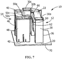
FIG. 7 is a perspective view similar toFIG. 5 , with the first housing and a second housing of the electrical connector mated with the mating electrical component. - The description of illustrative embodiments according to principles of the present invention is intended to be read in connection with the accompanying drawings, which are to be considered part of the entire written description. In the description of embodiments of the invention disclosed herein, any reference to direction or orientation is merely intended for convenience of description and is not intended in any way to limit the scope of the present invention. Relative terms such as "lower," "upper," "horizontal," "vertical," "above," "below," "up," "down," "top" and "bottom" as well as derivative thereof (e.g., "horizontally," "downwardly," "upwardly," etc.) should be construed to refer to the orientation as then described or as shown in the drawing under discussion. These relative terms are for convenience of description only and do not require that the apparatus be constructed or operated in a particular orientation unless explicitly indicated as such. Terms such as "attached," "affixed," "connected," "coupled," "interconnected," and similar refer to a relationship wherein structures are secured or attached to one another either directly or indirectly through intervening structures, as well as both movable or rigid attachments or relationships, unless expressly described otherwise.
- Moreover, the features and benefits of the invention are illustrated by reference to the preferred embodiments. Accordingly, the invention expressly should not be limited to such embodiments illustrating some possible nonlimiting combination of features that may exist alone or in other combinations of features, the scope of the invention being defined by the claims appended hereto.
- As shown in
FIGS. 1 and 2 ,electrical connector 10 has afirst housing 12 and asecond housing 14. Thefirst housing 12 is spaced from thesecond housing 14. - The
first housing 12 has amating face 20 and an oppositely facing wire orcable receiving face 22. Afirst side wall 24 and asecond side wall 26 extend between themating face 20 and thecable receiving face 22.End walls 28 extend between themating face 20 and thecable receiving face 22 and between thefirst side wall 24 and thesecond side wall 26. One or more terminal receivingcavities mating face 20 and thecable receiving face 22. Theterminal receiving cavities terminals FIG. 2 ) therein. The terminals may be of various configurations, including, but not limited to male terminals and female terminals. Other configurations of thefirst housing 12 may be used without departing from the scope of the invention. - In the illustrative embodiment shown, the
housing 12 has a generally L-shaped configuration, with thefirst side wall 24 having a recess section or recess 34 provided therein. In the embodiment shown, variousterminal receiving cavities first housing 12. However, other configurations may be used. - The
second housing 14 has amating face 40 and an oppositely facing wire orcable receiving face 42. Afirst side wall 44 and asecond side wall 46 extend between themating face 40 and thecable receiving face 42.End walls 48 extend between themating face 40 and thecable receiving face 42 and between thefirst side wall 44 and thesecond side wall 46. One or more terminal receivingcavities mating face 40 and thecable receiving face 42. The terminal receivingcavities cavities cavities terminals FIG. 2 ) therein. The terminals may be of various configurations, including, but not limited to male terminals and female terminals. Other configurations of thesecond housing 14 may be used without departing from the scope of the invention. - In the illustrative embodiment shown, the
housing 14 has a generally L-shaped configuration, with thefirst side wall 44 having a recess section orrecess 54 provided therein. In the embodiment shown, various terminal receivingcavities second housing 14. However, other configurations may be used. - One or more flexible joining
member 60 extends between thefirst housing 12 and thesecond housing 14. As shown inFIG. 3 , the flexible joiningmember 60 has a general U-shape with afirst leg 62, asecond leg 64 and anarcuate portion 66 extending between thefirst leg 62 and thesecond leg 64. Thefirst leg 62 is attached to thefirst side wall 24 of thefirst housing 12. Thesecond leg 64 is attached to thefirst side wall 44 of thesecond housing 14. Other configurations of the flexible joiningmember 60 may be used without departing from the scope of the invention. - In the embodiment shown, the
top surface 58 of thearcuate portion 66 of the flexible joiningmember 60 is positioned below the planes of thecable receiving face 22 of thefirst housing 12 and thecable receiving face 42 of thesecond housing 14. In addition, thefirst leg 62 and thesecond leg 64 of the flexible joiningmember 60 are positioned above the planes of thecable receiving face 22 of thefirst housing 12 and thecable receiving face 42 of thesecond housing 14. Consequently, the flexible joiningmember 60 does not extend beyond the planes of thecable receiving face 22 and thecable receiving face 42 or the planes of themating face 20 of thefirst housing 12 and themating face 40 of thesecond housing 14. - In the illustrative embodiment shown the
first housing 12, thesecond housing 14 and the flexible joiningmember 60 are molded as one piece with the flexible joiningmember 60 molded in the U-shape shown. However, other configurations of the flexible joiningmember 60 may be used. In addition, in alternate illustrative embodiments, the flexible joiningmember 60 may be multiple members which are fixed to thefirst housing 12 and thesecond housing 12 using known methods of attachment. - When molded or assembled, the
first housing 12 and thesecond housing 14 are positioned in side-by-side relationship, with the flexible joiningmember 60 extending therebetween. In the initial position, as shown inFIGS. 1 through 4 , themating face 20 of thefirst housing 12 and themating face 40 of thesecond housing 40 are positioned in essentially the same plane. In this position, the flexible joiningmember 60 is in an initial, unstressed position. Consequently, in the initial, unstressed position, the flexible joiningmember 60 does not exert force on thefirst housing 12 or thesecond housing 14, allowing thefirst housing 12 and thesecond housing 14 to remain in position. - The flexible joining
member 60 is configured to have a thickness which allows thearcuate portions 66 to flex or resiliently deform without breaking. The particular thickness of the flexible joiningmember 60, the type of material used and the modulus of elasticity thereof are selected appropraitely. In addition, aslot 67 is provided in thearcuate portion 66 to allow eachportion 69 of thearcuate portion 66 to move independently, providing additional flexibility to the flexible joiningmember 60. - In use, the molded or assembled
electrical connector 10 is moved into engagement with a matingelectrical component 70, as shown inFIGS. 4 through 7 . In the illustrative embodiment shown, the matingelectrical component 70 is a substrate withterminals 72 extending therefrom. However, other configurations of the matingelectrical component 70 may be used. - As shown in
FIG. 4 , theelectrical connector 10 is initially moved into position proximate the matingelectrical component 70. In this position, theelectrical connector 10 is in the initial position, as previously described, with themating face 20 of thefirst housing 12 and themating face 40 of thesecond housing 40 are positioned in essentially the same plane and the flexible joiningmember 60 is in the unstressed position. - With the
electrical connector 10 moved proximate theterminals 72 of the matingelectrical component 70, one of thehousing electrical component 70. In the illustrative embodiment shown inFIGS. 5 and 6 , thefirst housing 12 is moved toward the mating electrical component. - As this occurs, the
terminals 72 are moved through themating face 20 of thefirst housing 12 into the terminal receivingcavities terminals 72 are moved into mechanical and electrical engagement with theterminals first housing 12. The force required to mate thefirst housing 12 matingelectrical component 70 is a result of the engagement of the terminals of thefirst housing 12 with theterminals 72 of the matingelectrical component 70. The force needed to mate thefirst housing 12 with themating component 70 is often applied by the user or operator to thecable receiving face 22 or theend walls 28. - As a force is applied to the
first housing 12 to move the first housing into engagement with the matingelectrical component 70, thefirst housing 12 is moved toward the matingelectrical component 70. However, as no force is applied to thesecond housing 14, thefirst housing 12 is moved relative to thesecond housing 14. As this occurs, the flexible joiningmember 60 is flexed or stressed. As thefirst housing 12 is moved, thefirst leg 62 of the flexible joiningmember 60, which is attached to thefirst housing 12, is moved accordingly. This movement of thefirst leg 62 causes portions of thearcuate portion 66 proximate to thefirst leg 62 to be moved or resiliently deformed in the same direction as the movement of thefirst leg 62 and thefirst housing 12. - With the
first housing 12 properly inserted onto the matingelectrical component 70, thesecond housing 14 is moved toward the mating electrical component to the position shown inFIG. 7 . As this occurs, theterminals 72 are moved through themating face 40 of thesecond housing 14 into the terminal receivingcavities terminals 72 are moved into mechanical and electrical engagement with theterminals second housing 14. The force required to mate thesecond housing 14 to the matingelectrical component 70 is a result of the engagement of the terminals of thesecond housing 14 with theterminals 72 of the matingelectrical component 70. The force needed to mate thesecond housing 14 with themating component 70 is often applied by the user or operator to thecable receiving face 42 or theend walls 48. - As
second housing 14 is mated to the matingelectrical component 70, the flexible joiningmember 60, which is provided in a stressed position after thefirst housing 12 has been mated to the matingelectrical component 70, provides additional force to facilitate the mating of thesecond housing 14. The force is supplied by the resilient movement of thearcuate portion 66 from the stressed position to the unstressed position as thesecond housing 14 is moved toward the matingelectrical component 70 transferring force to thesecond leg 64 and to thesecond housing 14. - As the
electrical connector 10 has thefirst housing 12 which is separate from thesecond housing 14, but connected with flexible joiningmember 60, thefirst housing 12 and thesecond housing 14 can be mated independently to the matingelectrical connector 70. This reduces allows the mating forces needed to mate theelectrical connector 10 to be divided into two components which act independently. Consequently, the mating force needed to mate theelectrical connector 10 to the matingelectrical component 70 is reduced compared to an electrical connector in which all of the contacts are mated to the mating electrical component at the same time. This allows for the mating to be done in a more ergonomic and user friendly manner for the user or operator. - While the invention has been described with reference to a preferred embodiment, it will be understood by those skilled in the art that various changes may be made and equivalents may be substituted for elements thereof without departing from the scope of the invention as defined in the accompanying claims. One skilled in the art will appreciate that the invention may be used with many modifications of structure, arrangement, proportions, sizes, materials and components and otherwise used in the practice of the invention, which are particularly adapted to specific environments and operative requirements without departing from the principles of the present invention. The presently disclosed embodiments are therefore to be considered in all respects as illustrative and not restrictive, the scope of the invention being defined by the appended claims, and not limited to the foregoing description or embodiments.
Claims (20)
- An electrical connector (10) comprising:a first housing (12) having a first mating face (20) and a first cable receiving face (22) with at least one first terminal receiving cavity (30a, 30b, 30c) extending from the first cable receiving face (22) to the first mating face (20);a second housing (14) have a second mating face (40) and a second cable receiving face (42) with at least one second terminal receiving cavity (50a, 50b, 50c) extending from the second cable receiving face (42) to the second mating face (40), the second housing (14) being spaced from the first housing (12),a flexible joining member (60) extending from the first housing (12) to the second housing (14), the flexible joining member (60) configured to allow the first housing (12) to move independently of the second housing (14) as the electrical connector (10) is mounted to an electrical component (70);wherein the first housing (12) can be mated independently to the electrical component (70) from the second housing (14).
- The electrical connector (10) as recited in claim 1, wherein the first mating face (20) of the first housing (12) and the second mating face (40) of the second housing (14) are oriented in the same direction.
- The electrical connector (10) as recited in claim 1 or 2, wherein the first cable receiving face (22) of the first housing (12) and the second cable receiving face (42) of the second housing (14) are oriented in the same direction.
- The electrical connector (10) as recited in any preceding claim, wherein the flexible joining member (60) is integrally molded to the first housing (12) and the second housing (14).
- The electrical connector (10) as recited in any preceding claim, wherein the flexible joining member (60) is a U-shaped member with a first leg (62), a second leg (64) and an arcuate portion (66) extending between the first leg (62) and the second leg (64), the first leg (62) is attached to the first housing (12) and the second leg (64) is attached to the second housing (14).
- The electrical connector (10)as recited in claim 5, wherein the first leg (62) of the flexible joining member (60) extends from a first side surface of the first housing (12).
- The electrical connector (10) as recited in claim 6, where the second leg (64) of the flexible joining member (60) extends from a second side surface of the second housing (14).
- The electrical connector (10) as recited in any preceding claim, wherein the first housing (12) has a first L-shaped configuration and the second housing (14) has a second L-shaped configuration, the first housing (12) and the second housing (14) forming a cavity in which the flexible joining member (60) is positioned.
- An electrical connector (10) for mating to a mating electrical component (70), the electrical connector (10) comprising:a first housing (12) having a first mating face (20);a second housing (14) have a second mating face (40), the second housing (14) being spaced from the first housing (12),a flexible joining member (60) integrally molded with the first housing (12) and the second housing (14), the flexible joining member (60) extending from the first housing (12) to the second housing (14), the flexible joining member (60) configured to allow the first housing (12) to move independently of the second housing (14);wherein the first housing (12) can be mated independently to the mating electrical component (70) from the second housing (14).
- The electrical connector (10) as recited in claim 9, wherein the flexible joining member (60) is a U-shaped member with a first leg (62), a second leg (64) and an arcuate portion (66) extending between the first leg (62) and the second leg (64), the first leg (62) is attached to the first housing (12) and the second leg (64) is attached to the second housing (14).
- The electrical connector (10) as recited in claim 10, wherein the first leg (62) of the flexible joining member (60) extends from a first side surface of the first housing (12).
- The electrical connector (10) as recited in claim 11, where the second leg (64) of the flexible joining member (60) extends from a second side surface of the second housing (14).
- The electrical connector (10) as recited in claim 12, wherein the first housing (12) has a first L-shaped configuration and the second housing (14) has a second L-shaped configuration, the first housing (12) and the second housing (14) forming a cavity between the first side surface and the second side surface in which the flexible joining member (60) is positioned.
- The electrical connector (10) as recited in any of claims 9 to 13, wherein the first mating face (20) of the first housing (12) and the second mating face (40) of the second housing (14) are oriented in the same direction.
- An electrical connector (10) for mating to a mating electrical component (70), the electrical connector (10) comprising:a first housing (12) having a first mating face (20), the first housing (12) having a first recess provided in a first side wall of the first housing (12);a second housing (14) having a second mating face (40), the second housing (14) having a second recess provided in a second side wall of the second housing (14), the second housing (14) being spaced from the first housing (12) with the first recess facing the second recess;a flexible joining member (60) positioned in the first recess and the second recess, the flexible joining member (60) extending from the first housing (12) to the second housing (14), the flexible joining member (60) configured to allow the first housing (12) to move independently of the second housing (14);wherein the first housing (12) can be mated independently to the mating electrical component (70) from the second housing (14).
- The electrical connector (10) as recited in claim 15, wherein the first mating face (20) of the first housing (12) and the second mating face (40) of the second housing (14) are oriented in the same direction.
- The electrical connector (10) as recited in claim 15 or 16, wherein the flexible joining member (60) is a U-shaped member with a first leg (62), a second leg (64) and an arcuate portion (66) extending between the first leg (62) and the second leg (64), the first leg (62) is attached to the first housing (12) and the second leg (64) is attached to the second housing.
- The electrical connector (10) as recited in claim 15, 16 or 17, wherein the flexible joining member (60) is integrally molded to the first housing (12) and the second housing (14).
- The electrical connector (10) as recited in claim 17 or 18, wherein the first leg (62) of the flexible joining member (60) extends from a first side surface of the first housing (12) and the second leg (64) of the flexible joining member (60) extends from a second side surface of the second housing (14).
- The electrical connector (10) as recited in any of claims 19, wherein the first housing (12) has a first L-shaped configuration and the second housing (14) has a second L-shaped configuration.
Applications Claiming Priority (1)
| Application Number | Priority Date | Filing Date | Title |
|---|---|---|---|
| US17/333,756 US11621514B2 (en) | 2021-05-28 | 2021-05-28 | Electrical connector with connector housing joined by a flexible joining member |
Publications (1)
| Publication Number | Publication Date |
|---|---|
| EP4096025A1 true EP4096025A1 (en) | 2022-11-30 |
Family
ID=81851655
Family Applications (1)
| Application Number | Title | Priority Date | Filing Date |
|---|---|---|---|
| EP22175955.8A Pending EP4096025A1 (en) | 2021-05-28 | 2022-05-27 | Electrical connector with connector housing joined by a flexible joining member |
Country Status (3)
| Country | Link |
|---|---|
| US (1) | US11621514B2 (en) |
| EP (1) | EP4096025A1 (en) |
| CN (1) | CN115411558A (en) |
Families Citing this family (1)
| Publication number | Priority date | Publication date | Assignee | Title |
|---|---|---|---|---|
| US11804667B2 (en) * | 2021-07-22 | 2023-10-31 | Te Connectivity Solutions Gmbh | Board-to-board connector assembly for add-in cards |
Citations (4)
| Publication number | Priority date | Publication date | Assignee | Title |
|---|---|---|---|---|
| FR2458919A1 (en) * | 1979-06-05 | 1981-01-02 | Carpano & Pons | Multiple connector comprising insulating modular parts - which are interlinked for positioning but may be separately connected for maintenance |
| US20140078664A1 (en) * | 2012-09-14 | 2014-03-20 | Michael Chi Kin Lau | Computer component connector |
| US20170170588A1 (en) * | 2015-12-15 | 2017-06-15 | Hirose Electric Co., Ltd. | Electrical connector |
| US20200112114A1 (en) * | 2018-10-09 | 2020-04-09 | TE Connectivity Italia Distribution S.r.l. | Connection Device |
Family Cites Families (3)
| Publication number | Priority date | Publication date | Assignee | Title |
|---|---|---|---|---|
| US5521803A (en) * | 1994-08-05 | 1996-05-28 | Eckert; Lee H. | Flashlight with flexible core |
| US11114803B2 (en) * | 2019-05-31 | 2021-09-07 | Molex, Llc | Connector system with wafers |
| US12021330B2 (en) * | 2021-02-11 | 2024-06-25 | Te Connectivity Solutions Gmbh | Connector with a mating assistance assembly |
-
2021
- 2021-05-28 US US17/333,756 patent/US11621514B2/en active Active
-
2022
- 2022-05-26 CN CN202210581686.2A patent/CN115411558A/en active Pending
- 2022-05-27 EP EP22175955.8A patent/EP4096025A1/en active Pending
Patent Citations (4)
| Publication number | Priority date | Publication date | Assignee | Title |
|---|---|---|---|---|
| FR2458919A1 (en) * | 1979-06-05 | 1981-01-02 | Carpano & Pons | Multiple connector comprising insulating modular parts - which are interlinked for positioning but may be separately connected for maintenance |
| US20140078664A1 (en) * | 2012-09-14 | 2014-03-20 | Michael Chi Kin Lau | Computer component connector |
| US20170170588A1 (en) * | 2015-12-15 | 2017-06-15 | Hirose Electric Co., Ltd. | Electrical connector |
| US20200112114A1 (en) * | 2018-10-09 | 2020-04-09 | TE Connectivity Italia Distribution S.r.l. | Connection Device |
Also Published As
| Publication number | Publication date |
|---|---|
| US11621514B2 (en) | 2023-04-04 |
| US20220384982A1 (en) | 2022-12-01 |
| CN115411558A (en) | 2022-11-29 |
Similar Documents
| Publication | Publication Date | Title |
|---|---|---|
| US8083527B2 (en) | Board-to-board connector | |
| US7731520B1 (en) | Blade and receptacle power connector | |
| US8827724B2 (en) | Board connector | |
| JP2580357B2 (en) | Electrical connector | |
| US7422465B2 (en) | Electrical connector having flexible mating portion | |
| CN107134672B (en) | Connector with a locking member | |
| US7273397B2 (en) | Electrical connector having flexible mating portion | |
| JPH08273760A (en) | Lock type electric connector | |
| CN106981754B (en) | Connector | |
| JP2617157B2 (en) | Female electrical terminal | |
| CN1301065A (en) | Connectors with improved guiding parts | |
| JP2000311738A (en) | Electrical contacts | |
| CN104253337A (en) | Connector, and header and socket included in the same | |
| TWI700867B (en) | Connector and connector assembly | |
| EP4096024B1 (en) | Low insertion force contact terminal | |
| CN110534969A (en) | Electrical connector and connector combination with the electrical connector | |
| CN212323275U (en) | Floating connector | |
| JP2006339154A (en) | Connector having lock lever | |
| CN115377719A (en) | Terminal, wire connector and wire-to-board connector | |
| US11621514B2 (en) | Electrical connector with connector housing joined by a flexible joining member | |
| US20100304587A1 (en) | Connector cover | |
| CN112886324A (en) | Electrical connection device | |
| CN212033278U (en) | Connector with a locking member | |
| CN212626388U (en) | Electrical connectors and electronic equipment | |
| JP7608276B2 (en) | Connector and connector assembly |
Legal Events
| Date | Code | Title | Description |
|---|---|---|---|
| PUAI | Public reference made under article 153(3) epc to a published international application that has entered the european phase |
Free format text: ORIGINAL CODE: 0009012 |
|
| STAA | Information on the status of an ep patent application or granted ep patent |
Free format text: STATUS: THE APPLICATION HAS BEEN PUBLISHED |
|
| AK | Designated contracting states |
Kind code of ref document: A1 Designated state(s): AL AT BE BG CH CY CZ DE DK EE ES FI FR GB GR HR HU IE IS IT LI LT LU LV MC MK MT NL NO PL PT RO RS SE SI SK SM TR |
|
| STAA | Information on the status of an ep patent application or granted ep patent |
Free format text: STATUS: REQUEST FOR EXAMINATION WAS MADE |
|
| 17P | Request for examination filed |
Effective date: 20230525 |
|
| RBV | Designated contracting states (corrected) |
Designated state(s): AL AT BE BG CH CY CZ DE DK EE ES FI FR GB GR HR HU IE IS IT LI LT LU LV MC MK MT NL NO PL PT RO RS SE SI SK SM TR |
|
| STAA | Information on the status of an ep patent application or granted ep patent |
Free format text: STATUS: EXAMINATION IS IN PROGRESS |
|
| 17Q | First examination report despatched |
Effective date: 20241104 |