EP4095997A1 - Thermally efficient pouch cell architecture - Google Patents
Thermally efficient pouch cell architecture Download PDFInfo
- Publication number
- EP4095997A1 EP4095997A1 EP22166226.5A EP22166226A EP4095997A1 EP 4095997 A1 EP4095997 A1 EP 4095997A1 EP 22166226 A EP22166226 A EP 22166226A EP 4095997 A1 EP4095997 A1 EP 4095997A1
- Authority
- EP
- European Patent Office
- Prior art keywords
- cathode
- anode
- electrode
- cathodes
- separator film
- Prior art date
- Legal status (The legal status is an assumption and is not a legal conclusion. Google has not performed a legal analysis and makes no representation as to the accuracy of the status listed.)
- Pending
Links
- 239000010405 anode material Substances 0.000 claims abstract description 36
- 239000010406 cathode material Substances 0.000 claims abstract description 36
- 239000007772 electrode material Substances 0.000 claims description 16
- 238000000034 method Methods 0.000 claims description 15
- 229910000625 lithium cobalt oxide Inorganic materials 0.000 claims description 12
- BFZPBUKRYWOWDV-UHFFFAOYSA-N lithium;oxido(oxo)cobalt Chemical compound [Li+].[O-][Co]=O BFZPBUKRYWOWDV-UHFFFAOYSA-N 0.000 claims description 12
- OKTJSMMVPCPJKN-UHFFFAOYSA-N Carbon Chemical compound [C] OKTJSMMVPCPJKN-UHFFFAOYSA-N 0.000 claims description 6
- 239000010439 graphite Substances 0.000 claims description 6
- 229910002804 graphite Inorganic materials 0.000 claims description 6
- 238000005452 bending Methods 0.000 claims description 4
- 238000010586 diagram Methods 0.000 description 14
- -1 silicon oxide aluminum Chemical compound 0.000 description 7
- 239000003792 electrolyte Substances 0.000 description 5
- 229920000642 polymer Polymers 0.000 description 5
- 229910001416 lithium ion Inorganic materials 0.000 description 4
- 239000000463 material Substances 0.000 description 4
- 238000003466 welding Methods 0.000 description 4
- HBBGRARXTFLTSG-UHFFFAOYSA-N Lithium ion Chemical compound [Li+] HBBGRARXTFLTSG-UHFFFAOYSA-N 0.000 description 3
- 239000004020 conductor Substances 0.000 description 3
- 238000003860 storage Methods 0.000 description 3
- RYGMFSIKBFXOCR-UHFFFAOYSA-N Copper Chemical compound [Cu] RYGMFSIKBFXOCR-UHFFFAOYSA-N 0.000 description 2
- WHXSMMKQMYFTQS-UHFFFAOYSA-N Lithium Chemical compound [Li] WHXSMMKQMYFTQS-UHFFFAOYSA-N 0.000 description 2
- 239000000853 adhesive Substances 0.000 description 2
- 230000001070 adhesive effect Effects 0.000 description 2
- 229910052782 aluminium Inorganic materials 0.000 description 2
- XAGFODPZIPBFFR-UHFFFAOYSA-N aluminium Chemical compound [Al] XAGFODPZIPBFFR-UHFFFAOYSA-N 0.000 description 2
- 230000008901 benefit Effects 0.000 description 2
- 238000005229 chemical vapour deposition Methods 0.000 description 2
- 229910052802 copper Inorganic materials 0.000 description 2
- 239000010949 copper Substances 0.000 description 2
- 238000002788 crimping Methods 0.000 description 2
- 238000011161 development Methods 0.000 description 2
- 238000009826 distribution Methods 0.000 description 2
- 238000005342 ion exchange Methods 0.000 description 2
- 229910052744 lithium Inorganic materials 0.000 description 2
- GELKBWJHTRAYNV-UHFFFAOYSA-K lithium iron phosphate Chemical compound [Li+].[Fe+2].[O-]P([O-])([O-])=O GELKBWJHTRAYNV-UHFFFAOYSA-K 0.000 description 2
- 229910001496 lithium tetrafluoroborate Inorganic materials 0.000 description 2
- 238000012986 modification Methods 0.000 description 2
- 230000004048 modification Effects 0.000 description 2
- 238000005240 physical vapour deposition Methods 0.000 description 2
- 238000000623 plasma-assisted chemical vapour deposition Methods 0.000 description 2
- 238000005476 soldering Methods 0.000 description 2
- OIFBSDVPJOWBCH-UHFFFAOYSA-N Diethyl carbonate Chemical compound CCOC(=O)OCC OIFBSDVPJOWBCH-UHFFFAOYSA-N 0.000 description 1
- KMTRUDSVKNLOMY-UHFFFAOYSA-N Ethylene carbonate Chemical compound O=C1OCCO1 KMTRUDSVKNLOMY-UHFFFAOYSA-N 0.000 description 1
- DGAQECJNVWCQMB-PUAWFVPOSA-M Ilexoside XXIX Chemical compound C[C@@H]1CC[C@@]2(CC[C@@]3(C(=CC[C@H]4[C@]3(CC[C@@H]5[C@@]4(CC[C@@H](C5(C)C)OS(=O)(=O)[O-])C)C)[C@@H]2[C@]1(C)O)C)C(=O)O[C@H]6[C@@H]([C@H]([C@@H]([C@H](O6)CO)O)O)O.[Na+] DGAQECJNVWCQMB-PUAWFVPOSA-M 0.000 description 1
- 229910000552 LiCF3SO3 Inorganic materials 0.000 description 1
- 229910010710 LiFePO Inorganic materials 0.000 description 1
- 229910052493 LiFePO4 Inorganic materials 0.000 description 1
- 229910001290 LiPF6 Inorganic materials 0.000 description 1
- 239000004698 Polyethylene Substances 0.000 description 1
- 239000004743 Polypropylene Substances 0.000 description 1
- XUIMIQQOPSSXEZ-UHFFFAOYSA-N Silicon Chemical compound [Si] XUIMIQQOPSSXEZ-UHFFFAOYSA-N 0.000 description 1
- ATJFFYVFTNAWJD-UHFFFAOYSA-N Tin Chemical compound [Sn] ATJFFYVFTNAWJD-UHFFFAOYSA-N 0.000 description 1
- 230000009286 beneficial effect Effects 0.000 description 1
- OJIJEKBXJYRIBZ-UHFFFAOYSA-N cadmium nickel Chemical compound [Ni].[Cd] OJIJEKBXJYRIBZ-UHFFFAOYSA-N 0.000 description 1
- 238000000576 coating method Methods 0.000 description 1
- 238000001816 cooling Methods 0.000 description 1
- 238000005137 deposition process Methods 0.000 description 1
- 238000007599 discharging Methods 0.000 description 1
- 238000004146 energy storage Methods 0.000 description 1
- PCHJSUWPFVWCPO-UHFFFAOYSA-N gold Chemical compound [Au] PCHJSUWPFVWCPO-UHFFFAOYSA-N 0.000 description 1
- 229910052737 gold Inorganic materials 0.000 description 1
- 239000010931 gold Substances 0.000 description 1
- 230000020169 heat generation Effects 0.000 description 1
- 239000011810 insulating material Substances 0.000 description 1
- 239000011344 liquid material Substances 0.000 description 1
- MHCFAGZWMAWTNR-UHFFFAOYSA-M lithium perchlorate Chemical compound [Li+].[O-]Cl(=O)(=O)=O MHCFAGZWMAWTNR-UHFFFAOYSA-M 0.000 description 1
- CJYZTOPVWURGAI-UHFFFAOYSA-N lithium;manganese;manganese(3+);oxygen(2-) Chemical compound [Li+].[O-2].[O-2].[O-2].[O-2].[Mn].[Mn+3] CJYZTOPVWURGAI-UHFFFAOYSA-N 0.000 description 1
- VROAXDSNYPAOBJ-UHFFFAOYSA-N lithium;oxido(oxo)nickel Chemical compound [Li+].[O-][Ni]=O VROAXDSNYPAOBJ-UHFFFAOYSA-N 0.000 description 1
- MCVFFRWZNYZUIJ-UHFFFAOYSA-M lithium;trifluoromethanesulfonate Chemical compound [Li+].[O-]S(=O)(=O)C(F)(F)F MCVFFRWZNYZUIJ-UHFFFAOYSA-M 0.000 description 1
- 229910001092 metal group alloy Inorganic materials 0.000 description 1
- 229910052987 metal hydride Inorganic materials 0.000 description 1
- 230000008520 organization Effects 0.000 description 1
- 230000037361 pathway Effects 0.000 description 1
- 229920000573 polyethylene Polymers 0.000 description 1
- 229920000098 polyolefin Polymers 0.000 description 1
- 229920001155 polypropylene Polymers 0.000 description 1
- 230000008569 process Effects 0.000 description 1
- 238000011160 research Methods 0.000 description 1
- 229910052710 silicon Inorganic materials 0.000 description 1
- 239000010703 silicon Substances 0.000 description 1
- 229910052708 sodium Inorganic materials 0.000 description 1
- 239000011734 sodium Substances 0.000 description 1
- 239000007784 solid electrolyte Substances 0.000 description 1
- 238000012546 transfer Methods 0.000 description 1
Images

Classifications
-
- H—ELECTRICITY
- H01—ELECTRIC ELEMENTS
- H01M—PROCESSES OR MEANS, e.g. BATTERIES, FOR THE DIRECT CONVERSION OF CHEMICAL ENERGY INTO ELECTRICAL ENERGY
- H01M50/00—Constructional details or processes of manufacture of the non-active parts of electrochemical cells other than fuel cells, e.g. hybrid cells
- H01M50/50—Current conducting connections for cells or batteries
- H01M50/502—Interconnectors for connecting terminals of adjacent batteries; Interconnectors for connecting cells outside a battery casing
- H01M50/507—Interconnectors for connecting terminals of adjacent batteries; Interconnectors for connecting cells outside a battery casing comprising an arrangement of two or more busbars within a container structure, e.g. busbar modules
-
- H—ELECTRICITY
- H01—ELECTRIC ELEMENTS
- H01M—PROCESSES OR MEANS, e.g. BATTERIES, FOR THE DIRECT CONVERSION OF CHEMICAL ENERGY INTO ELECTRICAL ENERGY
- H01M10/00—Secondary cells; Manufacture thereof
- H01M10/04—Construction or manufacture in general
- H01M10/0459—Cells or batteries with folded separator between plate-like electrodes
-
- H—ELECTRICITY
- H01—ELECTRIC ELEMENTS
- H01M—PROCESSES OR MEANS, e.g. BATTERIES, FOR THE DIRECT CONVERSION OF CHEMICAL ENERGY INTO ELECTRICAL ENERGY
- H01M10/00—Secondary cells; Manufacture thereof
- H01M10/04—Construction or manufacture in general
-
- H—ELECTRICITY
- H01—ELECTRIC ELEMENTS
- H01M—PROCESSES OR MEANS, e.g. BATTERIES, FOR THE DIRECT CONVERSION OF CHEMICAL ENERGY INTO ELECTRICAL ENERGY
- H01M10/00—Secondary cells; Manufacture thereof
- H01M10/05—Accumulators with non-aqueous electrolyte
- H01M10/052—Li-accumulators
- H01M10/0525—Rocking-chair batteries, i.e. batteries with lithium insertion or intercalation in both electrodes; Lithium-ion batteries
-
- H—ELECTRICITY
- H01—ELECTRIC ELEMENTS
- H01M—PROCESSES OR MEANS, e.g. BATTERIES, FOR THE DIRECT CONVERSION OF CHEMICAL ENERGY INTO ELECTRICAL ENERGY
- H01M10/00—Secondary cells; Manufacture thereof
- H01M10/05—Accumulators with non-aqueous electrolyte
- H01M10/058—Construction or manufacture
- H01M10/0583—Construction or manufacture of accumulators with folded construction elements except wound ones, i.e. folded positive or negative electrodes or separators, e.g. with "Z"-shaped electrodes or separators
-
- H—ELECTRICITY
- H01—ELECTRIC ELEMENTS
- H01M—PROCESSES OR MEANS, e.g. BATTERIES, FOR THE DIRECT CONVERSION OF CHEMICAL ENERGY INTO ELECTRICAL ENERGY
- H01M10/00—Secondary cells; Manufacture thereof
- H01M10/05—Accumulators with non-aqueous electrolyte
- H01M10/058—Construction or manufacture
- H01M10/0585—Construction or manufacture of accumulators having only flat construction elements, i.e. flat positive electrodes, flat negative electrodes and flat separators
-
- H—ELECTRICITY
- H01—ELECTRIC ELEMENTS
- H01M—PROCESSES OR MEANS, e.g. BATTERIES, FOR THE DIRECT CONVERSION OF CHEMICAL ENERGY INTO ELECTRICAL ENERGY
- H01M4/00—Electrodes
- H01M4/02—Electrodes composed of, or comprising, active material
- H01M4/36—Selection of substances as active materials, active masses, active liquids
- H01M4/48—Selection of substances as active materials, active masses, active liquids of inorganic oxides or hydroxides
- H01M4/52—Selection of substances as active materials, active masses, active liquids of inorganic oxides or hydroxides of nickel, cobalt or iron
- H01M4/525—Selection of substances as active materials, active masses, active liquids of inorganic oxides or hydroxides of nickel, cobalt or iron of mixed oxides or hydroxides containing iron, cobalt or nickel for inserting or intercalating light metals, e.g. LiNiO2, LiCoO2 or LiCoOxFy
-
- H—ELECTRICITY
- H01—ELECTRIC ELEMENTS
- H01M—PROCESSES OR MEANS, e.g. BATTERIES, FOR THE DIRECT CONVERSION OF CHEMICAL ENERGY INTO ELECTRICAL ENERGY
- H01M4/00—Electrodes
- H01M4/02—Electrodes composed of, or comprising, active material
- H01M4/36—Selection of substances as active materials, active masses, active liquids
- H01M4/58—Selection of substances as active materials, active masses, active liquids of inorganic compounds other than oxides or hydroxides, e.g. sulfides, selenides, tellurides, halogenides or LiCoFy; of polyanionic structures, e.g. phosphates, silicates or borates
- H01M4/583—Carbonaceous material, e.g. graphite-intercalation compounds or CFx
- H01M4/587—Carbonaceous material, e.g. graphite-intercalation compounds or CFx for inserting or intercalating light metals
-
- H—ELECTRICITY
- H01—ELECTRIC ELEMENTS
- H01M—PROCESSES OR MEANS, e.g. BATTERIES, FOR THE DIRECT CONVERSION OF CHEMICAL ENERGY INTO ELECTRICAL ENERGY
- H01M50/00—Constructional details or processes of manufacture of the non-active parts of electrochemical cells other than fuel cells, e.g. hybrid cells
- H01M50/10—Primary casings; Jackets or wrappings
- H01M50/102—Primary casings; Jackets or wrappings characterised by their shape or physical structure
- H01M50/105—Pouches or flexible bags
-
- H—ELECTRICITY
- H01—ELECTRIC ELEMENTS
- H01M—PROCESSES OR MEANS, e.g. BATTERIES, FOR THE DIRECT CONVERSION OF CHEMICAL ENERGY INTO ELECTRICAL ENERGY
- H01M50/00—Constructional details or processes of manufacture of the non-active parts of electrochemical cells other than fuel cells, e.g. hybrid cells
- H01M50/20—Mountings; Secondary casings or frames; Racks, modules or packs; Suspension devices; Shock absorbers; Transport or carrying devices; Holders
- H01M50/204—Racks, modules or packs for multiple batteries or multiple cells
- H01M50/207—Racks, modules or packs for multiple batteries or multiple cells characterised by their shape
- H01M50/211—Racks, modules or packs for multiple batteries or multiple cells characterised by their shape adapted for pouch cells
-
- H—ELECTRICITY
- H01—ELECTRIC ELEMENTS
- H01M—PROCESSES OR MEANS, e.g. BATTERIES, FOR THE DIRECT CONVERSION OF CHEMICAL ENERGY INTO ELECTRICAL ENERGY
- H01M50/00—Constructional details or processes of manufacture of the non-active parts of electrochemical cells other than fuel cells, e.g. hybrid cells
- H01M50/50—Current conducting connections for cells or batteries
- H01M50/502—Interconnectors for connecting terminals of adjacent batteries; Interconnectors for connecting cells outside a battery casing
- H01M50/509—Interconnectors for connecting terminals of adjacent batteries; Interconnectors for connecting cells outside a battery casing characterised by the type of connection, e.g. mixed connections
-
- H—ELECTRICITY
- H01—ELECTRIC ELEMENTS
- H01M—PROCESSES OR MEANS, e.g. BATTERIES, FOR THE DIRECT CONVERSION OF CHEMICAL ENERGY INTO ELECTRICAL ENERGY
- H01M50/00—Constructional details or processes of manufacture of the non-active parts of electrochemical cells other than fuel cells, e.g. hybrid cells
- H01M50/50—Current conducting connections for cells or batteries
- H01M50/528—Fixed electrical connections, i.e. not intended for disconnection
-
- H—ELECTRICITY
- H01—ELECTRIC ELEMENTS
- H01M—PROCESSES OR MEANS, e.g. BATTERIES, FOR THE DIRECT CONVERSION OF CHEMICAL ENERGY INTO ELECTRICAL ENERGY
- H01M50/00—Constructional details or processes of manufacture of the non-active parts of electrochemical cells other than fuel cells, e.g. hybrid cells
- H01M50/50—Current conducting connections for cells or batteries
- H01M50/531—Electrode connections inside a battery casing
- H01M50/54—Connection of several leads or tabs of plate-like electrode stacks, e.g. electrode pole straps or bridges
-
- H—ELECTRICITY
- H01—ELECTRIC ELEMENTS
- H01M—PROCESSES OR MEANS, e.g. BATTERIES, FOR THE DIRECT CONVERSION OF CHEMICAL ENERGY INTO ELECTRICAL ENERGY
- H01M50/00—Constructional details or processes of manufacture of the non-active parts of electrochemical cells other than fuel cells, e.g. hybrid cells
- H01M50/50—Current conducting connections for cells or batteries
- H01M50/543—Terminals
- H01M50/552—Terminals characterised by their shape
- H01M50/553—Terminals adapted for prismatic, pouch or rectangular cells
-
- Y—GENERAL TAGGING OF NEW TECHNOLOGICAL DEVELOPMENTS; GENERAL TAGGING OF CROSS-SECTIONAL TECHNOLOGIES SPANNING OVER SEVERAL SECTIONS OF THE IPC; TECHNICAL SUBJECTS COVERED BY FORMER USPC CROSS-REFERENCE ART COLLECTIONS [XRACs] AND DIGESTS
- Y02—TECHNOLOGIES OR APPLICATIONS FOR MITIGATION OR ADAPTATION AGAINST CLIMATE CHANGE
- Y02E—REDUCTION OF GREENHOUSE GAS [GHG] EMISSIONS, RELATED TO ENERGY GENERATION, TRANSMISSION OR DISTRIBUTION
- Y02E60/00—Enabling technologies; Technologies with a potential or indirect contribution to GHG emissions mitigation
- Y02E60/10—Energy storage using batteries
-
- Y—GENERAL TAGGING OF NEW TECHNOLOGICAL DEVELOPMENTS; GENERAL TAGGING OF CROSS-SECTIONAL TECHNOLOGIES SPANNING OVER SEVERAL SECTIONS OF THE IPC; TECHNICAL SUBJECTS COVERED BY FORMER USPC CROSS-REFERENCE ART COLLECTIONS [XRACs] AND DIGESTS
- Y02—TECHNOLOGIES OR APPLICATIONS FOR MITIGATION OR ADAPTATION AGAINST CLIMATE CHANGE
- Y02P—CLIMATE CHANGE MITIGATION TECHNOLOGIES IN THE PRODUCTION OR PROCESSING OF GOODS
- Y02P70/00—Climate change mitigation technologies in the production process for final industrial or consumer products
- Y02P70/50—Manufacturing or production processes characterised by the final manufactured product
Definitions
- the present invention relates generally to a system and method for providing a thermally efficient pouch cell battery, and, in particular embodiments, to a system and method for providing a pouch cell battery with full width electrodes that are disposed at opposite ends of the pouch cell battery to provide improved current and heat distribution.
- Cylindrical batteries use two continuous electrodes rolled in a spiral
- pouch cell batteries tend to use multiple electrodes in a stack configuration.
- the pouch cell arrangement provides for greater energy density within given space, the arrangement of the stacked electrodes, particularly for high current drain application, can lead to localized heat buildup in the battery, reducing performance, storage capacity and battery lifetime.
- An embodiment battery includes a separator film, a plurality of cathodes, each cathode of the plurality of cathodes having a cathode base and a cathode material disposed on the cathode base, where a first end of the cathode base of the respective cathode has a cathode connection portion that is free of the cathode material, where the cathode material of the respective cathode extends contiguously across a width of the cathode base of the respective cathode, and further extends contiguously from a second end of the cathode base of the respective cathode opposite the first end to the cathode connection portion of the respective cathode, and where the cathode connection portion of the respective cathode extends contiguously across the width of the cathode base of the respective cathode, a plurality of anodes, each anode of the plurality of anodes having an anode base and an
- An embodiment battery pack includes a plurality of bus bars, and a plurality of cells.
- Each cell includes a separator film, and an electrode stack including a plurality of electrodes, each electrode of the plurality of electrodes having an electrode base and an electrode material disposed on the electrode base, where a first end of the electrode base of the respective electrode has an electrode connection portion that is free of the electrode material, where the electrode material of the respective electrode extends contiguously across a width of the electrode base of the respective electrode, and further extends contiguously from a second end of the electrode base of the respective electrode opposite the first end to the electrode connection portion of the respective electrode, and where the electrode connection portion of the respective cathode extends contiguously across the width of the electrode base of the respective electrode, where adjacent electrodes of the plurality of electrodes are separated from each other by a portion of the separator film, and where first electrode connection portions of a first group of electrodes of the plurality of electrodes extend from between a first edge of the separator film and a second edge of the
- An embodiment method for providing a battery includes providing a separator film, providing a plurality of cathodes, each cathode of the plurality of cathodes having a cathode base and a cathode material disposed on the cathode base, where a first end of the cathode base of the respective cathode has a cathode connection portion that is free of the cathode material, where the cathode material of the respective cathode extends contiguously across a width of the cathode base of the respective cathode, and further extends contiguously from a second end of the cathode base of the respective cathode opposite the first end to the cathode connection portion of the respective cathode, and where the cathode connection portion of the respective cathode extends contiguously across the width of the cathode base of the respective cathode, providing a plurality of anodes, each anode of the plurality of anodes
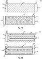
- Fig. 1A is a diagram illustrating electrodes 100 according to some embodiments.
- the electrodes 100 for a battery may include a cathode 102 and anode 112.
- the cathode 102 may have a cathode base 104
- the anode 112 may have an anode base 114 that are each formed from a conductive material such as copper, aluminum, gold, a metallic alloy, or another conductive material.
- the cathode base 104 may be formed from a different material than the anode base 114.
- the cathode base 104 may be copper, while the anode base 114 may be aluminum.
- the cathode base 104 and anode base 114 act as current collectors for the electrodes, allowing movement of current or electrons out of the battery, and providing support for electrode materials 108, 118.
- a cathode material 108 is disposed on the cathode base 104
- an anode material 118 is disposed on the anode base 114.
- the cathode material 108 and anode material 118 may be coatings or layers formed on a portion of the respective cathode base 104 and anode base 114.
- the electrode materials 108, 118 maybe formed by chemical vapor deposition (CVD), physical vapor deposition (PVD), plasma enhanced chemical vapor deposition (PECVD), or another deposition process.
- the electrode material 108, 118 may be deposited on the respective electrode base 104, 114, and cured, sintered, or otherwise affixed to the electrode base 104, 114.
- the battery may be a lithium ion battery (Li-ion) using a lithium based chemistry, where the cathode material 108 is lithium cobalt oxide (LiCoO 2 ), and the anode material 118 is graphite.
- other cathode materials 108 may be used, such as lithium iron phosphate (LiFePO), lithium manganese oxide (LiMn 2 O 4 ), lithium nickel oxide (LiNiO 2 ), or the like.
- the anode material 108 may be a material such as sodium, lithium, silicon, or silicon oxide aluminum, tin, or the like.
- the battery may use chemistry such as a zinc-air, nickel-cadmium (NiCd), nickel-metal hydride (NiMH), lithium iron phosphate (LiFePO 4 ), lithium-ion polymer (Li-ion polymer/LiPo), or the like, with appropriate electrode materials 108, 118.
- the cathode material 108 and anode material 118 may be formed on only a portion of the cathode base 104 and anode base 114, so that the cathode 102 and anode 112 have a cathode contact portion 106 and anode contact portion 116, respectively, without electrode material 108, 118.
- the cathode contact portion 106 and anode contact portion 116 maybe exposed electrode base material or a bare anode or bare cathode that is free of electrode material so that the electrodes 100 may be efficiently electrically connected to other conductive elements.
- the cathode contact portion 106 may disposed at a first end 120 of the cathode base 104, and the cathode material 108 may be disposed at a second end 122 of the cathode base 104, with the cathode material 108 extending from the second end 122 to the cathode contact portion 106.
- the anode contact portion 116 may disposed at a first end 130 of the anode base 114, and the anode material 118 may be disposed at a second end 132 of the anode base 114, with the anode material 118 extending from the second end 132 to the anode contact portion 116.
- the contact portions 106, 116 extend substantially the entire width of the respective electrode 100, which provide for more linear current flow along length of the electrodes 100, and more uniform heat generation in each electrode 100.
- Fig. 1B is a diagram illustrating current flow 140 in the electrodes 100 according to some embodiments.
- the current flow 140 in the cathode 102 is from the second end 122 and from the cathode material 108 to the first end 120 and the cathode contact portion 106.
- the current flow 140 in the anode 112 is from the first end 130 and from the anode contact portion 116 to the second end 132 and into the anode material 118.
- the current density in the cathode 102 and anode 112 is densest nearest the contact portions 106, 116. This results in the greatest heat concentration nearest the contact portions 106, 116 due to the current density.
- contact portions 106, 116 that extend the width of the electrode 100 allows the current being drawn from, or moved into, the electrode material 108, 118 to be spread across the entire width of the electrode 100, rather than concentrated at one corner of an electrode, as when the contact region is a small tab at the end of the electrode. This avoids non-uniform heat buildup associated with of non-uniform current pathways for contact portions that extend only partway across the width of the electrode.
- the electrodes 100 may also be arranged in the battery so that the cathode contact portion 106 is at the opposite end of the battery from the anode contact portion 116.
- This arrangement of the contact portions 106, 116 at opposite ends of the battery permits the contact portions 106, 116 to be exposed outside the battery without the risk of the cathode contact portion 106 inadvertently contacting the anode contact portion 116. This also results in overall cooler operation and more uniform heat distribution, as heat for the different electrode types is concentrated at opposite ends of the battery. Separating the contact portions 106, 116 for opposing electrodes 100 at opposite ends of the batteries also permits the use of simple heat sinks, fins, or a common electric contact plate to pull heat away from the battery.
- the separate contact portions 106, 116 at opposite ends of the battery result in positive and negative terminals at the opposite ends of the battery, and in some embodiments, a conductive end plate or common bus bar may be used to join multiple batteries to form a battery pack, but also allowing the common bus bar to act as a heat sink to cool the individual batteries.
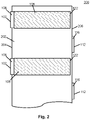
- Fig. 2 is a diagram illustrating electrodes disposed on a separator film 202 according to some embodiments.
- a continuous separator film 202 is provided to electrically insulate the cathode 102 from the anode 112 and provide ion exchange in the cell.
- the separator film 202 maybe formed from a polymer such a polyolefin, polyethylene, polypropylene, or another suitable material.
- the electrodes 100 may be disposed on the separator film 202.
- a plurality of cathodes 102 may be disposed on one side of the separator film 202, and a plurality of anodes 112 maybe disposed on an opposite side of the separator film 202.
- the cathodes 102 and anodes 112 maybe spaced apart from each other so that the electrodes align to stack without touching each other.
- each electrode 100 extends beyond an edge 204, 206 of the of separator film 202.
- the cathode contact portion 106 of each cathode 102 extends past, or across, a first edge 204 of the separator film 202, with the cathode material 108 being disposed between the first edge 204 and a second edge 206 of the separator film 202 opposite the first edge 204.
- the anodes 112 maybe disposed on an opposite side of the separator film 202 and the anode contact portion 116 of each anode 112 extends past or across the second edge 206 of the separator film 202, with the anode material 118 being disposed between the first edge 204 and a second edge 206.
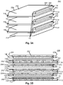
- Figs. 3A-3B are diagrams illustrating a stacked electrode structure 300 according to some embodiments.
- Fig. 3A illustrates a three dimensional view of the stacked electrode structure 300 according to some embodiments.
- Fig. 3B is a cutaway view illustrating the stacked electrode structure 330 according to some embodiments.
- the stacked electrode structure 300 is formed in an "accordion" arrangement, with the separator film 202 folded over itself to create multiple layers, each having an electrode separated by a portion of the separator film 202. Layers of the separator film 202 may be bounded by layer ends 302, 304 where the separator film 202 starts or stops a layer or section.
- Each cathode 102 and anode 112 may be disposed between a first layer end 302 and a second layer end 304, with one electrode per layer.
- Fig. 3B further illustrates that the cathodes 102 and anodes 112 are stacked in an alternating arrangement, so each cathode 102 is adjacent to an anode 112, but separated by the separator film 202. Similarly, each anode 112 is adjacent to a cathode 102, and separated by the separator film 202.
- cathode contact portions 106 extend past the first edge 204 of the separator film 202, while the anode contact portions 116 extend past the second edge 206 of the separator film 202, with the second edge 206 being opposite the separator film 202 from the first edge 204.
- separator film 202 may be discontinuous, with separate pieces of separator film 202 between the electrodes 100 to form the stacked electrode structure.
- the separator film 202 may be rolled into a spiral, rather than an accordion arrangement.
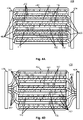
- Figs. 4A-4B are diagrams illustrating an electrode stack attached to bus bars 404 according to some embodiments.
- Fig. 4A illustrates a battery structure 400 having electrode contact portions 406 individually bonded to bus bars 404 according to some embodiments.
- An electrode stack with alternating cathodes 102 and anodes 112 separated by layers of separator film 202 may be provided, and a casing 402, a such as an insulating material, polymer, shrink wrap, or the like, maybe provided to protect and insulate the electrode stack.
- An electrolyte (not shown) may be provided to facilitate ion exchange between the cathodes 102 and anodes 1121 through the separator film 202.
- the casing 402 may be provided to enclose the electrolyte.
- the electrolyte may be a gel or liquid material such as a polymer gel comprising lithium ion complexes such as ethylene carbonate, diethyl carbonate or the like and a non-coordinating anion salts such as lithium hexafluorophosphate (LiPF6), lithium hexafluoroarsenate monohydrate (LiAsF 6 ), lithium perchlorate (LiClO 4 ), lithium tetrafluoroborate (LiBF 4 ), and lithium triflate (LiCF 3 SO 3 ) or the like.
- the electrolyte may be a solid electrolyte, or an aqueous electrolyte.
- the electrode contact portions 406 on each end of a battery may be joined to a common bus bar 404.
- the electrode contact portions 406 for each cathode 102 may be disposed at one end of the electrode stack, and may each extend past a same edge of the separator film 202 to a bus bar 404.
- the electrode contact portions 406 or each anode maybe disposed at another end of the electrode stack and my each extend past a same edge of the separator film 202 to another bus bar 404. In the embodiments illustrated in Fig.
- each electrode contact portion 406 is separately attached to a bus bar 404, and may be attached by crimping, spot welding, soldering, ultrasonic welding, using a connector such as a rivet, bolt, screw, adhesive, or the like.
- the electrode contact portion 406 may be bent and the bent portion may be attached to the bus bar 404.
- the bus bar 404 may, in some embodiments, be a conductive material having beneficial thermal transfer properties to draw heat from each cathode 102 or anode 112.
- Fig. 4B illustrates a battery structure 430 having electrode contact portions 406 bonded as a group to bus bars 404 according to some embodiments.
- the electrode contact portions 432 may be bonded to each other, and then bonded to, or placed in contact with, a bus bar 404.
- the electrode contact portions 432 may be attached to each other by crimping, spot welding, soldering, ultrasonic welding, using a connector such as a rivet, bolt, screw, adhesive, or the like, and then may be attached to the bus bar 404 using a similar or different process for providing thermal and electrical conductivity between the electrode contact portions 432 and the bus bar.
- the electrode contact portions 406, 432 in Figs 4A and 4B are shown to be relatively large in comparison to the rest of the battery structure 400, 430, the electrode contact portions 406, 432 maybe sized according to the requirements for connecting the electrode contact portions 406, 432 to each other or to the bus bars 404. After bonding or electrical connection to each other or to a bus bar 404, the contact portions 406, 432 act as a positive terminal or a negative terminal. In some embodiments, the electrode contact portions 406, 432 may extend past the edges of the separator film 202 by a distance of about imm, and in other embodiments, different lengths maybe used. Additionally, each electrode contact portion 406, 432 may have a different length. For example, with reference to Fig.
- Electrodes 102 or anodes 112 that are placed farther from the connection location may be longer than electrode contact portions 432 closer to the connection location.
- the electrode contact portions 432 after being bonded to each other, form a uniform face for contact with a bus bar 404.
- the electrode contact portions 432 may be bonded to each other, and then a surface of the bonded electrode portion group may be finished, modified, cut, milled, or otherwise shaped to achieve the desired final shape for the ends of the electrode contact portions 432, which may then be connected to a bus bar 404.
- Fig. 5 is a diagram illustrating a battery pack 500 according to some embodiments.
- One or more cells 506, formed as discussed above, may be disposed in a battery pack 500 formed from one or more rows 508A...508N or groups 510A...510N of cells.
- the arrangement shown in Fig. 5 illustrates a 3-series/4-parallel (3P4P) arrangement of cells 506.
- Each cell in a row 508A...508N maybe in series with the other cells 506 in the row.
- each cell in row 508A...508N maybe in parallel with corresponding cells 506 in another row 506A...508N to form the groups 510A...510N.
- a positive bus 502 and negative bus 504 may provide connectivity to other circuits outside of the battery pack 500.
- One or more conductive plates 512 may be provided to connect groups of cells, and act as an inter-cell bus bar to connect cells that are in series.
- the conductive plates and busses 502 provide electrical connections between cells 516 and provide support and organization for the cells 516. Additionally the conductive plate 512 and busses 502, 504 maybe used to space the cells 516 apart to provide airflow paths 514 between cells to improve cooling.
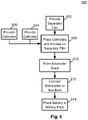
- Fig. 6 is a flow diagram illustrating a method 600 of forming a battery and battery pack according to some embodiments.
- a separator film is provided in block 602 .
- a plurality of cathodes is provided in block 604.
- Each cathode has a cathode base and a cathode material disposed on the cathode base.
- a first end of the cathode base has a cathode connection portion that is free of the cathode material.
- the cathode material extends contiguously across a width of the cathode base of the respective cathode, and extends contiguously from a second end of the cathode base to the cathode connection portion.
- the cathode connection portion of the cathode extends contiguously across the width of the cathode base.
- the cathode material comprises lithium cobalt oxide (LiCoO 2 ).
- each anode has an anode base and an anode material disposed on the anode base.
- a first end of the anode base has an anode connection portion that is free of the anode material.
- the anode material of the respective anode extends contiguously across a width of the anode base of the respective anode, and extends contiguously from a second end of the anode base to the anode connection portion of the respective anode. Additionally, the anode connection portion of the anode extends contiguously across the width of the anode base.
- the anode material comprises graphite.
- the cathodes are disposed on a first side of the separator film, and the anodes are disposed on a second side of the separator film.
- the cathode connection portion of each cathode extends from between a first edge of the separator film and a second edge of the separator film to past, or outside, the first edge of the separator film.
- the anode connection portion of each anode extends from between the first edge of the separator film and the second edge of the separator film to past, or outside, the second edge of the separator film.
- the cathode connection portion of each cathode extends past the first edge by about 1 mm
- the anode connection portion of each anode extends past the second edge by about 1 mm.
- an electrode stack is formed from the separator film, the cathodes and the anodes.
- the electrode stack has alternating anodes and cathodes, and each cathode is separated in the electrode stack from each other cathode, and is also separated from each anode of the plurality of anodes by a portion of the separator film.
- the separator film is formed into an accordion arrangement, and a single cathode or anode maybe disposed in each section of the accordion arrangement.
- the electrode connection portions are electrically connected to bus bars.
- the cathode connection portions of the cathodes are electrically connected to a first bus bar at the first end of the battery, and the anode connection portions of the anodes are electrically connected to a second bus bar at a second end of the battery.
- electrically connecting the cathode connection portions to the first bus bar comprises bonding the cathode connection portions to each other, and then connecting the bonded cathode connection portions to the first bus bar, and electrically connecting the anode connection portions the second bus bar comprises bonding the anode connection portions to each other, and then connecting the bonded anode connection portions to the second bus bar.
- each of the cathode connection portions may be bent and the individually bond to the bus bar disposed at the first end of the battery, and each of the anode connection portions may be bent and then individually bonded to the bus bar disposed at the second end of the battery.
- the battery is provided in a battery pack.
- battery is provided as part of a first group of cells that are electrically connected to each other in parallel and that are electrically connected to each other by the first bus and the second bus.
- the group of cells battery may provided in series with a second group of cells having second cells electrically connected to each other in parallel, with the first group of cells and the second group of cells all connected to one of the first bus bar or the second bus bar.
- the first bus bar and second bus bar may retain the cells of the first group of cells with airflow paths between adjacent cells of the first group of cells.
- an embodiment battery includes a separator film, a plurality of cathodes, each cathode of the plurality of cathodes having a cathode base and a cathode material disposed on the cathode base, where a first end of the cathode base of the respective cathode has a cathode connection portion that is free of the cathode material, where the cathode material of the respective cathode extends contiguously across a width of the cathode base of the respective cathode, and further extends contiguously from a second end of the cathode base of the respective cathode opposite the first end to the cathode connection portion of the respective cathode, and where the cathode connection portion of the respective cathode extends contiguously across the width of the cathode base of the respective cathode, a plurality of anodes, each anode of the plurality of anodes having
- the cathode connection portion of each cathode of the plurality of cathodes extends from between a first edge of the separator film and a second edge of the separator film opposite the first edge to past the first edge of the separator film, and the anode connection portion of each anode of the plurality of cathodes extends from between the first edge of the separator film and the second edge of the separator film to past the second edge of the separator film. In some embodiments, the cathode connection portion of each cathode of the plurality of cathodes extends past the first edge by about 1 mm, and the anode connection portion of each anode of the plurality of anodes extends past the second edge by about 1 mm.
- the separator film is formed in an accordion arrangement.
- the anode material includes graphite
- the cathode material includes lithium cobalt oxide (LiCoO 2 ).
- the cathode connection portions of the cathodes of the plurality of cathodes are connected to each other, and end surfaces of the cathode connection portions are connected to the bus bar disposed at the first end of the battery, and the anode connection portions of the anodes of the plurality of anodes are connected to each other, and end surfaces of the anode connection portions are connected to the bus bar disposed at the second end of the battery.
- the cathode connection portion of each cathode of the plurality of cathodes is individually connected to the bus bar disposed at the first end of the battery, and the anode connection portion of each anode of the plurality of anodes is individually connected to the bus bar disposed at the second end of the battery.
- An embodiment battery pack includes a plurality of bus bars, and a plurality of cells.
- Each cell includes a separator film, and an electrode stack including a plurality of electrodes, each electrode of the plurality of electrodes having an electrode base and an electrode material disposed on the electrode base, where a first end of the electrode base of the respective electrode has an electrode connection portion that is free of the electrode material, where the electrode material of the respective electrode extends contiguously across a width of the electrode base of the respective electrode, and further extends contiguously from a second end of the electrode base of the respective electrode opposite the first end to the electrode connection portion of the respective electrode, and where the electrode connection portion of the respective cathode extends contiguously across the width of the electrode base of the respective electrode, where adjacent electrodes of the plurality of electrodes are separated from each other by a portion of the separator film, and where first electrode connection portions of a first group of electrodes of the plurality of electrodes extend from between a first edge of the separator film and a second edge of the
- the electrode connection portion of each electrode of the plurality of electrodes of each cell in the plurality of cells extends past a respective edge of the separator film edge by about 1 mm.
- the separator film of each cell of the plurality of cells is formed in an accordion arrangement.
- the electrode connection portions of the electrodes of the first group of electrodes in each cell are crimped together to form the first terminal of the respective cell and are connected to a first bus bar of the plurality of bars
- the electrode connection portions of the electrodes of the second group of electrodes in each cell are crimped together to form the second terminal of the respective cell and are connected to a second bus bar of the plurality of bars.
- the plurality of bus bars retain the cells of the plurality of cells in a series-parallel configuration.
- each bus bar of the plurality of bus bars retains cells connected to the respective bus bar with an airflow path between adjacent cells.
- An embodiment method for providing a battery includes providing a separator film, providing a plurality of cathodes, each cathode of the plurality of cathodes having a cathode base and a cathode material disposed on the cathode base, where a first end of the cathode base of the respective cathode has a cathode connection portion that is free of the cathode material, where the cathode material of the respective cathode extends contiguously across a width of the cathode base of the respective cathode, and further extends contiguously from a second end of the cathode base of the respective cathode opposite the first end to the cathode connection portion of the respective cathode, and where the cathode connection portion of the respective cathode extends contiguously across the width of the cathode base of the respective cathode, providing a plurality of anodes, each anode of the plurality of anodes
- the cathode connection portion of each cathode of the plurality of cathodes extends past the first edge by about 1 mm, and the anode connection portion of each anode of the plurality of anodes extends past the second edge by about 1 mm.
- the forming an electrode stack includes forming the separator film is formed into an accordion arrangement.
- the anode material includes graphite, and the cathode material includes lithium cobalt oxide (LiCoO 2 ).
- the electrically connecting the cathode connection portions of the cathodes to the first bus bar includes bonding the cathode connection portions of the cathodes of the plurality of cathodes to each other, and connecting the bonded cathode connection portions to the first bus bar
- the electrically connecting the anode connection portions of the anodes to the second bus bar includes bonding the anode connection portions of the anodes of the plurality of anodes to each other, and connecting the bonded anode connection portions to the second bus bar.
- the electrically connecting the cathode connection portions to the bus bar includes bending each of the cathode connection portions and individually bonding each of the cathode connection portions to the bus bar disposed at the first end of the battery, and the electrically connecting the anode connection portions to the bus bar includes bending each of the anode connection portions and individually bonding each of the anode connection portions to the bus bar disposed at the second end of the battery.
- the method further includes providing the battery in a battery pack and as part of a first group of cells that are electrically connected to each other in parallel and that are electrically connected to each other by the first bus and the second bus, and providing the first group of cells in series with a second group of cells having second cells electrically connected to each other in parallel, and wherein the first group of cells and the second group of cells are all connected to one of the first bus bar or the second bus bar.
- the first bus bar and second bus bar retain the cells of the first group of cells with airflow paths between adjacent cells of the first group of cells.
Landscapes
- Chemical & Material Sciences (AREA)
- Chemical Kinetics & Catalysis (AREA)
- Electrochemistry (AREA)
- General Chemical & Material Sciences (AREA)
- Engineering & Computer Science (AREA)
- Manufacturing & Machinery (AREA)
- Inorganic Chemistry (AREA)
- Materials Engineering (AREA)
- Connection Of Batteries Or Terminals (AREA)
Abstract
A battery including a separator film (202), a plurality of cathodes (102), each having a cathode base (104), a first end of each cathode base (104) having a cathode connection portion (106) extending contiguously across the width of the cathode base (104) and free of a cathode material (108), the battery including a plurality of anodes (112), each having an anode base (114), a first end of each anode base (114) having an anode connection portion (116) extending contiguously across the width of the anode base (114) and free of an anode material (118), and the anode connection portion. The cathodes (102) and anodes (112) are in an electrode stack with alternating anodes (112) and cathodes (102) and each separated by a portion of the separator film (202). Each cathode connection portion (106) of each cathode (102) connected to a bus bar (404) at a first end of the battery, and each anode connection portion (116) electrically connected to a bus bar (404) disposed at a second end of the battery.
Description
- The present invention relates generally to a system and method for providing a thermally efficient pouch cell battery, and, in particular embodiments, to a system and method for providing a pouch cell battery with full width electrodes that are disposed at opposite ends of the pouch cell battery to provide improved current and heat distribution.
- As more devices and vehicles move to electric power, the need for increased energy storage to power those device and vehicles has grown. In particular, research into creating more power dense storage has resulted in high power battery cells capable of increasingly dense power storage, as well as high current drain, particularly for electric vehicles. However, with high power densities and high charge or discharge rates, management of heat produced by the high current charging and discharging increasingly becomes an engineering challenge.
- Many modern batteries take on two different forms, namely cylindrical cells and pouch cells. Cylindrical batteries use two continuous electrodes rolled in a spiral, while pouch cell batteries tend to use multiple electrodes in a stack configuration. However, while the pouch cell arrangement provides for greater energy density within given space, the arrangement of the stacked electrodes, particularly for high current drain application, can lead to localized heat buildup in the battery, reducing performance, storage capacity and battery lifetime.
- An embodiment battery includes a separator film, a plurality of cathodes, each cathode of the plurality of cathodes having a cathode base and a cathode material disposed on the cathode base, where a first end of the cathode base of the respective cathode has a cathode connection portion that is free of the cathode material, where the cathode material of the respective cathode extends contiguously across a width of the cathode base of the respective cathode, and further extends contiguously from a second end of the cathode base of the respective cathode opposite the first end to the cathode connection portion of the respective cathode, and where the cathode connection portion of the respective cathode extends contiguously across the width of the cathode base of the respective cathode, a plurality of anodes, each anode of the plurality of anodes having an anode base and an anode material disposed on the anode base, where a first end of the anode base of the respective anode has an anode connection portion that is free of the anode material, where the anode material of the respective anode extends contiguously across a width of the anode base of the respective anode, and further extends contiguously from a second end of the anode base of the respective anode opposite the first end to the anode connection portion of the respective anode, and where the anode connection portion of the respective anode extends contiguously across the width of the anode base of the respective anode, where the cathodes of the plurality of cathodes and the anodes of the plurality of anodes are disposed in an electrode stack with alternating anodes and cathodes, where each cathode of the plurality of cathodes is separated from each other cathode of the plurality of cathodes, and from each anode of the plurality of anodes by a portion of the separator film, and where the cathode connection portion of each cathode of the plurality of cathodes is electrically connected to a bus bar disposed at a first end of the battery, and where the anode connection portion of each anode of the plurality of anodes is electrically connected to a bus bar disposed at a second end of the battery opposite the first end.
- An embodiment battery pack includes a plurality of bus bars, and a plurality of cells. Each cell includes a separator film, and an electrode stack including a plurality of electrodes, each electrode of the plurality of electrodes having an electrode base and an electrode material disposed on the electrode base, where a first end of the electrode base of the respective electrode has an electrode connection portion that is free of the electrode material, where the electrode material of the respective electrode extends contiguously across a width of the electrode base of the respective electrode, and further extends contiguously from a second end of the electrode base of the respective electrode opposite the first end to the electrode connection portion of the respective electrode, and where the electrode connection portion of the respective cathode extends contiguously across the width of the electrode base of the respective electrode, where adjacent electrodes of the plurality of electrodes are separated from each other by a portion of the separator film, and where first electrode connection portions of a first group of electrodes of the plurality of electrodes extend from between a first edge of the separator film and a second edge of the separator film opposite the first edge to past the first edge of the separator film and are electrically connected to form a first terminal, where second electrode connection portions of a second group of electrodes of the plurality of electrodes extend from between the first edge of the separator film and the second edge of the separator film to past the second edge of the separator film, and are electrically connected to form a second terminal, where each bus bar of the plurality of bus bars connects cells of a first group of cells of the plurality of cells in parallel by connecting the first terminals or the second terminals of the cells of the first group of cells to each other, and where at least one of the bus bars connects a second group of cells of the plurality of cells in series with a third group of cells by connecting the first terminals of the cells of the first group of cells to the second terminals of the cells of the second group of cells.
- An embodiment method for providing a battery includes providing a separator film, providing a plurality of cathodes, each cathode of the plurality of cathodes having a cathode base and a cathode material disposed on the cathode base, where a first end of the cathode base of the respective cathode has a cathode connection portion that is free of the cathode material, where the cathode material of the respective cathode extends contiguously across a width of the cathode base of the respective cathode, and further extends contiguously from a second end of the cathode base of the respective cathode opposite the first end to the cathode connection portion of the respective cathode, and where the cathode connection portion of the respective cathode extends contiguously across the width of the cathode base of the respective cathode, providing a plurality of anodes, each anode of the plurality of anodes having an anode base and an anode material disposed on the anode base, where a first end of the anode base of the respective anode has an anode connection portion that is free of the anode material, where the anode material of the respective anode extends contiguously across a width of the anode base of the respective anode, and further extends contiguously from a second end of the anode base of the respective anode opposite the first end to the anode connection portion of the respective anode, and where the anode connection portion of the respective anode extends contiguously across the width of the anode base of the respective anode, disposing the plurality of cathodes on a first side of the separator film, where the cathode connection portion of each cathode of the plurality of cathodes extends from between a first edge of the separator film and a second edge of the separator film opposite the first edge to past the first edge of the separator film, disposing the plurality of anodes on a second side of the separator film, where the anode connection portion of each anode of the plurality of cathodes extends from between the first edge of the separator film and the second edge of the separator film to past the second edge of the separator film, forming an electrode stack from the separator film, the plurality of cathodes and the plurality of anodes, where the electrode stack has alternating anodes and cathodes, and where each cathode of the plurality of cathodes is separated in the electrode stack from each other cathode of the plurality of cathodes, and from each anode of the plurality of anodes by a portion of the separator film, and electrically connecting the cathode connection portions of the cathodes of the plurality of cathodes to a first bus bar disposed at a first end of the battery. and electrically connecting anode connection portions of the anodes of the plurality of anodes to a second bus bar disposed at a second end of the battery opposite the first end.
- For a more complete understanding of the present invention, and the advantages thereof, reference is now made to the following descriptions taken in conjunction with the accompanying drawings, in which:
-
Fig. 1A is a diagram illustrating electrodes according to some embodiments; -
Fig. 1B is a diagram illustrating current flow in the electrodes according to some embodiments; -
Fig. 2 is a diagram illustrating electrodes disposed on a separator film according to some embodiments; -
Figs. 3A-3B are diagrams illustrating a stacked electrode structure according to some embodiments; -
Figs. 4A-4B are diagrams illustrating an electrode stack attached to bus bars according to some embodiments; -
Fig. 5 is a diagram illustrating a battery pack according to some embodiments; and -
Fig. 6 is a flow diagram illustrating a method of forming a battery and battery pack according to some embodiments. - Illustrative embodiments of the system and method of the present disclosure are described below. In the interest of clarity, all features of an actual implementation may not be described in this specification. It will of course be appreciated that in the development of any such actual embodiment, numerous implementation-specific decisions may be made to achieve the developer's specific goals, such as compliance with system-related and business-related constraints, which will vary from one implementation to another. Moreover, it should be appreciated that such a development effort might be complex and time-consuming but would nevertheless be a routine undertaking for those of ordinary skill in the art having the benefit of this disclosure.
- Reference may be made herein to the spatial relationships between various components and to the spatial orientation of various aspects of components as the devices are depicted in the attached drawings. However, as will be recognized by those skilled in the art after a complete reading of the present disclosure, the devices, members, apparatuses, etc. described herein may be positioned in any desired orientation. Thus, the use of terms such as "above," "below," "upper," "lower," or other like terms to describe a spatial relationship between various components or to describe the spatial orientation of aspects of such components should be understood to describe a relative relationship between the components or a spatial orientation of aspects of such components, respectively, as the device described herein may be oriented in any desired direction.
-
Fig. 1A is adiagram illustrating electrodes 100 according to some embodiments. Theelectrodes 100 for a battery may include acathode 102 andanode 112. Thecathode 102 may have acathode base 104, and theanode 112 may have ananode base 114 that are each formed from a conductive material such as copper, aluminum, gold, a metallic alloy, or another conductive material. In some embodiments, thecathode base 104 may be formed from a different material than theanode base 114. For example, thecathode base 104 may be copper, while theanode base 114 may be aluminum. Thecathode base 104 andanode base 114 act as current collectors for the electrodes, allowing movement of current or electrons out of the battery, and providing support forelectrode materials cathode material 108 is disposed on thecathode base 104, and ananode material 118 is disposed on theanode base 114. Thecathode material 108 andanode material 118 may be coatings or layers formed on a portion of therespective cathode base 104 andanode base 114. Theelectrode materials electrode material respective electrode base electrode base cathode material 108 is lithium cobalt oxide (LiCoO2), and theanode material 118 is graphite. However,other cathode materials 108 may be used, such as lithium iron phosphate (LiFePO), lithium manganese oxide (LiMn2O4), lithium nickel oxide (LiNiO2), or the like. Similarly, theanode material 108 may be a material such as sodium, lithium, silicon, or silicon oxide aluminum, tin, or the like. In other embodiments, the battery may use chemistry such as a zinc-air, nickel-cadmium (NiCd), nickel-metal hydride (NiMH), lithium iron phosphate (LiFePO4), lithium-ion polymer (Li-ion polymer/LiPo), or the like, withappropriate electrode materials - The
cathode material 108 andanode material 118 may be formed on only a portion of thecathode base 104 andanode base 114, so that thecathode 102 andanode 112 have acathode contact portion 106 andanode contact portion 116, respectively, withoutelectrode material cathode contact portion 106 andanode contact portion 116 maybe exposed electrode base material or a bare anode or bare cathode that is free of electrode material so that theelectrodes 100 may be efficiently electrically connected to other conductive elements. Thecathode contact portion 106 may disposed at afirst end 120 of thecathode base 104, and thecathode material 108 may be disposed at asecond end 122 of thecathode base 104, with thecathode material 108 extending from thesecond end 122 to thecathode contact portion 106. Similarly, theanode contact portion 116 may disposed at afirst end 130 of theanode base 114, and theanode material 118 may be disposed at asecond end 132 of theanode base 114, with theanode material 118 extending from thesecond end 132 to theanode contact portion 116. - In some embodiments, the
contact portions respective electrode 100, which provide for more linear current flow along length of theelectrodes 100, and more uniform heat generation in eachelectrode 100. -
Fig. 1B is a diagram illustratingcurrent flow 140 in theelectrodes 100 according to some embodiments. Thecurrent flow 140 in thecathode 102 is from thesecond end 122 and from thecathode material 108 to thefirst end 120 and thecathode contact portion 106. Thecurrent flow 140 in theanode 112 is from thefirst end 130 and from theanode contact portion 116 to thesecond end 132 and into theanode material 118. However, the current density in thecathode 102 andanode 112 is densest nearest thecontact portions contact portions contact portions electrode 100 allows the current being drawn from, or moved into, theelectrode material electrode 100, rather than concentrated at one corner of an electrode, as when the contact region is a small tab at the end of the electrode. This avoids non-uniform heat buildup associated with of non-uniform current pathways for contact portions that extend only partway across the width of the electrode. - The
electrodes 100 may also be arranged in the battery so that thecathode contact portion 106 is at the opposite end of the battery from theanode contact portion 116. This arrangement of thecontact portions contact portions cathode contact portion 106 inadvertently contacting theanode contact portion 116. This also results in overall cooler operation and more uniform heat distribution, as heat for the different electrode types is concentrated at opposite ends of the battery. Separating thecontact portions electrodes 100 at opposite ends of the batteries also permits the use of simple heat sinks, fins, or a common electric contact plate to pull heat away from the battery. Theseparate contact portions -
Fig. 2 is a diagram illustrating electrodes disposed on aseparator film 202 according to some embodiments. In some embodiments, acontinuous separator film 202 is provided to electrically insulate thecathode 102 from theanode 112 and provide ion exchange in the cell. Theseparator film 202 maybe formed from a polymer such a polyolefin, polyethylene, polypropylene, or another suitable material. In constructing a battery, theelectrodes 100 may be disposed on theseparator film 202. In some embodiments, a plurality ofcathodes 102 may be disposed on one side of theseparator film 202, and a plurality ofanodes 112 maybe disposed on an opposite side of theseparator film 202. Thecathodes 102 andanodes 112 maybe spaced apart from each other so that the electrodes align to stack without touching each other. - In some embodiments, each
electrode 100 extends beyond anedge separator film 202. In some embodiments, thecathode contact portion 106 of eachcathode 102 extends past, or across, afirst edge 204 of theseparator film 202, with thecathode material 108 being disposed between thefirst edge 204 and asecond edge 206 of theseparator film 202 opposite thefirst edge 204. Similarly, theanodes 112 maybe disposed on an opposite side of theseparator film 202 and theanode contact portion 116 of eachanode 112 extends past or across thesecond edge 206 of theseparator film 202, with theanode material 118 being disposed between thefirst edge 204 and asecond edge 206. -
Figs. 3A-3B are diagrams illustrating astacked electrode structure 300 according to some embodiments.Fig. 3A illustrates a three dimensional view of the stackedelectrode structure 300 according to some embodiments.Fig. 3B is a cutaway view illustrating the stackedelectrode structure 330 according to some embodiments. In some embodiments, the stackedelectrode structure 300 is formed in an "accordion" arrangement, with theseparator film 202 folded over itself to create multiple layers, each having an electrode separated by a portion of theseparator film 202. Layers of theseparator film 202 may be bounded by layer ends 302, 304 where theseparator film 202 starts or stops a layer or section. Eachcathode 102 andanode 112 may be disposed between afirst layer end 302 and asecond layer end 304, with one electrode per layer.Fig. 3B further illustrates that thecathodes 102 andanodes 112 are stacked in an alternating arrangement, so eachcathode 102 is adjacent to ananode 112, but separated by theseparator film 202. Similarly, eachanode 112 is adjacent to acathode 102, and separated by theseparator film 202. Additionally, thecathode contact portions 106 extend past thefirst edge 204 of theseparator film 202, while theanode contact portions 116 extend past thesecond edge 206 of theseparator film 202, with thesecond edge 206 being opposite theseparator film 202 from thefirst edge 204. - While the embodiments described herein are described in terms of an accordion arrangement,
other separator film 202 arrangements maybe used according to the presented principles. For example, in some embodiments, theseparator film 202 may be discontinuous, with separate pieces ofseparator film 202 between theelectrodes 100 to form the stacked electrode structure. In other embodiments, theseparator film 202 may be rolled into a spiral, rather than an accordion arrangement. -
Figs. 4A-4B are diagrams illustrating an electrode stack attached tobus bars 404 according to some embodiments.Fig. 4A illustrates abattery structure 400 havingelectrode contact portions 406 individually bonded tobus bars 404 according to some embodiments. An electrode stack with alternatingcathodes 102 andanodes 112 separated by layers ofseparator film 202 may be provided, and acasing 402, a such as an insulating material, polymer, shrink wrap, or the like, maybe provided to protect and insulate the electrode stack. An electrolyte (not shown) may be provided to facilitate ion exchange between thecathodes 102 and anodes 1121 through theseparator film 202. Thecasing 402 may be provided to enclose the electrolyte. In some embodiments, the electrolyte may be a gel or liquid material such as a polymer gel comprising lithium ion complexes such as ethylene carbonate, diethyl carbonate or the like and a non-coordinating anion salts such as lithium hexafluorophosphate (LiPF6), lithium hexafluoroarsenate monohydrate (LiAsF6), lithium perchlorate (LiClO4), lithium tetrafluoroborate (LiBF4), and lithium triflate (LiCF3SO3) or the like. In other embodiments, the electrolyte may be a solid electrolyte, or an aqueous electrolyte. - In some embodiments, the
electrode contact portions 406 on each end of a battery may be joined to acommon bus bar 404. For example, theelectrode contact portions 406 for eachcathode 102 may be disposed at one end of the electrode stack, and may each extend past a same edge of theseparator film 202 to abus bar 404. Similarly, theelectrode contact portions 406 or each anode maybe disposed at another end of the electrode stack and my each extend past a same edge of theseparator film 202 to anotherbus bar 404. In the embodiments illustrated inFig. 4A , eachelectrode contact portion 406 is separately attached to abus bar 404, and may be attached by crimping, spot welding, soldering, ultrasonic welding, using a connector such as a rivet, bolt, screw, adhesive, or the like. In some embodiments, theelectrode contact portion 406 may be bent and the bent portion may be attached to thebus bar 404. Thebus bar 404 may, in some embodiments, be a conductive material having beneficial thermal transfer properties to draw heat from eachcathode 102 oranode 112. -
Fig. 4B illustrates abattery structure 430 havingelectrode contact portions 406 bonded as a group tobus bars 404 according to some embodiments. In some embodiments, theelectrode contact portions 432 may be bonded to each other, and then bonded to, or placed in contact with, abus bar 404. Theelectrode contact portions 432 may be attached to each other by crimping, spot welding, soldering, ultrasonic welding, using a connector such as a rivet, bolt, screw, adhesive, or the like, and then may be attached to thebus bar 404 using a similar or different process for providing thermal and electrical conductivity between theelectrode contact portions 432 and the bus bar. - While the
electrode contact portions Figs 4A and 4B are shown to be relatively large in comparison to the rest of thebattery structure electrode contact portions electrode contact portions bus bar 404, thecontact portions electrode contact portions separator film 202 by a distance of about imm, and in other embodiments, different lengths maybe used. Additionally, eachelectrode contact portion Fig. 4B , where theelectrode contact portions 432 are bent to contact otherelectrode contact portions 432 at a connection location, someelectrode contact portions 432 may need to extend farther to reach the location where theelectrode contact portions 432 are connected, and may be sized accordingly. In such an example,cathodes 102 oranodes 112 that are placed farther from the connection location may be longer thanelectrode contact portions 432 closer to the connection location. Thus, theelectrode contact portions 432, after being bonded to each other, form a uniform face for contact with abus bar 404. Alternatively, theelectrode contact portions 432 may be bonded to each other, and then a surface of the bonded electrode portion group may be finished, modified, cut, milled, or otherwise shaped to achieve the desired final shape for the ends of theelectrode contact portions 432, which may then be connected to abus bar 404. -
Fig. 5 is a diagram illustrating abattery pack 500 according to some embodiments. One ormore cells 506, formed as discussed above, may be disposed in abattery pack 500 formed from one ormore rows 508A...508N orgroups 510A...510N of cells. The arrangement shown inFig. 5 illustrates a 3-series/4-parallel (3P4P) arrangement ofcells 506. Each cell in arow 508A...508N maybe in series with theother cells 506 in the row. Additional, each cell inrow 508A...508N maybe in parallel with correspondingcells 506 in another row 506A...508N to form thegroups 510A...510N. Apositive bus 502 andnegative bus 504 may provide connectivity to other circuits outside of thebattery pack 500. One or moreconductive plates 512 may be provided to connect groups of cells, and act as an inter-cell bus bar to connect cells that are in series. The conductive plates and busses 502 provide electrical connections between cells 516 and provide support and organization for the cells 516. Additionally theconductive plate 512 and busses 502, 504 maybe used to space the cells 516 apart to provideairflow paths 514 between cells to improve cooling. -
Fig. 6 is a flow diagram illustrating amethod 600 of forming a battery and battery pack according to some embodiments. Inblock 602, a separator film is provided. In block 604, a plurality of cathodes is provided. Each cathode has a cathode base and a cathode material disposed on the cathode base. A first end of the cathode base has a cathode connection portion that is free of the cathode material. The cathode material extends contiguously across a width of the cathode base of the respective cathode, and extends contiguously from a second end of the cathode base to the cathode connection portion. Additionally, the cathode connection portion of the cathode extends contiguously across the width of the cathode base. In some embodiments, the cathode material comprises lithium cobalt oxide (LiCoO2). - In
block 606, a plurality of anodes is provided. Each anode has an anode base and an anode material disposed on the anode base. A first end of the anode base has an anode connection portion that is free of the anode material. The anode material of the respective anode extends contiguously across a width of the anode base of the respective anode, and extends contiguously from a second end of the anode base to the anode connection portion of the respective anode. Additionally, the anode connection portion of the anode extends contiguously across the width of the anode base. In some embodiments, the anode material comprises graphite. - In
block 608, the cathodes are disposed on a first side of the separator film, and the anodes are disposed on a second side of the separator film. The cathode connection portion of each cathode extends from between a first edge of the separator film and a second edge of the separator film to past, or outside, the first edge of the separator film. The anode connection portion of each anode extends from between the first edge of the separator film and the second edge of the separator film to past, or outside, the second edge of the separator film. In some embodiments, the cathode connection portion of each cathode extends past the first edge by about 1 mm, and the anode connection portion of each anode extends past the second edge by about 1 mm. - In
block 610, an electrode stack is formed from the separator film, the cathodes and the anodes. The electrode stack has alternating anodes and cathodes, and each cathode is separated in the electrode stack from each other cathode, and is also separated from each anode of the plurality of anodes by a portion of the separator film. In some embodiments, the separator film is formed into an accordion arrangement, and a single cathode or anode maybe disposed in each section of the accordion arrangement. - In
block 612, the electrode connection portions are electrically connected to bus bars. The cathode connection portions of the cathodes are electrically connected to a first bus bar at the first end of the battery, and the anode connection portions of the anodes are electrically connected to a second bus bar at a second end of the battery. In some embodiments, electrically connecting the cathode connection portions to the first bus bar comprises bonding the cathode connection portions to each other, and then connecting the bonded cathode connection portions to the first bus bar, and electrically connecting the anode connection portions the second bus bar comprises bonding the anode connection portions to each other, and then connecting the bonded anode connection portions to the second bus bar. In other embodiments, each of the cathode connection portions may be bent and the individually bond to the bus bar disposed at the first end of the battery, and each of the anode connection portions may be bent and then individually bonded to the bus bar disposed at the second end of the battery. - In
block 614, the battery is provided in a battery pack. In some embodiments, battery is provided as part of a first group of cells that are electrically connected to each other in parallel and that are electrically connected to each other by the first bus and the second bus. The group of cells battery may provided in series with a second group of cells having second cells electrically connected to each other in parallel, with the first group of cells and the second group of cells all connected to one of the first bus bar or the second bus bar. The first bus bar and second bus bar may retain the cells of the first group of cells with airflow paths between adjacent cells of the first group of cells. - In view of the foregoing, an embodiment battery includes a separator film, a plurality of cathodes, each cathode of the plurality of cathodes having a cathode base and a cathode material disposed on the cathode base, where a first end of the cathode base of the respective cathode has a cathode connection portion that is free of the cathode material, where the cathode material of the respective cathode extends contiguously across a width of the cathode base of the respective cathode, and further extends contiguously from a second end of the cathode base of the respective cathode opposite the first end to the cathode connection portion of the respective cathode, and where the cathode connection portion of the respective cathode extends contiguously across the width of the cathode base of the respective cathode, a plurality of anodes, each anode of the plurality of anodes having an anode base and an anode material disposed on the anode base, where a first end of the anode base of the respective anode has an anode connection portion that is free of the anode material, where the anode material of the respective anode extends contiguously across a width of the anode base of the respective anode, and further extends contiguously from a second end of the anode base of the respective anode opposite the first end to the anode connection portion of the respective anode, and where the anode connection portion of the respective anode extends contiguously across the width of the anode base of the respective anode, where the cathodes of the plurality of cathodes and the anodes of the plurality of anodes are disposed in an electrode stack with alternating anodes and cathodes, where each cathode of the plurality of cathodes is separated from each other cathode of the plurality of cathodes, and from each anode of the plurality of anodes by a portion of the separator film, and where the cathode connection portion of each cathode of the plurality of cathodes is electrically connected to a bus bar disposed at a first end of the battery, and where the anode connection portion of each anode of the plurality of anodes is electrically connected to a bus bar disposed at a second end of the battery opposite the first end.
- In some embodiments, the cathode connection portion of each cathode of the plurality of cathodes extends from between a first edge of the separator film and a second edge of the separator film opposite the first edge to past the first edge of the separator film, and the anode connection portion of each anode of the plurality of cathodes extends from between the first edge of the separator film and the second edge of the separator film to past the second edge of the separator film. In some embodiments, the cathode connection portion of each cathode of the plurality of cathodes extends past the first edge by about 1 mm, and the anode connection portion of each anode of the plurality of anodes extends past the second edge by about 1 mm. In some embodiments, the separator film is formed in an accordion arrangement. In some embodiments, the anode material includes graphite, and the cathode material includes lithium cobalt oxide (LiCoO2). In some embodiments, the cathode connection portions of the cathodes of the plurality of cathodes are connected to each other, and end surfaces of the cathode connection portions are connected to the bus bar disposed at the first end of the battery, and the anode connection portions of the anodes of the plurality of anodes are connected to each other, and end surfaces of the anode connection portions are connected to the bus bar disposed at the second end of the battery. In some embodiments, the cathode connection portion of each cathode of the plurality of cathodes is individually connected to the bus bar disposed at the first end of the battery, and the anode connection portion of each anode of the plurality of anodes is individually connected to the bus bar disposed at the second end of the battery.
- An embodiment battery pack includes a plurality of bus bars, and a plurality of cells. Each cell includes a separator film, and an electrode stack including a plurality of electrodes, each electrode of the plurality of electrodes having an electrode base and an electrode material disposed on the electrode base, where a first end of the electrode base of the respective electrode has an electrode connection portion that is free of the electrode material, where the electrode material of the respective electrode extends contiguously across a width of the electrode base of the respective electrode, and further extends contiguously from a second end of the electrode base of the respective electrode opposite the first end to the electrode connection portion of the respective electrode, and where the electrode connection portion of the respective cathode extends contiguously across the width of the electrode base of the respective electrode, where adjacent electrodes of the plurality of electrodes are separated from each other by a portion of the separator film, and where first electrode connection portions of a first group of electrodes of the plurality of electrodes extend from between a first edge of the separator film and a second edge of the separator film opposite the first edge to past the first edge of the separator film and are electrically connected to form a first terminal, where second electrode connection portions of a second group of electrodes of the plurality of electrodes extend from between the first edge of the separator film and the second edge of the separator film to past the second edge of the separator film, and are electrically connected to form a second terminal, where each bus bar of the plurality of bus bars connects cells of a first group of cells of the plurality of cells in parallel by connecting the first terminals or the second terminals of the cells of the first group of cells to each other, and where at least one of the bus bars connects a second group of cells of the plurality of cells in series with a third group of cells by connecting the first terminals of the cells of the first group of cells to the second terminals of the cells of the second group of cells.
- In some embodiments, the electrode connection portion of each electrode of the plurality of electrodes of each cell in the plurality of cells extends past a respective edge of the separator film edge by about 1 mm. In some embodiments, the separator film of each cell of the plurality of cells is formed in an accordion arrangement. In some embodiments, the electrode connection portions of the electrodes of the first group of electrodes in each cell are crimped together to form the first terminal of the respective cell and are connected to a first bus bar of the plurality of bars, and the electrode connection portions of the electrodes of the second group of electrodes in each cell are crimped together to form the second terminal of the respective cell and are connected to a second bus bar of the plurality of bars. In some embodiments, the plurality of bus bars retain the cells of the plurality of cells in a series-parallel configuration. In some embodiments, each bus bar of the plurality of bus bars retains cells connected to the respective bus bar with an airflow path between adjacent cells.
- An embodiment method for providing a battery includes providing a separator film, providing a plurality of cathodes, each cathode of the plurality of cathodes having a cathode base and a cathode material disposed on the cathode base, where a first end of the cathode base of the respective cathode has a cathode connection portion that is free of the cathode material, where the cathode material of the respective cathode extends contiguously across a width of the cathode base of the respective cathode, and further extends contiguously from a second end of the cathode base of the respective cathode opposite the first end to the cathode connection portion of the respective cathode, and where the cathode connection portion of the respective cathode extends contiguously across the width of the cathode base of the respective cathode, providing a plurality of anodes, each anode of the plurality of anodes having an anode base and an anode material disposed on the anode base, where a first end of the anode base of the respective anode has an anode connection portion that is free of the anode material, where the anode material of the respective anode extends contiguously across a width of the anode base of the respective anode, and further extends contiguously from a second end of the anode base of the respective anode opposite the first end to the anode connection portion of the respective anode, and where the anode connection portion of the respective anode extends contiguously across the width of the anode base of the respective anode, disposing the plurality of cathodes on a first side of the separator film, where the cathode connection portion of each cathode of the plurality of cathodes extends from between a first edge of the separator film and a second edge of the separator film opposite the first edge to past the first edge of the separator film, disposing the plurality of anodes on a second side of the separator film, where the anode connection portion of each anode of the plurality of cathodes extends from between the first edge of the separator film and the second edge of the separator film to past the second edge of the separator film, forming an electrode stack from the separator film, the plurality of cathodes and the plurality of anodes, where the electrode stack has alternating anodes and cathodes, and where each cathode of the plurality of cathodes is separated in the electrode stack from each other cathode of the plurality of cathodes, and from each anode of the plurality of anodes by a portion of the separator film, and electrically connecting the cathode connection portions of the cathodes of the plurality of cathodes to a first bus bar disposed at a first end of the battery. and electrically connecting anode connection portions of the anodes of the plurality of anodes to a second bus bar disposed at a second end of the battery opposite the first end.
- In some embodiments, the cathode connection portion of each cathode of the plurality of cathodes extends past the first edge by about 1 mm, and the anode connection portion of each anode of the plurality of anodes extends past the second edge by about 1 mm. In some embodiments, the forming an electrode stack includes forming the separator film is formed into an accordion arrangement. In some embodiments, the anode material includes graphite, and the cathode material includes lithium cobalt oxide (LiCoO2). In some embodiments, the electrically connecting the cathode connection portions of the cathodes to the first bus bar includes bonding the cathode connection portions of the cathodes of the plurality of cathodes to each other, and connecting the bonded cathode connection portions to the first bus bar, and the electrically connecting the anode connection portions of the anodes to the second bus bar includes bonding the anode connection portions of the anodes of the plurality of anodes to each other, and connecting the bonded anode connection portions to the second bus bar. In some embodiments, the electrically connecting the cathode connection portions to the bus bar includes bending each of the cathode connection portions and individually bonding each of the cathode connection portions to the bus bar disposed at the first end of the battery, and the electrically connecting the anode connection portions to the bus bar includes bending each of the anode connection portions and individually bonding each of the anode connection portions to the bus bar disposed at the second end of the battery. In some embodiments, the method further includes providing the battery in a battery pack and as part of a first group of cells that are electrically connected to each other in parallel and that are electrically connected to each other by the first bus and the second bus, and providing the first group of cells in series with a second group of cells having second cells electrically connected to each other in parallel, and wherein the first group of cells and the second group of cells are all connected to one of the first bus bar or the second bus bar. The first bus bar and second bus bar retain the cells of the first group of cells with airflow paths between adjacent cells of the first group of cells.
- While this invention has been described with reference to illustrative embodiments, this description is not intended to be construed in a limiting sense. Various modifications and combinations of the illustrative embodiments, as well as other embodiments of the invention, will be apparent to persons skilled in the art upon reference to the description. It is therefore intended that the appended claims encompass any such modifications or embodiments.
Claims (15)
- A battery, comprising:a separator film;a plurality of cathodes, each cathode of the plurality of cathodes having a cathode base and a cathode material disposed on the cathode base, wherein a first end of the cathode base of the respective cathode has a cathode connection portion that is free of the cathode material, wherein the cathode material of the respective cathode extends contiguously across a width of the cathode base of the respective cathode, and further extends contiguously from a second end of the cathode base of the respective cathode opposite the first end to the cathode connection portion of the respective cathode, and wherein the cathode connection portion of the respective cathode extends contiguously across the width of the cathode base of the respective cathode; anda plurality of anodes, each anode of the plurality of anodes having an anode base and an anode material disposed on the anode base, wherein a first end of the anode base of the respective anode has an anode connection portion that is free of the anode material, wherein the anode material of the respective anode extends contiguously across a width of the anode base of the respective anode, and further extends contiguously from a second end of the anode base of the respective anode opposite the first end to the anode connection portion of the respective anode, and wherein the anode connection portion of the respective anode extends contiguously across the width of the anode base of the respective anode;wherein the cathodes of the plurality of cathodes and the anodes of the plurality of anodes are disposed in an electrode stack with alternating anodes and cathodes;wherein each cathode of the plurality of cathodes is separated from each other cathode of the plurality of cathodes, and from each anode of the plurality of anodes by a portion of the separator film; andwherein the cathode connection portion of each cathode of the plurality of cathodes is electrically connected to a bus bar disposed at a first end of the battery, and wherein the anode connection portion of each anode of the plurality of anodes is electrically connected to a bus bar disposed at a second end of the battery opposite the first end.
- The battery of Claim 1, wherein:(i) the cathode connection portion of each cathode of the plurality of cathodes extends from between a first edge of the separator film and a second edge of the separator film opposite the first edge to past the first edge of the separator film, and wherein the anode connection portion of each anode of the plurality of cathodes extends from between the first edge of the separator film and the second edge of the separator film to past the second edge of the separator film; and optionally or preferably wherein(ii) the cathode connection portion of each cathode of the plurality of cathodes extends past the first edge by about 1 mm, and wherein the anode connection portion of each anode of the plurality of anodes extends past the second edge by about 1 mm.
- The battery of Claim 1 or Claim 2, wherein:(i) the separator film is formed in an accordion arrangement(ii) the anode material comprises graphite, and wherein the cathode material comprises lithium cobalt oxide (LiCoO2).
- The battery of Claim 1 or Claim 2 or Claim 3, wherein the cathode connection portions of the cathodes of the plurality of cathodes are connected to each other, and wherein end surfaces of the cathode connection portions are connected to the bus bar disposed at the first end of the battery, and wherein the anode connection portions of the anodes of the plurality of anodes are connected to each other, and wherein end surfaces of the anode connection portions are connected to the bus bar disposed at the second end of the battery.
- The battery of any of Claims 1 to 4 wherein the cathode connection portion of each cathode of the plurality of cathodes is individually connected to the bus bar disposed at the first end of the battery, and wherein the anode connection portion of each anode of the plurality of anodes is individually connected to the bus bar disposed at the second end of the battery.
- A battery pack, comprising:a plurality of bus bars; anda plurality of cells, each cell comprising:a separator film; andan electrode stack comprising a plurality of electrodes, each electrode of the plurality of electrodes having an electrode base and an electrode material disposed on the electrode base, wherein a first end of the electrode base of the respective electrode has an electrode connection portion that is free of the electrode material, wherein the electrode material of the respective electrode extends contiguously across a width of the electrode base of the respective electrode, and further extends contiguously from a second end of the electrode base of the respective electrode opposite the first end to the electrode connection portion of the respective electrode, and wherein the electrode connection portion of the respective cathode extends contiguously across the width of the electrode base of the respective electrode, wherein adjacent electrodes of the plurality of electrodes are separated from each other by a portion of the separator film, and wherein first electrode connection portions of a first group of electrodes of the plurality of electrodes extend from between a first edge of the separator film and a second edge of the separator film opposite the first edge to past the first edge of the separator film and are electrically connected to form a first terminal, wherein second electrode connection portions of a second group of electrodes of the plurality of electrodes extend from between the first edge of the separator film and the second edge of the separator film to past the second edge of the separator film, and are electrically connected to form a second terminal;wherein each bus bar of the plurality of bus bars connects cells of a first group of cells of the plurality of cells in parallel by connecting the first terminals or the second terminals of the cells of the first group of cells to each other, and wherein at least one of the bus bars connects a second group of cells of the plurality of cells in series with a third group of cells by connecting the first terminals of the cells of the first group of cells to the second terminals of the cells of the second group of cells.
- The battery pack of Claim 6, wherein:(i) the electrode connection portion of each electrode of the plurality of electrodes of each cell in the plurality of cells extends past a respective edge of the separator film edge by about 1 mm; and/or(ii) the separator film of each cell of the plurality of cells is formed in an accordion arrangement.
- The battery pack of Claim 6 or Claim 7, wherein the electrode connection portions of the electrodes of the first group of electrodes in each cell are crimped together to form the first terminal of the respective cell and are connected to a first bus bar of the plurality of bars; and
wherein the electrode connection portions of the electrodes of the second group of electrodes in each cell are crimped together to form the second terminal of the respective cell and are connected to a second bus bar of the plurality of bars. - The battery pack of Claim 6 or Claim 7 or Claim 8, wherein:(i) the plurality of bus bars retain the cells of the plurality of cells in a series-parallel configuration; and/or(ii) each bus bar of the plurality of bus bars retains cells connected to the respective bus bar with an airflow path between adjacent cells.
- A method for providing a battery, comprising:providing a separator film;providing a plurality of cathodes, each cathode of the plurality of cathodes having a cathode base and a cathode material disposed on the cathode base, wherein a first end of the cathode base of the respective cathode has a cathode connection portion that is free of the cathode material, wherein the cathode material of the respective cathode extends contiguously across a width of the cathode base of the respective cathode, and further extends contiguously from a second end of the cathode base of the respective cathode opposite the first end to the cathode connection portion of the respective cathode, and wherein the cathode connection portion of the respective cathode extends contiguously across the width of the cathode base of the respective cathode;providing a plurality of anodes, each anode of the plurality of anodes having an anode base and an anode material disposed on the anode base, wherein a first end of the anode base of the respective anode has an anode connection portion that is free of the anode material, wherein the anode material of the respective anode extends contiguously across a width of the anode base of the respective anode, and further extends contiguously from a second end of the anode base of the respective anode opposite the first end to the anode connection portion of the respective anode, and wherein the anode connection portion of the respective anode extends contiguously across the width of the anode base of the respective anode;disposing the plurality of cathodes on a first side of the separator film, wherein the cathode connection portion of each cathode of the plurality of cathodes extends from between a first edge of the separator film and a second edge of the separator film opposite the first edge to past the first edge of the separator film,disposing the plurality of anodes on a second side of the separator film, wherein the anode connection portion of each anode of the plurality of cathodes extends from between the first edge of the separator film and the second edge of the separator film to past the second edge of the separator film;forming an electrode stack from the separator film, the plurality of cathodes and the plurality of anodes, wherein the electrode stack has alternating anodes and cathodes, and wherein each cathode of the plurality of cathodes is separated in the electrode stack from each other cathode of the plurality of cathodes, and from each anode of the plurality of anodes by a portion of the separator film;electrically connecting the cathode connection portions of the cathodes of the plurality of cathodes to a first bus bar disposed at a first end of the battery; andelectrically connecting anode connection portions of the anodes of the plurality of anodes to a second bus bar disposed at a second end of the battery opposite the first end.
- The method of Claim 10, wherein the cathode connection portion of each cathode of the plurality of cathodes extends past the first edge by about 1 mm, and wherein the anode connection portion of each anode of the plurality of anodes extends past the second edge by about 1 mm.
- The method of Claim 10 or Claim 11, wherein:(i) the forming an electrode stack comprises forming the separator film is formed into an accordion arrangement; and/or(ii) the anode material comprises graphite, and wherein the cathode material comprises lithium cobalt oxide (LiCoO2).
- The method of any of Claims 10 to 12, wherein the electrically connecting the cathode connection portions of the cathodes to the first bus bar comprises bonding the cathode connection portions of the cathodes of the plurality of cathodes to each other, and connecting the bonded cathode connection portions to the first bus bar; and
wherein the electrically connecting the anode connection portions of the anodes to the second bus bar comprises bonding the anode connection portions of the anodes of the plurality of anodes to each other, and connecting the bonded anode connection portions to the second bus bar. - The method of any of Claims 10 to 13, wherein the electrically connecting the cathode connection portions to the bus bar comprises bending each of the cathode connection portions and individually bonding each of the cathode connection portions to the bus bar disposed at the first end of the battery; and
wherein the electrically connecting the anode connection portions to the bus bar comprises bending each of the anode connection portions and individually bonding each of the anode connection portions to the bus bar disposed at the second end of the battery. - The method of any of Claims 10 to 14, further comprising providing the battery in a battery pack and as part of a first group of cells that are electrically connected to each other in parallel and that are electrically connected to each other by the first bus and the second bus; andproviding the first group of cells in series with a second group of cells having second cells electrically connected to each other in parallel, and wherein the first group of cells and the second group of cells are all connected to one of the first bus bar or the second bus bar;wherein the first bus bar and second bus bar retain the cells of the first group of cells with airflow paths between adjacent cells of the first group of cells.
Applications Claiming Priority (1)
| Application Number | Priority Date | Filing Date | Title |
|---|---|---|---|
| US17/332,777 US20220384912A1 (en) | 2021-05-27 | 2021-05-27 | Thermally Efficient Pouch Cell Architecture |
Publications (1)
| Publication Number | Publication Date |
|---|---|
| EP4095997A1 true EP4095997A1 (en) | 2022-11-30 |
Family
ID=81327190
Family Applications (1)
| Application Number | Title | Priority Date | Filing Date |
|---|---|---|---|
| EP22166226.5A Pending EP4095997A1 (en) | 2021-05-27 | 2022-03-31 | Thermally efficient pouch cell architecture |
Country Status (2)
| Country | Link |
|---|---|
| US (1) | US20220384912A1 (en) |
| EP (1) | EP4095997A1 (en) |
Citations (4)
| Publication number | Priority date | Publication date | Assignee | Title |
|---|---|---|---|---|
| JPH06231797A (en) * | 1993-02-08 | 1994-08-19 | Tdk Corp | Layered type cell |
| EP1148569A2 (en) * | 2000-04-18 | 2001-10-24 | Matsushita Electric Industrial Co., Ltd. | Prismatic battery and method of manufacturing same |
| JP4784687B2 (en) * | 2009-10-09 | 2011-10-05 | 日本電気株式会社 | Flat battery and battery pack using the same |
| US20130224562A1 (en) * | 2012-02-29 | 2013-08-29 | Semiconductor Energy Laboratory Co., Ltd. | Power storage device |
Family Cites Families (7)
| Publication number | Priority date | Publication date | Assignee | Title |
|---|---|---|---|---|
| JP2008269972A (en) * | 2007-04-20 | 2008-11-06 | Nissan Motor Co Ltd | Non-aqueous solvent secondary battery |
| JP2012174971A (en) * | 2011-02-23 | 2012-09-10 | Jm Energy Corp | Power storage device |
| KR101669123B1 (en) * | 2014-03-03 | 2016-10-25 | 주식회사 엘지화학 | Pouch type secondary battery and battery module including the same |
| US10074870B2 (en) * | 2016-08-15 | 2018-09-11 | Microsoft Technology Licensing, Llc | Battery with perforated continuous separator |
| JP6980587B2 (en) * | 2018-03-23 | 2021-12-15 | 株式会社東芝 | Electrodes, rechargeable batteries, battery packs, and vehicles |
| KR102384970B1 (en) * | 2018-08-13 | 2022-04-11 | 주식회사 엘지에너지솔루션 | Electrode and method for electrode manufacture for the same |
| US12074321B2 (en) * | 2019-08-21 | 2024-08-27 | Apple Inc. | Cathode active materials for lithium ion batteries |
-
2021
- 2021-05-27 US US17/332,777 patent/US20220384912A1/en not_active Abandoned
-
2022
- 2022-03-31 EP EP22166226.5A patent/EP4095997A1/en active Pending
Patent Citations (4)
| Publication number | Priority date | Publication date | Assignee | Title |
|---|---|---|---|---|
| JPH06231797A (en) * | 1993-02-08 | 1994-08-19 | Tdk Corp | Layered type cell |
| EP1148569A2 (en) * | 2000-04-18 | 2001-10-24 | Matsushita Electric Industrial Co., Ltd. | Prismatic battery and method of manufacturing same |
| JP4784687B2 (en) * | 2009-10-09 | 2011-10-05 | 日本電気株式会社 | Flat battery and battery pack using the same |
| US20130224562A1 (en) * | 2012-02-29 | 2013-08-29 | Semiconductor Energy Laboratory Co., Ltd. | Power storage device |
Also Published As
| Publication number | Publication date |
|---|---|
| US20220384912A1 (en) | 2022-12-01 |
Similar Documents
| Publication | Publication Date | Title |
|---|---|---|
| US10454083B2 (en) | Battery module | |
| CN101478034B (en) | Protective circuit board, battery pack, and associated methods | |
| JP6788106B2 (en) | How to Make Electrode Stacks for Battery Cells and Battery Cells | |
| KR102618844B1 (en) | Lead tabs for battery terminals | |
| CN103119764A (en) | Battery comprising cuboid cells which contain a bipolar electrode | |
| US11552376B2 (en) | Electrode assembly and method for manufacturing the same | |
| US11394093B2 (en) | Secondary battery and battery module | |
| US20240097266A1 (en) | Battery assembly and method therefor | |
| KR101431726B1 (en) | Electrode Assembly of Improved Safety And Secondary Battery with the Same | |
| US20230268583A1 (en) | Battery | |
| EP4095997A1 (en) | Thermally efficient pouch cell architecture | |
| KR20130110400A (en) | Battery module | |
| CN108140877B (en) | Secondary battery | |
| JP7462764B2 (en) | Secondary battery and battery module | |
| KR102724246B1 (en) | Long width secondary battery | |
| EP4542696A1 (en) | Battery cell with electrode stack and method for manufacturing a battery cell | |
| US20250105473A1 (en) | Battery cell, battery module including battery cell, and battery pack including battery module | |
| US20250046788A1 (en) | Power supply device | |
| US10629915B2 (en) | Battery pack with battery cells having asymmetrical packaging and symmetrical current flow paths | |
| CN121790697A (en) | Battery devices and electrical equipment | |
| CN121769452A (en) | Batteries and battery devices | |
| KR20250100160A (en) | Battery cell assembly, secondary battery pack including same, and method of manufacturing secondary battery pack including same | |
| KR20220075045A (en) | Battery module and battery pack including the same and vehicle including the same |
Legal Events
| Date | Code | Title | Description |
|---|---|---|---|
| PUAI | Public reference made under article 153(3) epc to a published international application that has entered the european phase |
Free format text: ORIGINAL CODE: 0009012 |
|
| STAA | Information on the status of an ep patent application or granted ep patent |
Free format text: STATUS: EXAMINATION IS IN PROGRESS |
|
| 17P | Request for examination filed |
Effective date: 20220331 |
|
| AK | Designated contracting states |
Kind code of ref document: A1 Designated state(s): AL AT BE BG CH CY CZ DE DK EE ES FI FR GB GR HR HU IE IS IT LI LT LU LV MC MK MT NL NO PL PT RO RS SE SI SK SM TR |
|
| RAP3 | Party data changed (applicant data changed or rights of an application transferred) |
Owner name: BELL TEXTRON INC. |