EP4095996A1 - Battery pack - Google Patents
Battery pack Download PDFInfo
- Publication number
- EP4095996A1 EP4095996A1 EP22174949.2A EP22174949A EP4095996A1 EP 4095996 A1 EP4095996 A1 EP 4095996A1 EP 22174949 A EP22174949 A EP 22174949A EP 4095996 A1 EP4095996 A1 EP 4095996A1
- Authority
- EP
- European Patent Office
- Prior art keywords
- battery cell
- insulating cap
- battery
- battery cells
- bus bar
- Prior art date
- Legal status (The legal status is an assumption and is not a legal conclusion. Google has not performed a legal analysis and makes no representation as to the accuracy of the status listed.)
- Pending
Links
Images


Classifications
-
- H—ELECTRICITY
- H01—ELECTRIC ELEMENTS
- H01M—PROCESSES OR MEANS, e.g. BATTERIES, FOR THE DIRECT CONVERSION OF CHEMICAL ENERGY INTO ELECTRICAL ENERGY
- H01M50/00—Constructional details or processes of manufacture of the non-active parts of electrochemical cells other than fuel cells, e.g. hybrid cells
- H01M50/20—Mountings; Secondary casings or frames; Racks, modules or packs; Suspension devices; Shock absorbers; Transport or carrying devices; Holders
- H01M50/204—Racks, modules or packs for multiple batteries or multiple cells
- H01M50/207—Racks, modules or packs for multiple batteries or multiple cells characterised by their shape
- H01M50/209—Racks, modules or packs for multiple batteries or multiple cells characterised by their shape adapted for prismatic or rectangular cells
-
- H—ELECTRICITY
- H01—ELECTRIC ELEMENTS
- H01M—PROCESSES OR MEANS, e.g. BATTERIES, FOR THE DIRECT CONVERSION OF CHEMICAL ENERGY INTO ELECTRICAL ENERGY
- H01M50/00—Constructional details or processes of manufacture of the non-active parts of electrochemical cells other than fuel cells, e.g. hybrid cells
- H01M50/50—Current conducting connections for cells or batteries
- H01M50/572—Means for preventing undesired use or discharge
- H01M50/584—Means for preventing undesired use or discharge for preventing incorrect connections inside or outside the batteries
- H01M50/59—Means for preventing undesired use or discharge for preventing incorrect connections inside or outside the batteries characterised by the protection means
- H01M50/591—Covers
-
- H—ELECTRICITY
- H01—ELECTRIC ELEMENTS
- H01M—PROCESSES OR MEANS, e.g. BATTERIES, FOR THE DIRECT CONVERSION OF CHEMICAL ENERGY INTO ELECTRICAL ENERGY
- H01M50/00—Constructional details or processes of manufacture of the non-active parts of electrochemical cells other than fuel cells, e.g. hybrid cells
- H01M50/20—Mountings; Secondary casings or frames; Racks, modules or packs; Suspension devices; Shock absorbers; Transport or carrying devices; Holders
- H01M50/271—Lids or covers for the racks or secondary casings
-
- H—ELECTRICITY
- H01—ELECTRIC ELEMENTS
- H01M—PROCESSES OR MEANS, e.g. BATTERIES, FOR THE DIRECT CONVERSION OF CHEMICAL ENERGY INTO ELECTRICAL ENERGY
- H01M50/00—Constructional details or processes of manufacture of the non-active parts of electrochemical cells other than fuel cells, e.g. hybrid cells
- H01M50/10—Primary casings, jackets or wrappings of a single cell or a single battery
- H01M50/102—Primary casings, jackets or wrappings of a single cell or a single battery characterised by their shape or physical structure
- H01M50/103—Primary casings, jackets or wrappings of a single cell or a single battery characterised by their shape or physical structure prismatic or rectangular
-
- H—ELECTRICITY
- H01—ELECTRIC ELEMENTS
- H01M—PROCESSES OR MEANS, e.g. BATTERIES, FOR THE DIRECT CONVERSION OF CHEMICAL ENERGY INTO ELECTRICAL ENERGY
- H01M50/00—Constructional details or processes of manufacture of the non-active parts of electrochemical cells other than fuel cells, e.g. hybrid cells
- H01M50/10—Primary casings, jackets or wrappings of a single cell or a single battery
- H01M50/131—Primary casings, jackets or wrappings of a single cell or a single battery characterised by physical properties, e.g. gas-permeability or size
- H01M50/133—Thickness
-
- H—ELECTRICITY
- H01—ELECTRIC ELEMENTS
- H01M—PROCESSES OR MEANS, e.g. BATTERIES, FOR THE DIRECT CONVERSION OF CHEMICAL ENERGY INTO ELECTRICAL ENERGY
- H01M50/00—Constructional details or processes of manufacture of the non-active parts of electrochemical cells other than fuel cells, e.g. hybrid cells
- H01M50/10—Primary casings, jackets or wrappings of a single cell or a single battery
- H01M50/147—Lids or covers
- H01M50/148—Lids or covers characterised by their shape
- H01M50/15—Lids or covers characterised by their shape for prismatic or rectangular cells
-
- H—ELECTRICITY
- H01—ELECTRIC ELEMENTS
- H01M—PROCESSES OR MEANS, e.g. BATTERIES, FOR THE DIRECT CONVERSION OF CHEMICAL ENERGY INTO ELECTRICAL ENERGY
- H01M50/00—Constructional details or processes of manufacture of the non-active parts of electrochemical cells other than fuel cells, e.g. hybrid cells
- H01M50/20—Mountings; Secondary casings or frames; Racks, modules or packs; Suspension devices; Shock absorbers; Transport or carrying devices; Holders
- H01M50/204—Racks, modules or packs for multiple batteries or multiple cells
-
- H—ELECTRICITY
- H01—ELECTRIC ELEMENTS
- H01M—PROCESSES OR MEANS, e.g. BATTERIES, FOR THE DIRECT CONVERSION OF CHEMICAL ENERGY INTO ELECTRICAL ENERGY
- H01M50/00—Constructional details or processes of manufacture of the non-active parts of electrochemical cells other than fuel cells, e.g. hybrid cells
- H01M50/20—Mountings; Secondary casings or frames; Racks, modules or packs; Suspension devices; Shock absorbers; Transport or carrying devices; Holders
- H01M50/244—Secondary casings; Racks; Suspension devices; Carrying devices; Holders characterised by their mounting method
-
- H—ELECTRICITY
- H01—ELECTRIC ELEMENTS
- H01M—PROCESSES OR MEANS, e.g. BATTERIES, FOR THE DIRECT CONVERSION OF CHEMICAL ENERGY INTO ELECTRICAL ENERGY
- H01M50/00—Constructional details or processes of manufacture of the non-active parts of electrochemical cells other than fuel cells, e.g. hybrid cells
- H01M50/20—Mountings; Secondary casings or frames; Racks, modules or packs; Suspension devices; Shock absorbers; Transport or carrying devices; Holders
- H01M50/262—Mountings; Secondary casings or frames; Racks, modules or packs; Suspension devices; Shock absorbers; Transport or carrying devices; Holders with fastening means, e.g. locks
- H01M50/264—Mountings; Secondary casings or frames; Racks, modules or packs; Suspension devices; Shock absorbers; Transport or carrying devices; Holders with fastening means, e.g. locks for cells or batteries, e.g. straps, tie rods or peripheral frames
-
- H—ELECTRICITY
- H01—ELECTRIC ELEMENTS
- H01M—PROCESSES OR MEANS, e.g. BATTERIES, FOR THE DIRECT CONVERSION OF CHEMICAL ENERGY INTO ELECTRICAL ENERGY
- H01M50/00—Constructional details or processes of manufacture of the non-active parts of electrochemical cells other than fuel cells, e.g. hybrid cells
- H01M50/50—Current conducting connections for cells or batteries
- H01M50/502—Interconnectors for connecting terminals of adjacent batteries; Interconnectors for connecting cells outside a battery casing
- H01M50/505—Interconnectors for connecting terminals of adjacent batteries; Interconnectors for connecting cells outside a battery casing comprising a single busbar
-
- H—ELECTRICITY
- H01—ELECTRIC ELEMENTS
- H01M—PROCESSES OR MEANS, e.g. BATTERIES, FOR THE DIRECT CONVERSION OF CHEMICAL ENERGY INTO ELECTRICAL ENERGY
- H01M50/00—Constructional details or processes of manufacture of the non-active parts of electrochemical cells other than fuel cells, e.g. hybrid cells
- H01M50/50—Current conducting connections for cells or batteries
- H01M50/502—Interconnectors for connecting terminals of adjacent batteries; Interconnectors for connecting cells outside a battery casing
- H01M50/519—Interconnectors for connecting terminals of adjacent batteries; Interconnectors for connecting cells outside a battery casing comprising printed circuit boards [PCB]
-
- H—ELECTRICITY
- H01—ELECTRIC ELEMENTS
- H01M—PROCESSES OR MEANS, e.g. BATTERIES, FOR THE DIRECT CONVERSION OF CHEMICAL ENERGY INTO ELECTRICAL ENERGY
- H01M50/00—Constructional details or processes of manufacture of the non-active parts of electrochemical cells other than fuel cells, e.g. hybrid cells
- H01M50/50—Current conducting connections for cells or batteries
- H01M50/543—Terminals
- H01M50/552—Terminals characterised by their shape
- H01M50/553—Terminals adapted for prismatic, pouch or rectangular cells
-
- H—ELECTRICITY
- H01—ELECTRIC ELEMENTS
- H01M—PROCESSES OR MEANS, e.g. BATTERIES, FOR THE DIRECT CONVERSION OF CHEMICAL ENERGY INTO ELECTRICAL ENERGY
- H01M50/00—Constructional details or processes of manufacture of the non-active parts of electrochemical cells other than fuel cells, e.g. hybrid cells
- H01M50/50—Current conducting connections for cells or batteries
- H01M50/572—Means for preventing undesired use or discharge
- H01M50/584—Means for preventing undesired use or discharge for preventing incorrect connections inside or outside the batteries
- H01M50/588—Means for preventing undesired use or discharge for preventing incorrect connections inside or outside the batteries outside the batteries, e.g. incorrect connections of terminals or busbars
-
- H—ELECTRICITY
- H01—ELECTRIC ELEMENTS
- H01M—PROCESSES OR MEANS, e.g. BATTERIES, FOR THE DIRECT CONVERSION OF CHEMICAL ENERGY INTO ELECTRICAL ENERGY
- H01M50/00—Constructional details or processes of manufacture of the non-active parts of electrochemical cells other than fuel cells, e.g. hybrid cells
- H01M50/50—Current conducting connections for cells or batteries
- H01M50/572—Means for preventing undesired use or discharge
- H01M50/584—Means for preventing undesired use or discharge for preventing incorrect connections inside or outside the batteries
- H01M50/59—Means for preventing undesired use or discharge for preventing incorrect connections inside or outside the batteries characterised by the protection means
- H01M50/593—Spacers; Insulating plates
-
- H—ELECTRICITY
- H01—ELECTRIC ELEMENTS
- H01M—PROCESSES OR MEANS, e.g. BATTERIES, FOR THE DIRECT CONVERSION OF CHEMICAL ENERGY INTO ELECTRICAL ENERGY
- H01M10/00—Secondary cells; Manufacture thereof
- H01M10/60—Heating or cooling; Temperature control
- H01M10/64—Heating or cooling; Temperature control characterised by the shape of the cells
- H01M10/647—Prismatic or flat cells, e.g. pouch cells
-
- H—ELECTRICITY
- H01—ELECTRIC ELEMENTS
- H01M—PROCESSES OR MEANS, e.g. BATTERIES, FOR THE DIRECT CONVERSION OF CHEMICAL ENERGY INTO ELECTRICAL ENERGY
- H01M10/00—Secondary cells; Manufacture thereof
- H01M10/60—Heating or cooling; Temperature control
- H01M10/65—Means for temperature control structurally associated with the cells
- H01M10/658—Means for temperature control structurally associated with the cells by thermal insulation or shielding
-
- H—ELECTRICITY
- H01—ELECTRIC ELEMENTS
- H01M—PROCESSES OR MEANS, e.g. BATTERIES, FOR THE DIRECT CONVERSION OF CHEMICAL ENERGY INTO ELECTRICAL ENERGY
- H01M50/00—Constructional details or processes of manufacture of the non-active parts of electrochemical cells other than fuel cells, e.g. hybrid cells
- H01M50/50—Current conducting connections for cells or batteries
- H01M50/502—Interconnectors for connecting terminals of adjacent batteries; Interconnectors for connecting cells outside a battery casing
- H01M50/503—Interconnectors for connecting terminals of adjacent batteries; Interconnectors for connecting cells outside a battery casing characterised by the shape of the interconnectors
-
- H—ELECTRICITY
- H01—ELECTRIC ELEMENTS
- H01M—PROCESSES OR MEANS, e.g. BATTERIES, FOR THE DIRECT CONVERSION OF CHEMICAL ENERGY INTO ELECTRICAL ENERGY
- H01M50/00—Constructional details or processes of manufacture of the non-active parts of electrochemical cells other than fuel cells, e.g. hybrid cells
- H01M50/50—Current conducting connections for cells or batteries
- H01M50/569—Constructional details of current conducting connections for detecting conditions inside cells or batteries, e.g. details of voltage sensing terminals
-
- Y—GENERAL TAGGING OF NEW TECHNOLOGICAL DEVELOPMENTS; GENERAL TAGGING OF CROSS-SECTIONAL TECHNOLOGIES SPANNING OVER SEVERAL SECTIONS OF THE IPC; TECHNICAL SUBJECTS COVERED BY FORMER USPC CROSS-REFERENCE ART COLLECTIONS [XRACs] AND DIGESTS
- Y02—TECHNOLOGIES OR APPLICATIONS FOR MITIGATION OR ADAPTATION AGAINST CLIMATE CHANGE
- Y02E—REDUCTION OF GREENHOUSE GAS [GHG] EMISSIONS, RELATED TO ENERGY GENERATION, TRANSMISSION OR DISTRIBUTION
- Y02E60/00—Enabling technologies; Technologies with a potential or indirect contribution to GHG emissions mitigation
- Y02E60/10—Energy storage using batteries
Definitions
- One or more embodiments relate to a battery pack.
- secondary batteries refer to batteries that can be repeatedly charged and recharged, unlike non-rechargeable primary batteries. Secondary batteries are used as energy sources of devices such as mobile devices, electric vehicles, hybrid electric vehicles, electric bicycles, and uninterruptible power supplies. Single-cell secondary batteries or a module form of secondary batteries each including a plurality of cells connected to each other as a unit are used according to the types of devices that employ secondary batteries.
- One or more embodiments include a battery pack including a plurality of battery cells, wherein insulation between battery cells which are arranged adjacent to each other is ensured, the rigidity of each of the plurality of battery cells may be improved while the capacity thereof is easily increased, and a manufacturing operation of the battery pack may be simplified.
- One or more embodiments include a battery pack that is flexibly expandable in an arrangement direction of battery cells to meet required output and capacity of the battery pack.
- a battery pack includes:
- the insulating cap may be individually formed for each of the plurality of battery cells arranged in the first direction.
- the main surface of the battery cell may connect between the first surface and the second surface of the battery cell and include a surface having a relatively larger area
- the battery cell may further include a side surface connecting between the first surface and the second surface of the battery cell and having a relatively narrower area.
- each of the main surface and the side surface of the battery cell may be formed in an elongated shape extending long in the second direction.
- the insulating cap may include:
- the long-side portion and the short-side portion may continuously surround edges of the first surface and the second surface of the battery cell.
- the main surface and the side surface of the battery cell may respectively include a pair of main surfaces and a pair of side surfaces, wherein the pair of main surfaces and the pair of side surfaces may be arranged to face each other, respectively, and the main surface and the side surface of the battery cell may be provided by outer surfaces of hollow cases continuously connected to each other.
- each of the hollow cases may include first and second openings respectively formed at both ends of the hollow case through cutting of a hollow member continuously extruded in the second direction.
- first and second boards may be respectively coupled to the both ends of the hollow case, wherein the first and second boards may respectively seal the first and second openings of the hollow case.
- a thickness of the hollow case may be greater than a thickness of the first board and a thickness of the second board.
- first surface and the second surface of the battery cell may be provided by outer surfaces of the first board and the second board, respectively.
- the battery cell may include an electrode connected to the bus bar, and the electrode of the battery cell may include first and second electrodes respectively protruding from the first surface and the second surface of the battery cell.
- the insulating cap may include:
- the insulating cap may further include a fixing piece formed at an edge position of the insulating cap in a third direction intersecting with the first and second directions, and the electrode hole may be formed at a central position of the insulating cap in the third direction.
- the fixing piece may include a plurality of fixing pieces arranged in the first direction to correspond to the plurality of battery cells, and the binding frame may be coupled to each of the plurality of fixing pieces while extending in the first direction.
- the binding frame may extend in the first direction and include first and second portions bent with respect to each other,
- the fixing piece may be integrally formed with a body of the insulating cap through insert injection molding.
- the insulating cap may further include, together with the electrode hole, a bonding area formed at the central position of the insulating cap.
- the electrode hole and the bonding area of the insulating cap may be formed at different positions at the central position of the insulating cap.
- the fixing piece of the insulating cap may include first and second fixing pieces respectively formed at edge positions on both sides of the insulating cap in the third direction,
- the bus bar and the binding frame may be respectively arranged at positions of the electrode hole and the fixing piece of the insulating cap, and a circuit unit connected to the bus bar may be on the bus bar and the binding frame.
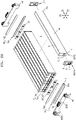
- FIG. 1 is a perspective view illustrating a battery pack according to an embodiment.
- FIGS. 2A and 2B are exploded perspective views each illustrating the battery pack shown in FIG. 1 , wherein FIGS. 2A and 2B illustrate different exploded perspective views from each other.
- FIG. 3 is an exploded perspective view illustrating the assembly of a battery cell and an insulating cap shown in FIG. 1 .
- FIG. 4 is an exploded perspective view illustrating a battery cell shown in FIG. 3 .
- FIGS. 5A and 5B are exploded perspective views each illustrating a portion of the battery pack shown in FIG. 1 , wherein FIGS. 5A and 5B illustrate different exploded perspective views from each other.
- FIGS. 6A and 6B are different perspective views each illustrating an insulating cap shown in FIG. 1 .
- the battery pack may include a plurality of battery cells C arranged in a first direction Z1, the plurality of battery cells C each including a main surface M, a first surface P1, and a second surface P2, wherein main surfaces M of battery cells C arranged adjacent to each other face each other, and the first surface P1 and the second surface P2 respectively form both ends of each of the plurality of battery cells C in a second direction Z2 intersecting with the first direction Z1, an insulating cap H arranged on the first surface P1 and the second surface P2 of the battery cell C, the insulating cap H extending from the first surface P1 and the second surface P2 to a portion of the main surface M of the battery cell C to insulate the main surfaces M of the battery cells C arranged adjacent to each other in the first direction Z1, a bus bar 30 arranged on the insulating cap H to electrically connect the plurality of battery cells to each other, and a binding frame 40 configured to structurally binding the plurality of battery
- the battery pack may include the plurality of battery cells C arranged in the first direction Z1, and may include at least two pluralities of battery cells C.
- the battery cell C may include an electrode assembly (not shown) and a case 15 accommodating the electrode assembly.
- the electrode assembly may include first and second electrode plates having different polarities from each other, and a separator between the first and second electrode plates, and may include a wound-type electrode assembly in which a laminate having the separator between the first and second electrode plates is wound in a roll shape, or a stacked-type electrode assembly in which a plurality of layers are stacked with a separator between a plurality of first and second electrode plates.
- the electrode assembly (not shown) may be electrically connected to first and second electrodes T1 and T2, which are formed on the case 15, and may output discharging power or receive charging power through the first and second electrodes T1 and T2.
- the case 15 may accommodate an electrolyte (not shown) together with the electrode assembly (not shown), and the first and second electrodes T1 and T2 each electrically connected to the electrode assembly may be formed on the case 15.
- the case 15 may include the first surface P1 and the second surface P2 on which the first and second electrodes T1 and T2 are respectively formed, the main surface M connecting between the first surface P1 and the second surface P2 and having a relatively larger area, and a side surface S connecting between the first surface P1 and the second surface P2 and having a relatively narrower area.
- the case 15 forms outer surfaces of the battery cell C, and the main surface M, the side surface S, the first surface P1, and the second surface P2 of the case 15 may correspond to the outer surfaces of the battery cell C. In this sense, the main surface M, the side surface S, the first surface P1, and the second surface P2 of the case 15 may correspond to the main surface M, the side surface S, the first surface P1, and the second surface P2 of the battery cell C, respectively.
- the first and second electrodes T1 and T2 may be formed at positions opposite to each other in the second direction Z2 intersecting with the first direction Z1.
- the second direction Z2 may correspond to a direction intersecting with the first direction Z1, and in an embodiment, the second direction Z2 may correspond to a direction that vertically intersects with the first direction Z1.
- the second direction Z2 may correspond to a longitudinal direction of the case 15, and may correspond to a longitudinal direction of the main surface M or a longitudinal direction of the side surface S, the main surface M and the side surface S forming the case 15.
- the case 15 may be formed in an elongated shape extending lengthwise in the second direction Z2, and the main surface M and the side surface S of the case 15 may also be formed in an elongated shape extending lengthwise in the second direction Z2.
- first and second electrodes T1 and T2 are respectively dispersed and arranged on the first surface P1 and the second surface P2, which are opposite to each other in the second direction Z2, in another embodiment, the first and second electrodes T1 and T2 may be closely arranged on any one of the first surface P1 and the second surface P2, and the first and second electrodes T1 and T2 may not be arranged on the other one of the first surface P1 and the second surface P2.
- electrical interference between the first and second electrodes T1 and T2 having different polarities from each other may be avoided, and an insulating structure for electrical insulation between the first and second electrodes T1 and T2 may be omitted, by distributing and arranging the first and second electrodes T1 and T2 respectively on the first surface P1 and the second surface P2, which are opposite to each other in the second direction Z2, and in this way the structure of the battery cell C may be simplified.
- first and second electrodes T1 and T2 may be formed to protrude from the first surface P1 and the second surface P2 of the battery cell C, respectively, and the first and second electrodes T1 and T2 may be formed to respectively protrude from the first surface P1 and the second surface P2 toward the outside that is opposite to the battery cell C in the second direction Z2.
- first and second electrodes T1 and T2 may be integrally formed with the first surface P1 and the second surface P2, respectively.
- the first and second electrodes T1 and T2 may be respectively formed as a portion of the first surface P2 and the second surface P2, and may be formed to respectively protrude from remaining portions of the first surface P1 and the second surface P2.
- the first and second electrodes T1 and T2 may not be formed in an insulated state from the first surface P1 and the second surface P2, respectively, and may be integrally formed with the first surface P1 and the second surface P2 as a portion of the first surface P1 and a portion of the second surface P2, respectively.
- first and second electrodes T1 and T2 are dispersedly formed on the first surface P1 and the second surface P2, which are different from each other, respectively, an insulation structure between the first and second electrodes T1 and T2 is not required, thus, an assembly of the first and second electrodes T1 and T2 respectively with respect to the first surface P1 and the second surface P2 or a complicated structure for insulation between the first and second electrodes T1 and T2 may be omitted by integrally forming the first and second electrodes T1 and T2 of the battery cell C with the first surface P1 and the second surface P2, respectively, and structures of the first surface P1 and the second surface P2 respectively including the first and second electrodes T1 and T2 may be simplified.
- the first and second electrodes T1 and T2 respectively protruding from the first surface P1 and the second surface P2 may be exposed through an electrode hole TH of the insulating cap H arranged on each of the first surface P1 and the second surface P2, and each of the first and second electrodes T1 and T2 exposed through the electrode hole TH may be electrically connected to the bus bar 30 on the insulating cap H.
- an electrical connection between the bus bar 30 and each of the first and second electrodes T1 and T2 may be formed with the insulating cap H therebetween by forming the first and second electrodes T1 and T2 to respectively protrude from the first surface P1 and the second surface P2.
- the first surface P1 and the second surface P2 may form both ends of the case 15 in the second direction Z2 corresponding to the longitudinal direction of the case 15, respectively.
- the first surface P1 and the second surface P2 may form both ends of the case 15 in the second direction Z2 corresponding to the longitudinal direction of the main surface M or the longitudinal direction of the side surface S, respectively, the main surface M and the side surface S forming the case 15.
- the insulating cap H may be arranged on the first surface P1 and the second surface P2 of the case 15, that is, the first surface P1 and the second surface P2 of the battery cell C.
- the bus bar 30 electrically connecting the plurality of battery cells C to each other, and the binding frame 40 structurally binding the plurality of battery cells C to each other may be arranged on the insulating cap H.
- the main surface M may correspond to a surface having the greatest area among surfaces forming the case 15.
- the case 15 may be formed in a substantially rectangular parallelepiped shape
- the main surface M may correspond to a surface occupying the greatest area among surfaces of the case 15 having a substantially rectangular parallelepiped shape.
- the plurality of battery cells C are arranged in the first direction Z1, more specifically, the plurality of battery cells C may be arranged such that the main surfaces M of the plurality of battery cells C face each other, the main surface M being a surface occupying the greatest area among surfaces of each of the plurality of battery cells C, so that a stable support may be formed between battery cells C, which are arranged adjacent to each other, through the main surface M occupying the greatest area.
- the main surfaces M of the battery cells C, which are arranged adjacent to each other may not directly contact each other.
- the case 15 of the battery cell C may have a polarity depending on a particular configuration of the battery cell C, and the main surfaces M of the battery cells C, which are arranged adjacent to each other, may not directly contact each other such that cases 15 each having a polarity do not electrically interfere with each other.
- the insulating cap H arranged on the first surface P1 and the second surface P2 extends onto the main surface M
- the battery cells C, which are arranged adjacent to each other may be supported with respect to each other through a physical support of long-side portions Hb of the insulating caps H (of the battery cells C, for example, a contact between the long-side portions Hb of the insulating caps H.
- the insulating cap H may be arranged on the first surface P1 and the second surface P2 of the case 15 to extend onto the main surface M and the side surface S.
- the plurality of battery cells C arranged in the first direction Z1 may be arranged such that the main surfaces M thereof face each other, so that the battery cells C, which are arranged adjacent to each other, may be supported with respect to each other through long-side portions Hb of the insulating caps H extending onto the main surfaces M.
- the insulating cap H may include a base portion Ha arranged on the first surface P1 and the second surface P2, the long-side portion Hb extending from the base portion Ha onto the main surface M, and a short-side portion Hc extending from the base portion Ha onto the side surface S.
- the main surface M and the side surface S may include a pair of main surfaces M and a pair of side surfaces S, respectively, the pair of main surfaces M facing each other, and the pair of side surfaces S facing each other.
- the insulating cap H may include a pair of long-side portions Hb extending onto the pair of main surfaces M and a pair of short-side portions Hc extending onto the pair of side surfaces S, wherein the pair of long-side portions Hb may be arranged to face each other, and the pair of short-side portions Hc may be arranged to face each other.
- an insulating gap g may be formed between the battery cells C, which are arranged adjacent to each other, through the long-side portions Hb of the insulating caps H of the battery cells C, that is, between the main surfaces M of the battery cells C, which are arranged adjacent to each other.
- the main surfaces M may not directly contact each other while the long-side portions Hb of the insulating caps H of the battery cells C contact each other, the long-side portions Hb extending onto the main surfaces M, and the insulating gap g is formed between the main surfaces M of the battery cells C which are arranged adjacent to each other, so that an electrical interference between the main surfaces M of the battery cells C which are arranged adjacent to each other may be avoided.
- positions of the plurality of battery cells C arranged in the first direction Z1 may be aligned with each other through the insulating caps H thereof.
- a pair of assembling pins A1 and assembling holes A2 having shapes to be fitted to each other may be formed at positions corresponding to each other in the first direction Z1 in the pair of long-side portions Hb formed in the insulating cap H, and while the long-side portions HB extending onto the main surfaces of the battery cells C which are arranged adjacent to each other are coupled to each other as the assembling pins A1 and the assembling holes A2 are fitted to each other, positions of the main surfaces M of the battery cells C which are arranged adjacent to each other, that is, positions the battery cells C which are arranged adjacent to each other may be aligned with each other.
- a length of the assembling pin A1 and a depth of the assembling hole A2 may be appropriately adjusted such that the long-side portions Hb of the insulating caps H of the battery cells C which are arranged adjacent to each other may be fitted to each other while being in contact with each other.
- the length of the assembling pin A1 may be less than the depth of the assembling hole A2.
- the assembling pin A1 and the assembling hole A2 may align the positions of the plurality of battery cells C arranged in the first direction Z1 with each other, and the assembling pin A1 and the assembling hole A2 may provide a certain degree of binding force to each other through the fitting thereof, for example, through tight-fitting thereof.
- a strong binding force to the plurality of battery cells C may be provided through the binding frame 40 forming a coupling with each of a plurality of insulating caps H arranged in the first direction Z1 while extending in the first direction Z1 in which the plurality of battery cells C are arranged.
- the side surface S of the case 15 may include the pair of side surfaces S facing each other in a third direction Z3 intersecting with the first direction Z1 in which the plurality of battery cells C are arranged. Unlike the first surface P1 and the second surface P2 on which the insulating cap H is arranged, or the main surfaces M facing each other of the battery cells C arranged adjacent to each other in the first direction Z1 in which the plurality of battery cells C are arranged, the side surfaces S of the cases 15 may be exposed to the outside from the plurality of battery cells C arranged in the first direction Z1.
- the side surfaces S of the battery cells C being exposed to the outside may mean that the side surfaces S of the battery cells C may be exposed to the outside from an array of battery cells C including the plurality of battery cells C, and in an embodiment having a separate pack housing (not shown) for accommodating the array of battery cells C, the side surfaces S of the battery cells C may be covered by the pack housing (not shown).
- the case 15 may be formed by including first and second boards 21 and 22 for respectively sealing first and second openings 11 and 12 of a hollow case 10 by which positions of the first surface P1 and the second surface P2 are opened.
- the first surface P1 and the second surface P2 of the case 15 may be respectively provided by the first and second boards 21 and 22, and the main surface M and the side surface S of the case 15 may be provided by the hollow case 10.
- the main surface M and the side surface S of the case 15 may correspond to surfaces of the hollow case 10, the surfaces being integrally formed through one extrusion operation, and the main surface M and the side surface S of the case 15 may be continuously connected to each other without a seam.
- the first and second boards 21 and 22 respectively forming the first surface P1 and the second surface P2 of the case 15 may be coupled to end surfaces of the hollow case 10, and may be coupled to end surfaces of the main surface M and the side surface S corresponding to the end surfaces of the hollow case 10 through welding or the like.
- a seam such as a weld line may be formed at boundaries between the first surface P1 and the main surface M, between the first surface P1 and the side surface S, between the second surface P2 and the main surface M, and between the second surface P2 and the side surface S along edges of the first surface P1 and the second surface P2 of the case 15.
- the hollow case 10 having the first and second openings 11 and 12 formed therein and a unit size may be formed by cutting members for forming the hollow case 10, that is continuously extruded by extrusion molding, to the unit size, and each case 15 may be formed through the first and second boards 21 and 22 respectively covering and sealing the first and second openings 11 and 12 of the hollow case 10 having the unit size.
- the hollow case 10 may be formed in a form extending in the second direction Z2 through extrusion molding in the second direction Z2 as an extrusion direction.
- the case 15 may be continuously manufactured in a method in which a hollow member that is continuously extruded by extrusion molding is cut to a unit size, and the first and second openings 11 and 12 of the hollow case 10 formed through cutting are respectively covered and sealed by the first and second boards 21 and 22. Accordingly, the operation time required to manufacture each case 15 may be reduced, and the manufacturing cost of the case 15 may be lowered.
- the capacity of each battery cell C may be easily increased or decreased through an increase or decrease of the unit size of the hollow case 10.
- a length of an electrode assembly forming an inside of the battery cell C may be increased, and accordingly, a cutting size of a hollow member that is continuously extruded may be increased by an amount corresponding to the increased length of the electrode assembly, so that the hollow case 10 having an increased length in the second direction Z2 may be easily formed to accommodate the electrode assembly having the increased length.
- the rigidity of the case 15 may be increased through extrusion molding of the hollow case 10 forming the main surface M and the side surface S of the battery cell C. Unlike a comparative example in which the case 15 is formed from a plate-shaped case member through molding such as deep drawing or joining such as welding, it is not necessary to limit the thickness of the case 15 for molding and welding, and thus, the rigidity of the case 15 may be ensured through a sufficient extrusion thickness thereof.
- the main surface M and the side surface S of the battery cell C may ensure sufficient rigidity thereof through the hollow case 10 formed by extrusion molding, and as will be described below, the rigidity on sides of the first surface P1 and the second surface P2 may be ensured while arranging the binding frame 40 on the sides of the first surface P1 and the second surface P2 of the battery cell C.
- first and second boards 21 and 22 respectively forming the first surface P1 and the second surface P2 of the battery cell C may be formed to have a relatively thinner thickness by considering welding with the hollow case 10, but the rigidity of the first surface P1 and the second surface P2 of the battery cell C may be ensured while arranging the binding frame 40 having sufficient rigidity on the sides of the first surface P1 and the second surface P2 of the battery cell C.
- a thickness of the hollow case 10 forming the main surface M and the side surface S of the battery cell C may be greater than thicknesses of the first and second boards 21 and 22 respectively forming the first surface P1 and the second surface P2 of the battery cell C, and the rigidity on the sides of the first surface P1 and the second surface P2 may be supplemented while arranging the binding frame 40 on the first and second boards 21 and 22 having relatively thinner thicknesses, that is, on the first surface P1 and the second surface P2.
- the insulating cap H may be arranged on the first surface P1 and the second surface P2 of the case 15, that is, the first surface P1 and the second surface P2 of the battery cell C.
- the insulating cap H may extend from the first surface P1 and the second surface P2 to the main surface M and the side surface S of the case 15, and more particularly, the insulating cap H may include the base portion Ha formed on the first surface P1 and the second surface P2, the long-side portion Hb extending from the base portion Ha onto the main surface M, and the short-side portion Hc extending from the base portion onto the side surface S.
- the long-side portion Hb of the insulating cap H may cover a portion of the main surface M of the battery cell C, that is, a portion of the main surface M, the portion being adjacent to the first surface P1 and the second surface P2 and the short-side portion Hc of the insulating cap H may cover a portion of the side surface S of the battery cell C, that is, a portion of the side surface S, the portion being adjacent to the first surface P1 and the second surface P2.
- the main surface M and the side surface S of the case 15 may be formed continuously with each other, and the pair of main surfaces M and the pair of side surfaces S may be formed continuously with each other.
- the long-side portion Hb and the short-side portion Hc of the insulating cap H may continuously surround the pair of main surfaces M and the pair of side surfaces S while extending in a continuous form with each other.
- the long-side portion Hb and the short-side portion Hc of the insulating cap H may continuously surround edges of the first and second boards 21 and 22 exposed toward a side of the main surface M and a side surface S or edges of the first surface P1 and the second surface P2 respectively forming the first and second boards 21 and 22.
- the insulating cap H may cover the first surface P1 and the second surface P2 of the case 15 to provide insulation, and may provide insulation between the main surfaces M of the battery cells C which are arranged adjacent to each other in the first direction Z1. According to a particular structure of the battery cell C, because the case 15 may have a polarity, the insulating cap H may provide insulation between the main surfaces M of the battery cells C which are arranged adjacent to each other in the first direction Z1 while providing insulation to the first surface P1 and the second surface P2 forming the case 15, so that a short circuit due to an external environment or electrical interference between the battery cells C which are arranged adjacent to each other may be avoided, and accidents such as malfunction or explosion and ignition of the battery cell C due to electrical interference may be prevented in advance.
- an insulating coating may be formed on the main surface M and the side surface S of the battery cell C, and for example, an insulating coating may be formed on the outer surfaces of the hollow case 10 forming the main surface M and the side surface S of the battery cell C.
- an insulating coating may not be formed on the first and second plates 21 and 22 respectively forming the first surface P1 and the second surface P2 of the battery cell C.
- insulation with respect to the first surface P1 and the second surface P2 of the battery cell C may be ensured through the insulating cap H covered on the first surface P1 and the second surface P2.
- insulation with respect to the first surface P1 and the second surface P2 may be provided through the insulating cap H, instead of forming an insulating coating on the first surface P1 and the second surface P2 of the battery cell C.
- the insulating cap H may function as a bus bar holder supporting the bus bar 30, and the insulating cap H operating as a bus bar holder may provide insulation with respect to the first surface P1 and the second surface P2 together, so that a coating operation on the first surface P1 and the second surface P2 of the battery cell C may be omitted.
- the insulating cap H providing insulation between the main surfaces M of the battery cells C arranged adjacent to each other in the first direction Z1 may mean providing insulation between the first and second boards 21 and 22 forming a portion of the main surface M of the battery cell C.
- the main surface M of the battery cell C may be formed by the hollow case 10, and more particularly, may be formed by edges of the first and second boards 21 and 22 coupled to the hollow case 10 together with the hollow case 10.
- an insulating coating may be formed on the main surface M formed by the hollow case 10, and the insulating cap H may be covered on the main surface M formed by the edges of the first and second boards 21 and 22, and thus, the case 15 may be entirely insulated along the outer surfaces thereof.
- the main surface M of the battery cell C being formed by the hollow case 10 may mean that most of the main surface M of the battery cell C may be formed by the hollow case 10 rather than meaning that the main surface M of the battery bell C is entirely formed by the hollow case 10, and more particularly, may mean that a portion of the main surface M may be formed by the edges of the first and second boards 21 and 22 respectively sealing the first and second openings 11 and 12 forming both ends of the hollow case 10.
- the side surface S of the battery cell C being formed by the hollow case 10 may mean that most of the side surface S of the battery cell C may be formed by the hollow case 10 rather than meaning that the side surface S of the battery cell C is entirely formed by the hollow case 10, and more particularly, may mean that the a portion of the side surface S may be formed by the edges of the first and second boards 21 and 22 respectively sealing the first and second openings 11 and 12 forming both ends of the hollow case 10.
- the insulating gap g may be formed between the main surfaces M of the battery cells C arranged adjacent to each other in the first direction Z1 according to a contact between the long-side portions Hb of the insulating caps H of the battery cells C, the long-side portions Hb extending onto the main surfaces M, and the insulating gap g may be formed between the main surfaces M of the battery cells C which are arranged adjacent to each other.
- an insulating sheet 80 may be arranged in the insulating gap g between the main surfaces M of the battery cells C arranged adjacent to each other, and insulation between the main surfaces M may be more reliably ensured through the insulating sheet 80.
- the insulating sheet 80 provides electrical insulation and thermal insulation (insulation) between the battery cells C arranged adjacent to each other, so that electrical short circuit and thermal propagation between the battery cells C arranged adjacent to each other may be prevented.
- the insulating cap H may include first and second insulating caps H1 and H2 respectively arranged at a front position and a rear position of the battery cell C in the second direction Z2 to cover the first surface P1 and the second surface P2 of the battery cell C.
- the first surface P1 and the second surface P2 of the battery cell C may be arranged to be alternately reversed in the first direction Z1 such that the battery cells C arranged adjacent to each other are arranged in opposite orientations in the second direction Z2.
- the insulating cap H arranged on the first surface P1 and the second surface P2 of the battery cell C may include the first and second insulating caps H1 and H2 arranged at positions opposite to each other in the second direction Z2 regardless of the positions of the first surface P1 and the second surface P2 of the battery cell C.
- first and second insulating caps H1 and H2 being arranged at positions opposite to each other in the second direction Z2 regardless of the positions of the first surface P1 and the second surface P2 of the battery cell C may mean that the first insulating cap H1 may be arranged on the first surface P1 of the battery cell C or on the second surface P2 of the battery cell C depending on a particular orientation of the battery cell C, and similarly, may mean that the second insulating cap H2 may be arranged on the first surface P1 of the battery cell C or on the second surface P2 of the battery cell C.
- the first and second insulating caps H1 and H2 may be used to distinguish and refer to an insulating cap H arranged at a front position of the battery cell C and an insulating cap H arranged at a rear position of the battery cell C in the second direction Z2, respectively.
- the bus bar 30 may also include first and second bus bars 31 and 32 positioned at opposite positions to each other in the second direction Z2, and the first and second bus bars 31 and 32 may be respectively arranged on the first surface P1 and the second surface P2 of the battery cell C or on the second surface P2 and the first surface P1 of the battery cell C depending on an orientation of the battery cell C.
- first and second bus bars 31 and 32 may be used to distinguish and refer to a bus bar 30 arranged at a front position of the battery cell C and a bus bar 30 arranged at a rear position of the battery cell C in the second direction Z2, respectively.
- the insulating cap H may provide insulation with respect to the case 15 and regulate an assembly position of the bus bar 30 electrically connecting different battery cells C to each other at the same time.
- the insulating cap H may function as a bus bar holder supporting the bus bar 30 and guiding the assembly position of the bus bar 30.
- the expandability of a battery pack may be provided in the first direction Z1 in which the battery cells C are arranged.
- a bus bar holder that adaptively expands and contracts according to the number of battery cells C may be provided through the insulating cap H formed in units of battery cells C to be assembled in each of battery cells C, and there is no need to provide bus bar holders having different sizes according to the number of battery cells corresponding to the required output and capacity.
- the bus bar 30 provides an electrical connection between the battery cells C arranged adjacent to each other, a parallel connection between the battery cells C having the same polarity may be formed, or a series connection between the battery cells C having opposite polarities may be formed.
- the bus bar 30 may electrically connect the battery cells C arranged adjacent to each other between the battery cells C arranged adjacent to each other in the first direction Z1, and in an embodiment, the bus bar 30 may form a series connection between the battery cells C which are arranged adjacent to each other and have opposite polarities.
- the battery cells C arranged adjacent to each other may be alternately arranged in orientations opposite to each other in the first direction Z1 such that the first surface P1 and the second surface P2 on which the first and second electrodes T1 and T2 are respectively formed are positioned at opposite positions in the second direction Z2, and a plurality of bus bars 30 may connect the plurality of battery cells C arranged in the first direction Z1 in series while being alternately arranged at alternating positions in the first direction Z1.
- the bus bar 30 may include first and second bus bars 31 and 32 respectively arranged at a front position and a rear position of the battery cell C in the second direction Z2 to be respectively arranged on the first surface P1 and the second surface P2 of the battery cell C.
- the first and second bus bars 31 and 32 may be arranged at positions opposite to each other of the battery cell C in the second direction Z2, and may be respectively arranged at a front position and a rear position of the battery cell C in the second direction Z2.
- the bus bar 30 may include coupling pieces 34 at both ends thereof coupled to electrodes of the battery cells C arranged adjacent to each other, and a connecting piece 35 between the coupling pieces 34 at the both ends of the bus bar 30.
- each of the coupling pieces 34 may be formed flat on an electrode T of the battery cell C to form a coupling with the electrode T, and the connecting piece 35 may be concavely formed to absorb a positional flow between the coupling pieces 34 at both ends of the bus bar 30.
- the bus bar 30 may absorb a positional flow between the battery cells C arranged adjacent to each other or a positional flow between positions of the electrodes T of the battery cells C arranged adjacent to each other through the connecting piece 35 that is concavely formed to provide elasticity between the coupling pieces 34 formed at both ends of the bus bar 30.
- the connecting piece 35 of the bus bar 30 may protrude from the coupling pieces 34 respectively connected to the first and second electrodes T1 and T2 of the battery cells C arranged adjacent to each other toward the first surface P1 and the second surface P2 of the battery cells C arranged adjacent to each other, an insulation of the connecting piece 35 from the battery cell C may be ensured through the insulating cap H arranged on the first surface P1 and the second surface P2 of the battery cells C arranged adjacent to each other.
- the coupling pieces 34 of the bus bar 30 may be respectively connected to the first and second electrodes T1 and T2 of the battery cells C arranged adjacent to each other, and a free space that may protrude from the coupling pieces 34 toward the first surface P1 and the second surface P2 may be ensured through the coupling pieces 34 respectively coupled to the first and second electrodes T1 and T2 protruding from the first surface P1 and the second surface P2 of the battery cells C.
- the bus bar 30 may further include an access piece 38 protruding from the connecting piece 35, and the access piece 38 of the bus bar 30 may be connected to a circuit unit 50.
- the bus bar 30 may be guided to an assembly position through a bus bar guide P formed on the insulating cap H.
- the assembly position may correspond to a fixed position of the bus bar 30 guided by the insulating cap H for position alignment between the bus bar 30 and the electrode T of the battery cell C.
- the electrode hole TH for exposing the electrode T of the battery cell C may be formed at the assembly position of the insulating cap H, and the bus bar guide P may be formed around the electrode hole TH.
- the electrode T of the battery cell C, the electrode T being exposed through the electrode hole TH may be coupled to the bus bar 30 arranged on the insulating cap H, and for example, an electrical connection between the electrode T of the battery cell C and the bus bar 30 may be formed through laser welding or the like.
- the bus bar guide P may extend in parallel with the coupling piece 34 of the bus bar 30 to guide the coupling piece 34 of the bus bar 30, and may be formed to protrude from the periphery of the electrode hole TH in the second direction Z2.
- the bus bar guide P may extend in the first direction Z1 across the periphery of the electrode hole TH, and may include a pair of bus par guides P extending in parallel with each other with the electrode hole TH therebetween.
- the coupling piece 34 of the bus bar 30 may face the electrode T of the battery cell C and may be connected to the electrode T of the battery cell C, wherein the electrode T is exposed through the electrode hole TH formed between the pair of bus par guides P. That is, the coupling piece 34 of the bus bar 30 may form a coupling with the electrode T of the battery cell C through the bus bar guide P while facing the electrode T at a fixed position, the electrode T being exposed through the electrode hole TH.
- the fixing piece F may be formed on the insulating cap H. As will be described below, the fixing piece F may provide a coupling position coupled with the binding frame 40 arranged on the first surface P1 and the second surface P2 of the battery cell C.
- the binding frame 40 may form a coupling with the fixing piece F formed at a position of each of the battery cell C while continuously extending in the first direction Z1, and may physically bind the plurality of battery cells C arranged in the first direction Z1.
- the plurality of battery cells C arranged in the first direction Z1 may be physically bound to each other through the binding frame 40 and electrically connected to each other through the bus bar 30 to form one battery pack.
- the fixing pieces F formed in respective insulating caps H may be arranged in a row in the first direction Z1 to form coupling with the binding frame 40 extending in the first direction Z1.
- the fixing pieces F formed in respective insulating caps H may be arranged in a row in the first direction Z1 while being formed at the same height in the third direction Z3.
- the fixing piece F may be arrange in two rows as a whole by including first and second fixing pieces F1 and F2 each forming a row in the first direction Z1.
- the first and second fixing pieces F1 and F2 may be formed at positions on both sides of the electrode hole TH in third direction Z3 with the electrode hole TH therebetween, and may be arranged in two rows at the positions on both sides of the electrode hole TH, respectively.
- the first and second fixing pieces F1 and F2 which are respectively arranged in two rows may be spaced apart from each other in the third direction Z3, and may be arranged at positions apart from each other with the electrode hole TH therebetween.
- first and second binding frames 41 and 42 which are different from each other, may be coupled to the first and second fixing pieces F1 and F2, respectively, and the battery cells C may be more firmly bound to each other to form an array through the first and second fixing pieces F1 and F2 to which the first and second binding frames 41 and 42, which are different from each other, are fixed, respectively.
- the fixing piece F may include the first and second fixing pieces F1 and F2 arranged in different rows from each other
- the binding frame 40 may include the first and second binding frames 41 and 42 respectively coupled to the first and second fixing pieces F1 and F2.
- the fixing piece F and the binding frame 40 may be coupled to each other through a thermal operation such as welding, and at this time, the fixing piece F and the binding frame 40 may both include a metal material.
- the fixing piece F and the binding frame 40 may also be coupled to each other through mechanical fastening in addition to a thermal operation such as welding.
- a fastening hole having a screw thread may be formed in the fixing piece F, and the binding frame 40 may also be coupled to the fixing piece F through a fastening member thereof fitted into the fastening hole of the fixing piece F through a through hole formed in the binding frame 40.
- the binding frame 40 may be fixed through a thermal operation such as welding, so that a binding structure of the plurality of battery cells C arranged in the first direction Z1 may be simplified, and an entire length of a battery pack may be shortened in the second direction Z2.
- the binding frame 40 may extend in the first direction Z1, and may include an elongated plate material extending long in the first direction Z1.
- the binding frame 40 may include the first and second binding frames 41 and 42 extending in parallel with each other in the first direction Z1 and respectively coupled to the first and second fixing pieces F1 and F2, which are arranged in different rows in the third direction Z3.
- the first and second binding frames 41 and 42 may extend in parallel with each other in the first direction Z1, but may be formed in different shapes.
- the first binding frame 41 may be arranged at a relatively lower position in the third direction Z3, and may include first and second portions 41a and 41b each extending in the first direction Z1 and bent with respect to each other.
- the second binding frame 42 may be arranged at a relatively upper position in the third direction Z3, and may be formed in a flat-plate shape, unlike the first binding frame 41.
- the first binding frame 41 is described in more detail as follows. That is, the first binding frame 41 may include the first portion 41a arranged to face the insulating cap H having the fixing piece F, and the second portion 41b bent from the first portion 41a and formed to protrude in the second direction Z2.
- the first binding frame 41 may form a coupling with the fixing piece F through the first portion 41a while being arranged to overlap the fixing piece F of the insulating cap H, and include the second portion 41b exposed to the outside of the circuit unit 50 arranged on the first binding frame 41 while protruding from the first portion 41a coupled to the fixing piece F in the second direction Z2.
- the binding frame 40 may be arranged on the insulating cap H, and the circuit unit 50 may be arranged on the binding frame 40.
- the first binding frame 41 arranged at a relatively lower position in the third direction Z3 may be formed at a height that partially overlaps the circuit unit 50
- the second binding frame 42 arranged at a relatively higher position may be arranged at a height outside the circuit unit 50.
- the second portion 41b bent from the first portion 41a of the first binding frame 41 overlapping the circuit unit 50 may protrude toward the outside of the circuit unit 50.
- the second portion 41b of the first binding frame 41 may extend from the first portion 41a between the circuit unit 50 and the insulating cap H toward the outside of the circuit unit 50 opposite to the battery cell C in the second direction Z2.
- the circuit unit 50 may be arranged approximately at a height between the first and second binding frames 41 and 42 in the third direction Z3, and the circuit unit 50 may be arranged at a height that partially overlaps the first binding frame 41.
- the first portion 41a of the first binding frame 41 may provide a binding position for physically binding the plurality of battery cells C arranged in the first direction Z1, and the second portion 41b of the first binding frame 41 may provide rigidity of the first binding frame 41 while being bent outwardly from the first portion 41a in the second direction Z2.
- the second portion 41b may provide sufficient rigidity that may suppress bending or torsion of the first binding frame 41 in the first direction Z1, and may provide structural rigidity of the entire battery pack.
- the binding frame 40 may bind the plurality of battery cells C while extending across the plurality of battery cells C arranged in the first direction Z1, and may provide rigidity of the battery pack to prevent deformation such as bending or drooping in the first direction Z1 in which the plurality of battery cells C are arranged.
- the binding frame 40 includes a metal material having excellent heat transfer performance and is arranged on an edge of the battery pack, the edge being relatively closer to the outside, so that the binding frame 40 may also function as a heat dissipation plate for the battery pack.
- the binding frame 40 may provide heat dissipation with respect to the battery cell C through the fixing piece F to which the binding frame 40 is coupled.
- the second part 41b of the first binding frame 41 may function as a heat dissipation plate while being exposed to the outside from the first portion 41a between the insulating cap H and the circuit unit 50.
- the second portion 41b of the first binding frame 41 may provide heat dissipation with respect to the battery cell C through the fixing piece F while being integrally bent outward from the first portion 41a coupled to the fixing piece F of the insulating cap H, or may provide heat dissipation with respect to the circuit unit 50 while being integrally bent outward from the first portion 41a between the fixing piece F and the circuit unit 50.
- the binding frame 40 may be arranged in pairs at a front position and a rear position of the battery cell C, respectively, and for example, may include the first and second binding frames 41 and 42 respectively forming a coupling with the first and second fixing pieces F1 and F2 arranged in two rows at the front position of the battery cell C, and the first and second binding frames 41 and 42 respectively forming a coupling with the first and second fixing pieces F1 and F2 arranged in two rows at the rear position of the battery cell C.
- the binding frame 40 may provide rigidity to sides of the first surface P1 and the second surface P2 of the battery cell C, and the rigidity of the main surface M and the side surface S of the battery cell C may be provided through the hollow case 10 provided by extrusion molding while forming the main surface M and the side surface S of the battery cell C.
- sufficient rigidity with respect to the outer surfaces of the entire battery cell C including the main surface M, the side surface S, and the first and second surfaces P1 and P2 of the battery cell C may be ensured through the hollow case 10 and the binding frame 40 arranged on each of sides of the first and second surfaces P1 and P2 of the battery cell C.
- the fixing piece F may be integrally formed with the insulating cap H, and may be integrally formed with a body of the insulating cap H through insert injection molding.
- the fixing piece F may include a metal material
- the insulating cap H may include an insulating material such as a polymer resin material.
- the fixing piece F and the insulating cap H which have different materials as described above, may be integrally formed with each other through insert injection molding.
- the first and second fixing pieces F1 and F2 may be formed at positions on both ends (or both edge positions) of the insulating cap H in the third direction Z3, and the electrode hole TH may be formed at a central position of the insulating cap H, the central position corresponding to a position between the first and second fixing pieces F1 and F2.
- a bonding area B may be formed together with the electrode hole TH at the central position of the insulating cap H, the central position corresponding to a position between the first and second fixing pieces F1 and F2.
- the electrode hole TH may be formed at a position that is relatively closer to the first fixing piece F1, and the bonding area B may be formed at a position that is relatively closer to the second fixing piece F2. That is, the central position between the first and second fixing pieces F1 and F2 may be divided into two, so that the electrode hole TH may be formed at a position that is close to the first fixing piece F1, and the bonding area B may be formed at a position that is close to the second fixing piece F2.
- the electrode hole TH corresponds to an opening portion of the insulating cap H
- the bonding area B corresponds to a solid portion of the insulating cap H
- the electrode hole TH and the bonding area B are formed in areas that do not overlap each other, so that respective functions thereof may not be disturbed.
- the electrode T of the battery cell C is exposed through the electrode hole TH, which is opened, and an adhesion point between the insulating cap H and the battery cell C may be provided through the bonding area B corresponding to the solid portion, which is unopened.
- the electrode hole TH may be formed at a position that is relatively biased toward the first fixing piece F1, and the bonding area B may be formed at a position that is relatively biased toward the second fixing piece F2.
- the fixing piece F may include the first and second fixing pieces F1 and F2 respectively formed at positions on both sides thereof with the electrode hole TH therebetween.
- the first fixing piece F1 may be formed at a position that is relatively closer to the electrode hole TH
- the second fixing piece F2 may be formed at a position that is relatively far from the electrode hole TH.
- the insulating cap H may be assembled on the battery cell C, and may be assembled on the battery cell C through the base portion Ha formed on the first and second surfaces P1 and P2, and the long-side portion Hb and the short-side portion Hc respectively extending from the base portion Ha to the main surface M and the side surface S of the battery cell C. That is, the long-side portion Hb and the short-side portion Hc which extend from the base portion Ha formed on the first and second surfaces P1 and P2 while being bent toward the battery cell C in the second direction Z2 may be assembled on the battery cell C while surrounding an edge between the first and second surfaces P1 and P2 and the main surface M and an edge between the first and second surfaces P1 and P2 and the side surface S, respectively.
- the base portion Ha, and the long-side portion Hb and the short-side portion Hc, which are bent from the base portion Ha, may provide a space that may accommodate end portions on sides of the first and second surfaces P1 and P2 of the battery cell C.
- the insulating cap H may be fixed on the battery cell C while being assembled on the battery cell C in a tight-fitting method, and in an embodiment, the insulating cap H may be attached on the battery cell C while being assembled on the battery cell C.
- an adhesive (not shown) may be between the insulating cap H and the battery cell C to mediate adhesion therebetween.
- the bonding area B may be formed in the insulating cap H, and the insulating cap H and the first and second surfaces P1 and P2 of the battery cell C may be adhered to each other through the bonding area B.
- the bonding area B may be formed at a central position of the insulating cap H, for example, a position that does not overlap the electrode hole TH at the central position between the first and second fixing pieces F1 and F2. That is, the bonding area B may be formed around the second fixing piece F2 rather than around the first fixing piece F1 where the electrode hole TH is formed.
- the insulating cap H including the bonding area B may be attached on the battery cell C through an adhesive (not shown) between the bonding area B and the first and second surfaces P1 and P2 of the battery cell C.
- an adhesive (not shown) may be between the insulating cap H and the first and second surfaces P1 and P2 of the battery cell C.
- the adhesive may be between the first and second surfaces P1 and P2 and the bonding area B corresponding to an unopened solid portion instead of the electrode hole TH which is opened to expose the electrode T of the battery cell C to mediate adhesion therebetween.
- the bonding area B may be formed at a central position between the first and second fixing piece F1 and F2 in the insulating cap H to form a stable adhesion with the battery cell C, and may be formed at a position that is close to any one of the first and second fixing pieces F1 and F2, for example, the second fixing piece F2, to avoid interference with the electrode hole TH formed at the central position.
- an entire length of a battery pack may be shortened in the second direction Z2.
- a fixing structure of the insulating cap H may be simplified, and there is no need to allocate a space for fixing the insulating cap H, the entire length of the battery pack may be shortened in the second direction Z2.
- an entire length of a battery pack in the second direction Z2 and a length of each battery cell C in the second direction Z2 may be formed at an equal level to each other, and the energy density of the battery pack may be increased by saving space. That is, according to an embodiment, the size of a battery pack may be reduced compared to a battery having the same output and capacity, and a battery pack having a higher output and capacity compared to a battery having the same size may be provided.
- the insulating cap H may be fixed to each individual battery cell C before binding the plurality of battery cells C arranged in the first direction Z1, and accordingly, an operation time may be reduced in binding the plurality of battery cells C arranged in the first direction Z1. For example, as time required for curing an adhesive (not shown) is reduced, time wasted when binding the plurality of battery cells C to form a battery pack may be saved.
- the bus bar 30 and the binding frame 40 may be arranged on the insulating cap H.
- the bus bar 30 and the binding frame 40 respectively coupled to the electrode hole TH and the fixing piece F, which are formed at exclusive positions with respect to each other may also be arranged on the insulating cap H at exclusive positions that do not overlap each other.
- the electrode hole TH of the insulating cap H may be formed between the first and second fixing pieces F1 and F2 and may be formed at an exclusive position that does not overlap the first and second fixing pieces F1 and F2.
- first and second binding frames 41 and 42 respectively coupled to the first and second fixing pieces F1 and F2, and the bus bar 30 coupled to the electrode T of the battery cell C may be formed on the insulating cap H at exclusive positions that do not overlap each other, wherein the electrode T is exposed through the electrode hole TH.
- the circuit unit 50 may be arranged on the bus bar 30 arranged on the insulating cap H.
- the circuit unit may supply charging and discharging power of the plurality of battery cells C arranging in the first direction Z1 and electrically connected to each other through the bus bar 30 to the outside, or may mediate a flow of charging and discharging power of the plurality of battery cells C and an external device to be supplied from the outside.
- the external device may correspond to an external load receiving discharging power from the plurality of battery cells C or an external charger for supplying charging power to the plurality of battery cells C.
- the circuit unit may be electrically connected to the plurality of bus bars 30 and obtain, through each of the plurality of bus bars 30, state information about each battery cell C, for example, state information such as voltage information and temperature information about each battery cell C.
- the circuit unit 50 may form an electrical connection with each of the plurality of bus bars 30 while extending across the plurality of bus bars 30 in the first direction Z1, and may obtain voltage information on the battery cell C connected to each of the plurality of bus bars 30.
- the bus bar 30 may be electrically connected to each battery cell C and thermally connected to each battery cell C.
- the bus bar 30 may obtain state information of the battery cell C while being electrically connected to the electrode T of each battery cell C, and may obtain temperature information of the battery cell C while being thermally connected to an inside of the battery cell C, the inside being connected to the electrode T of each of the battery cell C, that is, an electrode assembly (not shown) forming the inside of the battery cell C.
- the circuit unit 50 may be connected to each bus bar 30, obtain state information of the battery cell C through each bus bar 30, and form charging and discharging paths of a group of battery cells C electrically connected to each other.
- the circuit unit 50 may include a connector terminal 55 to which state information of the battery cell C is output, and an external terminal E to which charging and discharging currents of the battery cell C are input and output.
- the circuit unit 50 may include a circuit board and a plurality of devices arranged on the circuit board, and may include the connector terminal 55 and the external terminal E, which are arranged on the circuit board.
- the connector terminal 55 may be formed at a central position of the circuit unit 50 in the first direction Z1, and the external terminal E may include a pair of first and second external terminals E1 and E2 respectively arranged at positions on both sides of the circuit unit 50 in the first direction Z1.
- the circuit unit 50 may include first and second circuit units 51 and 52 respectively arranged at a front position and a rear position of the battery cell C in the second direction Z2, the first circuit unit 51 may be connected to the first bus bar 31 arranged at the front position of the battery cell C, and the second circuit unit 52 may be connected to the second bus bar 32 arranged at the rear position of the battery cell C.
- first and second circuit units 51 and 52 may be connected to each other, and the first and second circuit units 51 and 52 may cooperate with each other to control charging and discharging operations of the battery cell C.
- each of the first and second circuit units 51 and 52 may include the pair of first and second external terminals E1 and E2 respectively arranged at positions on both sides of each of the first and second circuit units 51 and 52 in the first direction Z1, and the connector terminal 55 arranged at a central position of each of the first and second circuit units 51 and 52 in the first direction Z1.
- an external device may be connected to the external terminals E1 and E2 and the connector terminal 55 of the circuit unit 50 selected from among the first and second circuit units 51 and 52.
- charging and discharging power of the battery cell C may be input and output through the external terminals E1 and E2 and state information of the battery cell C may be output through the connector terminal 55 of the circuit unit 50, the external terminals E1 and E2 and the connector terminal 55 of the circuit unit 50 being connected to the external device.
- the first and second circuit units 51 and 52 may cooperate with each other to obtain state information of the battery cell C, and the circuit unit 50 connected to an external device may form charging and discharging paths of the battery cell C, and control charging and discharging operations of the battery cell C, such as opening and closing the charging and discharging paths of the battery cell C.
- the external terminals E1 and E2 and the connector terminal 55 are formed in both of the first circuit unit 51 arranged in the front position of the battery cell C and the second circuit unit 52 arranged in the rear position of the battery cell C in the second direction Z2, convenience of connection that may be connected to an external device in both directions may be provided.
- the first circuit unit 51 may form an electrical connection with all of the first bus bars 31 arranged at the front position of the battery cell C in the second direction Z2, or may also form an electrical connection with some selected first bus bars 31 instead of forming an electrical connection with all of the first bus bars 31.
- the second circuit unit 52 may form an electrical connection with all of the second bus bars 32 arranged at the rear position of the battery cell C in the second direction Z2, or may also form an electrical connection with some selected second bus bars 32 instead of forming an electrical connection with all of the second bus bars 32.
- the circuit unit 50 may obtain state information of the battery cell C and control the charging and discharging operations of the battery cell C, and for example, may take protective measures such as stopping charging and discharging in response to abnormal situations such as malfunction or ignition or explosion of the battery cell C. In this sense, the circuit unit 50 may function as a battery management system (BMS).
- BMS battery management system
- the circuit unit 50 may obtain sufficient state information for the control of the battery cell C, by considering cost instead of forming a connection with all of the first and second bus bars 31 and 32, the circuit unit 50 may form a connection with a portion of selected first and second bus bars 31 and 32.
- the circuit unit 50 may extend in the first direction Z1 in which the plurality of bus bars 30 are arranged, and may extend in the first direction Z1 by crossing on the insulating caps H in which the plurality of bus bars 30 are arranged. In an embodiment, the circuit unit 50 may extend along the binding frame 40 together with the plurality of bus bars 30.
- the insulating cap H may be arranged on the first and second surfaces P1 and P2 of the battery cell C, the bus bar 30 and the binding frame 40 may be arranged on the insulating cap H, and the circuit unit 50 may be arranged on the bus bar 30 and the binding frame 40.
- the first binding frame 41 may be arranged at a height that partially overlaps the circuit unit 50 in the third direction Z3, the second binding frame 420 may be arranged at a height outside the circuit unit 50, and the second portion 41b bent from the first portion 41a of the first binding frame 41 overlapping the circuit unit 50 may extend toward the outside of the circuit unit 50.
- the second portion 41b of the first binding frame 41 may extend from the first portion 41a between the circuit unit 50 and the insulating cap H toward the outside of the circuit unit 50 opposite to the battery cell C in the second direction Z2.
- the circuit unit 50 may be arranged approximately at a height between the first and second binding frames 41 and 42 in the third direction Z3, and the circuit unit 50 may be arranged at a height that partially overlaps the first binding frame 41.
- the insulating cap H, the bus bar 30, the binding frame 40, the circuit unit 50, or the like may respectively include the first and second insulating caps H1 and H2, the first and second bus bars 31 and 32, the first and second binding frames 41 and 42, and the first and second circuit units 51 and 52, which are respectively arranged at a front position and a rear position of the battery cell C in the second direction Z2, and the insulating cap H, the bus bar 30, the binding frame 40, the circuit unit 50 or the like may be respectively arranged at the front position and the rear position, which are opposite to each other, of the battery cell C in the second direction Z2.
- the circuit unit 50 may be arranged at any one position selected from among the front position and the rear position of the battery cell C in the second direction Z2, and may not be arranged at both the front position and the rear position of the battery cell C.
- a battery back may include a single circuit unit 50, and the circuit unit 50 may be arranged at the front position of the battery cell in the second direction Z2.
- the circuit unit 50 may form a connection with the first bus bar 31 arranged at the front position of the battery cell C in the second direction Z2, and may not form a connection with the second bus bar 32 arranged at the rear position of the battery cell C in the second direction Z2.
- the circuit unit 50 and the second bus bar 32 which are respectively arranged at the front position and the rear position in the second direction Z2, may be electrically connected to each other through a lead line (not shown) connecting the circuit unit 50 at the front position in the second direction Z2 and the second bus bar 32 at the rear position in the second direction Z2 to each other.
- the capacity of the battery cell C may be easily increased through extrusion molding of the hollow case 10 forming the main surface M and the side surface S of the battery cell C, and the rigidity of the battery cell C or a battery pack including the plurality of battery cells C may be ensured through the hollow case 10 which is extrusion molded and the binding frame 40 arranged on the first and second surfaces P1 and P2 of the battery cell C.
- insulation between the battery cells C which are arranged adjacent to each other may be ensured through the insulating cap H covered on the first and second surfaces P1 and P2 of the battery cell C, and at the same time, the bus bar 30 electrically connecting the battery cells C, which are arranged adjacent to each other, may be supported through the insulating cap H.
- a structure of an entire battery pack may be simplified, and in addition, as the insulating cap H performing the function of a bus bar holder is individually formed for each battery cell C, a bus bar holder in a form that is adaptively stretched and contracted according to the number of battery cells C arranged in the first direction Z1 may be provided. Also, as the number of battery cells C arranged in the first direction Z1 is increased or decreased, expandability of a battery pack according to the required output and capacity may be provided.
- a fixing structure of the insulating cap H may be simplified, and an entire length of the battery pack may be shortened in the second direction Z2.
- operation time being wasted in an operation of binding the plurality of battery cells C arranged in the first direction Z1 due to curing time for adhesion of the insulating cap H may be avoided through the insulating cap H formed individually for each battery cell C, and the operation time of the battery pack may be utilized efficiently.
- a battery pack including a plurality of battery cells, wherein insulation between battery cells which are arranged adjacent to each other is ensured, the rigidity of each of the plurality of battery cells may be improved while the capacity thereof is easily increased, and a manufacturing operation of the battery pack may be simplified.
- a battery pack that is stretchable and expandable in an arrangement direction of battery cells to meet required output and capacity may be provided.
Abstract
Provided is a battery pack. The battery pack includes a plurality of battery cells arranged in a first direction, the plurality of battery cells each including a main surface, a first surface, and a second surface, wherein main surfaces of battery cells arranged adjacent to each other face each other, and the first surface and the second surface respectively form both ends of each of the plurality of battery cells in a second direction intersecting with the first direction, an insulating cap arranged on the first surface and the second surface of the battery cell, the insulating cap extending from the first surface and the second surface to a portion of the main surface of the battery cell to insulate the main surfaces of the battery cells arranged adjacent to each other in the first direction, a bus bar arranged on the insulating cap to electrically connect the plurality of battery cells to each other, and a binding frame configured to structurally binding the plurality of battery cells to each other.
Description
- One or more embodiments relate to a battery pack.
- In general, secondary batteries refer to batteries that can be repeatedly charged and recharged, unlike non-rechargeable primary batteries. Secondary batteries are used as energy sources of devices such as mobile devices, electric vehicles, hybrid electric vehicles, electric bicycles, and uninterruptible power supplies. Single-cell secondary batteries or a module form of secondary batteries each including a plurality of cells connected to each other as a unit are used according to the types of devices that employ secondary batteries.
- One or more embodiments include a battery pack including a plurality of battery cells, wherein insulation between battery cells which are arranged adjacent to each other is ensured, the rigidity of each of the plurality of battery cells may be improved while the capacity thereof is easily increased, and a manufacturing operation of the battery pack may be simplified.
- One or more embodiments include a battery pack that is flexibly expandable in an arrangement direction of battery cells to meet required output and capacity of the battery pack.
- Additional aspects will be set forth in part in the description which follows and, in part, will be apparent from the description, or may be learned by practice of the presented embodiments of the disclosure.
- According to one or more embodiments, a battery pack includes:
- a plurality of battery cells arranged in a first direction, the plurality of battery cells each including a main surface, a first surface, and a second surface, wherein main surfaces of battery cells arranged adjacent to each other face each other, and the first surface and the second surface respectively form both ends of each of the plurality of battery cells in a second direction intersecting with the first direction;
- an insulating cap arranged on the first surface and the second surface of the battery cell, the insulating cap extending from the first surface and the second surface to a portion of the main surface of the battery cell to insulate the main surfaces of the battery cells arranged adjacent to each other in the first direction;
- a bus bar arranged on the insulating cap to electrically connect the plurality of battery cells to each other; and
- a binding frame configured to structurally binding the plurality of battery cells to each other.
- For example, the insulating cap may be individually formed for each of the plurality of battery cells arranged in the first direction.
- For example, the main surface of the battery cell may connect between the first surface and the second surface of the battery cell and include a surface having a relatively larger area, and
the battery cell may further include a side surface connecting between the first surface and the second surface of the battery cell and having a relatively narrower area. - For example, each of the main surface and the side surface of the battery cell may be formed in an elongated shape extending long in the second direction.
- For example, the insulating cap may include:
- a base portion formed on the first surface and the second surface of the battery cell;
- a long-side portion extending from the base portion onto the main surface of the battery cell; and
- a short-side portion extending from the base portion onto the side surface of the battery cell.
- For example, the long-side portion and the short-side portion may continuously surround edges of the first surface and the second surface of the battery cell.
- For example, the main surface and the side surface of the battery cell may respectively include a pair of main surfaces and a pair of side surfaces, wherein the pair of main surfaces and the pair of side surfaces may be arranged to face each other, respectively, and
the main surface and the side surface of the battery cell may be provided by outer surfaces of hollow cases continuously connected to each other. - For example, each of the hollow cases may include first and second openings respectively formed at both ends of the hollow case through cutting of a hollow member continuously extruded in the second direction.
- For example, first and second boards may be respectively coupled to the both ends of the hollow case, wherein the first and second boards may respectively seal the first and second openings of the hollow case.
- For example, a thickness of the hollow case may be greater than a thickness of the first board and a thickness of the second board.
- For example, the first surface and the second surface of the battery cell may be provided by outer surfaces of the first board and the second board, respectively.
- For example, the battery cell may include an electrode connected to the bus bar, and
the electrode of the battery cell may include first and second electrodes respectively protruding from the first surface and the second surface of the battery cell. - For example, the insulating cap may include:
- an electrode hole configured to expose the electrode of the battery cell; and
- a bus bar guide configured to guide a position of the bus bar around the electrode hole.
- For example, the insulating cap may further include a fixing piece formed at an edge position of the insulating cap in a third direction intersecting with the first and second directions, and
the electrode hole may be formed at a central position of the insulating cap in the third direction. - For example, the fixing piece may include a plurality of fixing pieces arranged in the first direction to correspond to the plurality of battery cells, and
the binding frame may be coupled to each of the plurality of fixing pieces while extending in the first direction. - For example, the binding frame may extend in the first direction and include first and second portions bent with respect to each other,
- the first portion may provide a coupling position of the fixing piece, and
- the second portion may be bent from the first portion and protrude toward the outside of the battery cell in the second direction.
- For example, the fixing piece may be integrally formed with a body of the insulating cap through insert injection molding.
- For example, the insulating cap may further include, together with the electrode hole, a bonding area formed at the central position of the insulating cap.
- For example, the electrode hole and the bonding area of the insulating cap may be formed at different positions at the central position of the insulating cap.
- For example, the fixing piece of the insulating cap may include first and second fixing pieces respectively formed at edge positions on both sides of the insulating cap in the third direction,
- the electrode hole and the bonding area of the insulating cap may be formed between the first and second fixing pieces,
- the electrode hole may be formed at a position that is relatively closer to the first fixing piece, and
- the bonding area may be formed at a position that is relatively closer to the second fixing piece.
- For example, the bus bar and the binding frame may be respectively arranged at positions of the electrode hole and the fixing piece of the insulating cap, and
a circuit unit connected to the bus bar may be on the bus bar and the binding frame. - At least some of the above and other features of the invention are set out in the claims.
- The above and other aspects, features, and advantages of certain embodiments of the disclosure will be more apparent from the following description taken in conjunction with the accompanying drawings, in which:
-
FIG. 1 is a perspective view illustrating a battery pack according to an embodiment; -
FIGS. 2A and2B are exploded perspective views each illustrating the battery pack shown inFIG. 1 , whereinFIGS. 2A and2B illustrate different exploded perspective views from each other; -
FIG. 3 is an exploded perspective view illustrating the assembly of a battery cell and an insulating cap shown inFIG. 1 ; -
FIG. 4 is an exploded perspective view illustrating a battery cell shown inFIG. 3 ; -
FIGS. 5A and5B are exploded perspective views each illustrating a portion of the battery pack shown inFIG. 1 , whereinFIGS. 5A and5B illustrate different exploded perspective views from each other; and -
FIGS. 6A and6B are different perspective views each illustrating an insulating cap shown inFIG. 1 . - Reference will now be made in detail to embodiments, examples of which are illustrated in the accompanying drawings, wherein like reference numerals refer to like elements throughout. In this regard, the present embodiments may have different forms and should not be construed as being limited to the descriptions set forth herein. Accordingly, the embodiments are merely described below, by referring to the figures, to explain aspects of the present description. As used herein, the term "and/or" includes any and all combinations of one or more of the associated listed items. Expressions such as "at least one of," when preceding a list of elements, modify the entire list of elements and do not modify the individual elements of the list.
- Hereinafter, a battery pack will be described according to embodiments with reference to the accompanying drawings.
-
FIG. 1 is a perspective view illustrating a battery pack according to an embodiment.FIGS. 2A and2B are exploded perspective views each illustrating the battery pack shown inFIG. 1 , whereinFIGS. 2A and2B illustrate different exploded perspective views from each other.FIG. 3 is an exploded perspective view illustrating the assembly of a battery cell and an insulating cap shown inFIG. 1 .FIG. 4 is an exploded perspective view illustrating a battery cell shown inFIG. 3 .FIGS. 5A and5B are exploded perspective views each illustrating a portion of the battery pack shown inFIG. 1 , whereinFIGS. 5A and5B illustrate different exploded perspective views from each other.FIGS. 6A and6B are different perspective views each illustrating an insulating cap shown inFIG. 1 . - Referring to
FIGS. 1 to 2B , the battery pack according to an embodiment may include a plurality of battery cells C arranged in a first direction Z1, the plurality of battery cells C each including a main surface M, a first surface P1, and a second surface P2, wherein main surfaces M of battery cells C arranged adjacent to each other face each other, and the first surface P1 and the second surface P2 respectively form both ends of each of the plurality of battery cells C in a second direction Z2 intersecting with the first direction Z1, an insulating cap H arranged on the first surface P1 and the second surface P2 of the battery cell C, the insulating cap H extending from the first surface P1 and the second surface P2 to a portion of the main surface M of the battery cell C to insulate the main surfaces M of the battery cells C arranged adjacent to each other in the first direction Z1, abus bar 30 arranged on the insulating cap H to electrically connect the plurality of battery cells to each other, and abinding frame 40 configured to structurally binding the plurality of battery cells C to each other. - The battery pack according to an embodiment may include the plurality of battery cells C arranged in the first direction Z1, and may include at least two pluralities of battery cells C. The battery cell C may include an electrode assembly (not shown) and a
case 15 accommodating the electrode assembly. Although not illustrated in drawings, the electrode assembly may include first and second electrode plates having different polarities from each other, and a separator between the first and second electrode plates, and may include a wound-type electrode assembly in which a laminate having the separator between the first and second electrode plates is wound in a roll shape, or a stacked-type electrode assembly in which a plurality of layers are stacked with a separator between a plurality of first and second electrode plates. As will be described below, the electrode assembly (not shown) may be electrically connected to first and second electrodes T1 and T2, which are formed on thecase 15, and may output discharging power or receive charging power through the first and second electrodes T1 and T2. - The
case 15 may accommodate an electrolyte (not shown) together with the electrode assembly (not shown), and the first and second electrodes T1 and T2 each electrically connected to the electrode assembly may be formed on thecase 15. Thecase 15 may include the first surface P1 and the second surface P2 on which the first and second electrodes T1 and T2 are respectively formed, the main surface M connecting between the first surface P1 and the second surface P2 and having a relatively larger area, and a side surface S connecting between the first surface P1 and the second surface P2 and having a relatively narrower area. Thecase 15 forms outer surfaces of the battery cell C, and the main surface M, the side surface S, the first surface P1, and the second surface P2 of thecase 15 may correspond to the outer surfaces of the battery cell C. In this sense, the main surface M, the side surface S, the first surface P1, and the second surface P2 of thecase 15 may correspond to the main surface M, the side surface S, the first surface P1, and the second surface P2 of the battery cell C, respectively. - In an embodiment, the first and second electrodes T1 and T2 may be formed at positions opposite to each other in the second direction Z2 intersecting with the first direction Z1. The second direction Z2 may correspond to a direction intersecting with the first direction Z1, and in an embodiment, the second direction Z2 may correspond to a direction that vertically intersects with the first direction Z1. In an embodiment, the second direction Z2 may correspond to a longitudinal direction of the
case 15, and may correspond to a longitudinal direction of the main surface M or a longitudinal direction of the side surface S, the main surface M and the side surface S forming thecase 15. Thecase 15 may be formed in an elongated shape extending lengthwise in the second direction Z2, and the main surface M and the side surface S of thecase 15 may also be formed in an elongated shape extending lengthwise in the second direction Z2. - In an embodiment, although the first and second electrodes T1 and T2 are respectively dispersed and arranged on the first surface P1 and the second surface P2, which are opposite to each other in the second direction Z2, in another embodiment, the first and second electrodes T1 and T2 may be closely arranged on any one of the first surface P1 and the second surface P2, and the first and second electrodes T1 and T2 may not be arranged on the other one of the first surface P1 and the second surface P2. However, in an embodiment, electrical interference between the first and second electrodes T1 and T2 having different polarities from each other may be avoided, and an insulating structure for electrical insulation between the first and second electrodes T1 and T2 may be omitted, by distributing and arranging the first and second electrodes T1 and T2 respectively on the first surface P1 and the second surface P2, which are opposite to each other in the second direction Z2, and in this way the structure of the battery cell C may be simplified.
- In an embodiment, the first and second electrodes T1 and T2 may be formed to protrude from the first surface P1 and the second surface P2 of the battery cell C, respectively, and the first and second electrodes T1 and T2 may be formed to respectively protrude from the first surface P1 and the second surface P2 toward the outside that is opposite to the battery cell C in the second direction Z2. In an embodiment, the first and second electrodes T1 and T2 may be integrally formed with the first surface P1 and the second surface P2, respectively. The first and second electrodes T1 and T2 may be respectively formed as a portion of the first surface P2 and the second surface P2, and may be formed to respectively protrude from remaining portions of the first surface P1 and the second surface P2. As described above, in an embodiment, the first and second electrodes T1 and T2 may not be formed in an insulated state from the first surface P1 and the second surface P2, respectively, and may be integrally formed with the first surface P1 and the second surface P2 as a portion of the first surface P1 and a portion of the second surface P2, respectively. Because the first and second electrodes T1 and T2 are dispersedly formed on the first surface P1 and the second surface P2, which are different from each other, respectively, an insulation structure between the first and second electrodes T1 and T2 is not required, thus, an assembly of the first and second electrodes T1 and T2 respectively with respect to the first surface P1 and the second surface P2 or a complicated structure for insulation between the first and second electrodes T1 and T2 may be omitted by integrally forming the first and second electrodes T1 and T2 of the battery cell C with the first surface P1 and the second surface P2, respectively, and structures of the first surface P1 and the second surface P2 respectively including the first and second electrodes T1 and T2 may be simplified. In an embodiment, the first and second electrodes T1 and T2 respectively protruding from the first surface P1 and the second surface P2 may be exposed through an electrode hole TH of the insulating cap H arranged on each of the first surface P1 and the second surface P2, and each of the first and second electrodes T1 and T2 exposed through the electrode hole TH may be electrically connected to the
bus bar 30 on the insulating cap H. As described above, an electrical connection between thebus bar 30 and each of the first and second electrodes T1 and T2 may be formed with the insulating cap H therebetween by forming the first and second electrodes T1 and T2 to respectively protrude from the first surface P1 and the second surface P2. - The first surface P1 and the second surface P2 may form both ends of the
case 15 in the second direction Z2 corresponding to the longitudinal direction of thecase 15, respectively. In other words, the first surface P1 and the second surface P2 may form both ends of thecase 15 in the second direction Z2 corresponding to the longitudinal direction of the main surface M or the longitudinal direction of the side surface S, respectively, the main surface M and the side surface S forming thecase 15. As will be described below, the insulating cap H may be arranged on the first surface P1 and the second surface P2 of thecase 15, that is, the first surface P1 and the second surface P2 of the battery cell C. Thebus bar 30 electrically connecting the plurality of battery cells C to each other, and thebinding frame 40 structurally binding the plurality of battery cells C to each other may be arranged on the insulating cap H. - The main surface M may correspond to a surface having the greatest area among surfaces forming the
case 15. In an embodiment, thecase 15 may be formed in a substantially rectangular parallelepiped shape, and the main surface M may correspond to a surface occupying the greatest area among surfaces of thecase 15 having a substantially rectangular parallelepiped shape. In an embodiment, the plurality of battery cells C are arranged in the first direction Z1, more specifically, the plurality of battery cells C may be arranged such that the main surfaces M of the plurality of battery cells C face each other, the main surface M being a surface occupying the greatest area among surfaces of each of the plurality of battery cells C, so that a stable support may be formed between battery cells C, which are arranged adjacent to each other, through the main surface M occupying the greatest area. Here, even when the battery cells C, which are arranged adjacent to each other, are supported with respect to each other through the main surface M, the main surfaces M of the battery cells C, which are arranged adjacent to each other, may not directly contact each other. - Referring to
FIGS. 3 and4 , thecase 15 of the battery cell C may have a polarity depending on a particular configuration of the battery cell C, and the main surfaces M of the battery cells C, which are arranged adjacent to each other, may not directly contact each other such thatcases 15 each having a polarity do not electrically interfere with each other. As will be described below, while the insulating cap H arranged on the first surface P1 and the second surface P2 extends onto the main surface M, the battery cells C, which are arranged adjacent to each other, may be supported with respect to each other through a physical support of long-side portions Hb of the insulating caps H (of the battery cells C, for example, a contact between the long-side portions Hb of the insulating caps H. - The insulating cap H may be arranged on the first surface P1 and the second surface P2 of the
case 15 to extend onto the main surface M and the side surface S. At this time, the plurality of battery cells C arranged in the first direction Z1 may be arranged such that the main surfaces M thereof face each other, so that the battery cells C, which are arranged adjacent to each other, may be supported with respect to each other through long-side portions Hb of the insulating caps H extending onto the main surfaces M. As will be described below, the insulating cap H may include a base portion Ha arranged on the first surface P1 and the second surface P2, the long-side portion Hb extending from the base portion Ha onto the main surface M, and a short-side portion Hc extending from the base portion Ha onto the side surface S. In an embodiment, the main surface M and the side surface S may include a pair of main surfaces M and a pair of side surfaces S, respectively, the pair of main surfaces M facing each other, and the pair of side surfaces S facing each other. The insulating cap H may include a pair of long-side portions Hb extending onto the pair of main surfaces M and a pair of short-side portions Hc extending onto the pair of side surfaces S, wherein the pair of long-side portions Hb may be arranged to face each other, and the pair of short-side portions Hc may be arranged to face each other. - Referring to
FIGS. 5A and5B together withFIG. 3 , an insulating gap g may be formed between the battery cells C, which are arranged adjacent to each other, through the long-side portions Hb of the insulating caps H of the battery cells C, that is, between the main surfaces M of the battery cells C, which are arranged adjacent to each other. That is, in a position between the battery cells C which are arranged adjacent to each other such that the main surfaces M thereof face each other, the main surfaces M may not directly contact each other while the long-side portions Hb of the insulating caps H of the battery cells C contact each other, the long-side portions Hb extending onto the main surfaces M, and the insulating gap g is formed between the main surfaces M of the battery cells C which are arranged adjacent to each other, so that an electrical interference between the main surfaces M of the battery cells C which are arranged adjacent to each other may be avoided. - In an embodiment, positions of the plurality of battery cells C arranged in the first direction Z1 may be aligned with each other through the insulating caps H thereof. For example, a pair of assembling pins A1 and assembling holes A2 having shapes to be fitted to each other may be formed at positions corresponding to each other in the first direction Z1 in the pair of long-side portions Hb formed in the insulating cap H, and while the long-side portions HB extending onto the main surfaces of the battery cells C which are arranged adjacent to each other are coupled to each other as the assembling pins A1 and the assembling holes A2 are fitted to each other, positions of the main surfaces M of the battery cells C which are arranged adjacent to each other, that is, positions the battery cells C which are arranged adjacent to each other may be aligned with each other. In an embodiment, a length of the assembling pin A1 and a depth of the assembling hole A2 may be appropriately adjusted such that the long-side portions Hb of the insulating caps H of the battery cells C which are arranged adjacent to each other may be fitted to each other while being in contact with each other. For example, as the assembling pin A1 and the assembling hole A2 are fitted to each other until the long-side portions Hb on which the assembling pin A1 and the assembling hole A2 are formed are in contact with each other, positions of the battery cells C which are arranged adjacent to each other may be aligned with each other, and the battery cells C which are arranged adjacent to each other may be supported with respect to each other through a contact between the long-side portions Hb. For example, in an embodiment, the length of the assembling pin A1 may be less than the depth of the assembling hole A2.
- In an embodiment, the assembling pin A1 and the assembling hole A2 may align the positions of the plurality of battery cells C arranged in the first direction Z1 with each other, and the assembling pin A1 and the assembling hole A2 may provide a certain degree of binding force to each other through the fitting thereof, for example, through tight-fitting thereof. As will be described below, in an embodiment, a strong binding force to the plurality of battery cells C may be provided through the binding
frame 40 forming a coupling with each of a plurality of insulating caps H arranged in the first direction Z1 while extending in the first direction Z1 in which the plurality of battery cells C are arranged. - The side surface S of the
case 15 may include the pair of side surfaces S facing each other in a third direction Z3 intersecting with the first direction Z1 in which the plurality of battery cells C are arranged. Unlike the first surface P1 and the second surface P2 on which the insulating cap H is arranged, or the main surfaces M facing each other of the battery cells C arranged adjacent to each other in the first direction Z1 in which the plurality of battery cells C are arranged, the side surfaces S of thecases 15 may be exposed to the outside from the plurality of battery cells C arranged in the first direction Z1. Here, the side surfaces S of the battery cells C being exposed to the outside may mean that the side surfaces S of the battery cells C may be exposed to the outside from an array of battery cells C including the plurality of battery cells C, and in an embodiment having a separate pack housing (not shown) for accommodating the array of battery cells C, the side surfaces S of the battery cells C may be covered by the pack housing (not shown). - Referring to
FIG. 4 , in an embodiment, thecase 15 may be formed by including first andsecond boards second openings hollow case 10 by which positions of the first surface P1 and the second surface P2 are opened. At this time, the first surface P1 and the second surface P2 of thecase 15 may be respectively provided by the first andsecond boards case 15 may be provided by thehollow case 10. In an embodiment, the main surface M and the side surface S of thecase 15 may correspond to surfaces of thehollow case 10, the surfaces being integrally formed through one extrusion operation, and the main surface M and the side surface S of thecase 15 may be continuously connected to each other without a seam. The first andsecond boards case 15 may be coupled to end surfaces of thehollow case 10, and may be coupled to end surfaces of the main surface M and the side surface S corresponding to the end surfaces of thehollow case 10 through welding or the like. At this time, a seam such as a weld line may be formed at boundaries between the first surface P1 and the main surface M, between the first surface P1 and the side surface S, between the second surface P2 and the main surface M, and between the second surface P2 and the side surface S along edges of the first surface P1 and the second surface P2 of thecase 15. - The
hollow case 10 having the first andsecond openings hollow case 10, that is continuously extruded by extrusion molding, to the unit size, and eachcase 15 may be formed through the first andsecond boards second openings hollow case 10 having the unit size. For example, thehollow case 10 may be formed in a form extending in the second direction Z2 through extrusion molding in the second direction Z2 as an extrusion direction. In an embodiment, provided is thecase 15 that may be continuously manufactured in a method in which a hollow member that is continuously extruded by extrusion molding is cut to a unit size, and the first andsecond openings hollow case 10 formed through cutting are respectively covered and sealed by the first andsecond boards case 15 may be reduced, and the manufacturing cost of thecase 15 may be lowered. - In an embodiment, as the
hollow case 10 having a unit size is formed through cutting a hollow member that is continuously extruded by extrusion molding, the capacity of each battery cell C may be easily increased or decreased through an increase or decrease of the unit size of thehollow case 10. In an embodiment, in a method of increasing the capacity of each battery cell C, a length of an electrode assembly forming an inside of the battery cell C may be increased, and accordingly, a cutting size of a hollow member that is continuously extruded may be increased by an amount corresponding to the increased length of the electrode assembly, so that thehollow case 10 having an increased length in the second direction Z2 may be easily formed to accommodate the electrode assembly having the increased length. - In an embodiment, the rigidity of the
case 15 may be increased through extrusion molding of thehollow case 10 forming the main surface M and the side surface S of the battery cell C. Unlike a comparative example in which thecase 15 is formed from a plate-shaped case member through molding such as deep drawing or joining such as welding, it is not necessary to limit the thickness of thecase 15 for molding and welding, and thus, the rigidity of thecase 15 may be ensured through a sufficient extrusion thickness thereof. In an embodiment, the main surface M and the side surface S of the battery cell C may ensure sufficient rigidity thereof through the hollow case 10 formed by extrusion molding, and as will be described below, the rigidity on sides of the first surface P1 and the second surface P2 may be ensured while arranging the binding frame 40 on the sides of the first surface P1 and the second surface P2 of the battery cell C. For example, the first and second boards 21 and 22 respectively forming the first surface P1 and the second surface P2 of the battery cell C may be formed to have a relatively thinner thickness by considering welding with the hollow case 10, but the rigidity of the first surface P1 and the second surface P2 of the battery cell C may be ensured while arranging the binding frame 40 having sufficient rigidity on the sides of the first surface P1 and the second surface P2 of the battery cell C. In an embodiment, a thickness of the hollow case 10 forming the main surface M and the side surface S of the battery cell C may be greater than thicknesses of the first and second boards 21 and 22 respectively forming the first surface P1 and the second surface P2 of the battery cell C, and the rigidity on the sides of the first surface P1 and the second surface P2 may be supplemented while arranging the binding frame 40 on the first and second boards 21 and 22 having relatively thinner thicknesses, that is, on the first surface P1 and the second surface P2. - Referring to
FIGS. 3 and4 , the insulating cap H may be arranged on the first surface P1 and the second surface P2 of thecase 15, that is, the first surface P1 and the second surface P2 of the battery cell C. The insulating cap H may extend from the first surface P1 and the second surface P2 to the main surface M and the side surface S of thecase 15, and more particularly, the insulating cap H may include the base portion Ha formed on the first surface P1 and the second surface P2, the long-side portion Hb extending from the base portion Ha onto the main surface M, and the short-side portion Hc extending from the base portion onto the side surface S. For example, the long-side portion Hb of the insulating cap H may cover a portion of the main surface M of the battery cell C, that is, a portion of the main surface M, the portion being adjacent to the first surface P1 and the second surface P2, and the short-side portion Hc of the insulating cap H may cover a portion of the side surface S of the battery cell C, that is, a portion of the side surface S, the portion being adjacent to the first surface P1 and the second surface P2. In an embodiment, the main surface M and the side surface S of thecase 15 may be formed continuously with each other, and the pair of main surfaces M and the pair of side surfaces S may be formed continuously with each other. Also, the long-side portion Hb and the short-side portion Hc of the insulating cap H may continuously surround the pair of main surfaces M and the pair of side surfaces S while extending in a continuous form with each other. In other words, the long-side portion Hb and the short-side portion Hc of the insulating cap H may continuously surround edges of the first andsecond boards second boards - The insulating cap H may cover the first surface P1 and the second surface P2 of the
case 15 to provide insulation, and may provide insulation between the main surfaces M of the battery cells C which are arranged adjacent to each other in the first direction Z1. According to a particular structure of the battery cell C, because thecase 15 may have a polarity, the insulating cap H may provide insulation between the main surfaces M of the battery cells C which are arranged adjacent to each other in the first direction Z1 while providing insulation to the first surface P1 and the second surface P2 forming thecase 15, so that a short circuit due to an external environment or electrical interference between the battery cells C which are arranged adjacent to each other may be avoided, and accidents such as malfunction or explosion and ignition of the battery cell C due to electrical interference may be prevented in advance. - In an embodiment, an insulating coating may be formed on the main surface M and the side surface S of the battery cell C, and for example, an insulating coating may be formed on the outer surfaces of the
hollow case 10 forming the main surface M and the side surface S of the battery cell C. In an embodiment, an insulating coating may not be formed on the first andsecond plates case 15, although a separate coating operation for forming an insulating coating on the first surface P1 and the second surface P2 is not required, in the present disclosure, insulation with respect to the first surface P1 and the second surface P2 may be provided through the insulating cap H, instead of forming an insulating coating on the first surface P1 and the second surface P2 of the battery cell C. As will be described below, the insulating cap H may function as a bus bar holder supporting thebus bar 30, and the insulating cap H operating as a bus bar holder may provide insulation with respect to the first surface P1 and the second surface P2 together, so that a coating operation on the first surface P1 and the second surface P2 of the battery cell C may be omitted. - Throughout the present specification, the insulating cap H providing insulation between the main surfaces M of the battery cells C arranged adjacent to each other in the first direction Z1 may mean providing insulation between the first and
second boards hollow case 10, and more particularly, may be formed by edges of the first andsecond boards hollow case 10 together with thehollow case 10. At this time, an insulating coating may be formed on the main surface M formed by thehollow case 10, and the insulating cap H may be covered on the main surface M formed by the edges of the first andsecond boards case 15 may be entirely insulated along the outer surfaces thereof. Throughout the present specification, the main surface M of the battery cell C being formed by thehollow case 10 may mean that most of the main surface M of the battery cell C may be formed by thehollow case 10 rather than meaning that the main surface M of the battery bell C is entirely formed by thehollow case 10, and more particularly, may mean that a portion of the main surface M may be formed by the edges of the first andsecond boards second openings hollow case 10. Similarly, throughout the present specification, the side surface S of the battery cell C being formed by thehollow case 10 may mean that most of the side surface S of the battery cell C may be formed by thehollow case 10 rather than meaning that the side surface S of the battery cell C is entirely formed by thehollow case 10, and more particularly, may mean that the a portion of the side surface S may be formed by the edges of the first andsecond boards second openings hollow case 10. - Referring to
FIGS. 5A and5B , in an embodiment, the insulating gap g may be formed between the main surfaces M of the battery cells C arranged adjacent to each other in the first direction Z1 according to a contact between the long-side portions Hb of the insulating caps H of the battery cells C, the long-side portions Hb extending onto the main surfaces M, and the insulating gap g may be formed between the main surfaces M of the battery cells C which are arranged adjacent to each other. In an embodiment, an insulatingsheet 80 may be arranged in the insulating gap g between the main surfaces M of the battery cells C arranged adjacent to each other, and insulation between the main surfaces M may be more reliably ensured through the insulatingsheet 80. The insulatingsheet 80 provides electrical insulation and thermal insulation (insulation) between the battery cells C arranged adjacent to each other, so that electrical short circuit and thermal propagation between the battery cells C arranged adjacent to each other may be prevented. - In an embodiment, the insulating cap H may include first and second insulating caps H1 and H2 respectively arranged at a front position and a rear position of the battery cell C in the second direction Z2 to cover the first surface P1 and the second surface P2 of the battery cell C. As will be described below, in an embodiment, the first surface P1 and the second surface P2 of the battery cell C may be arranged to be alternately reversed in the first direction Z1 such that the battery cells C arranged adjacent to each other are arranged in opposite orientations in the second direction Z2. The insulating cap H arranged on the first surface P1 and the second surface P2 of the battery cell C may include the first and second insulating caps H1 and H2 arranged at positions opposite to each other in the second direction Z2 regardless of the positions of the first surface P1 and the second surface P2 of the battery cell C. Throughout the specification, the first and second insulating caps H1 and H2 being arranged at positions opposite to each other in the second direction Z2 regardless of the positions of the first surface P1 and the second surface P2 of the battery cell C may mean that the first insulating cap H1 may be arranged on the first surface P1 of the battery cell C or on the second surface P2 of the battery cell C depending on a particular orientation of the battery cell C, and similarly, may mean that the second insulating cap H2 may be arranged on the first surface P1 of the battery cell C or on the second surface P2 of the battery cell C. Throughout the present specification, the first and second insulating caps H1 and H2 may be used to distinguish and refer to an insulating cap H arranged at a front position of the battery cell C and an insulating cap H arranged at a rear position of the battery cell C in the second direction Z2, respectively. As will be described below, similarly to the first and second insulating caps H1 and H2, the
bus bar 30 may also include first and second bus bars 31 and 32 positioned at opposite positions to each other in the second direction Z2, and the first and second bus bars 31 and 32 may be respectively arranged on the first surface P1 and the second surface P2 of the battery cell C or on the second surface P2 and the first surface P1 of the battery cell C depending on an orientation of the battery cell C. Throughout the present specification, the first and second bus bars 31 and 32 may be used to distinguish and refer to abus bar 30 arranged at a front position of the battery cell C and abus bar 30 arranged at a rear position of the battery cell C in the second direction Z2, respectively. - Referring to
FIGS. 5A and5B together withFIG. 3 , the insulating cap H may provide insulation with respect to thecase 15 and regulate an assembly position of thebus bar 30 electrically connecting different battery cells C to each other at the same time. For example, in an embodiment, the insulating cap H may function as a bus bar holder supporting thebus bar 30 and guiding the assembly position of thebus bar 30. In an embodiment, as the insulating cap H operating as a bus bar holder is formed in a unit of each battery cell C, the expandability of a battery pack may be provided in the first direction Z1 in which the battery cells C are arranged. That is, in an embodiment, as the number of battery cells C arranged in the first direction Z1 is increased, required output and performance of a battery pack may be flexibly responded, a bus bar holder that adaptively expands and contracts according to the number of battery cells C may be provided through the insulating cap H formed in units of battery cells C to be assembled in each of battery cells C, and there is no need to provide bus bar holders having different sizes according to the number of battery cells corresponding to the required output and capacity. - As the
bus bar 30 provides an electrical connection between the battery cells C arranged adjacent to each other, a parallel connection between the battery cells C having the same polarity may be formed, or a series connection between the battery cells C having opposite polarities may be formed. In an embodiment, thebus bar 30 may electrically connect the battery cells C arranged adjacent to each other between the battery cells C arranged adjacent to each other in the first direction Z1, and in an embodiment, thebus bar 30 may form a series connection between the battery cells C which are arranged adjacent to each other and have opposite polarities. In an embodiment, the battery cells C arranged adjacent to each other may be alternately arranged in orientations opposite to each other in the first direction Z1 such that the first surface P1 and the second surface P2 on which the first and second electrodes T1 and T2 are respectively formed are positioned at opposite positions in the second direction Z2, and a plurality of bus bars 30 may connect the plurality of battery cells C arranged in the first direction Z1 in series while being alternately arranged at alternating positions in the first direction Z1. In an embodiment, thebus bar 30 may include first and second bus bars 31 and 32 respectively arranged at a front position and a rear position of the battery cell C in the second direction Z2 to be respectively arranged on the first surface P1 and the second surface P2 of the battery cell C. The first and second bus bars 31 and 32 may be arranged at positions opposite to each other of the battery cell C in the second direction Z2, and may be respectively arranged at a front position and a rear position of the battery cell C in the second direction Z2. - The
bus bar 30 may includecoupling pieces 34 at both ends thereof coupled to electrodes of the battery cells C arranged adjacent to each other, and a connectingpiece 35 between thecoupling pieces 34 at the both ends of thebus bar 30. For example, each of thecoupling pieces 34 may be formed flat on an electrode T of the battery cell C to form a coupling with the electrode T, and the connectingpiece 35 may be concavely formed to absorb a positional flow between thecoupling pieces 34 at both ends of thebus bar 30. At this time, thebus bar 30 may absorb a positional flow between the battery cells C arranged adjacent to each other or a positional flow between positions of the electrodes T of the battery cells C arranged adjacent to each other through the connectingpiece 35 that is concavely formed to provide elasticity between thecoupling pieces 34 formed at both ends of thebus bar 30. - As the connecting
piece 35 of thebus bar 30 may protrude from thecoupling pieces 34 respectively connected to the first and second electrodes T1 and T2 of the battery cells C arranged adjacent to each other toward the first surface P1 and the second surface P2 of the battery cells C arranged adjacent to each other, an insulation of the connectingpiece 35 from the battery cell C may be ensured through the insulating cap H arranged on the first surface P1 and the second surface P2 of the battery cells C arranged adjacent to each other. For example, thecoupling pieces 34 of thebus bar 30 may be respectively connected to the first and second electrodes T1 and T2 of the battery cells C arranged adjacent to each other, and a free space that may protrude from thecoupling pieces 34 toward the first surface P1 and the second surface P2 may be ensured through thecoupling pieces 34 respectively coupled to the first and second electrodes T1 and T2 protruding from the first surface P1 and the second surface P2 of the battery cells C. Thebus bar 30 may further include anaccess piece 38 protruding from the connectingpiece 35, and theaccess piece 38 of thebus bar 30 may be connected to acircuit unit 50. - The
bus bar 30 may be guided to an assembly position through a bus bar guide P formed on the insulating cap H. Here, the assembly position may correspond to a fixed position of thebus bar 30 guided by the insulating cap H for position alignment between thebus bar 30 and the electrode T of the battery cell C. In more particular, the electrode hole TH for exposing the electrode T of the battery cell C may be formed at the assembly position of the insulating cap H, and the bus bar guide P may be formed around the electrode hole TH. The electrode T of the battery cell C, the electrode T being exposed through the electrode hole TH, may be coupled to thebus bar 30 arranged on the insulating cap H, and for example, an electrical connection between the electrode T of the battery cell C and thebus bar 30 may be formed through laser welding or the like. The bus bar guide P may extend in parallel with thecoupling piece 34 of thebus bar 30 to guide thecoupling piece 34 of thebus bar 30, and may be formed to protrude from the periphery of the electrode hole TH in the second direction Z2. In more particular, the bus bar guide P may extend in the first direction Z1 across the periphery of the electrode hole TH, and may include a pair of bus par guides P extending in parallel with each other with the electrode hole TH therebetween. Thecoupling piece 34 of thebus bar 30 may face the electrode T of the battery cell C and may be connected to the electrode T of the battery cell C, wherein the electrode T is exposed through the electrode hole TH formed between the pair of bus par guides P. That is, thecoupling piece 34 of thebus bar 30 may form a coupling with the electrode T of the battery cell C through the bus bar guide P while facing the electrode T at a fixed position, the electrode T being exposed through the electrode hole TH. - The fixing piece F may be formed on the insulating cap H. As will be described below, the fixing piece F may provide a coupling position coupled with the binding
frame 40 arranged on the first surface P1 and the second surface P2 of the battery cell C.The binding frame 40 may form a coupling with the fixing piece F formed at a position of each of the battery cell C while continuously extending in the first direction Z1, and may physically bind the plurality of battery cells C arranged in the first direction Z1. In an embodiment, the plurality of battery cells C arranged in the first direction Z1 may be physically bound to each other through the bindingframe 40 and electrically connected to each other through thebus bar 30 to form one battery pack. - In an embodiment, the fixing pieces F formed in respective insulating caps H may be arranged in a row in the first direction Z1 to form coupling with the binding
frame 40 extending in the first direction Z1. For example, the fixing pieces F formed in respective insulating caps H may be arranged in a row in the first direction Z1 while being formed at the same height in the third direction Z3. - In an embodiment, the fixing piece F may be arrange in two rows as a whole by including first and second fixing pieces F1 and F2 each forming a row in the first direction Z1. For example, the first and second fixing pieces F1 and F2 may be formed at positions on both sides of the electrode hole TH in third direction Z3 with the electrode hole TH therebetween, and may be arranged in two rows at the positions on both sides of the electrode hole TH, respectively. At this time, the first and second fixing pieces F1 and F2, which are respectively arranged in two rows, may be spaced apart from each other in the third direction Z3, and may be arranged at positions apart from each other with the electrode hole TH therebetween. At this time, first and second
binding frames binding frames binding frame 40 may include the first and secondbinding frames binding frame 40 may be coupled to each other through a thermal operation such as welding, and at this time, the fixing piece F and thebinding frame 40 may both include a metal material. In an embodiment, the fixing piece F and thebinding frame 40 may also be coupled to each other through mechanical fastening in addition to a thermal operation such as welding. Although not illustrated in drawings, a fastening hole having a screw thread may be formed in the fixing piece F, and thebinding frame 40 may also be coupled to the fixing piece F through a fastening member thereof fitted into the fastening hole of the fixing piece F through a through hole formed in the bindingframe 40. However, in an embodiment, the bindingframe 40 may be fixed through a thermal operation such as welding, so that a binding structure of the plurality of battery cells C arranged in the first direction Z1 may be simplified, and an entire length of a battery pack may be shortened in the second direction Z2. - The binding
frame 40 may extend in the first direction Z1, and may include an elongated plate material extending long in the first direction Z1. In an embodiment, the bindingframe 40 may include the first and secondbinding frames binding frames binding frame 41 may be arranged at a relatively lower position in the third direction Z3, and may include first andsecond portions binding frame 42 may be arranged at a relatively upper position in the third direction Z3, and may be formed in a flat-plate shape, unlike the firstbinding frame 41. - The first
binding frame 41 is described in more detail as follows. That is, the firstbinding frame 41 may include thefirst portion 41a arranged to face the insulating cap H having the fixing piece F, and thesecond portion 41b bent from thefirst portion 41a and formed to protrude in the second direction Z2. The firstbinding frame 41 may form a coupling with the fixing piece F through thefirst portion 41a while being arranged to overlap the fixing piece F of the insulating cap H, and include thesecond portion 41b exposed to the outside of thecircuit unit 50 arranged on the firstbinding frame 41 while protruding from thefirst portion 41a coupled to the fixing piece F in the second direction Z2. - In an embodiment, the binding
frame 40 may be arranged on the insulating cap H, and thecircuit unit 50 may be arranged on the bindingframe 40. In more particular, the firstbinding frame 41 arranged at a relatively lower position in the third direction Z3 may be formed at a height that partially overlaps thecircuit unit 50, and the secondbinding frame 42 arranged at a relatively higher position may be arranged at a height outside thecircuit unit 50. At this time, thesecond portion 41b bent from thefirst portion 41a of the firstbinding frame 41 overlapping thecircuit unit 50 may protrude toward the outside of thecircuit unit 50. For example, thesecond portion 41b of the firstbinding frame 41 may extend from thefirst portion 41a between thecircuit unit 50 and the insulating cap H toward the outside of thecircuit unit 50 opposite to the battery cell C in the second direction Z2. For reference, in an embodiment, thecircuit unit 50 may be arranged approximately at a height between the first and secondbinding frames circuit unit 50 may be arranged at a height that partially overlaps the firstbinding frame 41. - The
first portion 41a of the firstbinding frame 41 may provide a binding position for physically binding the plurality of battery cells C arranged in the first direction Z1, and thesecond portion 41b of the firstbinding frame 41 may provide rigidity of the firstbinding frame 41 while being bent outwardly from thefirst portion 41a in the second direction Z2. In more particular, thesecond portion 41b may provide sufficient rigidity that may suppress bending or torsion of the firstbinding frame 41 in the first direction Z1, and may provide structural rigidity of the entire battery pack. - The binding
frame 40 may bind the plurality of battery cells C while extending across the plurality of battery cells C arranged in the first direction Z1, and may provide rigidity of the battery pack to prevent deformation such as bending or drooping in the first direction Z1 in which the plurality of battery cells C are arranged. In addition, the bindingframe 40 includes a metal material having excellent heat transfer performance and is arranged on an edge of the battery pack, the edge being relatively closer to the outside, so that the bindingframe 40 may also function as a heat dissipation plate for the battery pack. For example, the bindingframe 40 may provide heat dissipation with respect to the battery cell C through the fixing piece F to which the bindingframe 40 is coupled. - In an embodiment, the
second part 41b of the firstbinding frame 41 may function as a heat dissipation plate while being exposed to the outside from thefirst portion 41a between the insulating cap H and thecircuit unit 50. For example, thesecond portion 41b of the firstbinding frame 41 may provide heat dissipation with respect to the battery cell C through the fixing piece F while being integrally bent outward from thefirst portion 41a coupled to the fixing piece F of the insulating cap H, or may provide heat dissipation with respect to thecircuit unit 50 while being integrally bent outward from thefirst portion 41a between the fixing piece F and thecircuit unit 50. - The binding
frame 40 may be arranged in pairs at a front position and a rear position of the battery cell C, respectively, and for example, may include the first and secondbinding frames binding frames - In an embodiment, the binding
frame 40 may provide rigidity to sides of the first surface P1 and the second surface P2 of the battery cell C, and the rigidity of the main surface M and the side surface S of the battery cell C may be provided through thehollow case 10 provided by extrusion molding while forming the main surface M and the side surface S of the battery cell C. As described above, in an embodiment, sufficient rigidity with respect to the outer surfaces of the entire battery cell C including the main surface M, the side surface S, and the first and second surfaces P1 and P2 of the battery cell C may be ensured through thehollow case 10 and thebinding frame 40 arranged on each of sides of the first and second surfaces P1 and P2 of the battery cell C. - In an embodiment, the fixing piece F may be integrally formed with the insulating cap H, and may be integrally formed with a body of the insulating cap H through insert injection molding. In an embodiment, the fixing piece F may include a metal material, and the insulating cap H may include an insulating material such as a polymer resin material. The fixing piece F and the insulating cap H, which have different materials as described above, may be integrally formed with each other through insert injection molding.
- In an embodiment, the first and second fixing pieces F1 and F2 may be formed at positions on both ends (or both edge positions) of the insulating cap H in the third direction Z3, and the electrode hole TH may be formed at a central position of the insulating cap H, the central position corresponding to a position between the first and second fixing pieces F1 and F2. As will be described below, a bonding area B may be formed together with the electrode hole TH at the central position of the insulating cap H, the central position corresponding to a position between the first and second fixing pieces F1 and F2. At the central position of the first and second fixing pieces F1 and F2, the electrode hole TH may be formed at a position that is relatively closer to the first fixing piece F1, and the bonding area B may be formed at a position that is relatively closer to the second fixing piece F2. That is, the central position between the first and second fixing pieces F1 and F2 may be divided into two, so that the electrode hole TH may be formed at a position that is close to the first fixing piece F1, and the bonding area B may be formed at a position that is close to the second fixing piece F2. Here, because the electrode hole TH corresponds to an opening portion of the insulating cap H, and the bonding area B corresponds to a solid portion of the insulating cap H, the electrode hole TH and the bonding area B are formed in areas that do not overlap each other, so that respective functions thereof may not be disturbed. For example, the electrode T of the battery cell C is exposed through the electrode hole TH, which is opened, and an adhesion point between the insulating cap H and the battery cell C may be provided through the bonding area B corresponding to the solid portion, which is unopened.
- In an embodiment, at the central position between the first and second fixing pieces F1 and F2, the electrode hole TH may be formed at a position that is relatively biased toward the first fixing piece F1, and the bonding area B may be formed at a position that is relatively biased toward the second fixing piece F2. In other words, the fixing piece F may include the first and second fixing pieces F1 and F2 respectively formed at positions on both sides thereof with the electrode hole TH therebetween. At this time, among the first and second fixing pieces F1 and F2, the first fixing piece F1 may be formed at a position that is relatively closer to the electrode hole TH, and the second fixing piece F2 may be formed at a position that is relatively far from the electrode hole TH.
- In an embodiment, the insulating cap H may be assembled on the battery cell C, and may be assembled on the battery cell C through the base portion Ha formed on the first and second surfaces P1 and P2, and the long-side portion Hb and the short-side portion Hc respectively extending from the base portion Ha to the main surface M and the side surface S of the battery cell C. That is, the long-side portion Hb and the short-side portion Hc which extend from the base portion Ha formed on the first and second surfaces P1 and P2 while being bent toward the battery cell C in the second direction Z2 may be assembled on the battery cell C while surrounding an edge between the first and second surfaces P1 and P2 and the main surface M and an edge between the first and second surfaces P1 and P2 and the side surface S, respectively. In other words, the base portion Ha, and the long-side portion Hb and the short-side portion Hc, which are bent from the base portion Ha, may provide a space that may accommodate end portions on sides of the first and second surfaces P1 and P2 of the battery cell C.
- The insulating cap H may be fixed on the battery cell C while being assembled on the battery cell C in a tight-fitting method, and in an embodiment, the insulating cap H may be attached on the battery cell C while being assembled on the battery cell C. In other words, an adhesive (not shown) may be between the insulating cap H and the battery cell C to mediate adhesion therebetween. In an embodiment, the bonding area B may be formed in the insulating cap H, and the insulating cap H and the first and second surfaces P1 and P2 of the battery cell C may be adhered to each other through the bonding area B. The bonding area B may be formed at a central position of the insulating cap H, for example, a position that does not overlap the electrode hole TH at the central position between the first and second fixing pieces F1 and F2. That is, the bonding area B may be formed around the second fixing piece F2 rather than around the first fixing piece F1 where the electrode hole TH is formed. The insulating cap H including the bonding area B may be attached on the battery cell C through an adhesive (not shown) between the bonding area B and the first and second surfaces P1 and P2 of the battery cell C. In an embodiment, an adhesive (not shown) may be between the insulating cap H and the first and second surfaces P1 and P2 of the battery cell C. The adhesive may be between the first and second surfaces P1 and P2 and the bonding area B corresponding to an unopened solid portion instead of the electrode hole TH which is opened to expose the electrode T of the battery cell C to mediate adhesion therebetween.
- The bonding area B may be formed at a central position between the first and second fixing piece F1 and F2 in the insulating cap H to form a stable adhesion with the battery cell C, and may be formed at a position that is close to any one of the first and second fixing pieces F1 and F2, for example, the second fixing piece F2, to avoid interference with the electrode hole TH formed at the central position.
- In an embodiment, as the insulating cap H arranged on the first and second surfaces P1 and P2 of the battery cell C is adhered on the first and second surfaces P1 and P2 of the battery cell C, an entire length of a battery pack may be shortened in the second direction Z2. Unlike in a comparative example in which the insulating cap H is fixed by using a method other than adhesion, for example, a mechanical fastening method or the like, a fixing structure of the insulating cap H may be simplified, and there is no need to allocate a space for fixing the insulating cap H, the entire length of the battery pack may be shortened in the second direction Z2.
- In an embodiment, an entire length of a battery pack in the second direction Z2 and a length of each battery cell C in the second direction Z2 may be formed at an equal level to each other, and the energy density of the battery pack may be increased by saving space. That is, according to an embodiment, the size of a battery pack may be reduced compared to a battery having the same output and capacity, and a battery pack having a higher output and capacity compared to a battery having the same size may be provided.
- In an embodiment, because the insulating cap H is fixed in such a method that the insulating cap H formed individually for respective battery cells C is adhered to each battery cell C, the insulating cap H may be fixed to each individual battery cell C before binding the plurality of battery cells C arranged in the first direction Z1, and accordingly, an operation time may be reduced in binding the plurality of battery cells C arranged in the first direction Z1. For example, as time required for curing an adhesive (not shown) is reduced, time wasted when binding the plurality of battery cells C to form a battery pack may be saved.
- The
bus bar 30 and thebinding frame 40 may be arranged on the insulating cap H. At this time, because the electrode hole TH and the fixing piece are formed on the insulating cap H at exclusive positions that do not overlap with each other, thebus bar 30 and thebinding frame 40 respectively coupled to the electrode hole TH and the fixing piece F, which are formed at exclusive positions with respect to each other, may also be arranged on the insulating cap H at exclusive positions that do not overlap each other. For example, the electrode hole TH of the insulating cap H may be formed between the first and second fixing pieces F1 and F2 and may be formed at an exclusive position that does not overlap the first and second fixing pieces F1 and F2. Accordingly, the first and secondbinding frames bus bar 30 coupled to the electrode T of the battery cell C may be formed on the insulating cap H at exclusive positions that do not overlap each other, wherein the electrode T is exposed through the electrode hole TH. - Referring to
FIGS. 2A and2B , thecircuit unit 50 may be arranged on thebus bar 30 arranged on the insulating cap H. The circuit unit may supply charging and discharging power of the plurality of battery cells C arranging in the first direction Z1 and electrically connected to each other through thebus bar 30 to the outside, or may mediate a flow of charging and discharging power of the plurality of battery cells C and an external device to be supplied from the outside. In an embodiment, the external device may correspond to an external load receiving discharging power from the plurality of battery cells C or an external charger for supplying charging power to the plurality of battery cells C. - The circuit unit may be electrically connected to the plurality of
bus bars 30 and obtain, through each of the plurality of bus bars 30, state information about each battery cell C, for example, state information such as voltage information and temperature information about each battery cell C. For example, in an embodiment, thecircuit unit 50 may form an electrical connection with each of the plurality ofbus bars 30 while extending across the plurality ofbus bars 30 in the first direction Z1, and may obtain voltage information on the battery cell C connected to each of the plurality of bus bars 30. Thebus bar 30 may be electrically connected to each battery cell C and thermally connected to each battery cell C. For example, thebus bar 30 may obtain state information of the battery cell C while being electrically connected to the electrode T of each battery cell C, and may obtain temperature information of the battery cell C while being thermally connected to an inside of the battery cell C, the inside being connected to the electrode T of each of the battery cell C, that is, an electrode assembly (not shown) forming the inside of the battery cell C. - In an embodiment, the
circuit unit 50 may be connected to eachbus bar 30, obtain state information of the battery cell C through eachbus bar 30, and form charging and discharging paths of a group of battery cells C electrically connected to each other. For example, thecircuit unit 50 may include aconnector terminal 55 to which state information of the battery cell C is output, and an external terminal E to which charging and discharging currents of the battery cell C are input and output. For example, thecircuit unit 50 may include a circuit board and a plurality of devices arranged on the circuit board, and may include theconnector terminal 55 and the external terminal E, which are arranged on the circuit board. At this time, theconnector terminal 55 may be formed at a central position of thecircuit unit 50 in the first direction Z1, and the external terminal E may include a pair of first and second external terminals E1 and E2 respectively arranged at positions on both sides of thecircuit unit 50 in the first direction Z1. - The
circuit unit 50 may include first andsecond circuit units first circuit unit 51 may be connected to thefirst bus bar 31 arranged at the front position of the battery cell C, and thesecond circuit unit 52 may be connected to thesecond bus bar 32 arranged at the rear position of the battery cell C. - In an embodiment, the first and
second circuit units second circuit units second circuit units second circuit units connector terminal 55 arranged at a central position of each of the first andsecond circuit units connector terminal 55 of thecircuit unit 50 selected from among the first andsecond circuit units connector terminal 55 of thecircuit unit 50, the external terminals E1 and E2 and theconnector terminal 55 of thecircuit unit 50 being connected to the external device. In various embodiments, the first andsecond circuit units circuit unit 50 connected to an external device may form charging and discharging paths of the battery cell C, and control charging and discharging operations of the battery cell C, such as opening and closing the charging and discharging paths of the battery cell C. In an embodiment, as the external terminals E1 and E2 and theconnector terminal 55 are formed in both of thefirst circuit unit 51 arranged in the front position of the battery cell C and thesecond circuit unit 52 arranged in the rear position of the battery cell C in the second direction Z2, convenience of connection that may be connected to an external device in both directions may be provided. - In an embodiment, the
first circuit unit 51 may form an electrical connection with all of the first bus bars 31 arranged at the front position of the battery cell C in the second direction Z2, or may also form an electrical connection with some selected first bus bars 31 instead of forming an electrical connection with all of the first bus bars 31. Similarly, thesecond circuit unit 52 may form an electrical connection with all of the second bus bars 32 arranged at the rear position of the battery cell C in the second direction Z2, or may also form an electrical connection with some selected second bus bars 32 instead of forming an electrical connection with all of the second bus bars 32. - The
circuit unit 50 may obtain state information of the battery cell C and control the charging and discharging operations of the battery cell C, and for example, may take protective measures such as stopping charging and discharging in response to abnormal situations such as malfunction or ignition or explosion of the battery cell C. In this sense, thecircuit unit 50 may function as a battery management system (BMS). Here, to an extent that thecircuit unit 50 may obtain sufficient state information for the control of the battery cell C, by considering cost instead of forming a connection with all of the first and second bus bars 31 and 32, thecircuit unit 50 may form a connection with a portion of selected first and second bus bars 31 and 32. - In an embodiment, the
circuit unit 50 may extend in the first direction Z1 in which the plurality ofbus bars 30 are arranged, and may extend in the first direction Z1 by crossing on the insulating caps H in which the plurality ofbus bars 30 are arranged. In an embodiment, thecircuit unit 50 may extend along the bindingframe 40 together with the plurality of bus bars 30. In more particular, the insulating cap H may be arranged on the first and second surfaces P1 and P2 of the battery cell C, thebus bar 30 and thebinding frame 40 may be arranged on the insulating cap H, and thecircuit unit 50 may be arranged on thebus bar 30 and thebinding frame 40. - In an embodiment, the first
binding frame 41 may be arranged at a height that partially overlaps thecircuit unit 50 in the third direction Z3, the second binding frame 420 may be arranged at a height outside thecircuit unit 50, and thesecond portion 41b bent from thefirst portion 41a of the firstbinding frame 41 overlapping thecircuit unit 50 may extend toward the outside of thecircuit unit 50. For example, thesecond portion 41b of the firstbinding frame 41 may extend from thefirst portion 41a between thecircuit unit 50 and the insulating cap H toward the outside of thecircuit unit 50 opposite to the battery cell C in the second direction Z2. For example, thecircuit unit 50 may be arranged approximately at a height between the first and secondbinding frames circuit unit 50 may be arranged at a height that partially overlaps the firstbinding frame 41. - In an embodiment, the insulating cap H, the
bus bar 30, the bindingframe 40, thecircuit unit 50, or the like may respectively include the first and second insulating caps H1 and H2, the first and second bus bars 31 and 32, the first and secondbinding frames second circuit units bus bar 30, the bindingframe 40, thecircuit unit 50 or the like may be respectively arranged at the front position and the rear position, which are opposite to each other, of the battery cell C in the second direction Z2. - In an embodiment, the
circuit unit 50 may be arranged at any one position selected from among the front position and the rear position of the battery cell C in the second direction Z2, and may not be arranged at both the front position and the rear position of the battery cell C. For example, a battery back according to another embodiment may include asingle circuit unit 50, and thecircuit unit 50 may be arranged at the front position of the battery cell in the second direction Z2. In other words, thecircuit unit 50 may form a connection with thefirst bus bar 31 arranged at the front position of the battery cell C in the second direction Z2, and may not form a connection with thesecond bus bar 32 arranged at the rear position of the battery cell C in the second direction Z2. At this time, thecircuit unit 50 and thesecond bus bar 32, which are respectively arranged at the front position and the rear position in the second direction Z2, may be electrically connected to each other through a lead line (not shown) connecting thecircuit unit 50 at the front position in the second direction Z2 and thesecond bus bar 32 at the rear position in the second direction Z2 to each other. - In an embodiment, the capacity of the battery cell C may be easily increased through extrusion molding of the hollow case 10 forming the main surface M and the side surface S of the battery cell C, and the rigidity of the battery cell C or a battery pack including the plurality of battery cells C may be ensured through the hollow case 10 which is extrusion molded and the binding frame 40 arranged on the first and second surfaces P1 and P2 of the battery cell C. In addition, insulation between the battery cells C which are arranged adjacent to each other may be ensured through the insulating cap H covered on the first and second surfaces P1 and P2 of the battery cell C, and at the same time, the bus bar 30 electrically connecting the battery cells C, which are arranged adjacent to each other, may be supported through the insulating cap H. As such, through the insulating cap H that serves both as an insulating function and a function of a bus bar holder, a structure of an entire battery pack may be simplified, and in addition, as the insulating cap H performing the function of a bus bar holder is individually formed for each battery cell C, a bus bar holder in a form that is adaptively stretched and contracted according to the number of battery cells C arranged in the first direction Z1 may be provided. Also, as the number of battery cells C arranged in the first direction Z1 is increased or decreased, expandability of a battery pack according to the required output and capacity may be provided.
- According to an embodiment, as the insulating cap H arranged on the first and second surfaces P1 and P2 of the battery cell C is fixed in an adhesive manner, a fixing structure of the insulating cap H may be simplified, and an entire length of the battery pack may be shortened in the second direction Z2. For example, in an embodiment, operation time being wasted in an operation of binding the plurality of battery cells C arranged in the first direction Z1 due to curing time for adhesion of the insulating cap H may be avoided through the insulating cap H formed individually for each battery cell C, and the operation time of the battery pack may be utilized efficiently.
- According to the present disclosure, provided is a battery pack including a plurality of battery cells, wherein insulation between battery cells which are arranged adjacent to each other is ensured, the rigidity of each of the plurality of battery cells may be improved while the capacity thereof is easily increased, and a manufacturing operation of the battery pack may be simplified.
- According to the present disclosure, a battery pack that is stretchable and expandable in an arrangement direction of battery cells to meet required output and capacity may be provided.
- It should be understood that embodiments described herein should be considered in a descriptive sense only and not for purposes of limitation. Descriptions of features or aspects within each embodiment should typically be considered as available for other similar features or aspects in other embodiments. While one or more embodiments have been described with reference to the figures, it will be understood by those of ordinary skill in the art that various changes in form and details may be made therein without departing from the scope of the disclosure as defined by the following claims.
Claims (15)
- A battery pack comprising:a plurality of battery cells (C) arranged in a first direction (Z1), the plurality of battery cells (C) each comprising a main surface (M), a first surface (P1), and a second surface (P2), wherein main surfaces (M) of battery cells (C) arranged adjacent to each other face each other, and the first surface (P1) and the second surface (P2) respectively form both ends of each of the plurality of battery cells (C) in a second direction (Z2) intersecting with the first direction (Z1);an insulating cap (H) arranged on the first surface (P1) and the second surface (P2) of each battery cell (C), the insulating cap (H) extending from the first surface (P1) and the second surface (P2) to a portion of the main surface (M) of each battery cell (C) to insulate the main surfaces (M) of the battery cells (C) arranged adjacent to each other in the first direction (Z1);a bus bar (30) arranged on the insulating cap (H) to electrically connect the plurality of battery cells (C) to each other; anda binding frame (40) configured to structurally bind the plurality of battery cells (C) to each other.
- The battery pack of claim 1, wherein the insulating cap is individually formed for each of the plurality of battery cells arranged in the first direction.
- The battery pack of claim 1 or 2, wherein the main surface of the battery cell connects between the first surface and the second surface of the battery cell and comprises a surface having a relatively larger area, and
the battery cell further comprises a side surface connecting between the first surface and the second surface of the battery cell and having a relatively narrower area. - The battery pack of claim 3, wherein each of the main surface and the side surface of the battery cell is formed in an elongated shape extending in the second direction.
- The battery pack of claim 3 or 4, wherein the insulating cap comprises:a base portion formed on the first surface and the second surface of the battery cell;a long-side portion extending from the base portion onto the main surface of the battery cell; anda short-side portion extending from the base portion onto the side surface of the battery cell.
- The battery pack of claim 5, wherein the long-side portion and the short-side portion continuously surround edges of the first surface and the second surface of the battery cell.
- The battery pack of any one of claims 3 to 6, wherein the main surface and the side surface of the battery cell respectively comprise a pair of main surfaces and a pair of side surfaces, wherein the pair of main surfaces and the pair of side surfaces are arranged to face each other, respectively, and
the main surface and the side surface of the battery cell are provided by outer surfaces of hollow cases continuously connected to each other. - The battery pack of claim 7, wherein each of the hollow cases comprises first and second openings respectively formed at both ends of the hollow case through cutting of a hollow member continuously extruded in the second direction and/orwherein first and second boards are respectively coupled to the both ends of each hollow case, wherein the first and second boards respectively seal the first and second openings of each hollow case, and/orwherein a thickness of each hollow case is greater than a thickness of the first board and a thickness of the second board, and/orwherein the first surface and the second surface of the battery cell are provided by outer surfaces of the first board and the second board, respectively.
- The battery pack of any preceding claim, wherein the battery cell comprises an electrode connected to the bus bar, and
the electrode of the battery cell comprises first and second electrodes respectively protruding from the first surface and the second surface of the battery cell. - The battery pack of claim 9, wherein the insulating cap comprises:an electrode hole configured to expose the electrode of the battery cell; anda bus bar guide configured to guide a position of the bus bar around the electrode hole.
- The battery pack of claim 10, wherein the insulating cap further comprises a fixing piece formed at an edge position of the insulating cap in a third direction intersecting with the first and second directions, and
the electrode hole is formed at a central position of the insulating cap in the third direction. - The battery pack of claim 11, wherein the fixing piece comprises a plurality of fixing pieces arranged in the first direction to correspond to the plurality of battery cells, andthe binding frame is coupled to each of the plurality of fixing pieces while extending in the first direction, and/orwherein the binding frame extends in the first direction and comprises first and second portions bent with respect to each other,the first portion provides a coupling position of the fixing piece, andthe second portion is bent from the first portion and protrudes toward the outside of the battery cell in the second direction.
- The battery pack of claim 11 or 12, wherein the fixing piece is integrally formed with a body of the insulating cap through insert injection molding, and/orwherein the insulating cap further comprises, together with the electrode hole, a bonding area at the central position of the insulating cap, and/orwherein the electrode hole and the bonding area of the insulating cap are formed at different positions at the central position of the insulating cap.
- The battery pack of any one of claims 11 to 13, wherein the fixing piece of the insulating cap comprises first and second fixing pieces respectively formed at edge positions on both sides of the insulating cap in the third direction,the electrode hole and the bonding area of the insulating cap are formed between the first and second fixing pieces,the electrode hole is formed at a position that is relatively closer to the first fixing piece, andthe bonding area is formed at a position that is relatively closer to the second fixing piece.
- The battery pack of any one of claims 11 to 14, wherein the bus bar and the binding frame are respectively arranged at positions of the electrode hole and the fixing piece of the insulating cap, and
a circuit unit connected to the bus bar is on the bus bar and the binding frame.
Applications Claiming Priority (1)
| Application Number | Priority Date | Filing Date | Title |
|---|---|---|---|
| KR1020210066487A KR20220158538A (en) | 2021-05-24 | 2021-05-24 | Battery pack |
Publications (1)
| Publication Number | Publication Date |
|---|---|
| EP4095996A1 true EP4095996A1 (en) | 2022-11-30 |
Family
ID=81842028
Family Applications (1)
| Application Number | Title | Priority Date | Filing Date |
|---|---|---|---|
| EP22174949.2A Pending EP4095996A1 (en) | 2021-05-24 | 2022-05-23 | Battery pack |
Country Status (4)
| Country | Link |
|---|---|
| US (1) | US20220376346A1 (en) |
| EP (1) | EP4095996A1 (en) |
| KR (1) | KR20220158538A (en) |
| CN (1) | CN115395188A (en) |
Citations (6)
| Publication number | Priority date | Publication date | Assignee | Title |
|---|---|---|---|---|
| WO2010081704A2 (en) * | 2009-01-19 | 2010-07-22 | Li-Tec Battery Gmbh | Electrochemical energy storage device |
| US20110070474A1 (en) * | 2009-04-01 | 2011-03-24 | Lg Chem, Ltd. | Battery module of improved safety |
| EP3024054A1 (en) * | 2014-11-18 | 2016-05-25 | Samsung SDI Co., Ltd. | Rechargeable battery having terminal |
| EP3261154A1 (en) * | 2016-06-17 | 2017-12-27 | SK Innovation Co., Ltd. | Secondary battery pack |
| EP3671937A1 (en) * | 2017-11-16 | 2020-06-24 | LG Chem, Ltd. | Battery module comprising sensing assembly and busbar assembly |
| US20200321570A1 (en) * | 2017-10-03 | 2020-10-08 | Marelli Corporation | Battery Pack |
-
2021
- 2021-05-24 KR KR1020210066487A patent/KR20220158538A/en unknown
-
2022
- 2022-05-23 US US17/750,555 patent/US20220376346A1/en active Pending
- 2022-05-23 EP EP22174949.2A patent/EP4095996A1/en active Pending
- 2022-05-24 CN CN202210570820.9A patent/CN115395188A/en active Pending
Patent Citations (6)
| Publication number | Priority date | Publication date | Assignee | Title |
|---|---|---|---|---|
| WO2010081704A2 (en) * | 2009-01-19 | 2010-07-22 | Li-Tec Battery Gmbh | Electrochemical energy storage device |
| US20110070474A1 (en) * | 2009-04-01 | 2011-03-24 | Lg Chem, Ltd. | Battery module of improved safety |
| EP3024054A1 (en) * | 2014-11-18 | 2016-05-25 | Samsung SDI Co., Ltd. | Rechargeable battery having terminal |
| EP3261154A1 (en) * | 2016-06-17 | 2017-12-27 | SK Innovation Co., Ltd. | Secondary battery pack |
| US20200321570A1 (en) * | 2017-10-03 | 2020-10-08 | Marelli Corporation | Battery Pack |
| EP3671937A1 (en) * | 2017-11-16 | 2020-06-24 | LG Chem, Ltd. | Battery module comprising sensing assembly and busbar assembly |
Also Published As
| Publication number | Publication date |
|---|---|
| CN115395188A (en) | 2022-11-25 |
| KR20220158538A (en) | 2022-12-01 |
| US20220376346A1 (en) | 2022-11-24 |
Similar Documents
| Publication | Publication Date | Title |
|---|---|---|
| US20220247004A1 (en) | Battery Module, Battery Pack Comprising Battery Module and Vehicle Comprising Battery Pack | |
| EP3343672B1 (en) | Busbar for cooling battery cell and battery module using same | |
| KR102416919B1 (en) | Battery module | |
| US11848432B2 (en) | Battery module | |
| KR102523098B1 (en) | Secondary Battery and Battery Module Having the Same | |
| JP7038942B2 (en) | battery pack | |
| US20220166080A1 (en) | Battery Module and Battery Pack Including the Same | |
| EP3934010A1 (en) | Battery module and battery pack including same | |
| CN111801810B (en) | Battery module including inner lid | |
| EP4131609A1 (en) | Battery module and battery pack comprising same | |
| EP3467903B1 (en) | Battery pack | |
| US20220376340A1 (en) | Battery Module and Battery Pack Including the Same | |
| US10468643B2 (en) | Battery module and battery pack including the same | |
| EP4095996A1 (en) | Battery pack | |
| KR20210080096A (en) | Battery module and battery pack including the same | |
| US20220158284A1 (en) | Battery Module and Battery Pack Including the Same | |
| EP4266465A1 (en) | Battery module | |
| US20230299431A1 (en) | Battery cell, battery module, and battery pack including the same | |
| US20230178821A1 (en) | Battery module and battery pack including the same | |
| KR102364930B1 (en) | Battery Pack Comprising coverlay | |
| KR20220109031A (en) | Battery module and battery pack including the same | |
| KR20210120305A (en) | Battery module and battery pack including the same | |
| KR20230036864A (en) | Battery module and battery pack including the same | |
| KR20230106219A (en) | Vehicle battery module and manufacturing method thereof | |
| KR20240024622A (en) | Battery module and battery pack including the same |
Legal Events
| Date | Code | Title | Description |
|---|---|---|---|
| PUAI | Public reference made under article 153(3) epc to a published international application that has entered the european phase |
Free format text: ORIGINAL CODE: 0009012 |
|
| STAA | Information on the status of an ep patent application or granted ep patent |
Free format text: STATUS: REQUEST FOR EXAMINATION WAS MADE |
|
| 17P | Request for examination filed |
Effective date: 20220523 |
|
| AK | Designated contracting states |
Kind code of ref document: A1 Designated state(s): AL AT BE BG CH CY CZ DE DK EE ES FI FR GB GR HR HU IE IS IT LI LT LU LV MC MK MT NL NO PL PT RO RS SE SI SK SM TR |