EP4095800A1 - Inspection apparatus and inspection program - Google Patents
Inspection apparatus and inspection program Download PDFInfo
- Publication number
- EP4095800A1 EP4095800A1 EP22185198.3A EP22185198A EP4095800A1 EP 4095800 A1 EP4095800 A1 EP 4095800A1 EP 22185198 A EP22185198 A EP 22185198A EP 4095800 A1 EP4095800 A1 EP 4095800A1
- Authority
- EP
- European Patent Office
- Prior art keywords
- region
- image
- image data
- character
- image forming
- Prior art date
- Legal status (The legal status is an assumption and is not a legal conclusion. Google has not performed a legal analysis and makes no representation as to the accuracy of the status listed.)
- Pending
Links
Images





Classifications
-
- G—PHYSICS
- G06—COMPUTING OR CALCULATING; COUNTING
- G06T—IMAGE DATA PROCESSING OR GENERATION, IN GENERAL
- G06T7/00—Image analysis
- G06T7/10—Segmentation; Edge detection
- G06T7/11—Region-based segmentation
-
- H—ELECTRICITY
- H04—ELECTRIC COMMUNICATION TECHNIQUE
- H04N—PICTORIAL COMMUNICATION, e.g. TELEVISION
- H04N1/00—Scanning, transmission or reproduction of documents or the like, e.g. facsimile transmission; Details thereof
- H04N1/00002—Diagnosis, testing or measuring; Detecting, analysing or monitoring not otherwise provided for
- H04N1/00007—Diagnosis, testing or measuring; Detecting, analysing or monitoring not otherwise provided for relating to particular apparatus or devices
- H04N1/00015—Reproducing apparatus
-
- G—PHYSICS
- G06—COMPUTING OR CALCULATING; COUNTING
- G06T—IMAGE DATA PROCESSING OR GENERATION, IN GENERAL
- G06T7/00—Image analysis
- G06T7/0002—Inspection of images, e.g. flaw detection
- G06T7/0004—Industrial image inspection
- G06T7/001—Industrial image inspection using an image reference approach
-
- H—ELECTRICITY
- H04—ELECTRIC COMMUNICATION TECHNIQUE
- H04N—PICTORIAL COMMUNICATION, e.g. TELEVISION
- H04N1/00—Scanning, transmission or reproduction of documents or the like, e.g. facsimile transmission; Details thereof
- H04N1/00002—Diagnosis, testing or measuring; Detecting, analysing or monitoring not otherwise provided for
- H04N1/00005—Diagnosis, testing or measuring; Detecting, analysing or monitoring not otherwise provided for relating to image data
-
- H—ELECTRICITY
- H04—ELECTRIC COMMUNICATION TECHNIQUE
- H04N—PICTORIAL COMMUNICATION, e.g. TELEVISION
- H04N1/00—Scanning, transmission or reproduction of documents or the like, e.g. facsimile transmission; Details thereof
- H04N1/00002—Diagnosis, testing or measuring; Detecting, analysing or monitoring not otherwise provided for
- H04N1/00026—Methods therefor
- H04N1/00037—Detecting, i.e. determining the occurrence of a predetermined state
-
- H—ELECTRICITY
- H04—ELECTRIC COMMUNICATION TECHNIQUE
- H04N—PICTORIAL COMMUNICATION, e.g. TELEVISION
- H04N1/00—Scanning, transmission or reproduction of documents or the like, e.g. facsimile transmission; Details thereof
- H04N1/00002—Diagnosis, testing or measuring; Detecting, analysing or monitoring not otherwise provided for
- H04N1/00092—Diagnosis, testing or measuring; Detecting, analysing or monitoring not otherwise provided for relating to the original or to the reproducing medium, e.g. imperfections or dirt
-
- G—PHYSICS
- G06—COMPUTING OR CALCULATING; COUNTING
- G06T—IMAGE DATA PROCESSING OR GENERATION, IN GENERAL
- G06T2207/00—Indexing scheme for image analysis or image enhancement
- G06T2207/10—Image acquisition modality
- G06T2207/10004—Still image; Photographic image
- G06T2207/10008—Still image; Photographic image from scanner, fax or copier
-
- G—PHYSICS
- G06—COMPUTING OR CALCULATING; COUNTING
- G06T—IMAGE DATA PROCESSING OR GENERATION, IN GENERAL
- G06T2207/00—Indexing scheme for image analysis or image enhancement
- G06T2207/10—Image acquisition modality
- G06T2207/10024—Color image
-
- G—PHYSICS
- G06—COMPUTING OR CALCULATING; COUNTING
- G06T—IMAGE DATA PROCESSING OR GENERATION, IN GENERAL
- G06T2207/00—Indexing scheme for image analysis or image enhancement
- G06T2207/30—Subject of image; Context of image processing
- G06T2207/30108—Industrial image inspection
- G06T2207/30144—Printing quality
-
- H—ELECTRICITY
- H04—ELECTRIC COMMUNICATION TECHNIQUE
- H04N—PICTORIAL COMMUNICATION, e.g. TELEVISION
- H04N1/00—Scanning, transmission or reproduction of documents or the like, e.g. facsimile transmission; Details thereof
- H04N1/00002—Diagnosis, testing or measuring; Detecting, analysing or monitoring not otherwise provided for
- H04N1/00026—Methods therefor
- H04N1/00063—Methods therefor using at least a part of the apparatus itself, e.g. self-testing
Definitions
- the present invention relates to an inspection apparatus and an inspection program for efficiently and accurately inspecting printed matter on which an image is formed, and, particularly, to a technology capable of efficiently and accurately performing inspection even when an image is formed on printed matter of a plurality of sheets with different contents by using different image forming image data.
- an image forming apparatus in which a reading unit is subsequently connected to an image forming unit which forms an image on a sheet, and the image formed on the sheet is read by the reading unit.
- Such an image forming apparatus is sometimes used for the purpose of detecting an abnormal sheet (waste paper), on which an abnormal image (waste image) is formed, with reference to the reading results after the image is formed.
- proof printing is performed as trial printing before mass printing is performed, and the printing results are checked for the presence or absence of abnormality.
- a read image obtained by reading the output matter at this time is saved as a correct image.
- abnormal image detection at the time of final printing it is usual to compare the correct image prepared in advance with a read image printed at this time and define the read image as an abnormal image if there is a difference.
- variable printing is sometimes performed, in which most of an image is made common and only a part of the image is changed to be printed.
- the variable printing is a printing method in which the main body is made common and only the address and name are changed such as in direct mails.
- the common image portion can adopt a method of comparing the correct image with the read image described above.
- different contents are printed in a variable region such as an address or a name, which is different on each individual original sheet, for each sheet so that it is impossible to print and read a correct image in advance for preparation.
- image forming image data can be considered to be used as the correct image in the variable region.
- image forming image data generated by digital data of CMYK which are the basic colors of toner and read image data of the RGB printing results outputted from a scanner the color spaces and the degrees of blurring of the images are totally different from each other.
- the detection precision has been known to be decreased in the comparison between the same read images.
- JP 2014-134401 A JP 2013-197860 A , JP 2013-179546 A and JP 2012-000876 A .
- JP 2014-134401 A proposes that image forming image data and read image data are converted into the Lab space to be compared.
- JP 2013-197860 A proposes that different ⁇ corrections are performed for each type of paper.
- JP 2013-179546 A proposes that, when there is a color outside the color gamut in image forming image data, the color is converted into a pixel value within the color gamut.
- a method of preparing a correct image in advance and performing a difference comparison with an inspection target image to determine the presence or absence of abnormality is usual for the inspection of printed image.
- an image is different for every output so that a correct image cannot be prepared in advance. Therefore, in this case, the image forming image data and the read image data are compared.
- the Image forming image data have output resolutions of CMYK which are toner colors.
- CMYK which are toner colors.
- the edge portion is usually blurred as compared with the image forming image data.
- the printing results become image data in RGB format, and the resolution also depends on the scan setting of the reading unit.
- various processings such as color matching, resolution conversion and filter blurring processing are performed for the comparison.
- these processings are executed by software, the degree of freedom is high, but the processing time is long.
- these processings are executed by hardware, the costs increase. Furthermore, there may be a case that, due to factors such as different color tones depending on the type of paper even after the processings, it is impossible to perform the conversion into completely the same characteristics for the comparison and expect high precision.
- An object of the present invention is to realize an inspection apparatus and an inspection program capable of efficiently and accurately performing inspection even when images are formed on printed matter of a plurality of sheets with different contents by using different image forming image data.
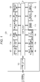
- the image forming apparatus 100 is configured by including a control unit 101, a communication unit 102, an operation display unit 103, a storage unit 104, a paper feeding unit 105, a conveyance unit 110, a RIP processing unit 120, an image data storage unit 130, an image processing unit 140, an image forming unit 150, an output matter reading unit 160, a region setter 170, a region extractor 180 and a defect detector 190.
- control unit 101 controls each unit in the image forming apparatus 100 according to a control program.
- the control unit 101 serves as a control unit of the inspection apparatus to control inspection of the image according to an inspection program.
- the communication unit 102 communicates between the image forming apparatus 100 and other apparatuses (not illustrated).
- the operation display unit 103 receives operation input by a user and displays the status of the image forming apparatus 100.
- the storage unit 104 is configured with a nonvolatile memory and stores various settings.
- the paper feeding unit 105 feeds sheets accommodated in a paper feeding tray according to the timing of forming the image.
- the conveyance unit 110 conveys the sheet within the apparatus according to the timing of forming the image.
- the RIP processing unit 120 generates RIP image data (image forming image data) according to toner colors in the bitmap format by performing RIP processing on print data in a page description language format.
- the image data storage unit 130 stores the image forming image data and various data for the image to be formed.
- the image processing unit 140 executes various image processings, which are necessary to form the image, on the image forming image data.
- the image forming unit 150 forms the image on the sheet based on an image forming command and the image forming image data.
- the output matter reading unit 160 reads the image formed on the sheet and generates read image data.
- the region setter 170 sets a fixed region, in which the image is formed on the printed matter of the plurality of sheets with the same contents by using the same image forming image data, and a variable region, in which the image formed on the printed matter of the plurality of sheets with different contents by using different image forming image data, by information included in the image forming image data or designation by the user.
- the region extractor 180 extracts a first region (hereinafter referred to as a "character region”), in which a character is formed, and a second region, in which none of the character, line and painting are formed (hereinafter referred to as "background region").
- the defect detector 190 detects a defect by comparing the read image data of the printed matter of the plurality of sheets with the image forming image data or detects a defect by comparing the read image data of the printed matter of the plurality of sheets with reference read image data prepared in advance in the fixed region, and detects a defect by loss of a dot or presence of a dot in the read image data for the real image data of the printed matter of the plurality of sheets in the variable region.
- the image forming unit 150 is configured by having an image carrier 151, a charging unit 152, an exposure unit 153, a development unit 154, a transfer unit 155 and a fixing unit 156.
- a toner image is formed on the image carrier 151 as described later.
- the charging unit 152 charges the image carrier 151 with a predetermined potential.
- the exposure unit 153 forms an electrostatic latent image by exposing the charged image carrier 151 according to the image forming image data.
- the development unit 154 develops and converts the electrostatic latent image into the toner image.
- the transfer unit 155 transfers the toner image on the image carrier 151 to the sheet.
- the fixing unit 156 makes the toner image on the sheet stable by heat and pressure. Note that this configuration of the image forming unit 150 is one example and may form a multicolor image by using an intermediate transfer body. Moreover, the image forming unit 150 may be configured to turn over the sheet to form the image on both sides of the sheet.
- the output matter reading unit 160 is disposed on the downstream side of the sheet conveyance direction of the image forming unit 150 and is configured to read the image on the outputted sheet during the conveyance. Note that the output matter reading unit 160 may read one side of the sheet or may read both sides of the sheet at once. Moreover, when the output matter reading unit 160 is the one which reads one side, it is also possible to read both sides of the sheet by turning over the sheet.
- an inspection apparatus G can be configured with the control unit 101, the region setter 170, the region extractor 180 and the defect detector 190.
- Fig. 1 illustrates that the inspection apparatus G is incorporated in the image forming apparatus 100, the inspection apparatus G may be an inspection apparatus independent of the image forming apparatus 100.
- an off-line type inspection apparatus G which is not connected to the image forming apparatus 100 can be configured with the control unit 101, the output matter reading unit 160, the region setter 170, the region extractor 180 and the defect detector 190.
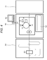
- an image forming system 1 including an inspection apparatus will be described in detail based on Figs. 3 and 4 .
- the image forming system 1 having a paper feeding apparatus 50, an image forming apparatus 100 and a reading apparatus 200 will be described.
- the image forming apparatus 100 is similar to that illustrated in Figs 1 and 2 but has no output matter reading unit. Moreover, the image forming system 1 may be configured to also use an output matter reading unit in the reading apparatus 200 although the image forming apparatus 100 has an output matter reading unit. Note that the same numerals are given to the same items in Figs. 1 and 2 and Figs. 3 and 4 , and redundant descriptions are omitted.
- the reading apparatus 200 is disposed on the downstream side of the sheet conveyance direction of the image forming apparatus 100.
- the reading apparatus 200 is configured by having a communication unit 202 and an output matter reading unit 260 and is configured to read the image on the outputted sheet during the conveyance.
- this reading apparatus 200 may be configured to have the output matter reading unit 260 in a post-processing apparatus having a post-processing unit (not illustrated) as a post unit of the image forming apparatus 100.
- the output matter reading unit 160 in Figs. 1 and 2 and the output matter reading unit 260 in Figs. 3 and 4 have line sensor type imaging elements whose longitudinal direction is a direction orthogonal to the sheet conveyance direction so that it becomes possible to read during the conveyance the image on the sheet outputted after the image is formed.
- the operation of the inspection apparatus will be described by explaining the operation of the image forming apparatus 100 with reference to the flowcharts and various explanatory diagrams. Note that the operation of the inspection apparatus is realized by the inspection program. Note that the operation of the image forming apparatus 100 incorporated with the output matter reading unit 160 is taken as a specific example herein, and the operation of the image forming system 1 is also substantially the same.
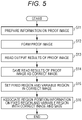
- control unit 101 sets or initializes each unit in the image forming apparatus 100 according to an image forming mode of a job to be executed. Moreover, the control unit 101 acquires a correct image (see Fig. 5 ) for the job to be executed before the start of forming the image.
- the control unit 101 prepares information on a proof image (step S11 in Fig. 5 ) and forms the proof image (step S12 in Fig. 5 ).
- the proof image is an image used to execute proof printing as trial printing before the image is actually formed and is an image substantially the same as an image used to actually form the image.
- control unit 101 controls the output matter reading unit 160 to execute the reading (step S13 in Fig. 5 ) and controls the image data storage unit 130 to save the read image acquired by the reading as the read image data (hereinafter referred to as "reference read image data) of the correct image (step S14 in Fig. 5 ).
- the region setter 170 received the instruction from the control unit 101 sets, in the correct image, the fixed region, in which the image is formed on the printed matter of the plurality of sheets with the same contents by using the same image forming image data, and the variable region, in which the image is formed on the printed matter of the plurality of sheets with different contents by using different image forming image data (step S15 in Fig. 5 ).
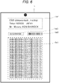
- variable printing when an image is formed on printed matter of a plurality of sheets, most of the image such as a main body is made common to be the fixed region (Fix1 in Fig. 6 ) and only a part of the image such as an address is changed to be the variable regions (Var1, Var2 and Var3 in Fig. 6 ) to be printed.
- the main body is the fixed region Fix1
- the address is the variable region Var1
- the address ID is the variable region Var2
- the barcode display of the address and ID is the variable region Var3.
- the region setter 170 may extract and set the distinction between the fixed region and the variable region from the job data or may display the correct image on the operation display unit 103 to set the distinction between the fixed region and the variable region by the instruction from the user. Then, the region setter 170 associates region position information on the fixed region and the variable region with the above correct image and saves the region position information in the image data storage unit 130 (step S16 in Fig. 5 ).
- control unit 101 After completion of setting the fixed region and the variable region based on the correct image by the region setter 170, the control unit 101 loads the image forming image data of the image to be actually formed (inspection target image) from a print preparation memory in the image data storage unit 130 (step S100 in Fig. 7 ).
- the feature of the present embodiment is that, as will be described later, it is unnecessary to compare, upon the inspection, image data of before and after the image is formed by detecting the loss (absence of dot) in the character region in the variable region and detecting defacement (presence of dot) in the background region in the variable region in the read image data of the formed inspection target image.
- the character region and the background region in the variable region of the inspection target image are identified based on the image forming image data as follows.
- the region extractor 180 received the instruction from the control unit 101 moves and fits a focused rectangular region against and to the variable region of the image forming image data of the inspection target image and extracts a maximum pixel value M included in that focused rectangular region (step S101 in Fig. 7 ).
- the reason that the focused rectangular region of a plurality of pixels x a plurality of pixels is used instead of performing identification for each pixel is to distinguish bleeding of the character due to toner scattering or the like around the character from the defacement.
- a focused rectangular region of 8 ⁇ 8 pixels is moved by every one pixel in the variable region of the image forming image data of the inspection target image while being fitted, and the maximum pixel value M included in the focused rectangular region is extracted.
- the region extractor 180 compares the extracted maximum pixel value M with a predetermined threshold value TH1 (step S102 in Fig. 7 ).
- the threshold value TH1 herein is used to identify the character, the background and the non-inspection target (e.g., a halftone image).
- the type of the region in the variable region withe reference to a minimum pixel value.
- the minimum value of the character region including even a small portion of the background is 0 and the character region does not become the character image, the possibility that the character image does not become the inspection target region becomes high in the case of a small character. Therefore, better results can be obtained by using the maximum pixel value.
- TH1 is set to about 200 or 250.
- the region is a halftone image other than the character region and the background region
- the region is identified as the non-inspection target region (S105, when TH1 ⁇ M > 0 in step S102 in Fig. 7 ).
- the region is identified by comparing M in the focused rectangular region with the threshold value TH1.
- a color character other than the black character is also the non-inspection target, but it is also possible to perform the inspection by identifying the color character as the character region.
- the region extractor 180 identifies the type of the inspection target region for the entire variable region (steps S106 and S107 in Fig. 7 ).
- Fig. 9A illustrates one example of the inspection target image.
- the alphabet "i" is illustrated as a specific example.
- Fig. 9B illustrates the focused rectangular region of the plurality of pixels described above. Then, the focused rectangular region in Fig. 9B is fitted to the inspection target image in Fig. 9A , and a region with M > TH1 even in one pixel in the focused rectangular region is identified as the character region. Therefore, the character regions are expanded to the outside of the character as indicated by the broken lines in Fig. 9C .
- the focused rectangular region of 8 ⁇ 8 pixels is used, expansion of seven pixels is made to the outside of the character.
- the regions indicated by hatching inside the broken lines in Fig. 9D are the character regions for the character in Fig. 9A .
- Fig. 10A illustrates another example of the inspection target image.
- the alphabet "P" is illustrated as a specific example.
- Fig. 10B illustrates the focused rectangular region of the plurality of pixels described above. Then, the focused rectangular region in Fig. 10B is fitted to the inspection target image in Fig. 10A , and a region with M > TH1 even in one pixel in the focused rectangular region is identified as the character region. Therefore, the character region is expanded to the outside of the character and to the inside of a loop of P as indicated by the broken lines in Fig. 10C .
- the focused rectangular region of 8 ⁇ 8 pixels is used, expansion of seven pixels is made to the outside and inside of the character. Note that the region indicated by hatching and surrounded by broken lines in Fig. 10D is the character region for the character in Fig. 10A .
- the region extractor 180 saves the region position information on the character region and the background region in the image data storage unit 130 (step S109 in Fig. 7 ).
- the control unit 101 controls the output matter reading unit 160 to generate the read image data (hereinafter referred to as "read image data of the inspection target image") by reading the printed matter on which the inspection target image is formed by the image forming unit 150 (step S110 in Fig. 7 ).
- the defect detector 190 received the instruction from the control unit 101 performs various filter processings on the read image data of the inspection target image in a set background region portion and acquires a paper color value W as the color of the sheet (step S111 in Fig. 7 ).
- filter processings such as median filter processing and moving average filter processing
- filter processings other than the median filter processing and the moving average filter processing can also be used as the filter processings.
- the paper color value W can be acquired by performing the filter processings not only on the background region but also on the entire variable region or the entire sheet. Since the area of the paper surface without the character is larger than the area of the character dots occupying on the paper surface, it is possible to acquire a value close to the paper color even when the filter processings are performed on the entire region.
- the defect detector 190 acquires a pixel value A of a focused pixel per pixel for all the regions in the read image data of the inspection target image and executes the following defect detection processings (steps S112 to S127 in Fig. 7 ).
- the defect detector 190 determines whether the focused pixel with the acquired pixel value A is the variable region or the background region with reference to the region position information (step S113 in Fig. 7 ). If the focused pixel is determined as the fixed region (NO in step S113 in Fig. 7 ), the defect detector 190 compares the pixel value A with a pixel value of a pixel corresponding to the focused pixel between the reference read image data saved in the image data storage unit 130 and the read image data of the inspection target image (step S114 in Fig. 7 ).
- step S116 in Fig. 7 the defect detector 190 determines that the focused pixel of the read image data of the inspection target image belongs to a normal image.
- step S116 in Fig. 7 the defect detector 190 determines that the focused pixel of the read image data of the inspection target image belongs to a defacement image.
- the defect detector 190 determines that the focused pixel of the read image data of the inspection target image belongs to a loss image (step S119 in Fig. 7 ).
- the defect detector 190 moves to a next focused pixel and perform the same processings so as to detect the presence or absence of the defect of the focused pixel for all the regions in the read image data of the inspection target image (step S127 in Fig. 7 ). Note that, since the focused pixel belongs to the fixed region in the above case, it is possible to easily compare the focused pixel of the read image data of the inspection target image with the corresponding pixel of the reference read image data prepared in advance.
- the defect detector 190 determines whether the focused pixel with the acquired pixel value A is the variable region or the background region with reference to the region position information (step S113 in Fig. 7 ). If the focused pixel is determined as the variable region (YES in step S113 in Fig. 7 ), the defect detector 190 detects whether the focused pixel is normal, the defacement, or a loss candidate by comparing the pixel value A with the threshold value (steps S 122 and S 124 in Fig. 7 ) depending on whether the focused pixel is the character region or the background region (steps S120 and S121 in Fig. 7 ).
- the defect detector 190 determines that the focused pixel is a loss image candidate in which a dot constituting the character is lost (step S123 in Fig. 7 ). If the difference A-W between the pixel value A of the focused pixel and the paper color value W is equal to or greater than the threshold value TH2 (NO in step S122 in Fig. 7 ), the defect detector 190 determines that the focused pixel is the normal image in which the dot constituting the character is not lost (step S116 in Fig. 7 ).
- the threshold value TH2 may be any value close to the paper color value (minimum value). For example, by setting the threshold value TH2 to a value of about 5% or 10% close to the paper color value in a case where the maximum value of the density of the character is set to 100% and the paper color value is set to 0%, it is possible to accurately determine the loss of the character.
- the defect detector 190 determines that the focused pixel is a defacement image in which some density (defacement) is present in the background (step S125 in Fig. 7 ). If the difference A-W between the pixel value A of the focused pixel and the paper color value W is equal to or less than the threshold value TH3 (NO in step S124 in Fig.
- the defect detector 190 determines that the focused pixel is the normal image in which a stain is not attached to the background (step S116 in Fig. 7 ).
- the threshold value TH3 may be any value capable of distinguishing visually recognizable defacement from a normal background. For example, by setting the threshold value TH3 to a value about 50% or 25 % of a case where the maximum value of the density of the character is set to 100%, it is possible to perform secure determination. Note that, if this threshold value TH3 is small, it is possible to strictly check the defacement.
- the defect detector 190 determines that the focused pixel is the normal image since the loss of the character and the defacement of the background are not present (step S116 in Fig. 7 ).
- a character region defect detector for detecting a defect in the character region and a background region defect detector for detecting a defect in the background region may be provided in the defect detector 190.
- the defect detector 190 moves to a next focused pixel and perform the same processings so as to detect the presence or absence of the defect of the focused pixel for all the regions in the read image data of the inspection target image (step S127 in Fig. 7 ).
- the character region is expanded to include the periphery of the character as indicated by the broken lines in Figs. 9A to 9D and Figs. 10A to 10D as described above so as not to erroneously detect the bleeding of the character as the defacement of the background. Therefore, a case where s dot is not present even in one pixel of the character region is not defined as the loss image but set as the loss image candidate, and a case a series of loss image candidates are present in a large number of pixels (area) with values equal to or greater than a threshold value TH4 is decided as the loss image in the character region (step S128 in Fig. 7 ).
- the threshold value TH4 depends on the size of the character desired to be decided as the loss image, a size changing parameter is prepared. For example, when the loss of only the upper point portion of the character "i" in Fig. 9A is desired to be detected, the threshold value TH4 is set to be smaller according to the number of pixels in the upper point portion in Fig. 9D . When the loss of the entire character "i" in Fig. 9A is desired to be detected, the desired loss can be detected by setting the threshold value TH4 to be greater according to the total number of pixels in Fig. 9D . Moreover, the threshold value TH4 is desired to be changed according to the size of the character (number of points) in conjunction for both cases of the portion of the character and the entire character.
- the defect detector 190 saves the detection results in the image data storage unit 130 as well as notifies the control unit 101 (step S129 in Fig. 7 ).
- control unit 101 received the defect detection results changes a discharge tray of the sheet with the inspection target image, informs the operation display unit 103 of the abnormality and performs various other controls when the inspection target image is determined to be a defect.
- the focused pixel is the variable region as described above, the corresponding pixels of the reference read image data or the image forming image data and the read image data of the inspection target image are not compared with each other, but only the pixel values of the read image data of the inspection target image are compared with the threshold values. Thus, it is possible to efficiently and accurately perform the inspection with less computations.
- the region extractor 180 identifies the character region and the background region in the variable region based on the image forming image data of the inspection target image (steps S101 to S109 in Fig. 7 ), by dividing the image forming image data of the inspection target image into division regions each with N pixels ⁇ N pixels, determining a predetermined pixel value in each of the division regions as a representative value of each of the division regions, collecting the representative value of each of the division regions to generate reduced image forming image data in which the image forming image data is reduced to 1/N in length and width, it is possible to identify the character region and the background region based on this reduced image forming image data.
- the predetermined pixel value is any one of the minimum value, the maximum value, the average value, the median value, the mode or the like in each of the division regions.
- the region extractor 180 identifies the character region and the background region in the variable region by using the reduced image forming image data in this manner so that the computation time can be shortened. Therefore, even when the image forming image data of the inspection target image is high definition and large in size, it is possible to deal with the data easily.
- variable printing in which the fixed region and the variable region are present, has been taken as a specific example.
- the processings illustrated in Fig. 5 and the processings in step S113, step S114, step S115, step S116, step S118 and step S119 in Fig. 7 are omitted.
- An inspection apparatus (G) for inspecting printed matter on which an image is formed comprising: a region extractor (180) that extracts a first region, in which a character is formed, and a second region, in which the character is not formed, with reference to image forming image data used to form the image; and a defect detector (190) that detects a defect in the first region and a defect in the second region in read image data obtained by reading the printed matter on which the image is formed by the image forming image data, wherein the defect detector (190) includes:
- E2 The inspection apparatus (G) according to E1, wherein the region extractor (180) extracts a region, in which a pixel whose pixel value of at least one color constituting the image forming image data is equal to or greater than a predetermined threshold value is present, as the first region.
- E3 The inspection apparatus (G) according to E1 or E2, wherein the region extractor (180) extracts a region, in which a pixel whose pixel values of all colors constituting the image forming image data are 0 is present, as the second region.
- E4 The inspection apparatus (G) according to E3, wherein the region extractor (180) extracts a region, in which a marked pixel has pixel values of 0 for all the colors constituting the image forming image data and peripheral pixels of the marked pixel also have pixel values of 0 for all the colors, as the second region.
- E5 The inspection apparatus (G) according to any one of El to E3, wherein the first region defect detector detects, in the first region, a pixel with a density equal to a density of the second region in the read image data as the defect due to the loss.
- E6 The inspection apparatus (G) according to E5, wherein the first region defect detector detects loss of a predetermined number or more of consecutive dots as the defect in the first region.
- E7 The inspection apparatus (G) according to any one of El to E6, wherein the second region defect detector detects, in the second region, a pixel, which has a density greater than a paper average density obtained from the read image data as the defect.
- E8 The inspection apparatus (G) according to any one of El to E7, wherein the region extractor (180) divides the image forming image data into division regions each with N pixels ⁇ N pixels, determines a predetermined pixel value in each of the division regions as a representative value of each of the division regions, collects the representative value of each of the division regions to generate reduced image forming image data in which the image forming image data is reduced to 1/N in length and width, and extracts the first region and the second region with reference to the reduced image forming image data.
- the region extractor (180) divides the image forming image data into division regions each with N pixels ⁇ N pixels, determines a predetermined pixel value in each of the division regions as a representative value of each of the division regions, collects the representative value of each of the division regions to generate reduced image forming image data in which the image forming image data is reduced to 1/N in length and width, and extracts the first region and the second region with reference to the reduced image forming image data.
- the inspection apparatus (G) according to any one of El to E8, further comprising a region setter (170) that sets a fixed region, in which the image is formed on the printed matter of a plurality of sheets with same contents by using same image forming image data, and a variable region, in which the image is formed on the printed matter of the plurality of the sheets with different contents by using different image forming image data, wherein the defect detector (190) detects the defect by comparing the read image data of the printed matter of the plurality of the sheets with the image forming image data or detects the defect by comparing the read image data of the printed matter of the plurality of the sheets with reference read image data prepared in advance in the fixed region, and detects the defect by the loss of the dot or the presence of the dot in the read image data for the read image data of the printed matter of the plurality of the sheets in the variable region.
- the defect detector (190) detects the defect by comparing the read image data of the printed matter of the plurality of the sheets with the image forming image data or detect
- E10 An inspection program that controls an inspection apparatus (G) for inspecting printed matter on which an image is formed and including: a region extractor (180) that extracts a first region, in which a character is formed, and a second region, in which the character is not formed, with reference to image forming image data used to form the image; and a defect detector (190) that detects a defect in the first region and a defect in the second region in read image data obtained by reading the printed matter on which the image is formed by the image forming image data, the program causing a computer of the inspection apparatus (G) to function such that the defect detector (190) detects loss of a dot in the first region in the read image data as the defect and detects presence of a dot with a density equal to or greater than a predetermined density in the second region in the read image data as the defect.
Landscapes
- Engineering & Computer Science (AREA)
- Health & Medical Sciences (AREA)
- Signal Processing (AREA)
- Multimedia (AREA)
- General Health & Medical Sciences (AREA)
- Biomedical Technology (AREA)
- General Physics & Mathematics (AREA)
- Theoretical Computer Science (AREA)
- Physics & Mathematics (AREA)
- Computer Vision & Pattern Recognition (AREA)
- Quality & Reliability (AREA)
- Image Processing (AREA)
- Investigating Materials By The Use Of Optical Means Adapted For Particular Applications (AREA)
- Image Analysis (AREA)
- Cleaning In Electrography (AREA)
- Control Or Security For Electrophotography (AREA)
- Facsimiles In General (AREA)
- Accessory Devices And Overall Control Thereof (AREA)
Abstract
Description
- The present invention relates to an inspection apparatus and an inspection program for efficiently and accurately inspecting printed matter on which an image is formed, and, particularly, to a technology capable of efficiently and accurately performing inspection even when an image is formed on printed matter of a plurality of sheets with different contents by using different image forming image data.
- There is an image forming apparatus in which a reading unit is subsequently connected to an image forming unit which forms an image on a sheet, and the image formed on the sheet is read by the reading unit. Such an image forming apparatus is sometimes used for the purpose of detecting an abnormal sheet (waste paper), on which an abnormal image (waste image) is formed, with reference to the reading results after the image is formed.
- Generally in print processing, proof printing is performed as trial printing before mass printing is performed, and the printing results are checked for the presence or absence of abnormality. A read image obtained by reading the output matter at this time is saved as a correct image. Then, in abnormal image detection at the time of final printing, it is usual to compare the correct image prepared in advance with a read image printed at this time and define the read image as an abnormal image if there is a difference.
- Incidentally, printing called "variable printing" is sometimes performed, in which most of an image is made common and only a part of the image is changed to be printed. For example, the variable printing is a printing method in which the main body is made common and only the address and name are changed such as in direct mails.
- In this type of variable printing, the common image portion can adopt a method of comparing the correct image with the read image described above. On the other hand, different contents are printed in a variable region such as an address or a name, which is different on each individual original sheet, for each sheet so that it is impossible to print and read a correct image in advance for preparation.
- Thereupon, image forming image data can be considered to be used as the correct image in the variable region. However, in the comparison between the image forming image data generated by digital data of CMYK which are the basic colors of toner and read image data of the RGB printing results outputted from a scanner, the color spaces and the degrees of blurring of the images are totally different from each other. Thus, the detection precision has been known to be decreased in the comparison between the same read images.
- Moreover, there is a problem that using the comparison with the image forming image data including the common region in which the read image can be prepared in advance is disadvantageous in terms of precision.
- As this type of technology, various relating proposals have been made in
JP 2014-134401 A JP 2013-197860 A JP 2013-179546 A JP 2012-000876 A - As for the comparison of image data,
JP 2014-134401 A -
JP 2013-197860 A -
JP 2013-179546 A -
JP 2012-000876 A - Incidentally, as described above, a method of preparing a correct image in advance and performing a difference comparison with an inspection target image to determine the presence or absence of abnormality is usual for the inspection of printed image. On the other hand, in the case of variable printing, an image is different for every output so that a correct image cannot be prepared in advance. Therefore, in this case, the image forming image data and the read image data are compared.
- The Image forming image data have output resolutions of CMYK which are toner colors. On the other hand, since the printed image is subjected to halftone processing such as screen processing and further printed, the edge portion is usually blurred as compared with the image forming image data. Moreover, by reading these printing results with the reading unit, the printing results become image data in RGB format, and the resolution also depends on the scan setting of the reading unit. In order to compare images with considerably different characteristics in this manner, various processings such as color matching, resolution conversion and filter blurring processing are performed for the comparison. When these processings are executed by software, the degree of freedom is high, but the processing time is long. On the other hand, when these processings are executed by hardware, the costs increase. Furthermore, there may be a case that, due to factors such as different color tones depending on the type of paper even after the processings, it is impossible to perform the conversion into completely the same characteristics for the comparison and expect high precision.
- Therefore, it is difficult to efficiently and accurately inspect printed images when the images are formed on printed matter of a plurality of sheets with different contents by using different image forming image data even by using any one of the technologies described above in
JP 2014-134401 A JP 2013-197860 A JP 2013-179546 A JP 2012-000876 A - An object of the present invention is to realize an inspection apparatus and an inspection program capable of efficiently and accurately performing inspection even when images are formed on printed matter of a plurality of sheets with different contents by using different image forming image data.
- To achieve the abovementioned object, according to an aspect of the present invention, an inspection apparatus for inspecting printed matter on which an image is formed, reflecting one aspect of the present invention comprises: a region extractor that extracts a first region, in which a character is formed, and a second region, in which the character is not formed, with reference to image forming image data used to form the image; and a defect detector that detects a defect in the first region and a defect in the second region in read image data obtained by reading the printed matter on which the image is formed by the image forming image data, wherein the defect detector includes: a first region defect detector that detects loss of a dot in the first region in the read image data; and a second region defect detector that detects presence of a dot with a density equal to or greater than a predetermined density in the second region in the read image data.
- The advantages and features provided by one or more embodiments of the invention will become more fully understood from the detailed description given hereinbelow and the appended drawings which are given by way of illustration only, and thus are not intended as a definition of the limits of the present invention:
-
Fig. 1 is a configuration diagram illustrating a configuration of an embodiment of the present invention; -
Fig. 2 is a configuration diagram illustrating a configuration of the embodiment of the present invention; -
Fig. 3 is a configuration diagram illustrating a configuration of an embodiment of the present invention; -
Fig. 4 is a configuration diagram illustrating a configuration of the embodiment of the present invention; -
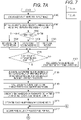
Fig. 5 is a flowchart illustrating the operation of the embodiment of the present invention; -
Fig. 6 is an explanatory diagram for explaining processings of the embodiment of the present invention; -
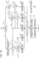
Fig. 7 is a flowchart illustrating the operation of the embodiment of the present invention; -
Fig. 8 is an explanatory diagram for explaining processings of the embodiment of the present invention; -
Figs. 9A to 9D are explanatory diagrams for explaining processings of the embodiment of the present invention; and -
Figs. 10A to 10D are explanatory diagrams for explaining processings of the embodiment of the present invention. - Hereinafter, one or more embodiments, in which printed matter can be efficiently and accurately inspected when an image is formed on the printed matter of a plurality of sheets with different contents, of the present invention will be described in detail with reference to the drawings. However, the scope of the invention is not limited to the disclosed embodiments.
- Herein, a configuration example of an
image forming apparatus 100 including an inspection apparatus will be described in detail based onFigs. 1 and2 . With theseFigs. 1 and2 , theimage forming apparatus 100 incorporated with an output matter reading unit will be described. - Herein, the
image forming apparatus 100 is configured by including acontrol unit 101, acommunication unit 102, anoperation display unit 103, astorage unit 104, apaper feeding unit 105, aconveyance unit 110, aRIP processing unit 120, an imagedata storage unit 130, animage processing unit 140, animage forming unit 150, an outputmatter reading unit 160, aregion setter 170, aregion extractor 180 and adefect detector 190. - Then, the
control unit 101 controls each unit in theimage forming apparatus 100 according to a control program. Note that, in the present embodiment, thecontrol unit 101 serves as a control unit of the inspection apparatus to control inspection of the image according to an inspection program. Thecommunication unit 102 communicates between theimage forming apparatus 100 and other apparatuses (not illustrated). Theoperation display unit 103 receives operation input by a user and displays the status of theimage forming apparatus 100. Thestorage unit 104 is configured with a nonvolatile memory and stores various settings. Thepaper feeding unit 105 feeds sheets accommodated in a paper feeding tray according to the timing of forming the image. Theconveyance unit 110 conveys the sheet within the apparatus according to the timing of forming the image. TheRIP processing unit 120 generates RIP image data (image forming image data) according to toner colors in the bitmap format by performing RIP processing on print data in a page description language format. The imagedata storage unit 130 stores the image forming image data and various data for the image to be formed. Theimage processing unit 140 executes various image processings, which are necessary to form the image, on the image forming image data. Theimage forming unit 150 forms the image on the sheet based on an image forming command and the image forming image data. The outputmatter reading unit 160 reads the image formed on the sheet and generates read image data. Theregion setter 170 sets a fixed region, in which the image is formed on the printed matter of the plurality of sheets with the same contents by using the same image forming image data, and a variable region, in which the image formed on the printed matter of the plurality of sheets with different contents by using different image forming image data, by information included in the image forming image data or designation by the user. In the above variable region, theregion extractor 180 extracts a first region (hereinafter referred to as a "character region"), in which a character is formed, and a second region, in which none of the character, line and painting are formed (hereinafter referred to as "background region"). Thedefect detector 190 detects a defect by comparing the read image data of the printed matter of the plurality of sheets with the image forming image data or detects a defect by comparing the read image data of the printed matter of the plurality of sheets with reference read image data prepared in advance in the fixed region, and detects a defect by loss of a dot or presence of a dot in the read image data for the real image data of the printed matter of the plurality of sheets in the variable region. - Herein, as illustrated in
Fig. 2 , theimage forming unit 150 is configured by having animage carrier 151, a chargingunit 152, anexposure unit 153, adevelopment unit 154, atransfer unit 155 and afixing unit 156. Herein, a toner image is formed on theimage carrier 151 as described later. The chargingunit 152 charges theimage carrier 151 with a predetermined potential. Theexposure unit 153 forms an electrostatic latent image by exposing the chargedimage carrier 151 according to the image forming image data. Thedevelopment unit 154 develops and converts the electrostatic latent image into the toner image. Thetransfer unit 155 transfers the toner image on theimage carrier 151 to the sheet. The fixingunit 156 makes the toner image on the sheet stable by heat and pressure. Note that this configuration of theimage forming unit 150 is one example and may form a multicolor image by using an intermediate transfer body. Moreover, theimage forming unit 150 may be configured to turn over the sheet to form the image on both sides of the sheet. - Note that the output
matter reading unit 160 is disposed on the downstream side of the sheet conveyance direction of theimage forming unit 150 and is configured to read the image on the outputted sheet during the conveyance. Note that the outputmatter reading unit 160 may read one side of the sheet or may read both sides of the sheet at once. Moreover, when the outputmatter reading unit 160 is the one which reads one side, it is also possible to read both sides of the sheet by turning over the sheet. - Note that an inspection apparatus G can be configured with the
control unit 101, theregion setter 170, theregion extractor 180 and thedefect detector 190. AlthoughFig. 1 illustrates that the inspection apparatus G is incorporated in theimage forming apparatus 100, the inspection apparatus G may be an inspection apparatus independent of theimage forming apparatus 100. Furthermore, an off-line type inspection apparatus G which is not connected to theimage forming apparatus 100 can be configured with thecontrol unit 101, the outputmatter reading unit 160, theregion setter 170, theregion extractor 180 and thedefect detector 190. - Herein, a configuration example of an
image forming system 1 including an inspection apparatus will be described in detail based onFigs. 3 and4 . With theseFigs. 3 and4 , theimage forming system 1 having apaper feeding apparatus 50, animage forming apparatus 100 and areading apparatus 200 will be described. - Herein, the
image forming apparatus 100 is similar to that illustrated inFigs 1 and2 but has no output matter reading unit. Moreover, theimage forming system 1 may be configured to also use an output matter reading unit in thereading apparatus 200 although theimage forming apparatus 100 has an output matter reading unit. Note that the same numerals are given to the same items inFigs. 1 and2 andFigs. 3 and4 , and redundant descriptions are omitted. - Herein, the
reading apparatus 200 is disposed on the downstream side of the sheet conveyance direction of theimage forming apparatus 100. Thereading apparatus 200 is configured by having acommunication unit 202 and an outputmatter reading unit 260 and is configured to read the image on the outputted sheet during the conveyance. - Note that this
reading apparatus 200 may be configured to have the outputmatter reading unit 260 in a post-processing apparatus having a post-processing unit (not illustrated) as a post unit of theimage forming apparatus 100. - Note that the output
matter reading unit 160 inFigs. 1 and2 and the outputmatter reading unit 260 inFigs. 3 and4 have line sensor type imaging elements whose longitudinal direction is a direction orthogonal to the sheet conveyance direction so that it becomes possible to read during the conveyance the image on the sheet outputted after the image is formed. - Hereinafter, the operation of the inspection apparatus will be described by explaining the operation of the
image forming apparatus 100 with reference to the flowcharts and various explanatory diagrams. Note that the operation of the inspection apparatus is realized by the inspection program. Note that the operation of theimage forming apparatus 100 incorporated with the outputmatter reading unit 160 is taken as a specific example herein, and the operation of theimage forming system 1 is also substantially the same. - At the start of forming an image, the
control unit 101 sets or initializes each unit in theimage forming apparatus 100 according to an image forming mode of a job to be executed. Moreover, thecontrol unit 101 acquires a correct image (seeFig. 5 ) for the job to be executed before the start of forming the image. - The
control unit 101 prepares information on a proof image (step S11 inFig. 5 ) and forms the proof image (step S12 inFig. 5 ). Herein, the proof image is an image used to execute proof printing as trial printing before the image is actually formed and is an image substantially the same as an image used to actually form the image. - After this proof image is formed, the
control unit 101 controls the outputmatter reading unit 160 to execute the reading (step S13 inFig. 5 ) and controls the imagedata storage unit 130 to save the read image acquired by the reading as the read image data (hereinafter referred to as "reference read image data) of the correct image (step S14 inFig. 5 ). - Herein, the
region setter 170 received the instruction from thecontrol unit 101 sets, in the correct image, the fixed region, in which the image is formed on the printed matter of the plurality of sheets with the same contents by using the same image forming image data, and the variable region, in which the image is formed on the printed matter of the plurality of sheets with different contents by using different image forming image data (step S15 inFig. 5 ). - Note that the fixed region and the variable region will be described with reference to
Fig. 6 . For example, in a printing method called "variable printing", as illustrated inFig. 6 , when an image is formed on printed matter of a plurality of sheets, most of the image such as a main body is made common to be the fixed region (Fix1 inFig. 6 ) and only a part of the image such as an address is changed to be the variable regions (Var1, Var2 and Var3 inFig. 6 ) to be printed. In the example illustrated inFig. 6 , the main body is the fixed region Fix1, the address is the variable region Var1, the address ID is the variable region Var2, and the barcode display of the address and ID is the variable region Var3. - Note that the
region setter 170 may extract and set the distinction between the fixed region and the variable region from the job data or may display the correct image on theoperation display unit 103 to set the distinction between the fixed region and the variable region by the instruction from the user. Then, theregion setter 170 associates region position information on the fixed region and the variable region with the above correct image and saves the region position information in the image data storage unit 130 (step S16 inFig. 5 ). - After completion of setting the fixed region and the variable region based on the correct image by the
region setter 170, thecontrol unit 101 loads the image forming image data of the image to be actually formed (inspection target image) from a print preparation memory in the image data storage unit 130 (step S100 inFig. 7 ). - Note that, the feature of the present embodiment is that, as will be described later, it is unnecessary to compare, upon the inspection, image data of before and after the image is formed by detecting the loss (absence of dot) in the character region in the variable region and detecting defacement (presence of dot) in the background region in the variable region in the read image data of the formed inspection target image. Thus, the character region and the background region in the variable region of the inspection target image are identified based on the image forming image data as follows.
- To identify the character region, background region and non-inspection target region, which is neither the character region nor the background region, in the set variable region, the
region extractor 180 received the instruction from thecontrol unit 101 moves and fits a focused rectangular region against and to the variable region of the image forming image data of the inspection target image and extracts a maximum pixel value M included in that focused rectangular region (step S101 inFig. 7 ). - Note that the reason that the focused rectangular region of a plurality of pixels x a plurality of pixels is used instead of performing identification for each pixel is to distinguish bleeding of the character due to toner scattering or the like around the character from the defacement. Thereupon, in consideration of the size of the entire image, the size of the character, and the like, for example, a focused rectangular region of 8 × 8 pixels is moved by every one pixel in the variable region of the image forming image data of the inspection target image while being fitted, and the maximum pixel value M included in the focused rectangular region is extracted.
- Herein, the
region extractor 180 compares the extracted maximum pixel value M with a predetermined threshold value TH1 (step S102 inFig. 7 ). Note that the threshold value TH1 herein is used to identify the character, the background and the non-inspection target (e.g., a halftone image). Note that is also possible to identify the type of the region in the variable region withe reference to a minimum pixel value. However, since the minimum value of the character region including even a small portion of the background is 0 and the character region does not become the character image, the possibility that the character image does not become the inspection target region becomes high in the case of a small character. Therefore, better results can be obtained by using the maximum pixel value. - Thereupon, as illustrated in the table in
Fig. 8 , when each toner color of Y, M, C and K takes a value of 0 to 255, the output gradation of the character image is normally set to be darker in most cases, so TH1 is set to about 200 or 250. If M > TH1, the region has a black character or a black line and is identified as the character region (S103, when M > TH1 in step S102 inFig. 7 ). If M = 0 in each color, the region is identified as a background region candidate (S104, when M = 0 in step S102 inFig. 7 ). If the region is a halftone image other than the character region and the background region, the region is identified as the non-inspection target region (S105, when TH1 ≥ M > 0 in step S102 inFig. 7 ). Thus, it is possible to identify the region by comparing M in the focused rectangular region with the threshold value TH1. Note that, in the case ofFig. 8 , a color character other than the black character is also the non-inspection target, but it is also possible to perform the inspection by identifying the color character as the character region. - As described above, by moving the focused rectangular region by every one pixel in the variable region of the image forming image data of the inspection target image while being fitted and extracting the maximum pixel value M included in the focused rectangular region, the
region extractor 180 identifies the type of the inspection target region for the entire variable region (steps S106 and S107 inFig. 7 ). -
Fig. 9A illustrates one example of the inspection target image. Herein, the alphabet "i" is illustrated as a specific example. Furthermore,Fig. 9B illustrates the focused rectangular region of the plurality of pixels described above. Then, the focused rectangular region inFig. 9B is fitted to the inspection target image inFig. 9A , and a region with M > TH1 even in one pixel in the focused rectangular region is identified as the character region. Therefore, the character regions are expanded to the outside of the character as indicated by the broken lines inFig. 9C . Herein, when the focused rectangular region of 8 × 8 pixels is used, expansion of seven pixels is made to the outside of the character. Note that the regions indicated by hatching inside the broken lines inFig. 9D are the character regions for the character inFig. 9A . -
Fig. 10A illustrates another example of the inspection target image. Herein, the alphabet "P" is illustrated as a specific example. Furthermore,Fig. 10B illustrates the focused rectangular region of the plurality of pixels described above. Then, the focused rectangular region inFig. 10B is fitted to the inspection target image inFig. 10A , and a region with M > TH1 even in one pixel in the focused rectangular region is identified as the character region. Therefore, the character region is expanded to the outside of the character and to the inside of a loop of P as indicated by the broken lines inFig. 10C . Herein, when the focused rectangular region of 8 × 8 pixels is used, expansion of seven pixels is made to the outside and inside of the character. Note that the region indicated by hatching and surrounded by broken lines inFig. 10D is the character region for the character inFig. 10A . - Moreover, as described above, there are cases where the bleeding of the character image is present near the edges of the character region due to printing and the character image is present in an image region with nothing due to distortion at the time of printing. Thus, it is necessary to have a certain amount of margin. Thereupon, for the background region candidate identified as described above (step S104 in
Fig. 7 ), when the maximum value = 0 in the focused rectangular region and L number of the focused rectangular regions therearound (when the peripheral regions are also the background region candidates), the focused rectangular region which is the background region candidate is decided as the background region (step S108 inFig. 7 ). - After the character region and the background region are identified in the variable region in the inspection target image as described above, the
region extractor 180 saves the region position information on the character region and the background region in the image data storage unit 130 (step S109 inFig. 7 ). - Then, after the
region extractor 180 identifies the character region and the background region in the variable region based on the image forming image data of the inspection target image (steps S101 to S109 inFig. 7 ), thecontrol unit 101 controls the outputmatter reading unit 160 to generate the read image data (hereinafter referred to as "read image data of the inspection target image") by reading the printed matter on which the inspection target image is formed by the image forming unit 150 (step S110 inFig. 7 ). - Herein, the
defect detector 190 received the instruction from thecontrol unit 101 performs various filter processings on the read image data of the inspection target image in a set background region portion and acquires a paper color value W as the color of the sheet (step S111 inFig. 7 ). Herein, by performing filter processings such as median filter processing and moving average filter processing on the background region portion of the read image data of the inspection target image, it is possible to remove noise components and acquire the paper color value W as the color of the sheet used to form the image. Note that filter processings other than the median filter processing and the moving average filter processing can also be used as the filter processings. - Moreover, the paper color value W can be acquired by performing the filter processings not only on the background region but also on the entire variable region or the entire sheet. Since the area of the paper surface without the character is larger than the area of the character dots occupying on the paper surface, it is possible to acquire a value close to the paper color even when the filter processings are performed on the entire region.
- Furthermore, the
defect detector 190 acquires a pixel value A of a focused pixel per pixel for all the regions in the read image data of the inspection target image and executes the following defect detection processings (steps S112 to S127 inFig. 7 ). - Herein, the
defect detector 190 determines whether the focused pixel with the acquired pixel value A is the variable region or the background region with reference to the region position information (step S113 inFig. 7 ). If the focused pixel is determined as the fixed region (NO in step S113 inFig. 7 ), thedefect detector 190 compares the pixel value A with a pixel value of a pixel corresponding to the focused pixel between the reference read image data saved in the imagedata storage unit 130 and the read image data of the inspection target image (step S114 inFig. 7 ). - If there is no difference between the pixel value as a result of the comparison (NO in step S115 in
Fig. 7 ), thedefect detector 190 determines that the focused pixel of the read image data of the inspection target image belongs to a normal image (step S116 inFig. 7 ). On the other hand, if there is a difference between the pixel values as a result of the comparison (YES in step S115 inFig. 7 ) and a dot is not present in the correct image (YES in step S117 inFig. 7 ), thedefect detector 190 determines that the focused pixel of the read image data of the inspection target image belongs to a defacement image (step S118 inFig. 7 ). Furthermore, if there is a difference between the pixel values as a result of the comparison (YES in step S115 inFig. 7 ) and a dot is present in the correct image (NO in step S117 inFig. 7 ), thedefect detector 190 determines that the focused pixel of the read image data of the inspection target image belongs to a loss image (step S119 inFig. 7 ). - After the presence or absence of the defect of the focused pixel in the fixed region is detected by the determinations described above (steps S116, S118 and S119 in
Fig. 7 ), thedefect detector 190 moves to a next focused pixel and perform the same processings so as to detect the presence or absence of the defect of the focused pixel for all the regions in the read image data of the inspection target image (step S127 inFig. 7 ). Note that, since the focused pixel belongs to the fixed region in the above case, it is possible to easily compare the focused pixel of the read image data of the inspection target image with the corresponding pixel of the reference read image data prepared in advance. - On the other hand, the
defect detector 190 determines whether the focused pixel with the acquired pixel value A is the variable region or the background region with reference to the region position information (step S113 inFig. 7 ). If the focused pixel is determined as the variable region (YES in step S113 inFig. 7 ), thedefect detector 190 detects whether the focused pixel is normal, the defacement, or a loss candidate by comparing the pixel value A with the threshold value (steps S 122 and S 124 inFig. 7 ) depending on whether the focused pixel is the character region or the background region (steps S120 and S121 inFig. 7 ). - That is, if the focused pixel is the character region in the variable region (YES in step S113 and YES in step S120 in
Fig. 7 ) and a difference A-W between the pixel value A of the focused pixel and the paper color value W is less than a threshold value TH2 (YES in step S122 inFig. 7 ), thedefect detector 190 determines that the focused pixel is a loss image candidate in which a dot constituting the character is lost (step S123 inFig. 7 ). If the difference A-W between the pixel value A of the focused pixel and the paper color value W is equal to or greater than the threshold value TH2 (NO in step S122 inFig. 7 ), thedefect detector 190 determines that the focused pixel is the normal image in which the dot constituting the character is not lost (step S116 inFig. 7 ). - Note that, by setting the threshold value TH2 to any value between the density of the character and the paper color value, for example, a value about 50% of a case where the maximum value of the density of the character is set to 100%, it is possible to perform secure determination. Moreover, the threshold value TH2 may be any value close to the paper color value (minimum value). For example, by setting the threshold value TH2 to a value of about 5% or 10% close to the paper color value in a case where the maximum value of the density of the character is set to 100% and the paper color value is set to 0%, it is possible to accurately determine the loss of the character.
- Furthermore, when the paper color value W is calculated by averaging the entire sheet or the entire variable region in step S111, it is also possible to directly apply the paper color value W to this threshold value TH2.
- Further, if the focused pixel is the background region in the variable region (YES in step S113, NO in step S120 and YES in step S121 in
Fig. 7 ) and the difference A-W between the pixel value A of the focused pixel and the paper color value W is greater than a threshold value TH3 (YES in step S124 inFig. 7 ), thedefect detector 190 determines that the focused pixel is a defacement image in which some density (defacement) is present in the background (step S125 inFig. 7 ). If the difference A-W between the pixel value A of the focused pixel and the paper color value W is equal to or less than the threshold value TH3 (NO in step S124 inFig. 7 ), thedefect detector 190 determines that the focused pixel is the normal image in which a stain is not attached to the background (step S116 inFig. 7 ). Note that the threshold value TH3 may be any value capable of distinguishing visually recognizable defacement from a normal background. For example, by setting the threshold value TH3 to a value about 50% or 25 % of a case where the maximum value of the density of the character is set to 100%, it is possible to perform secure determination. Note that, if this threshold value TH3 is small, it is possible to strictly check the defacement. - Moreover, if the focused pixel in the variable region is neither the character region nor the background region in the variable region (YES in step S113, NO in step S120 and NO in step S121 in
Fig. 7 ), thedefect detector 190 determines that the focused pixel is the normal image since the loss of the character and the defacement of the background are not present (step S116 inFig. 7 ). - Note that, to detect the defect by the
defect detector 190 as described above, a character region defect detector for detecting a defect in the character region and a background region defect detector for detecting a defect in the background region may be provided in thedefect detector 190. - After the presence or absence of the defect of the focused pixel in the variable region is detected by the determinations described above (steps S116, S123 and S125 in
Fig. 7 ), thedefect detector 190 moves to a next focused pixel and perform the same processings so as to detect the presence or absence of the defect of the focused pixel for all the regions in the read image data of the inspection target image (step S127 inFig. 7 ). - Note that the character region is expanded to include the periphery of the character as indicated by the broken lines in
Figs. 9A to 9D andFigs. 10A to 10D as described above so as not to erroneously detect the bleeding of the character as the defacement of the background. Therefore, a case where s dot is not present even in one pixel of the character region is not defined as the loss image but set as the loss image candidate, and a case a series of loss image candidates are present in a large number of pixels (area) with values equal to or greater than a threshold value TH4 is decided as the loss image in the character region (step S128 inFig. 7 ). Herein, since the threshold value TH4 depends on the size of the character desired to be decided as the loss image, a size changing parameter is prepared. For example, when the loss of only the upper point portion of the character "i" inFig. 9A is desired to be detected, the threshold value TH4 is set to be smaller according to the number of pixels in the upper point portion inFig. 9D . When the loss of the entire character "i" inFig. 9A is desired to be detected, the desired loss can be detected by setting the threshold value TH4 to be greater according to the total number of pixels inFig. 9D . Moreover, the threshold value TH4 is desired to be changed according to the size of the character (number of points) in conjunction for both cases of the portion of the character and the entire character. - As described above, after the defect detection is completed for the entire character region and background region in the variable region in the inspection target image, the
defect detector 190 saves the detection results in the imagedata storage unit 130 as well as notifies the control unit 101 (step S129 inFig. 7 ). - Note that the
control unit 101 received the defect detection results changes a discharge tray of the sheet with the inspection target image, informs theoperation display unit 103 of the abnormality and performs various other controls when the inspection target image is determined to be a defect. - Note that, when the focused pixel is the variable region as described above, the corresponding pixels of the reference read image data or the image forming image data and the read image data of the inspection target image are not compared with each other, but only the pixel values of the read image data of the inspection target image are compared with the threshold values. Thus, it is possible to efficiently and accurately perform the inspection with less computations.
- Also at this time, since the character region and the background region in the variable region are identified by the pixel values, it is possible to accurately identify each region at high speed.
- Also at this time, by detecting a pixel with a density is equal to that of the background region in the read image data as the defect due to the loss, it is possible to accurately detect the defect of the loss of the character in the character region.
- Moreover, by detecting the loss of a predetermined number or more of consecutive dots as the defect in the character region in the variable region, it is possible to accurately detect the defect of the loss of the character in the character region.
- Furthermore, by detecting a pixel having a density greater than the paper average density obtained from the read image data as the defect in the background region in the variable region, it is possible to securely detect the stain as the presence of the dot in the background region.
- In the above embodiments, when the
region extractor 180 identifies the character region and the background region in the variable region based on the image forming image data of the inspection target image (steps S101 to S109 inFig. 7 ), by dividing the image forming image data of the inspection target image into division regions each with N pixels × N pixels, determining a predetermined pixel value in each of the division regions as a representative value of each of the division regions, collecting the representative value of each of the division regions to generate reduced image forming image data in which the image forming image data is reduced to 1/N in length and width, it is possible to identify the character region and the background region based on this reduced image forming image data. Note that the predetermined pixel value is any one of the minimum value, the maximum value, the average value, the median value, the mode or the like in each of the division regions. - The
region extractor 180 identifies the character region and the background region in the variable region by using the reduced image forming image data in this manner so that the computation time can be shortened. Therefore, even when the image forming image data of the inspection target image is high definition and large in size, it is possible to deal with the data easily. - In the above embodiments, the variable printing, in which the fixed region and the variable region are present, has been taken as a specific example. Herein, it is possible to obtain good results by applying the present embodiment to image data in which the entire image is equivalent to the variable region without the presence of the fixed region. In this case, the processings illustrated in
Fig. 5 and the processings in step S113, step S114, step S115, step S116, step S118 and step S119 inFig. 7 are omitted. Then, also in such a case, it is possible to detect the defects in the character region and the background region only by comparing the pixel values of the read image data of the inspection target image with the threshold values and possible to efficiently and accurately perform the inspection with less computations. - Although embodiments of the present invention have been described and illustrated in detail, the disclosed embodiments are made for purposes of illustration and example only and not limitation. The scope of the present invention should be interpreted by terms of the appended claims.
- E1: An inspection apparatus (G) for inspecting printed matter on which an image is formed, comprising: a region extractor (180) that extracts a first region, in which a character is formed, and a second region, in which the character is not formed, with reference to image forming image data used to form the image; and a defect detector (190) that detects a defect in the first region and a defect in the second region in read image data obtained by reading the printed matter on which the image is formed by the image forming image data, wherein the defect detector (190) includes:
- a first region defect detector that detects loss of a dot in the first region in the read image data; and
- a second region defect detector that detects presence of a dot with a density equal to or greater than a predetermined density in the second region in the read image data.
- E2: The inspection apparatus (G) according to E1, wherein the region extractor (180) extracts a region, in which a pixel whose pixel value of at least one color constituting the image forming image data is equal to or greater than a predetermined threshold value is present, as the first region.
- E3: The inspection apparatus (G) according to E1 or E2, wherein the region extractor (180) extracts a region, in which a pixel whose pixel values of all colors constituting the image forming image data are 0 is present, as the second region.
- E4: The inspection apparatus (G) according to E3, wherein the region extractor (180) extracts a region, in which a marked pixel has pixel values of 0 for all the colors constituting the image forming image data and peripheral pixels of the marked pixel also have pixel values of 0 for all the colors, as the second region.
- E5: The inspection apparatus (G) according to any one of El to E3, wherein the first region defect detector detects, in the first region, a pixel with a density equal to a density of the second region in the read image data as the defect due to the loss.
- E6: The inspection apparatus (G) according to E5, wherein the first region defect detector detects loss of a predetermined number or more of consecutive dots as the defect in the first region.
- E7: The inspection apparatus (G) according to any one of El to E6, wherein the second region defect detector detects, in the second region, a pixel, which has a density greater than a paper average density obtained from the read image data as the defect.
- E8: The inspection apparatus (G) according to any one of El to E7, wherein the region extractor (180) divides the image forming image data into division regions each with N pixels × N pixels, determines a predetermined pixel value in each of the division regions as a representative value of each of the division regions, collects the representative value of each of the division regions to generate reduced image forming image data in which the image forming image data is reduced to 1/N in length and width, and extracts the first region and the second region with reference to the reduced image forming image data.
- E9: The inspection apparatus (G) according to any one of El to E8, further comprising a region setter (170) that sets a fixed region, in which the image is formed on the printed matter of a plurality of sheets with same contents by using same image forming image data, and a variable region, in which the image is formed on the printed matter of the plurality of the sheets with different contents by using different image forming image data, wherein the defect detector (190) detects the defect by comparing the read image data of the printed matter of the plurality of the sheets with the image forming image data or detects the defect by comparing the read image data of the printed matter of the plurality of the sheets with reference read image data prepared in advance in the fixed region, and detects the defect by the loss of the dot or the presence of the dot in the read image data for the read image data of the printed matter of the plurality of the sheets in the variable region.
- E10: An inspection program that controls an inspection apparatus (G) for inspecting printed matter on which an image is formed and including: a region extractor (180) that extracts a first region, in which a character is formed, and a second region, in which the character is not formed, with reference to image forming image data used to form the image; and a defect detector (190) that detects a defect in the first region and a defect in the second region in read image data obtained by reading the printed matter on which the image is formed by the image forming image data, the program causing a computer of the inspection apparatus (G) to function such that the defect detector (190) detects loss of a dot in the first region in the read image data as the defect and detects presence of a dot with a density equal to or greater than a predetermined density in the second region in the read image data as the defect.
Claims (6)
- An inspection apparatus (G) for inspecting printed matter on which an image is formed, by comparing a read image on the printed matter with a correct image prepared in advance, comprising:an operation display unit (103), anda region setter (170) configured to set a variable region of a variable printing,wherein the variable region is set as a region on which the image is formed on the printed matter of the plurality of the sheets with different contents and wherein the variable region is set by the instruction from the user on the correct image displayed on an operation display unit (103).
- The inspection apparatus (G) according to claim 1,
wherein the region setter (170) is configured to display the correct image to set distinction between the fixed region and the variable region. - The inspection apparatus (G) according to claim 2,
wherein the fixed region is a region in which an image is formed on the printed matter of the plurality of sheets with same contents by using same image forming image data. - The inspection apparatus (G) according to claim 3,
wherein the region setter (170) associates region position information on the fixed region and the variable region with the correct image and saves the region position information in an image data storage unit (130). - The inspection apparatus (G) according to any one of claims 1 to 4,
wherein the read image data of the correct image is saved as reference read image data in the image data storage unit (130). - An inspection program that controls an inspection apparatus (G) for inspecting printed matter on which an image is formed, by comparing a read image on the printed matter with a correct image prepared in advance, comprising: a region setter (170) configured to set a variable region of a variable printing,
wherein the variable region is set as a region on which the image is formed on the printed matter of the plurality of the sheets with different contents and wherein the variable region is set by the instruction from the user on the correct image displayed on an operation display unit (103).
Applications Claiming Priority (2)
| Application Number | Priority Date | Filing Date | Title |
|---|---|---|---|
| JP2017078097A JP6569697B2 (en) | 2017-04-11 | 2017-04-11 | Inspection device and inspection program |
| EP18166090.3A EP3389010A1 (en) | 2017-04-11 | 2018-04-06 | Inspection apparatus and inspection program |
Related Parent Applications (1)
| Application Number | Title | Priority Date | Filing Date |
|---|---|---|---|
| EP18166090.3A Division EP3389010A1 (en) | 2017-04-11 | 2018-04-06 | Inspection apparatus and inspection program |
Publications (1)
| Publication Number | Publication Date |
|---|---|
| EP4095800A1 true EP4095800A1 (en) | 2022-11-30 |
Family
ID=62046635
Family Applications (2)
| Application Number | Title | Priority Date | Filing Date |
|---|---|---|---|
| EP18166090.3A Withdrawn EP3389010A1 (en) | 2017-04-11 | 2018-04-06 | Inspection apparatus and inspection program |
| EP22185198.3A Pending EP4095800A1 (en) | 2017-04-11 | 2018-04-06 | Inspection apparatus and inspection program |
Family Applications Before (1)
| Application Number | Title | Priority Date | Filing Date |
|---|---|---|---|
| EP18166090.3A Withdrawn EP3389010A1 (en) | 2017-04-11 | 2018-04-06 | Inspection apparatus and inspection program |
Country Status (4)
| Country | Link |
|---|---|
| US (1) | US10726556B2 (en) |
| EP (2) | EP3389010A1 (en) |
| JP (1) | JP6569697B2 (en) |
| CN (1) | CN108696663B (en) |
Families Citing this family (22)
| Publication number | Priority date | Publication date | Assignee | Title |
|---|---|---|---|---|
| US10620131B2 (en) * | 2015-05-26 | 2020-04-14 | Mitsubishi Electric Corporation | Detection apparatus and detection method |
| JP6992457B2 (en) * | 2017-12-05 | 2022-01-13 | コニカミノルタ株式会社 | Inspection equipment, image formation system, inspection method and program |
| JP7188930B2 (en) * | 2018-07-27 | 2022-12-13 | 株式会社Screenホールディングス | Engraving inspection device, engraving inspection method, and article inspection device |
| JP7099649B2 (en) * | 2018-10-23 | 2022-07-12 | コニカミノルタ株式会社 | Image inspection equipment and image inspection program |
| JP7115266B2 (en) * | 2018-12-03 | 2022-08-09 | コニカミノルタ株式会社 | IMAGE INSPECTION APPARATUS, IMAGE INSPECTION METHOD AND IMAGE INSPECTION PROGRAM |
| CN109615626B (en) * | 2018-12-11 | 2021-02-05 | 合肥工业大学 | Quality evaluation method for chip surface printing symbol structure defects |
| JP2020094878A (en) * | 2018-12-11 | 2020-06-18 | コニカミノルタ株式会社 | Foil-stamped print inspection apparatus, foil-stamped print inspection system, foil-stamped print inspection method, and program |
| JP7181377B2 (en) * | 2019-03-04 | 2022-11-30 | 富士フイルム株式会社 | Inspection method, program, inspection device, and printing device |
| JP7211169B2 (en) * | 2019-03-07 | 2023-01-24 | コニカミノルタ株式会社 | Image inspection device and image forming system |
| JP7156100B2 (en) * | 2019-03-07 | 2022-10-19 | コニカミノルタ株式会社 | IMAGE INSPECTION APPARATUS, IMAGE INSPECTION METHOD AND IMAGE INSPECTION PROGRAM |
| JP7163833B2 (en) * | 2019-03-15 | 2022-11-01 | コニカミノルタ株式会社 | Variable print image inspection system |
| JP7257232B2 (en) | 2019-04-17 | 2023-04-13 | コニカミノルタ株式会社 | IMAGE INSPECTION APPARATUS, IMAGE INSPECTION METHOD, IMAGE INSPECTION PROGRAM, AND IMAGE FORMING SYSTEM |
| EP3872756B1 (en) | 2020-02-26 | 2025-01-22 | Canon Kabushiki Kaisha | Image processing apparatus, image processing method, and computer program |
| JP7435040B2 (en) * | 2020-03-05 | 2024-02-21 | コニカミノルタ株式会社 | Image inspection equipment, image forming system, and control program |
| JP7517019B2 (en) * | 2020-09-18 | 2024-07-17 | 富士フイルムビジネスイノベーション株式会社 | Inspection device, image forming device, and inspection program |
| EP4084459B1 (en) * | 2021-04-28 | 2024-12-04 | Canon Kabushiki Kaisha | Image forming system for inspecting image formed on sheet |
| JP2023030810A (en) | 2021-08-24 | 2023-03-08 | キヤノン株式会社 | Inspection device, inspection system, control method for inspection device, and program |
| JP7729148B2 (en) * | 2021-09-28 | 2025-08-26 | 富士フイルムビジネスイノベーション株式会社 | Information processing device, information processing system, and program |
| US20230245298A1 (en) * | 2022-01-28 | 2023-08-03 | Canon Kabushiki Kaisha | Inspection apparatus, method of controlling the same, printing system, and storage medium |
| JP7148012B2 (en) * | 2022-02-17 | 2022-10-05 | コニカミノルタ株式会社 | Image inspection device and image inspection program |
| JP7176660B1 (en) | 2022-02-17 | 2022-11-22 | コニカミノルタ株式会社 | IMAGE INSPECTION APPARATUS, IMAGE INSPECTION SYSTEM, PROGRAM AND IMAGE INSPECTION METHOD |
| JP2025145678A (en) * | 2024-03-22 | 2025-10-03 | 富士フイルムビジネスイノベーション株式会社 | Information processing system and information processing program |
Citations (6)
| Publication number | Priority date | Publication date | Assignee | Title |
|---|---|---|---|---|
| US20040086156A1 (en) * | 2002-10-29 | 2004-05-06 | Dainippon Screen Mfg. Co., Ltd. | Plate image inspection for printing prepress |
| JP2005217931A (en) * | 2004-01-30 | 2005-08-11 | Fuji Xerox Co Ltd | Print image inspection apparatus |
| JP2012000876A (en) | 2010-06-17 | 2012-01-05 | Konica Minolta Business Technologies Inc | Variable printing inspection device and variable printing inspection method |
| JP2013179546A (en) | 2012-02-29 | 2013-09-09 | Fuji Xerox Co Ltd | Printing system and image forming apparatus |
| JP2013197860A (en) | 2012-03-19 | 2013-09-30 | Fuji Xerox Co Ltd | Printing system, and image forming device |
| JP2014134401A (en) | 2013-01-08 | 2014-07-24 | Ricoh Co Ltd | Image inspection system, image inspection method, image inspection program and recording medium |
Family Cites Families (15)
| Publication number | Priority date | Publication date | Assignee | Title |
|---|---|---|---|---|
| JPH07181139A (en) * | 1993-12-24 | 1995-07-21 | Hitachi Eng Co Ltd | Print inspection device and image pattern filter |
| JP3488499B2 (en) * | 1993-12-28 | 2004-01-19 | 株式会社東芝 | Printing equipment |
| JP4265183B2 (en) * | 2002-09-13 | 2009-05-20 | 富士ゼロックス株式会社 | Image defect inspection equipment |
| JP4375523B2 (en) * | 2002-12-20 | 2009-12-02 | 富士ゼロックス株式会社 | Image processing apparatus, image processing method, image processing program, printed material inspection apparatus, printed material inspection method, printed material inspection program |
| JP2006088562A (en) | 2004-09-24 | 2006-04-06 | Mitsubishi Heavy Ind Ltd | Method and equipment for inspecting printed matter |
| WO2008112316A1 (en) * | 2007-03-14 | 2008-09-18 | E. I. Du Pont De Nemours And Company | Ink jet printing method |
| JP2009225114A (en) * | 2008-03-17 | 2009-10-01 | Ricoh Co Ltd | Image processing device |
| JP4996522B2 (en) * | 2008-03-28 | 2012-08-08 | キヤノン株式会社 | Image output apparatus, control method for image output apparatus, program thereof, and storage medium |
| JP5678595B2 (en) | 2010-11-15 | 2015-03-04 | 株式会社リコー | INSPECTION DEVICE, INSPECTION METHOD, INSPECTION PROGRAM, AND RECORDING MEDIUM CONTAINING THE PROGRAM |
| JP5903966B2 (en) * | 2012-03-21 | 2016-04-13 | 株式会社リコー | Image inspection apparatus, image forming apparatus, and control method for image inspection apparatus |
| JP6197246B2 (en) * | 2013-08-15 | 2017-09-20 | サントリー食品インターナショナル株式会社 | Print inspection device and print inspection method |
| IN2014DN06211A (en) * | 2014-02-03 | 2015-10-23 | Prosper Creative Co Ltd | |
| JP6808325B2 (en) * | 2016-01-13 | 2021-01-06 | キヤノン株式会社 | Image processing equipment, image processing methods and programs |
| JP6122988B1 (en) * | 2016-03-18 | 2017-04-26 | 株式会社Pfu | Image processing apparatus, image processing method, and program |
| JP6986224B2 (en) * | 2017-09-27 | 2021-12-22 | ブラザー工業株式会社 | Print processing program |
-
2017
- 2017-04-11 JP JP2017078097A patent/JP6569697B2/en active Active
-
2018
- 2018-03-26 US US15/935,317 patent/US10726556B2/en active Active
- 2018-04-04 CN CN201810298285.XA patent/CN108696663B/en active Active
- 2018-04-06 EP EP18166090.3A patent/EP3389010A1/en not_active Withdrawn
- 2018-04-06 EP EP22185198.3A patent/EP4095800A1/en active Pending
Patent Citations (6)
| Publication number | Priority date | Publication date | Assignee | Title |
|---|---|---|---|---|
| US20040086156A1 (en) * | 2002-10-29 | 2004-05-06 | Dainippon Screen Mfg. Co., Ltd. | Plate image inspection for printing prepress |
| JP2005217931A (en) * | 2004-01-30 | 2005-08-11 | Fuji Xerox Co Ltd | Print image inspection apparatus |
| JP2012000876A (en) | 2010-06-17 | 2012-01-05 | Konica Minolta Business Technologies Inc | Variable printing inspection device and variable printing inspection method |
| JP2013179546A (en) | 2012-02-29 | 2013-09-09 | Fuji Xerox Co Ltd | Printing system and image forming apparatus |
| JP2013197860A (en) | 2012-03-19 | 2013-09-30 | Fuji Xerox Co Ltd | Printing system, and image forming device |
| JP2014134401A (en) | 2013-01-08 | 2014-07-24 | Ricoh Co Ltd | Image inspection system, image inspection method, image inspection program and recording medium |
Also Published As
| Publication number | Publication date |
|---|---|
| JP6569697B2 (en) | 2019-09-04 |
| EP3389010A1 (en) | 2018-10-17 |
| US20180293732A1 (en) | 2018-10-11 |
| US10726556B2 (en) | 2020-07-28 |
| JP2018179699A (en) | 2018-11-15 |
| CN108696663A (en) | 2018-10-23 |
| CN108696663B (en) | 2020-09-01 |
Similar Documents
| Publication | Publication Date | Title |
|---|---|---|
| EP3389010A1 (en) | Inspection apparatus and inspection program | |
| JP6642161B2 (en) | Inspection device, inspection method and program | |
| CN111089867B (en) | Image inspection device and recording medium | |
| US8619278B2 (en) | Printed matter examination apparatus, printed matter examination method, and printed matter examination system | |
| US9183434B2 (en) | Inspection apparatus, inspection method, and computer-readable storage medium | |
| EP2642738A1 (en) | Apparatus, system, and method of inspecting image, and carrier medium storing image inspection control program | |
| US10326916B2 (en) | Inspection apparatus, inspection method and storage medium | |
| US11354799B2 (en) | Image processing for inspecting an inspection target image so that a difference in the difference image greater than a threshold value is reduced | |
| JP7501734B2 (en) | Image forming apparatus, image creation program, and image creation method | |
| US12047537B2 (en) | Printing system, method for controlling the same, and storage medium for inspecting a print product | |
| US20240037891A1 (en) | Image processing apparatus, image processing method, and storage medium | |
| EP4280585A1 (en) | Inspection apparatus and method for controlling inspection apparatus | |
| US20240177296A1 (en) | Inspection apparatus, method of controlling the same, and storage medium | |
| JP6705305B2 (en) | Inspection device, inspection method and program | |
| JP2016035418A (en) | Image processing apparatus, output inspection method and program | |
| JP6907621B2 (en) | Image processing equipment, image processing system, image processing method and program | |
| JP7435102B2 (en) | Inspection equipment, inspection systems and programs | |
| JP4529453B2 (en) | Image forming apparatus abnormality detection device, abnormality detection method, and abnormality detection program | |
| JP2015053561A (en) | Printed matter inspection apparatus, printed matter inspection method and program | |
| US20240311998A1 (en) | Print system, inspection apparatus, method of controlling inspection apparatus, and storage medium | |
| JP2000127353A (en) | Plate deviation detector and printer therewith | |
| JP6809561B2 (en) | Inspection equipment and inspection program | |
| JP7099649B2 (en) | Image inspection equipment and image inspection program | |
| JP2015052886A (en) | Printed matter inspection device and printed matter inspection method | |
| JP7682218B2 (en) | Image processing system, control method thereof, inspection device, and program |
Legal Events
| Date | Code | Title | Description |
|---|---|---|---|
| PUAI | Public reference made under article 153(3) epc to a published international application that has entered the european phase |
Free format text: ORIGINAL CODE: 0009012 |
|
| STAA | Information on the status of an ep patent application or granted ep patent |
Free format text: STATUS: THE APPLICATION HAS BEEN PUBLISHED |
|
| AC | Divisional application: reference to earlier application |
Ref document number: 3389010 Country of ref document: EP Kind code of ref document: P |
|
| AK | Designated contracting states |
Kind code of ref document: A1 Designated state(s): AL AT BE BG CH CY CZ DE DK EE ES FI FR GB GR HR HU IE IS IT LI LT LU LV MC MK MT NL NO PL PT RO RS SE SI SK SM TR |
|
| STAA | Information on the status of an ep patent application or granted ep patent |
Free format text: STATUS: REQUEST FOR EXAMINATION WAS MADE |
|
| P01 | Opt-out of the competence of the unified patent court (upc) registered |
Effective date: 20230510 |
|
| 17P | Request for examination filed |
Effective date: 20230517 |
|
| RBV | Designated contracting states (corrected) |
Designated state(s): AL AT BE BG CH CY CZ DE DK EE ES FI FR GB GR HR HU IE IS IT LI LT LU LV MC MK MT NL NO PL PT RO RS SE SI SK SM TR |
|
| STAA | Information on the status of an ep patent application or granted ep patent |
Free format text: STATUS: EXAMINATION IS IN PROGRESS |
|
| 17Q | First examination report despatched |
Effective date: 20240325 |