EP4095628A1 - Verfahren und system zur steuerung einer maschine durch ausführen von programmschritten, die vordefinierte steuerungsaufgaben nachweisbar ausführen - Google Patents
Verfahren und system zur steuerung einer maschine durch ausführen von programmschritten, die vordefinierte steuerungsaufgaben nachweisbar ausführen Download PDFInfo
- Publication number
- EP4095628A1 EP4095628A1 EP21175687.9A EP21175687A EP4095628A1 EP 4095628 A1 EP4095628 A1 EP 4095628A1 EP 21175687 A EP21175687 A EP 21175687A EP 4095628 A1 EP4095628 A1 EP 4095628A1
- Authority
- EP
- European Patent Office
- Prior art keywords
- data
- control
- machine
- processing unit
- program steps
- Prior art date
- Legal status (The legal status is an assumption and is not a legal conclusion. Google has not performed a legal analysis and makes no representation as to the accuracy of the status listed.)
- Withdrawn
Links
Images


Classifications
-
- G—PHYSICS
- G05—CONTROLLING; REGULATING
- G05B—CONTROL OR REGULATING SYSTEMS IN GENERAL; FUNCTIONAL ELEMENTS OF SUCH SYSTEMS; MONITORING OR TESTING ARRANGEMENTS FOR SUCH SYSTEMS OR ELEMENTS
- G05B19/00—Program-control systems
- G05B19/02—Program-control systems electric
- G05B19/418—Total factory control, i.e. centrally controlling a plurality of machines, e.g. direct or distributed numerical control [DNC], flexible manufacturing systems [FMS], integrated manufacturing systems [IMS] or computer integrated manufacturing [CIM]
- G05B19/41835—Total factory control, i.e. centrally controlling a plurality of machines, e.g. direct or distributed numerical control [DNC], flexible manufacturing systems [FMS], integrated manufacturing systems [IMS] or computer integrated manufacturing [CIM] characterised by program execution
-
- G—PHYSICS
- G06—COMPUTING OR CALCULATING; COUNTING
- G06F—ELECTRIC DIGITAL DATA PROCESSING
- G06F11/00—Error detection; Error correction; Monitoring
- G06F11/07—Responding to the occurrence of a fault, e.g. fault tolerance
- G06F11/0796—Safety measures, i.e. ensuring safe condition in the event of error, e.g. for controlling element
-
- B—PERFORMING OPERATIONS; TRANSPORTING
- B25—HAND TOOLS; PORTABLE POWER-DRIVEN TOOLS; MANIPULATORS
- B25J—MANIPULATORS; CHAMBERS PROVIDED WITH MANIPULATION DEVICES
- B25J9/00—Program-controlled manipulators
- B25J9/16—Program controls
- B25J9/1656—Program controls characterised by programming, planning systems for manipulators
- B25J9/1658—Program controls characterised by programming, planning systems for manipulators characterised by programming language
-
- B—PERFORMING OPERATIONS; TRANSPORTING
- B25—HAND TOOLS; PORTABLE POWER-DRIVEN TOOLS; MANIPULATORS
- B25J—MANIPULATORS; CHAMBERS PROVIDED WITH MANIPULATION DEVICES
- B25J9/00—Program-controlled manipulators
- B25J9/16—Program controls
- B25J9/1674—Program controls characterised by safety, monitoring, diagnostic
-
- G—PHYSICS
- G05—CONTROLLING; REGULATING
- G05B—CONTROL OR REGULATING SYSTEMS IN GENERAL; FUNCTIONAL ELEMENTS OF SUCH SYSTEMS; MONITORING OR TESTING ARRANGEMENTS FOR SUCH SYSTEMS OR ELEMENTS
- G05B19/00—Program-control systems
- G05B19/02—Program-control systems electric
- G05B19/04—Program control other than numerical control, i.e. in sequence controllers or logic controllers
- G05B19/05—Programmable logic controllers, e.g. simulating logic interconnections of signals according to ladder diagrams or function charts
- G05B19/058—Safety, monitoring
-
- G—PHYSICS
- G05—CONTROLLING; REGULATING
- G05B—CONTROL OR REGULATING SYSTEMS IN GENERAL; FUNCTIONAL ELEMENTS OF SUCH SYSTEMS; MONITORING OR TESTING ARRANGEMENTS FOR SUCH SYSTEMS OR ELEMENTS
- G05B2219/00—Program-control systems
- G05B2219/30—Nc systems
- G05B2219/31—From computer integrated manufacturing till monitoring
- G05B2219/31368—MAP manufacturing automation protocol
-
- G—PHYSICS
- G05—CONTROLLING; REGULATING
- G05B—CONTROL OR REGULATING SYSTEMS IN GENERAL; FUNCTIONAL ELEMENTS OF SUCH SYSTEMS; MONITORING OR TESTING ARRANGEMENTS FOR SUCH SYSTEMS OR ELEMENTS
- G05B2219/00—Program-control systems
- G05B2219/30—Nc systems
- G05B2219/40—Robotics, robotics mapping to robotics vision
- G05B2219/40397—Programming language for robots, universal, user oriented
Definitions
- the present disclosure relates to a control apparatus and a computer implemented method for controlling a machine, e.g., in an industrial automation system and an assistant apparatus configured to perform the method.
- programmable controllers e.g., programmable logic controller PLC in an industrial automation system
- programming languages of the IEC 61136 standard follow the imperative programming paradigm. They define the behavior of a concrete machine as a rigid sequence with explicit decision points. In the case of function block diagrams, a logical circuit is emulated.
- test cases are programs which probe functionality of the control program and check if the reaction of the program is in line with the specification. Test cases only test the situations and conditions they were written for. There are no guarantees, and it remains uncertain whether all relevant situations and conditions which cause a safety problem are covered.
- a computer-implemented method for controlling a machine by executing program steps which verifiably execute predefined control tasks, comprising
- Manipulating data comprises any modification of data by applying algebraic functions, logical or Boolean valued functions and further to data.
- Input data from the machine are, e.g., sensor data provided by a sensor of the machine or a component of the machine, data derived from at least one sensor data structured as a number, a string, and further.
- Data programming steps are data manipulation steps performed by operations structured according to a computer programming language or paradigm.
- Declarative programming is a programming paradigm, a style of building the structure and elements of computer programs, that expresses the logic of a computation without describing its control flow. Many languages that apply this style attempt to minimize or eliminate side effects by describing what the program must accomplish in terms of the problem domain, rather than describe how to accomplish it as a sequence of the programming language primitives. The how being left up to the language's implementation. This is in contrast with imperative programming, which implements algorithms in explicit steps.
- One example of a declarative programming is programming language "Prolog”.
- the machine is any kind of machine comprising one or several components wherein at least on components is controlled according to the method.
- the machine is part of an industrial automation system, like a production or process plant, a transportation or distribution system, a building control system or a medical system.
- control programming steps Separating the control programming steps from data programming steps structured according to declarative programming paradigm enables providing guarantees, i.e, conditions or rules, in the control programming steps which are explicit, verifiable and automatically enforced by the method resulting in higher safety, less effort for engineers and better maintainability.
- control programming language is structured according to a finite state machine, a workflow diagram or a behavior tree.
- Control functions performed by the control unit are provided by control program steps of a control software program which is structured according to a control software programming language.
- the control program can be formulated with different paradigms as long as they do only allow control logic and not data manipulation.
- Finite state machine, a workflow diagram or a behavior tree describe a dedicated states or tasks and transitions between the states, tasks. They fulfil the requirements of providing control functions without including any data processing.
- the reference data is re-processed based on updated input data received in the data processing unit from the machine according to reactive program steps and the re-processed reference data is provided from the data processing unit to the control processing unit.
- data between the data processing unit and the control processing unit are transferred only indirectly via a data storage unit.
- the data storage unit can actively support the data processing unit during data processing.
- data program steps are structured according to logical programming.
- a second aspect concerns a control apparatus for controlling a machine by executing program steps which verifiably execute predefined control tasks, having a control architecture comprising
- the data processing unit and the control processing unit are preferably implemented on different hardware units, e.g., processors. Separating of the manipulation of data from control tasks simplifies the structure of the overall control program.
- declarative programming paradigm programming data processing steps are formulated by defining facts and rules which are inferred from input data. Program steps are structured according to a programming paradigm.
- a program language structured and operating according to the declarative programming paradigm is, e.g., the program language "Prolog".
- control apparatus further comprises a data storage unit configured to reactively transfer data between the data processing unit and the control processing unit.
- the data storage unit supports the exchange of facts from the data processing unit to the control processing unit.
- the data storage unit is configured according to reactive programming to support this exchange.
- the data storage unit provides a physical separation of the data processing unit and control processing unit
- control apparatus further comprises a data programming interface configured to input data rules according to the declarative program paradigm to the data processing unit.
- the data programming interface provides an editor to input data rules according to the declarative programming paradigm into the data processing units.
- the data processing unit comprises an inference engine.
- Declarative data processing is performed by inference applying artificial intelligence in an inference engine in the control apparatus.
- the inference engine is a component of the control apparatus that applies logical rules to a knowledge base provided by the data storage unit to deduce new information.
- control apparatus further comprises a graphical control programming interface configured to input explicit guarantees according to the control program steps to the control processing unit.
- control processing unit comprises an interpreter for interpreting the data program steps structured according to a finite state machine, a workflow diagram or a behavior tree.
- the graphical control programming interface provides a graphical editor which facilitates input of programming steps, i.e., components of a finite state machine, a workflow diagram or a behavior tree.
- a third aspect concerns a computer program product directly loadable into the internal memory of a digital computer, comprising software code portions for performing the steps of above disclosed method when said product is run on said digital computer.
- connection or coupling of functional blocks, devices, components, or other physical or functional elements could also be implemented by an indirect connection or coupling, e.g., via one or more intermediate elements.
- a connection or coupling of elements or components can for example be implemented by a wire-based, a wireless connection, and/or a combination of a wire-based and a wireless connection.
- Functional blocks can be implemented by dedicated hardware, by firmware and/or software installed on programmable hardware, and/or by a combination of dedicated hardware and firmware or software.
- Fig. 1 schematically illustrates a machine 11, controlled by a control apparatus 12 in an application environment 10.
- the machine can be e.g., a robot arm in an industrial automation plant, or a medical device in a hospital.
- the machine 11 is controlled by the control apparatus 12 which is integrated into the machine 11 or implemented as a separate unit.
- the machine 11 performs tasks controlled by the control apparatus 12.
- the machine not only performs a task but also receives input data from the machine 11 and provides instructions to the machine based on the received input data.
- safe operation of the machine 12 is essential. Therefore, the control apparatus 12 is configured to control the machine 11 by executing program steps which verifiably execute the predefined control tasks. Data program steps cause the control apparatus 12 to perform data processing steps, wherein control program steps cause the control apparatus 12 to perform by control processing steps.
- the disclosed computer-implemented method does not aim to add verification and tests to existing control programming but instead proposes a new control architecture which addresses verifiability directly. Main idea of this approach is thus separating the control program from the data processing.
- Fig. 2 illustrates the steps of the method.
- manipulation of data based on input data received from the machine and resulting in reference data is performed by data programming steps structured according to a declarative programming paradigm in a data processing unit.
- Declarative Rule-based programming is a fundamentally different programming paradigm. It is characterized by the lack of any sequential statements, and any notion of state of which the programmer has to be aware. Instead, processing is specified in the form of logical rules, where each rule relates one or more output variables to a set of input variables. Such rules can be "chained” together so that the output of one rule becomes an input to other rules.
- control program steps verifying the reference data with respect to explicit conditions are performed without any further manipulation of the reference data in the control program steps in a control processing unit.
- the control program steps can be formulated with different paradigms as long as they do only allow control logic but no data manipulation. Examples program paradigms may be Finite State Machines, workflow diagrams or behavior trees. In the embodiments illustrated in Fig.3 and 4 behavior trees is used for control processing, declarative programming such as in logic programming, e.g., Prolog is used for data processing steps, but do not exclude the other variants.
- Behavior tree is a powerful programming paradigm to overcome the limitations of classical PLC programming approaches.
- a behavior tree describes switchings between a finite set of tasks in a modular fashion. Their strength results from their ability to create very complex tasks composed of simple tasks, without worrying how the simple tasks are implemented.
- a task describes single behavior steps, several tasks are combined into compositions defining in which order and under which condition the single tasks shall be executed.
- Behavior trees present some similarities to hierarchical state machines with the key difference that the main building block of a behavior is a task rather than a state. Its ease of human understanding make behavior trees less error prone.
- the expression behavior tree and behavior tree program are used as synonyms throughout this document.
- step S3 instructions resulting from the performed control program steps are provided to the machine for execution of the instructions by the machine.
- the reference data is re-processed based on updated input data received in the data processing unit from the machine according to reactive programming steps and the re-processed reference data is provided from the data processing unit to the control processing unit.
- data is only indirectly transferred via a data storage unit between the data processing unit and the control processing unit. Input data from the machine 11 is received only in the data storage unit.
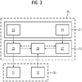
- Fig. 3 schematically illustrates a control apparatus 30 for controlling a machine 30 by executing program steps which verifiably execute predefined control tasks.
- the control apparatus 20 is configured to execute the method steps as described above.
- the control apparatus 20 is connected to or integrated into the machine 30 and controls the operation of machine 30.
- the control apparatus 20 transmits control commands to at least one actuator 31 of the machine.
- the actuator 31 performs actions according to the commands.
- the machine 30 comprises at least one sensor 32 which acquires values of parameters of the machine or related to the machine or from the environment of the machine.
- the control apparatus 20 comprises a control architecture 22 consisting of a data processing unit 27, a control processing unit 25 and a data storage unit 26.
- the control apparatus 20 further comprises an engineering architecture 21 comprising a graphical control programming interface 23 configured to input explicit guarantees according to the control program steps to the control processing unit 25.
- the engineering architecture 21 further comprises a data programming interface 24 configured to enter data rules according to the declarative program paradigm to the data processing unit 27.
- the data processing unit 27 is configured to manipulate data based on input data received from the machine 30, especially based on sensor data sampled by the sensor 32 resulting in reference data.
- the data processing unit 27 processes the input data by data program steps structured according to a declarative programming paradigm resulting.
- the data processing unit 27 is configured as an inference engine, which applies logical rules to a knowledge base including the input data provided by the data storage unit 26 to deduce new information.
- the control apparatus 20 comprises a control processing unit 27 configured to perform control program steps verifying the reference data with respect to explicit conditions, without any further manipulation of the reference data in the control processing unit 25 and providing instructions resulting from the performed control program steps to the machine for execution of instructions by the machine.
- the control processing unit 25 comprises a control program interpreter which proves the reference data depending on the control program steps.
- the control processing unit 25 especially verifies guarantees provided, e.g., by "guard" statements in the control program steps encoded according to a behavior tree, finite state machine or workflow diagram.
- Data processing unit 27 is connected to the control processing unit by the data storage unit 26 which is operating in a reactive way.
- the data storage unit 26 notifies both, data processing unit 27 and control processing unit 25 upon data changes, see dotted arrow.
- Data refers here to input data as well as reference data.
- Sensors 31 write only to the data storage unit 26. Only the control language interpreter of control processing unit 25 has access to the actuators 31. Relating to example shown in Fig. 5 , the data used in the definition of machineInSafeMode might change while the guarded part of the control code is executed. Therefore, the inference engine of the data processing unit 27 needs to react to input data changes. If input data, for instance coming from a sensor changes, the inference engine needs to redo all proofs involving this piece of data.
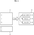
- Fig. 4 shows an embodiment of function split between data processing and control processing of a control task. It shows data program steps, see section 41, defining facts F1, .., Fm and rules R1, .., Rn according to the declarative programming paradigm. Facts are provided by the input data, e.g., sampled by sensors in the machine 11. Definitions of the facts, comprising definition of data types are shown in section 42. In the following examples data program steps R1, ..., Rn are shown according to the programming language Prolog:
- An exemplary related control program step is shown in section 43. It provides an explicit condition comprising a "Guard” decorator 44 monitoring the rule Rn defined by the data program step in section 41. Related to above rules the explicit condition is coded by "Guard (compatibleWorkpiece(currentWorkpiece))"
- control processing encoded by control program steps are explained in more details.
- the control program steps are encoded by behavior tree notation and shown in Fig. 5A to Fig. 5C .
- behavior tree programming is a mathematical model of plan execution used in computer science, robotics, control systems and video games. They describe switchings between a finite set of tasks in a modular fashion. Their strength comes from their ability to create very complex tasks composed of simple tasks, without worrying how the simple tasks are implemented. Behavior trees present some similarities to hierarchical state machines with the key difference that the main building block of a behavior is a task rather than a state. Its case of human understanding make behavior trees less error prone and very popular in the game developer community. Behavior trees have been shown to generalize several other control architectures.
- the behavior tree is graphically represented as a directed tree consisting of nodes, which are classified as root, control flow nodes, or execution nodes, also called tasks. For each pair of connected nodes, the outgoing node is called parent and the incoming node is called child.
- the root has no parents and exactly one child, the control flow nodes have one parent and at least one child, and the execution nodes have one parent and no children.
- the children of a control flow node are placed below it, ordered from left to right.
- the execution of the behavior tree starts from the root which sends ticks with a certain frequency to its child. A tick is an enabling signal that allows the execution of a child.
- the control flow node is used to control the subtasks of which it is composed.
- a control flow node may be either a "fallback” node or a "sequence” node. They run each of their subtasks in turn. When the subtask is completed and returns its status, i.e., success or failure, the control flow node decides whether to execute the next subtask or not.
- "Fallback” nodes are used to find and execute the first child that does not fail.
- a fallback node will return immediately with a status code of success or running when one of its children returns success or running. The children are ticked in order of importance, from left to right.
- "Sequence” nodes are used to find and execute the first child that has not yet succeeded. The sequence node will return immediately with a status code of failure or running when one of its children returns failure or. The children are ticked in order, from left to right.
- An explicit guarantee in a sub-task can be implemented by a "guard” statement which states an explicit condition with respect to the child node and subsequent subtree of the "guard” statement.
- the complete subtask is executed only if the explicit guarantee, here the "guard” node is proved to be "true”.
- the control processing unit 25 of the control apparatus 20, see Fig. 3 interprets the behavior tree 50 comprising behavior tree nodes 51-59 and instructs the machine 30 to execute the movements respectively.
- Nodes 51, 52, 54-57 are control flow node
- nodes 53, 58, 59 are execution nodes, i.e., tasks.
- Node 51 is a "fallback" composite, indicating that its subtree comprising nodes 52, 54-59 is executed as long as the child node 52 is proved to be true.
- the statement of node 52 is "While true”. If the child node 52 returns the value "false", task 53 is performed, e.g., the movement is stopped.
- This guard statement verifies the parameter "button_0" has the value "false”.
- the subtree built by node 55-59 controls the movement of the machine by node 55 indicating a "sequence" composite, indicated by a "triangle and arrow” symbol.
- the Sequence node is used to find and execute the first child, here node 56 or node 57 that has not yet succeeded.
- Fig. 5C shows the active node 51 and node 53 as hatched nodes.
- a machine is in SafeMode, if there is no open door which is a safety-door, and no lightbarrier that is interrupted.
- the data processing unit 22 configured to provide an inference engine needs to prove this in order to satisfy the guard statement.
- control engineering does not try to solve the problem of verifiability separately from control engineering but proposes a way of control engineering which makes guarantees explicitly visible and provable. This is achieved by firstly separating data processing and control, secondly making control code visual, and finally making data processing declarative and reactive.
Landscapes
- Engineering & Computer Science (AREA)
- General Physics & Mathematics (AREA)
- Physics & Mathematics (AREA)
- Automation & Control Theory (AREA)
- General Engineering & Computer Science (AREA)
- Quality & Reliability (AREA)
- Theoretical Computer Science (AREA)
- Robotics (AREA)
- Mechanical Engineering (AREA)
- Manufacturing & Machinery (AREA)
- Software Systems (AREA)
- Devices For Executing Special Programs (AREA)
- Stored Programmes (AREA)
Priority Applications (5)
| Application Number | Priority Date | Filing Date | Title |
|---|---|---|---|
| EP21175687.9A EP4095628A1 (de) | 2021-05-25 | 2021-05-25 | Verfahren und system zur steuerung einer maschine durch ausführen von programmschritten, die vordefinierte steuerungsaufgaben nachweisbar ausführen |
| CN202280037725.0A CN117396816A (zh) | 2021-05-25 | 2022-05-03 | 通过执行可验证地执行预定义的控制任务的程序步骤来控制机器的方法和系统 |
| EP22727102.0A EP4309009A1 (de) | 2021-05-25 | 2022-05-03 | Verfahren und system zur steuerung einer maschine durch ausführung von programmschritten, die verifizierbar vordefinierte steuerungsaufgaben ausführen |
| PCT/EP2022/061810 WO2022248170A1 (en) | 2021-05-25 | 2022-05-03 | Method and system for controlling a machine by executing program steps which verifiably execute predefined control tasks |
| US18/560,960 US20240231330A1 (en) | 2021-05-25 | 2022-05-03 | Method and system for controlling a machine by executing program steps which verifiably execute predefined control tasks |
Applications Claiming Priority (1)
| Application Number | Priority Date | Filing Date | Title |
|---|---|---|---|
| EP21175687.9A EP4095628A1 (de) | 2021-05-25 | 2021-05-25 | Verfahren und system zur steuerung einer maschine durch ausführen von programmschritten, die vordefinierte steuerungsaufgaben nachweisbar ausführen |
Publications (1)
| Publication Number | Publication Date |
|---|---|
| EP4095628A1 true EP4095628A1 (de) | 2022-11-30 |
Family
ID=76098861
Family Applications (2)
| Application Number | Title | Priority Date | Filing Date |
|---|---|---|---|
| EP21175687.9A Withdrawn EP4095628A1 (de) | 2021-05-25 | 2021-05-25 | Verfahren und system zur steuerung einer maschine durch ausführen von programmschritten, die vordefinierte steuerungsaufgaben nachweisbar ausführen |
| EP22727102.0A Pending EP4309009A1 (de) | 2021-05-25 | 2022-05-03 | Verfahren und system zur steuerung einer maschine durch ausführung von programmschritten, die verifizierbar vordefinierte steuerungsaufgaben ausführen |
Family Applications After (1)
| Application Number | Title | Priority Date | Filing Date |
|---|---|---|---|
| EP22727102.0A Pending EP4309009A1 (de) | 2021-05-25 | 2022-05-03 | Verfahren und system zur steuerung einer maschine durch ausführung von programmschritten, die verifizierbar vordefinierte steuerungsaufgaben ausführen |
Country Status (4)
| Country | Link |
|---|---|
| US (1) | US20240231330A1 (de) |
| EP (2) | EP4095628A1 (de) |
| CN (1) | CN117396816A (de) |
| WO (1) | WO2022248170A1 (de) |
Family Cites Families (2)
| Publication number | Priority date | Publication date | Assignee | Title |
|---|---|---|---|---|
| JP2006344136A (ja) * | 2005-06-10 | 2006-12-21 | Fanuc Ltd | ロボット制御装置 |
| CN112235419B (zh) * | 2020-12-09 | 2021-03-09 | 之江实验室 | 基于行为树的机器人云平台执行引擎和执行方法 |
-
2021
- 2021-05-25 EP EP21175687.9A patent/EP4095628A1/de not_active Withdrawn
-
2022
- 2022-05-03 US US18/560,960 patent/US20240231330A1/en active Pending
- 2022-05-03 EP EP22727102.0A patent/EP4309009A1/de active Pending
- 2022-05-03 CN CN202280037725.0A patent/CN117396816A/zh active Pending
- 2022-05-03 WO PCT/EP2022/061810 patent/WO2022248170A1/en not_active Ceased
Non-Patent Citations (2)
| Title |
|---|
| FICHERA LORIS ET AL: "A Python framework for programming autonomous robots using a declarative approach", SCIENCE OF COMPUTER PROGRAMMING, vol. 139, 1 June 2017 (2017-06-01), pages 36 - 55, XP029937747, ISSN: 0167-6423, DOI: 10.1016/J.SCICO.2017.01.003 * |
| FRENCH KEVIN ET AL: "Learning Behavior Trees From Demonstration", 2019 INTERNATIONAL CONFERENCE ON ROBOTICS AND AUTOMATION (ICRA), IEEE, 20 May 2019 (2019-05-20), pages 7791 - 7797, XP033594088, DOI: 10.1109/ICRA.2019.8794104 * |
Also Published As
| Publication number | Publication date |
|---|---|
| EP4309009A1 (de) | 2024-01-24 |
| WO2022248170A1 (en) | 2022-12-01 |
| CN117396816A (zh) | 2024-01-12 |
| US20240231330A1 (en) | 2024-07-11 |
Similar Documents
| Publication | Publication Date | Title |
|---|---|---|
| Lewis | Modelling control systems using IEC 61499: Applying function blocks to distributed systems | |
| Gabor et al. | A simulation-based architecture for smart cyber-physical systems | |
| Fleury et al. | G/sup en/om: a tool for the specification and the implementation of operating modules in a distributed robot architecture | |
| Mayr et al. | Skiros2: A skill-based robot control platform for ros | |
| US20220350308A1 (en) | Method for automatically generating a behavior tree program for controlling a machine | |
| Dahl et al. | Interactive formal specification for efficient preparation of intelligent automation systems | |
| Sorouri et al. | Software composition and distributed operation scheduling in modular automated machines | |
| Huang et al. | Compositional coordination for multi-robot teams with large language models | |
| EP4095628A1 (de) | Verfahren und system zur steuerung einer maschine durch ausführen von programmschritten, die vordefinierte steuerungsaufgaben nachweisbar ausführen | |
| Wilch et al. | Enhancing the resilience of iec 61131-3 software with online reconfigurations for fault handling | |
| Alenljung et al. | Sensor graphs for discrete event modeling applied to formal verification of PLCs | |
| Ivanova et al. | Combining IEC 61499 and ISA S88 for batch control | |
| Alloui et al. | A multi-agent approach for modelling, enacting and evolving distributed cooperative software processes | |
| Kim et al. | A supervisory control approach for execution control of an FMC | |
| Bauer et al. | Towards automatic verification of embedded control software | |
| Meywerk et al. | Verifying safety properties of robotic plans operating in real-world environments via logic-based environment modeling | |
| Curto Diego et al. | Applying a software framework for supervisory control of a PLC-based flexible manufacturing systems | |
| Legat et al. | Automatic generation of field control strategies for supporting (re-) engineering of manufacturing systems | |
| Renard et al. | Novel Supervisor-Based Architecture for Logic Controller Design | |
| US12420408B1 (en) | Human machine interface recipe building system for a robotic manufacturing system | |
| Hune et al. | A case study on using automata in control synthesis | |
| Pomponio et al. | Reusability and Modifiability in Robotics Software (Extended Version) | |
| Wardana | Development of automatic program verification for continuous function chart based on model checking | |
| Wonham et al. | Supervision of discrete-event systems: Basics | |
| Ivanushkin et al. | To the synthesis of the initial algorithms for control and diagnostic control of discrete automata based on programmable logic controllers |
Legal Events
| Date | Code | Title | Description |
|---|---|---|---|
| PUAI | Public reference made under article 153(3) epc to a published international application that has entered the european phase |
Free format text: ORIGINAL CODE: 0009012 |
|
| STAA | Information on the status of an ep patent application or granted ep patent |
Free format text: STATUS: THE APPLICATION HAS BEEN PUBLISHED |
|
| AK | Designated contracting states |
Kind code of ref document: A1 Designated state(s): AL AT BE BG CH CY CZ DE DK EE ES FI FR GB GR HR HU IE IS IT LI LT LU LV MC MK MT NL NO PL PT RO RS SE SI SK SM TR |
|
| STAA | Information on the status of an ep patent application or granted ep patent |
Free format text: STATUS: THE APPLICATION IS DEEMED TO BE WITHDRAWN |
|
| 18D | Application deemed to be withdrawn |
Effective date: 20230531 |