EP4095589A1 - Display device - Google Patents
Display device Download PDFInfo
- Publication number
- EP4095589A1 EP4095589A1 EP22173833.9A EP22173833A EP4095589A1 EP 4095589 A1 EP4095589 A1 EP 4095589A1 EP 22173833 A EP22173833 A EP 22173833A EP 4095589 A1 EP4095589 A1 EP 4095589A1
- Authority
- EP
- European Patent Office
- Prior art keywords
- light
- light guide
- guide layer
- optical structure
- layer
- Prior art date
- Legal status (The legal status is an assumption and is not a legal conclusion. Google has not performed a legal analysis and makes no representation as to the accuracy of the status listed.)
- Granted
Links
Images



Classifications
-
- G—PHYSICS
- G02—OPTICS
- G02B—OPTICAL ELEMENTS, SYSTEMS OR APPARATUS
- G02B30/00—Optical systems or apparatus for producing three-dimensional [3D] effects, e.g. stereoscopic images
- G02B30/50—Optical systems or apparatus for producing three-dimensional [3D] effects, e.g. stereoscopic images the image being built up from image elements distributed over a three-dimensional [3D] volume, e.g. voxels
- G02B30/56—Optical systems or apparatus for producing three-dimensional [3D] effects, e.g. stereoscopic images the image being built up from image elements distributed over a three-dimensional [3D] volume, e.g. voxels by projecting aerial or floating images
-
- G—PHYSICS
- G02—OPTICS
- G02B—OPTICAL ELEMENTS, SYSTEMS OR APPARATUS
- G02B27/00—Optical systems or apparatus not provided for by any of the groups G02B1/00 - G02B26/00, G02B30/00
- G02B27/0093—Optical systems or apparatus not provided for by any of the groups G02B1/00 - G02B26/00, G02B30/00 with means for monitoring data relating to the user, e.g. head-tracking, eye-tracking
-
- G—PHYSICS
- G02—OPTICS
- G02B—OPTICAL ELEMENTS, SYSTEMS OR APPARATUS
- G02B27/00—Optical systems or apparatus not provided for by any of the groups G02B1/00 - G02B26/00, G02B30/00
- G02B27/28—Optical systems or apparatus not provided for by any of the groups G02B1/00 - G02B26/00, G02B30/00 for polarising
- G02B27/283—Optical systems or apparatus not provided for by any of the groups G02B1/00 - G02B26/00, G02B30/00 for polarising used for beam splitting or combining
-
- G—PHYSICS
- G02—OPTICS
- G02B—OPTICAL ELEMENTS, SYSTEMS OR APPARATUS
- G02B30/00—Optical systems or apparatus for producing three-dimensional [3D] effects, e.g. stereoscopic images
- G02B30/40—Optical systems or apparatus for producing three-dimensional [3D] effects, e.g. stereoscopic images giving the observer of a single two-dimensional [2D] image a perception of depth
-
- G—PHYSICS
- G02—OPTICS
- G02B—OPTICAL ELEMENTS, SYSTEMS OR APPARATUS
- G02B30/00—Optical systems or apparatus for producing three-dimensional [3D] effects, e.g. stereoscopic images
- G02B30/60—Optical systems or apparatus for producing three-dimensional [3D] effects, e.g. stereoscopic images involving reflecting prisms and mirrors only
-
- G—PHYSICS
- G02—OPTICS
- G02B—OPTICAL ELEMENTS, SYSTEMS OR APPARATUS
- G02B5/00—Optical elements other than lenses
- G02B5/02—Diffusing elements; Afocal elements
- G02B5/0205—Diffusing elements; Afocal elements characterised by the diffusing properties
- G02B5/0252—Diffusing elements; Afocal elements characterised by the diffusing properties using holographic or diffractive means
-
- H—ELECTRICITY
- H04—ELECTRIC COMMUNICATION TECHNIQUE
- H04N—PICTORIAL COMMUNICATION, e.g. TELEVISION
- H04N13/00—Stereoscopic video systems; Multi-view video systems; Details thereof
- H04N13/30—Image reproducers
- H04N13/388—Volumetric displays, i.e. systems where the image is built up from picture elements distributed through a volume
Definitions
- the present invention relates to a display device that displays an image in air using retroreflection.
- JP 2013-517528 A discloses a stereoscopic display that enables stereoscopic vision by imparting a lens structure or a prism structure as a configuration for obtaining stereoscopic effect on a display. Further, aerial imaging by retro-reflection (AIRR) using retroreflection is known. For example, in order to enable observation of an image formed in the air from a wider angle, the display device of JP 2017-107165 A uses two retroreflective members, and one of the retroreflective members is arranged on the emission axis of the light source.
- a half mirror, a retroreflective member, and an image output device are disposed in parallel and a position of the half mirror or the image output device is changed so that the image forming position can be adjusted.
- the image display device of JP 2019-66833 A in order to minimize a decrease in visibility of an image, the number of times of light transmission through a phase difference member ( ⁇ /4 plate) is reduced and it is made difficult for dust or the like to enter between a retroreflective member and the phase difference member.
- a display and a retroreflective member are disposed parallel to a beam splitter and a deflection optical element is disposed on the display.
- Fig. 1A illustrates an example in which a display device that displays an aerial image is applied to a spatial input device.
- the spatial input device 10 includes a housing (structure) 20 that accommodates a display device that generates an aerial image, and a three-dimensional distance sensor 50 that detects approach of an object (for example, a user's finger or the like) 40 to the aerial image 30 generated above the housing 20.
- the aerial image 30 includes, for example, left and right scroll keys 60 and 62 and icon images 70 to 80 for instructing input as illustrated in Fig. 1B .
- An object of the present invention is to provide a display device capable of displaying an aerial image that is easily visually recognized, and a spatial input device using the display device.
- the invention relates to a display device according to the appended claims. Embodiments are disclosed in the dependent claims.
- a display device is capable of displaying an aerial image using retroreflection, the display device including a first optical structure that forms a multiple image by light diffused or scattered by a first light diffusion surface of a first light guide layer, and a second optical structure that retroreflects light diffused or scattered by a second light diffusion surface of a second light guide layer to form an aerial image, in which the first optical structure and the second optical structure are in a stacked relationship, and the first light diffusion surface and the second light diffusion surface are disposed at positions not overlapping each other.
- the first optical structure includes reflection members formed on an upper surface side and a bottom surface side of the first light guide layer, and light incident from a side portion of the first light guide layer is diffused or scattered by the first light diffusion surface formed on a bottom surface or a bottom portion of the first light guide layer.
- the second optical structure includes a retroreflective layer formed on a bottom surface side of the second light guide layer, and light incident from a side portion of the second light guide layer is diffused or scattered by the second light diffusion surface formed on a bottom surface or a bottom portion of the second light guide layer.
- the second optical structure is stacked on the first optical structure
- the first optical structure includes a reflection layer, a first light guide layer formed on the reflection layer, and a beam splitter formed on the first light guide layer
- the second optical structure includes a retroreflective layer, a second light guide layer formed on the retroreflective layer, and a beam splitter formed on the second light guide layer, and a multiple image formed by the first light diffusion surface of the first light guide layer and an aerial image formed by the second light diffusion surface of the second light guide layer can be simultaneously observed from above the second optical structure.
- the first optical structure is stacked on the second optical structure
- the second optical structure includes a retroreflective layer and a second light guide layer formed on the retroreflective layer
- the first optical structure includes a reflection layer, a first light guide layer formed on the reflection layer, and a beam splitter formed on the first light guide layer, and a multiple image formed by the first light diffusion surface of the first light guide layer and an aerial image formed by the second light diffusion surface of the second light guide layer can be simultaneously observed from above the first optical structure.
- a color of light incident on the first light guide layer is different from a color of light incident on the second light guide layer.
- the second optical structure further includes a ⁇ /4 plate between a second light guide layer and the retroreflective layer, and a beam splitter formed on an upper surface of the second light guide layer is a polarization beam splitter.
- a spatial input device includes a display device as described herein, and a detection unit that detects an approach of an object to an aerial video displayed by the display device.
- the aerial image and the multiple image are simultaneously formed, a sense of depth or a stereoscopic effect is imparted to the aerial image by the multiple image, and the aerial image is made conspicuous, by which visual attraction of the aerial image is enhanced, and the aerial image is easily recognized.
- a display device of embodiments of the present invention displays a video using retroreflection in a three-dimensional space without wearing special glasses or the like.
- the display device of the present invention is applied to a user input interface using a video displayed in the air.
- the drawings referred to in the following description of embodiments include exaggerated display in order to facilitate understanding of the invention, and do not directly represent the shape and scale of an actual product.
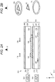
- Fig. 2A is a schematic cross-sectional view of a display device that displays an aerial image according to the first embodiment of the present invention
- Fig. 2B is a perspective view schematically illustrating designs of light diffusion surfaces formed in light guide layers.
- two light guide layers are stacked, an aerial image is formed by a light diffusion surface of one of the light guide layers, and a multiple image with a sense of depth is formed around or outside the aerial image by a light diffusion surface of the other light guide layer, thereby making the aerial image conspicuous, enhancing visual attraction, and facilitating visual recognition of the aerial image.
- the display device 100 includes a first optical structure 200 and a second optical structure 300 disposed above the first optical structure 200.
- the first optical structure 200 includes a light source 210, a light guide layer 220, a reflection layer 230 disposed below the light guide layer 220, and a half mirror 240 disposed above the light guide layer 220.
- the light source 210 emits light L1 having a constant emission angle (or radiation angle) in the X direction.
- the emitted light L1 enters the inside from a side portion 222 of the transparent light guide layer 220, and uniformly irradiates the inside of the light guide layer 220.
- the light source 210 is not particularly limited, but for example, a light emitting diode, a laser diode, or the like is used.
- the color (wavelength) of the light L1 emitted from the light source 210 is not particularly limited, but may be the same as or different from the color of the light L2 emitted from the second light source 310, for example.
- a plurality of the light sources 210 may be arranged along the Y direction of the side portion 222 of the light guide layer 220. Furthermore, although the light L1 is incident from one side portion of the light guide layer 220, the light may be incident from both side portions.
- the light guide layer 220 is a transparent plate-like or film-like optical member including a flat upper surface, a flat lower surface, and side surfaces connecting the upper surface and the lower surface.
- the light guide layer 220 a known one can be used, and is made of, for example, glass, acrylic plastic, polycarbonate resin, cycloolefin-based resin, or the like.
- the light guide layer 220 has a constant thickness in the Z direction in order to allow the light L1 from the light source 210 to enter from the side portion 222.
- a light diffusion surface 226 for diffusion the incident light L1 in the Z direction is formed on a bottom portion or a bottom surface 224 of the light guide layer 220.
- the light diffusion surface 226 is formed, for example, by performing laser processing or printing processing on the bottom surface 224 of the light guide layer 220.
- the light diffusion surface 226 generates a design (original image) for forming a multiple image around or outside the aerial image, and the design is arbitrarily determined in relation to the aerial image.
- the light diffusion surface 226 is processed to produce a ring-shaped or annular design P1.
- the reflection layer 230 is disposed so as to be in contact with the bottom surface 224 of the light guide layer 220.
- the reflection layer 230 is, for example, a plate-shaped, film-shaped, or thin-film-shaped member having the same shape as the bottom surface 224 of the light guide layer 220, and the material thereof is not particularly limited.
- the reflection layer 230 totally reflects the light L1 incident on the light guide layer 220.
- the half mirror 240 is disposed so as to be in contact with the upper surface of the light guide layer 220.
- the half mirror 240 is, for example, a transparent optical member having the same shape as the upper surface of the light guide layer 220 and separating incident light into reflected light and transmitted light.
- the half mirror 240 is configured by, for example, forming a dielectric multilayer film, an anti-reflection film, or the like on a front surface or a back surface of a substrate such as flat glass or plastic.
- the half mirror 240 in which an amount of reflected light and an amount of transmitted light are equal to each other is exemplified, but a beam splitter in which a ratio between the amount of reflected light and the amount of transmitted light is different in accordance with the luminance of the light source 210 or the luminance of the aerial image may be used.
- the light L1 incident from the side portion 222 of the light guide layer 220 travels in the X direction, is diffused or scattered in the Z direction by the light diffusion surface 226, and the light diffused or scattered by the light diffusion surface 226 repeats multiple reflection between the reflection layer 230 and the half mirror 240.
- a multiple virtual image of the design P1 is generated on the back surface of the first optical structure 200 due to the effect of facing mirrors.
- the second optical structure 300 includes a light source 310, a light guide layer 320, a retroreflective layer 330 disposed below the light guide layer 320, and a half mirror 340 disposed above the light guide layer 320.
- the light source 310 emits light L2 having a constant emission angle (or radiation angle) in the X direction.
- the emitted light L2 enters the inside from the side portion 322 of the transparent light guide layer 320, and uniformly irradiates the inside of the light guide layer 320.
- the light source 310 includes, similarly to the light source 210, one or a plurality of light emitting diodes or laser diodes, for example. Note that in a case where the light L2 of the light source 310 and the light L1 of the light source 210 have the same color, light emitted from a single light source may be divided into two by a beam splitter or the like, and the divided light may be emitted to the light guide layers 220 and 320, respectively.
- the light guide layer 320 is a transparent plate-like or film-like optical member including a flat upper surface, a flat lower surface, and side surfaces connecting the upper surface and the lower surface, and is formed of a member similar to the light guide layer 220.
- the light guide layer 320 has a constant thickness in the Z direction in order to allow the light L2 of the light source 310 to enter from the side portion 322.
- a light diffusion surface 326 for diffusing the incident light in the Z direction is formed on the bottom portion or a bottom surface 324 of the light guide layer 320.
- the light diffusion surface 326 is formed, for example, by performing laser processing or printing processing on the bottom surface 324 of the light guide layer 320.
- the light diffusion surface 326 generates a design (original image) for forming an aerial image, and the design is arbitrarily determined.
- the light diffusion surface 326 is located inside or on an inner periphery of the light diffusion surface 226, and is processed so as to generate a triangular design P2 in which an opening is formed at the center.
- the retroreflective layer 330 is formed so as to be in contact with the bottom surface of the light guide layer 320.
- the retroreflective layer 330 is an optical member that reflects light in the same direction as the incident light, and is not particularly limited in its configuration but includes, for example, prismatic retroreflective elements such as triangular pyramid retroreflective elements and full cube corner retroreflective elements, or bead retroreflective elements.
- the retroreflective layer 330 is disposed at a position not interfering with the light diffusion surface 226, that is, at a position inside the light diffusion surface 226, and is disposed so as to substantially overlap the light diffusion surface 326 (here, since the design P2 has an opening at the center, the opening is shielded).
- the half mirror 340 is disposed so as to be in contact with the upper surface of the light guide layer 320.
- the half mirror 340 has, for example, the same shape as the upper surface of the light guide layer 320, and is configured similarly to the half mirror 240.
- the half mirror 340 in which the amount of reflected light and the amount of transmitted light are equal to each other is exemplified, but a beam splitter in which a ratio between the amount of reflected light and the amount of transmitted light is different in accordance with the luminance of the light source 310 or the luminance of the aerial image may be used.
- the light L2 incident from the side portion 322 of the light guide layer 320 travels in the X direction and is diffused or scattered in the X direction by the light diffusion surface 326, a part of the diffused or scattered light is reflected by the half mirror 340, and the reflected light is incident on the retroreflective layer 330.
- the light incident on the retroreflective layer 330 is reflected in the same direction as the incident light, and a part thereof is transmitted through the half mirror 340 and forms an image again.
- An aerial image 400 of the design P2 floating up from the second optical structure 300 is observed from the viewpoint U of the user in the Z direction. Further, simultaneously with the aerial image 400, a multiple image 410 of the design P1 generated on the outer periphery of the aerial image 400 is also observed.
- Fig. 3 is a perspective view schematically illustrating a relationship between the multiple image 410 of the design P1 and the aerial image 400 of the design P2.
- the first optical structure 200 generates multiple reflection of the design P1 due to the effect of facing mirrors and produces the multiple virtual image 410 having a depth feeling equal to or greater than the thickness of a real object.
- the second optical structure 300 forms the aerial image 400 of the design P2 inside or around the multiple virtual image 410.
- the stereoscopic effect of the aerial image 400 is emphasized, the visual attraction is increased, and the probability of being recognized as the aerial display even at the first sight can be increased.
- the aerial image 400 can be made more conspicuous by making the color of the light source 210 different from the color of the light source 310.
- the second optical structure for generating the aerial image is not limited to the configuration of Figs. 2A and 2B , and may have a configuration as illustrated in Fig. 4 , for example.
- the polarization beam splitter 350 is disposed on the upper portion of the light guide plate 320 instead of the half mirror 340, and the ⁇ /4 plate 360 is disposed between the light guide layer 320 and the retroreflective layer 330.
- the polarization beam splitter 350 is a polarization separation element capable of dividing incident light into a p-polarization component and an s-polarization component, and can transmit a light component linearly polarized in a certain specific direction. If the light L2 incident from the light source 310 is unpolarized light including various polarization components, a part of the light reflected by the light diffusion surface 326 is transmitted through the polarization beam splitter 350, and the other light is reflected by the polarization beam splitter 350.
- the direction of the linearly polarized light transmitted by the polarization beam splitter 350 is set to be different from the direction of the linearly polarized light of the incident light L2, and most of the light L2 is reflected by the polarization beam splitter 350.
- the ⁇ /4 plate 360 gives a phase difference ⁇ /2 (90 degrees) to the light incident from the light guide layer 320 and transmits the light. For example, when linearly polarized light is incident, it is converted into circularly polarized light (or elliptically polarized light), and when circularly polarized light (or elliptically polarized light) is incident, it is converted into linearly polarized light.
- the retroreflective layer 330 reflects the light transmitted through the ⁇ /4 plate 360 in the same direction as the incident light.
- a phase difference ⁇ /2 is given.
- the light transmitted through the ⁇ /4 plate 360 has a phase difference ⁇ from the light incident on the ⁇ /4 plate 360.
- the light incident on the ⁇ /4 plate 360 is linearly polarized light
- the light becomes circularly polarized light (or elliptically polarized light) when it is transmitted through the ⁇ /4 plate 360
- this circularly polarized light is retroreflected an odd number of times by the retroreflective layer 330
- the circularly polarized light becomes circularly polarized light in the opposite direction
- this circularly polarized light in the opposite direction is transmitted through the ⁇ /4 plate 360, it becomes linearly polarized light in a direction 180 degrees different from the original linearly polarized light.
- the light transmitted through the ⁇ /4 plate 360 is incident on the polarization beam splitter 350
- most of the reflected light is transmitted through the polarization beam splitter 350
- the transmitted light forms an image, and an aerial image is formed.
- a display device 100A according to a second embodiment of the present invention is illustrated in Figs. 5A and 5B .
- the stacking direction is reversed from that of the first embodiment, and the first optical structure 200 is stacked above the second optical structure 300.
- the light diffusion surface 326 is formed on the bottom surface 324 of the light guide layer 320 of the second optical structure 300.
- the light diffusion surface 326 is processed to form the triangular design P2.
- the retroreflective layer 330 is disposed on the bottom surface of the light guide layer 320 so as to generate the aerial image 400 of the design P2.
- the light diffusion surface 226 is formed on the outer peripheral portion of the bottom surface 224 of the light guide layer 220 of the first optical structure 200.
- the light diffusion surface 226 is processed to form the ring-shaped design P1.
- the design P1 is formed at a position not overlapping with the design P2.
- a ring-shaped reflection layer 230 is formed below the light diffusion surface 226.
- the opening 232 at the center of the reflection layer 230 has a size that exposes the light diffusion surface 326 and the retroreflective layer 330 so that the aerial image 400 is not shielded.
- a part of the light diffused or scattered in the Z direction by the light diffusion surface 326 is reflected by the half mirror 240 of the first optical structure 200 via the opening 232, the reflected light is incident on the retroreflective layer 330, this incident light is reflected by the retroreflective layer 330 in the same direction, and a part of this reflected light is transmitted through the half mirror 240 to generate the aerial image 400.
- the multiple virtual image 410 of the design P1 generated by the first optical structure 200 is projected around the aerial image 400 of the design P2 generated by the second optical structure 300, the sense of depth is imparted to the aerial image 400, and recognition of the aerial image becomes easy. Further, in the present embodiment, by arranging the second optical structure 300 below the first optical structure 200, a distance D at which the aerial image 400 floats up can be made larger than that in the first embodiment, and an aerial image with a more stereoscopic effect can be displayed.
- the spatial input device includes a sensor that causes the display devices 100 and 100A of the present embodiment to display the aerial image 400 and detects an approach of an object (for example, a user's finger or the like) to the aerial image 400.
- the configuration of the sensor is not particularly limited, but for example, the sensor detects the approach of an object by a three-dimensional distance sensor, or detects the proximity of an object by analyzing image data captured by an imaging camera.
- the spatial input device of the present embodiment can be applied to any user input, and can be applied to, for example, a computer device, an in-vehicle electronic device, an ATM of a bank or the like, a ticket purchasing machine of a station or the like, an input button of an elevator, and the like.
Landscapes
- Physics & Mathematics (AREA)
- General Physics & Mathematics (AREA)
- Optics & Photonics (AREA)
- Engineering & Computer Science (AREA)
- Multimedia (AREA)
- Signal Processing (AREA)
- Position Input By Displaying (AREA)
- Illuminated Signs And Luminous Advertising (AREA)
Abstract
Description
- The present invention relates to a display device that displays an image in air using retroreflection.
-
JP 2013-517528 A JP 2017-107165 A JP 2018-81138 A JP 2019-66833 A JP 2019-101055 A -
Fig. 1A illustrates an example in which a display device that displays an aerial image is applied to a spatial input device. Thespatial input device 10 includes a housing (structure) 20 that accommodates a display device that generates an aerial image, and a three-dimensional distance sensor 50 that detects approach of an object (for example, a user's finger or the like) 40 to theaerial image 30 generated above thehousing 20. Theaerial image 30 includes, for example, left andright scroll keys icon images 70 to 80 for instructing input as illustrated inFig. 1B . - In a case where only the
aerial image 30 is displayed, a situation often occurs in which, when the user sees theaerial image 30, the user recognizes that theaerial image 30 is displayed on thestructure 20 on a back surface, and does not recognize it as theaerial image 30 in the first place. This is related to a human cognitive process, and is caused by superimposing theaerial image 30 on a background object in the brain when viewing the aerial image. When theaerial image 30 is used as a non-contact device, it is necessary to make the user visually recognize the fact, and how to make the aerial image stand out and easily recognized is a problem in implementation. - An object of the present invention is to provide a display device capable of displaying an aerial image that is easily visually recognized, and a spatial input device using the display device.
- The invention relates to a display device according to the appended claims. Embodiments are disclosed in the dependent claims.
- A display device according to an aspect of the present invention is capable of displaying an aerial image using retroreflection, the display device including a first optical structure that forms a multiple image by light diffused or scattered by a first light diffusion surface of a first light guide layer, and a second optical structure that retroreflects light diffused or scattered by a second light diffusion surface of a second light guide layer to form an aerial image, in which the first optical structure and the second optical structure are in a stacked relationship, and the first light diffusion surface and the second light diffusion surface are disposed at positions not overlapping each other.
- In one embodiment, the first optical structure includes reflection members formed on an upper surface side and a bottom surface side of the first light guide layer, and light incident from a side portion of the first light guide layer is diffused or scattered by the first light diffusion surface formed on a bottom surface or a bottom portion of the first light guide layer. In one embodiment, the second optical structure includes a retroreflective layer formed on a bottom surface side of the second light guide layer, and light incident from a side portion of the second light guide layer is diffused or scattered by the second light diffusion surface formed on a bottom surface or a bottom portion of the second light guide layer. In one embodiment, the second optical structure is stacked on the first optical structure, the first optical structure includes a reflection layer, a first light guide layer formed on the reflection layer, and a beam splitter formed on the first light guide layer, and the second optical structure includes a retroreflective layer, a second light guide layer formed on the retroreflective layer, and a beam splitter formed on the second light guide layer, and a multiple image formed by the first light diffusion surface of the first light guide layer and an aerial image formed by the second light diffusion surface of the second light guide layer can be simultaneously observed from above the second optical structure. In one embodiment, the first optical structure is stacked on the second optical structure, the second optical structure includes a retroreflective layer and a second light guide layer formed on the retroreflective layer, and the first optical structure includes a reflection layer, a first light guide layer formed on the reflection layer, and a beam splitter formed on the first light guide layer, and a multiple image formed by the first light diffusion surface of the first light guide layer and an aerial image formed by the second light diffusion surface of the second light guide layer can be simultaneously observed from above the first optical structure. In one embodiment, a color of light incident on the first light guide layer is different from a color of light incident on the second light guide layer. In one embodiment, the second optical structure further includes a λ/4 plate between a second light guide layer and the retroreflective layer, and a beam splitter formed on an upper surface of the second light guide layer is a polarization beam splitter.
- A spatial input device according to another aspect of the present invention includes a display device as described herein, and a detection unit that detects an approach of an object to an aerial video displayed by the display device.
- According to aspects of the present invention, since the aerial image and the multiple image are simultaneously formed, a sense of depth or a stereoscopic effect is imparted to the aerial image by the multiple image, and the aerial image is made conspicuous, by which visual attraction of the aerial image is enhanced, and the aerial image is easily recognized.
-
Figs. 1A and 1B are views illustrating a configuration example in which a conventional display device that displays an aerial image is applied to a spatial input device. -
Fig. 2A is a schematic cross-sectional view of a display device according to a first embodiment of the present invention, andFig. 2B is a perspective view schematically illustrating designs generated by light diffusion surfaces. -
Fig. 3 is a diagram illustrating an effect of the display device according to the first embodiment of the present invention. -
Fig. 4 is a schematic cross-sectional view illustrating a modification example of a second optical device according to the first embodiment of the present invention. -
Fig. 5A is a schematic cross-sectional view of a display device according to a second embodiment of the present invention, andFig. 5B is a perspective view schematically illustrating designs generated by light diffusion surfaces. - Embodiments of the present invention will be described below. A display device of embodiments of the present invention displays a video using retroreflection in a three-dimensional space without wearing special glasses or the like. In an embodiment, the display device of the present invention is applied to a user input interface using a video displayed in the air. It should be noted that the drawings referred to in the following description of embodiments include exaggerated display in order to facilitate understanding of the invention, and do not directly represent the shape and scale of an actual product.
- An embodiment of the present invention will be described in detail below.
Fig. 2A is a schematic cross-sectional view of a display device that displays an aerial image according to the first embodiment of the present invention, andFig. 2B is a perspective view schematically illustrating designs of light diffusion surfaces formed in light guide layers. - In the display device of the present embodiment, two light guide layers are stacked, an aerial image is formed by a light diffusion surface of one of the light guide layers, and a multiple image with a sense of depth is formed around or outside the aerial image by a light diffusion surface of the other light guide layer, thereby making the aerial image conspicuous, enhancing visual attraction, and facilitating visual recognition of the aerial image.
- As illustrated in the drawing, the
display device 100 includes a firstoptical structure 200 and a secondoptical structure 300 disposed above the firstoptical structure 200. The firstoptical structure 200 includes alight source 210, alight guide layer 220, areflection layer 230 disposed below thelight guide layer 220, and ahalf mirror 240 disposed above thelight guide layer 220. - The
light source 210 emits light L1 having a constant emission angle (or radiation angle) in the X direction. The emitted light L1 enters the inside from aside portion 222 of the transparentlight guide layer 220, and uniformly irradiates the inside of thelight guide layer 220. Thelight source 210 is not particularly limited, but for example, a light emitting diode, a laser diode, or the like is used. The color (wavelength) of the light L1 emitted from thelight source 210 is not particularly limited, but may be the same as or different from the color of the light L2 emitted from thesecond light source 310, for example. Further, in a case where theside portion 222 of thelight guide layer 220 has a certain length in the Y direction, a plurality of thelight sources 210 may be arranged along the Y direction of theside portion 222 of thelight guide layer 220. Furthermore, although the light L1 is incident from one side portion of thelight guide layer 220, the light may be incident from both side portions. - The
light guide layer 220 is a transparent plate-like or film-like optical member including a flat upper surface, a flat lower surface, and side surfaces connecting the upper surface and the lower surface. As thelight guide layer 220, a known one can be used, and is made of, for example, glass, acrylic plastic, polycarbonate resin, cycloolefin-based resin, or the like. Thelight guide layer 220 has a constant thickness in the Z direction in order to allow the light L1 from thelight source 210 to enter from theside portion 222. - A
light diffusion surface 226 for diffusion the incident light L1 in the Z direction is formed on a bottom portion or abottom surface 224 of thelight guide layer 220. Thelight diffusion surface 226 is formed, for example, by performing laser processing or printing processing on thebottom surface 224 of thelight guide layer 220. Thelight diffusion surface 226 generates a design (original image) for forming a multiple image around or outside the aerial image, and the design is arbitrarily determined in relation to the aerial image. In the example of the drawings, thelight diffusion surface 226 is processed to produce a ring-shaped or annular design P1. - The
reflection layer 230 is disposed so as to be in contact with thebottom surface 224 of thelight guide layer 220. Thereflection layer 230 is, for example, a plate-shaped, film-shaped, or thin-film-shaped member having the same shape as thebottom surface 224 of thelight guide layer 220, and the material thereof is not particularly limited. Thereflection layer 230 totally reflects the light L1 incident on thelight guide layer 220. - The
half mirror 240 is disposed so as to be in contact with the upper surface of thelight guide layer 220. Thehalf mirror 240 is, for example, a transparent optical member having the same shape as the upper surface of thelight guide layer 220 and separating incident light into reflected light and transmitted light. Thehalf mirror 240 is configured by, for example, forming a dielectric multilayer film, an anti-reflection film, or the like on a front surface or a back surface of a substrate such as flat glass or plastic. Here, thehalf mirror 240 in which an amount of reflected light and an amount of transmitted light are equal to each other is exemplified, but a beam splitter in which a ratio between the amount of reflected light and the amount of transmitted light is different in accordance with the luminance of thelight source 210 or the luminance of the aerial image may be used. - The light L1 incident from the
side portion 222 of thelight guide layer 220 travels in the X direction, is diffused or scattered in the Z direction by thelight diffusion surface 226, and the light diffused or scattered by thelight diffusion surface 226 repeats multiple reflection between thereflection layer 230 and thehalf mirror 240. When the user observes from a viewpoint U in the Z direction, a multiple virtual image of the design P1 is generated on the back surface of the firstoptical structure 200 due to the effect of facing mirrors. - The second
optical structure 300 includes alight source 310, alight guide layer 320, aretroreflective layer 330 disposed below thelight guide layer 320, and ahalf mirror 340 disposed above thelight guide layer 320. - The
light source 310 emits light L2 having a constant emission angle (or radiation angle) in the X direction. The emitted light L2 enters the inside from theside portion 322 of the transparentlight guide layer 320, and uniformly irradiates the inside of thelight guide layer 320. Thelight source 310 includes, similarly to thelight source 210, one or a plurality of light emitting diodes or laser diodes, for example. Note that in a case where the light L2 of thelight source 310 and the light L1 of thelight source 210 have the same color, light emitted from a single light source may be divided into two by a beam splitter or the like, and the divided light may be emitted to the light guide layers 220 and 320, respectively. - The
light guide layer 320 is a transparent plate-like or film-like optical member including a flat upper surface, a flat lower surface, and side surfaces connecting the upper surface and the lower surface, and is formed of a member similar to thelight guide layer 220. Thelight guide layer 320 has a constant thickness in the Z direction in order to allow the light L2 of thelight source 310 to enter from theside portion 322. - A
light diffusion surface 326 for diffusing the incident light in the Z direction is formed on the bottom portion or abottom surface 324 of thelight guide layer 320. Thelight diffusion surface 326 is formed, for example, by performing laser processing or printing processing on thebottom surface 324 of thelight guide layer 320. Thelight diffusion surface 326 generates a design (original image) for forming an aerial image, and the design is arbitrarily determined. In the example of the figure, thelight diffusion surface 326 is located inside or on an inner periphery of thelight diffusion surface 226, and is processed so as to generate a triangular design P2 in which an opening is formed at the center. - The
retroreflective layer 330 is formed so as to be in contact with the bottom surface of thelight guide layer 320. Theretroreflective layer 330 is an optical member that reflects light in the same direction as the incident light, and is not particularly limited in its configuration but includes, for example, prismatic retroreflective elements such as triangular pyramid retroreflective elements and full cube corner retroreflective elements, or bead retroreflective elements. Theretroreflective layer 330 is disposed at a position not interfering with thelight diffusion surface 226, that is, at a position inside thelight diffusion surface 226, and is disposed so as to substantially overlap the light diffusion surface 326 (here, since the design P2 has an opening at the center, the opening is shielded). - The
half mirror 340 is disposed so as to be in contact with the upper surface of thelight guide layer 320. Thehalf mirror 340 has, for example, the same shape as the upper surface of thelight guide layer 320, and is configured similarly to thehalf mirror 240. Here, thehalf mirror 340 in which the amount of reflected light and the amount of transmitted light are equal to each other is exemplified, but a beam splitter in which a ratio between the amount of reflected light and the amount of transmitted light is different in accordance with the luminance of thelight source 310 or the luminance of the aerial image may be used. - The light L2 incident from the
side portion 322 of thelight guide layer 320 travels in the X direction and is diffused or scattered in the X direction by thelight diffusion surface 326, a part of the diffused or scattered light is reflected by thehalf mirror 340, and the reflected light is incident on theretroreflective layer 330. The light incident on theretroreflective layer 330 is reflected in the same direction as the incident light, and a part thereof is transmitted through thehalf mirror 340 and forms an image again. Anaerial image 400 of the design P2 floating up from the secondoptical structure 300 is observed from the viewpoint U of the user in the Z direction. Further, simultaneously with theaerial image 400, amultiple image 410 of the design P1 generated on the outer periphery of theaerial image 400 is also observed. -
Fig. 3 is a perspective view schematically illustrating a relationship between themultiple image 410 of the design P1 and theaerial image 400 of the design P2. The firstoptical structure 200 generates multiple reflection of the design P1 due to the effect of facing mirrors and produces the multiplevirtual image 410 having a depth feeling equal to or greater than the thickness of a real object. The secondoptical structure 300 forms theaerial image 400 of the design P2 inside or around the multiplevirtual image 410. By representing the multiplevirtual image 410 around theaerial image 400, it is possible to achieve performance in which the aerial video floats at the center of the image having a sense of depth by thedisplay device 100 having a small/thin stacked structure. - As described above, by optically arranging the design P1 of the first layer and the design P2 of the second layer in a thin aerial video element in which the two layers are combined so that the design P1 of the first layer and the design P2 of the second layer can be simultaneously viewed, the stereoscopic effect of the
aerial image 400 is emphasized, the visual attraction is increased, and the probability of being recognized as the aerial display even at the first sight can be increased. Further, theaerial image 400 can be made more conspicuous by making the color of thelight source 210 different from the color of thelight source 310. - Note that the second optical structure for generating the aerial image is not limited to the configuration of
Figs. 2A and 2B , and may have a configuration as illustrated inFig. 4 , for example. In a secondoptical structure 300A, thepolarization beam splitter 350 is disposed on the upper portion of thelight guide plate 320 instead of thehalf mirror 340, and the λ/4plate 360 is disposed between thelight guide layer 320 and theretroreflective layer 330. - The
polarization beam splitter 350 is a polarization separation element capable of dividing incident light into a p-polarization component and an s-polarization component, and can transmit a light component linearly polarized in a certain specific direction. If the light L2 incident from thelight source 310 is unpolarized light including various polarization components, a part of the light reflected by thelight diffusion surface 326 is transmitted through thepolarization beam splitter 350, and the other light is reflected by thepolarization beam splitter 350. If the light L2 incident from thelight source 310 is linearly polarized light, the direction of the linearly polarized light transmitted by thepolarization beam splitter 350 is set to be different from the direction of the linearly polarized light of the incident light L2, and most of the light L2 is reflected by thepolarization beam splitter 350. - The λ/4
plate 360 gives a phase difference π/2 (90 degrees) to the light incident from thelight guide layer 320 and transmits the light. For example, when linearly polarized light is incident, it is converted into circularly polarized light (or elliptically polarized light), and when circularly polarized light (or elliptically polarized light) is incident, it is converted into linearly polarized light. - The
retroreflective layer 330 reflects the light transmitted through the λ/4plate 360 in the same direction as the incident light. When the light reflected by theretroreflective layer 330 is transmitted through the λ/4plate 360 again, a phase difference π/2 is given. Thus, the light transmitted through the λ/4plate 360 has a phase difference π from the light incident on the λ/4plate 360. For example, if the light incident on the λ/4plate 360 is linearly polarized light, the light becomes circularly polarized light (or elliptically polarized light) when it is transmitted through the λ/4plate 360, when this circularly polarized light is retroreflected an odd number of times by theretroreflective layer 330, the circularly polarized light becomes circularly polarized light in the opposite direction, and when this circularly polarized light in the opposite direction is transmitted through the λ/4plate 360, it becomes linearly polarized light in a direction 180 degrees different from the original linearly polarized light. In this manner, when the light transmitted through the λ/4plate 360 is incident on thepolarization beam splitter 350, most of the reflected light is transmitted through thepolarization beam splitter 350, the transmitted light forms an image, and an aerial image is formed. - Next, a
display device 100A according to a second embodiment of the present invention is illustrated inFigs. 5A and 5B . In thedisplay device 100A of the present embodiment, the stacking direction is reversed from that of the first embodiment, and the firstoptical structure 200 is stacked above the secondoptical structure 300. Thelight diffusion surface 326 is formed on thebottom surface 324 of thelight guide layer 320 of the secondoptical structure 300. Thelight diffusion surface 326 is processed to form the triangular design P2. Theretroreflective layer 330 is disposed on the bottom surface of thelight guide layer 320 so as to generate theaerial image 400 of the design P2. - On the other hand, the
light diffusion surface 226 is formed on the outer peripheral portion of thebottom surface 224 of thelight guide layer 220 of the firstoptical structure 200. Thelight diffusion surface 226 is processed to form the ring-shaped design P1. The design P1 is formed at a position not overlapping with the design P2. A ring-shapedreflection layer 230 is formed below thelight diffusion surface 226. Theopening 232 at the center of thereflection layer 230 has a size that exposes thelight diffusion surface 326 and theretroreflective layer 330 so that theaerial image 400 is not shielded. That is, a part of the light diffused or scattered in the Z direction by thelight diffusion surface 326 is reflected by thehalf mirror 240 of the firstoptical structure 200 via theopening 232, the reflected light is incident on theretroreflective layer 330, this incident light is reflected by theretroreflective layer 330 in the same direction, and a part of this reflected light is transmitted through thehalf mirror 240 to generate theaerial image 400. - In this manner, in the video viewed from the viewpoint U of the user, the multiple
virtual image 410 of the design P1 generated by the firstoptical structure 200 is projected around theaerial image 400 of the design P2 generated by the secondoptical structure 300, the sense of depth is imparted to theaerial image 400, and recognition of the aerial image becomes easy. Further, in the present embodiment, by arranging the secondoptical structure 300 below the firstoptical structure 200, a distance D at which theaerial image 400 floats up can be made larger than that in the first embodiment, and an aerial image with a more stereoscopic effect can be displayed. - Next, a third embodiment of the present invention will be described. The third embodiment relates to a spatial input device in which the display device of the first or second embodiment is applied to a user input interface. As described with reference to
Figs. 1A and IB, the spatial input device includes a sensor that causes thedisplay devices aerial image 400 and detects an approach of an object (for example, a user's finger or the like) to theaerial image 400. The configuration of the sensor is not particularly limited, but for example, the sensor detects the approach of an object by a three-dimensional distance sensor, or detects the proximity of an object by analyzing image data captured by an imaging camera. - The spatial input device of the present embodiment can be applied to any user input, and can be applied to, for example, a computer device, an in-vehicle electronic device, an ATM of a bank or the like, a ticket purchasing machine of a station or the like, an input button of an elevator, and the like.
- Although the preferred embodiments of the present invention have been described in detail above, the present invention is not limited to the specific embodiments, and various modifications and changes can be made within the scope of the gist of the invention set forth in the claims.
-
- 100
- Display device
- 200
- First optical structure
- 210
- Light source
- 220
- Light guide layer
- 222
- Side portion
- 224
- Bottom portion
- 226
- Light diffusion surface
- 230
- Reflection layer
- 240
- Half mirror
- 300
- Second optical structure
- 310
- Light source
- 320
- Light guide layer
- 322
- Side portion
- 324
- Bottom portion
- 326
- Light diffusion surface
- 330
- Retroreflective layer
- 340
- Half mirror
Claims (8)
- A display device (100) capable of displaying an aerial image (400) using retroreflection, the display device (100) comprising:a first optical structure (200) configured to form a multiple image (410) by light diffused or scattered by a first light diffusion surface (226) of a first light guide layer (220);a second optical structure (300) configured to retroreflect light diffused or scattered by a second light diffusion surface (326) of a second light guide layer (320) to form an aerial image (400), characterized in thatthe first optical structure (200) and the second optical structure (300) are in a stacked relationship, and the first light diffusion surface (226) and the second light diffusion surface (326) are disposed at positions not overlapping each other.
- The display device (100) according to claim 1, wherein the first optical structure (200) includes reflection members formed on an upper surface side and a bottom surface side of the first light guide layer (220), and light incident from a side portion (222) of the first light guide layer (220) is diffused or scattered by the first light diffusion surface (226) formed on a bottom surface (224) or a bottom portion (224) of the first light guide layer (220).
- The display device (100) according to claim 1 or 2, wherein the second optical structure (300) includes a retroreflective layer (330) formed on a bottom surface side of the second light guide layer (320), and light incident from a side portion (322) of the second light guide layer (320) is diffused or scattered by the second light diffusion surface (326) formed on a bottom surface (324) or a bottom portion (324) of the second light guide layer (320).
- The display device (100) according to claim 3, whereinthe second optical structure (300) further includes a λ/4 plate between the second light guide layer (320) and the retroreflective layer (330), anda beam splitter (350) formed on an upper surface of the second light guide layer (320) is a polarization beam splitter (350).
- The display device (100) according to any one of claims 1 to 4, whereinthe second optical structure (300) is stacked on the first optical structure (200), the first optical structure (200) includes a reflection layer (230), a first light guide layer (220) formed on the reflection layer (230), and a beam splitter (350) formed on the first light guide layer (220), and the second optical structure (300) includes a retroreflective layer (330), a second light guide layer (320) formed on the retroreflective layer (330), and a beam splitter (350) formed on the second light guide layer (320), anda multiple image (410) formed by the first light diffusion surface (226) of the first light guide layer (220) and an aerial image (400) formed by the second light diffusion surface (326) of the second light guide layer (320) can be simultaneously observed from above the second optical structure (300).
- The display device (100) according to any one of claims 1 to 5, whereinthe first optical structure (200) is stacked on the second optical structure (300), the second optical structure (300) includes a retroreflective layer (330) and a second light guide layer (320) formed on the retroreflective layer (330), and the first optical structure (200) includes a reflection layer (230), a first light guide layer (220) formed on the reflection layer (230), and a beam splitter (350) formed on the first light guide layer (220), anda multiple image (410) formed by the first light diffusion surface (226) of the first light guide layer (220) and an aerial image (400) formed by the second light diffusion surface (326) of the second light guide layer (320) can be simultaneously observed from above the first optical structure (200).
- The display device (100) according to any one of claims 1 to 6, wherein a color of light incident on the first light guide layer (220) is different from a color of light incident on the second light guide layer (320).
- The display device (100) according to any one of claims 1 to 7, further comprising a detection unit configured to detect an approach of an object to an aerial video (400) displayed by the display device (100).
Applications Claiming Priority (1)
| Application Number | Priority Date | Filing Date | Title |
|---|---|---|---|
| JP2021086656A JP7531988B2 (en) | 2021-05-24 | 2021-05-24 | Display device and spatial input device using the same |
Publications (2)
| Publication Number | Publication Date |
|---|---|
| EP4095589A1 true EP4095589A1 (en) | 2022-11-30 |
| EP4095589B1 EP4095589B1 (en) | 2025-03-12 |
Family
ID=81748715
Family Applications (1)
| Application Number | Title | Priority Date | Filing Date |
|---|---|---|---|
| EP22173833.9A Active EP4095589B1 (en) | 2021-05-24 | 2022-05-17 | Display device |
Country Status (4)
| Country | Link |
|---|---|
| US (1) | US20220373818A1 (en) |
| EP (1) | EP4095589B1 (en) |
| JP (1) | JP7531988B2 (en) |
| CN (1) | CN115390269A (en) |
Families Citing this family (6)
| Publication number | Priority date | Publication date | Assignee | Title |
|---|---|---|---|---|
| JP7596040B2 (en) * | 2021-07-21 | 2024-12-09 | アルプスアルパイン株式会社 | Display device and spatial input device using the same |
| US11679679B2 (en) * | 2021-10-22 | 2023-06-20 | Visteon Global Technologies, Inc. | Floating-information display |
| JP2024111912A (en) | 2023-02-07 | 2024-08-20 | アルプスアルパイン株式会社 | Input display device |
| JP7695980B2 (en) * | 2023-09-28 | 2025-06-19 | 株式会社アスカネット | Thin aerial image display device and non-contact input device using the same |
| JP2025112766A (en) * | 2024-01-22 | 2025-08-01 | アルプスアルパイン株式会社 | display device |
| TWI897270B (en) * | 2024-03-04 | 2025-09-11 | 凌巨科技股份有限公司 | Aerial imaging device with an inductive function |
Citations (8)
| Publication number | Priority date | Publication date | Assignee | Title |
|---|---|---|---|---|
| EP0778440B1 (en) * | 1995-12-05 | 2002-11-13 | Matsushita Electric Industrial Co., Ltd. | Backlight illuminated colour display device |
| JP2013517528A (en) | 2010-01-13 | 2013-05-16 | スリーエム イノベイティブ プロパティズ カンパニー | Fine replica film for mounting on autostereoscopic display components |
| JP2017107165A (en) | 2015-12-07 | 2017-06-15 | 国立大学法人宇都宮大学 | Display device and display method of aerial image |
| WO2018078777A1 (en) * | 2016-10-27 | 2018-05-03 | マクセル株式会社 | Aerial image display system, wavelength-selective image-forming device, image display device, aerial image display method |
| JP2018081138A (en) | 2016-11-14 | 2018-05-24 | 日本カーバイド工業株式会社 | Image display unit |
| WO2019039600A1 (en) * | 2017-08-25 | 2019-02-28 | 林テレンプ株式会社 | Aerial image display device |
| JP2019066833A (en) | 2017-09-29 | 2019-04-25 | 日本カーバイド工業株式会社 | Image display device |
| JP2019101055A (en) | 2017-11-28 | 2019-06-24 | コニカミノルタ株式会社 | Aerial video display device |
Family Cites Families (5)
| Publication number | Priority date | Publication date | Assignee | Title |
|---|---|---|---|---|
| JPH09330609A (en) * | 1995-12-05 | 1997-12-22 | Matsushita Electric Ind Co Ltd | Backlight device and color display device |
| WO2014120194A1 (en) * | 2013-01-31 | 2014-08-07 | Leia Inc. | Multiview 3d wrist watch |
| EP3118664B1 (en) * | 2015-07-17 | 2019-06-19 | Lg Electronics Inc. | Micro mirror array, manufacturing method of the micro mirror array, and floating display device including the micro mirror array |
| JP7172207B2 (en) * | 2018-07-10 | 2022-11-16 | オムロン株式会社 | input device |
| WO2021075180A1 (en) * | 2019-10-18 | 2021-04-22 | 富士フイルム株式会社 | Image display device |
-
2021
- 2021-05-24 JP JP2021086656A patent/JP7531988B2/en active Active
-
2022
- 2022-05-16 US US17/744,914 patent/US20220373818A1/en active Pending
- 2022-05-17 EP EP22173833.9A patent/EP4095589B1/en active Active
- 2022-05-20 CN CN202210558589.1A patent/CN115390269A/en active Pending
Patent Citations (8)
| Publication number | Priority date | Publication date | Assignee | Title |
|---|---|---|---|---|
| EP0778440B1 (en) * | 1995-12-05 | 2002-11-13 | Matsushita Electric Industrial Co., Ltd. | Backlight illuminated colour display device |
| JP2013517528A (en) | 2010-01-13 | 2013-05-16 | スリーエム イノベイティブ プロパティズ カンパニー | Fine replica film for mounting on autostereoscopic display components |
| JP2017107165A (en) | 2015-12-07 | 2017-06-15 | 国立大学法人宇都宮大学 | Display device and display method of aerial image |
| WO2018078777A1 (en) * | 2016-10-27 | 2018-05-03 | マクセル株式会社 | Aerial image display system, wavelength-selective image-forming device, image display device, aerial image display method |
| JP2018081138A (en) | 2016-11-14 | 2018-05-24 | 日本カーバイド工業株式会社 | Image display unit |
| WO2019039600A1 (en) * | 2017-08-25 | 2019-02-28 | 林テレンプ株式会社 | Aerial image display device |
| JP2019066833A (en) | 2017-09-29 | 2019-04-25 | 日本カーバイド工業株式会社 | Image display device |
| JP2019101055A (en) | 2017-11-28 | 2019-06-24 | コニカミノルタ株式会社 | Aerial video display device |
Also Published As
| Publication number | Publication date |
|---|---|
| JP2022179868A (en) | 2022-12-06 |
| CN115390269A (en) | 2022-11-25 |
| US20220373818A1 (en) | 2022-11-24 |
| JP7531988B2 (en) | 2024-08-13 |
| EP4095589B1 (en) | 2025-03-12 |
Similar Documents
| Publication | Publication Date | Title |
|---|---|---|
| US20220373818A1 (en) | Display device | |
| US10509231B1 (en) | Opposed gratings in a waveguide display | |
| US11143866B2 (en) | Waveguide including volume Bragg gratings | |
| US10585287B2 (en) | Waveguide display with a small form factor, a large field of view, and a large eyebox | |
| CN113960802B (en) | Optical systems for image generation and object tracking | |
| US20190094562A1 (en) | Advanced retroreflecting aerial displays | |
| EP4071525A1 (en) | Display device | |
| CN107077003B (en) | Optical device | |
| US8582209B1 (en) | Curved near-to-eye display | |
| EP4071526B1 (en) | Display device | |
| US9194995B2 (en) | Compact illumination module for head mounted display | |
| US20210033774A1 (en) | Image display device | |
| EP3339936A1 (en) | Waveguide display with a small form factor, a large field of view and a large eyebox | |
| CN112180607A (en) | Image display device and wearable equipment | |
| EP4134730B1 (en) | Display device and spatial input device including the same | |
| US12259553B2 (en) | Geometrical waveguide illuminator and display based thereon | |
| US8212948B2 (en) | Two and three dimensional view display | |
| US20240184133A1 (en) | Air floating video display apparatus | |
| EP4254074A1 (en) | Holographic projection operating device, holographic projection device and holographic optical module thereof | |
| WO2023056083A1 (en) | Geometrical waveguide illuminator and display based thereon | |
| US12626622B2 (en) | Display device | |
| US20240427168A1 (en) | Display device | |
| JP2024080390A (en) | Space-floating image display device | |
| JP2024145858A (en) | Floating-air image display device | |
| KR20250075492A (en) | Display device |
Legal Events
| Date | Code | Title | Description |
|---|---|---|---|
| PUAI | Public reference made under article 153(3) epc to a published international application that has entered the european phase |
Free format text: ORIGINAL CODE: 0009012 |
|
| STAA | Information on the status of an ep patent application or granted ep patent |
Free format text: STATUS: THE APPLICATION HAS BEEN PUBLISHED |
|
| AK | Designated contracting states |
Kind code of ref document: A1 Designated state(s): AL AT BE BG CH CY CZ DE DK EE ES FI FR GB GR HR HU IE IS IT LI LT LU LV MC MK MT NL NO PL PT RO RS SE SI SK SM TR |
|
| STAA | Information on the status of an ep patent application or granted ep patent |
Free format text: STATUS: REQUEST FOR EXAMINATION WAS MADE |
|
| 17P | Request for examination filed |
Effective date: 20230524 |
|
| RBV | Designated contracting states (corrected) |
Designated state(s): AL AT BE BG CH CY CZ DE DK EE ES FI FR GB GR HR HU IE IS IT LI LT LU LV MC MK MT NL NO PL PT RO RS SE SI SK SM TR |
|
| GRAP | Despatch of communication of intention to grant a patent |
Free format text: ORIGINAL CODE: EPIDOSNIGR1 |
|
| STAA | Information on the status of an ep patent application or granted ep patent |
Free format text: STATUS: GRANT OF PATENT IS INTENDED |
|
| RIC1 | Information provided on ipc code assigned before grant |
Ipc: H04N 13/388 20180101ALI20240920BHEP Ipc: G02B 30/60 20200101ALI20240920BHEP Ipc: G06F 3/042 20060101ALI20240920BHEP Ipc: H04N 13/346 20180101ALI20240920BHEP Ipc: G02B 30/56 20200101ALI20240920BHEP Ipc: G02B 30/40 20200101AFI20240920BHEP |
|
| INTG | Intention to grant announced |
Effective date: 20241025 |
|
| GRAS | Grant fee paid |
Free format text: ORIGINAL CODE: EPIDOSNIGR3 |
|
| GRAA | (expected) grant |
Free format text: ORIGINAL CODE: 0009210 |
|
| STAA | Information on the status of an ep patent application or granted ep patent |
Free format text: STATUS: THE PATENT HAS BEEN GRANTED |
|
| AK | Designated contracting states |
Kind code of ref document: B1 Designated state(s): AL AT BE BG CH CY CZ DE DK EE ES FI FR GB GR HR HU IE IS IT LI LT LU LV MC MK MT NL NO PL PT RO RS SE SI SK SM TR |
|
| P01 | Opt-out of the competence of the unified patent court (upc) registered |
Free format text: CASE NUMBER: APP_5690/2025 Effective date: 20250203 |
|
| REG | Reference to a national code |
Ref country code: GB Ref legal event code: FG4D |
|
| REG | Reference to a national code |
Ref country code: CH Ref legal event code: EP |
|
| REG | Reference to a national code |
Ref country code: DE Ref legal event code: R096 Ref document number: 602022011609 Country of ref document: DE |
|
| REG | Reference to a national code |
Ref country code: IE Ref legal event code: FG4D |
|
| PG25 | Lapsed in a contracting state [announced via postgrant information from national office to epo] |
Ref country code: RS Free format text: LAPSE BECAUSE OF FAILURE TO SUBMIT A TRANSLATION OF THE DESCRIPTION OR TO PAY THE FEE WITHIN THE PRESCRIBED TIME-LIMIT Effective date: 20250612 |
|
| PG25 | Lapsed in a contracting state [announced via postgrant information from national office to epo] |
Ref country code: FI Free format text: LAPSE BECAUSE OF FAILURE TO SUBMIT A TRANSLATION OF THE DESCRIPTION OR TO PAY THE FEE WITHIN THE PRESCRIBED TIME-LIMIT Effective date: 20250312 |
|
| PGFP | Annual fee paid to national office [announced via postgrant information from national office to epo] |
Ref country code: DE Payment date: 20250521 Year of fee payment: 4 |
|
| PG25 | Lapsed in a contracting state [announced via postgrant information from national office to epo] |
Ref country code: ES Free format text: LAPSE BECAUSE OF FAILURE TO SUBMIT A TRANSLATION OF THE DESCRIPTION OR TO PAY THE FEE WITHIN THE PRESCRIBED TIME-LIMIT Effective date: 20250312 |
|
| REG | Reference to a national code |
Ref country code: LT Ref legal event code: MG9D |
|
| PG25 | Lapsed in a contracting state [announced via postgrant information from national office to epo] |
Ref country code: NO Free format text: LAPSE BECAUSE OF FAILURE TO SUBMIT A TRANSLATION OF THE DESCRIPTION OR TO PAY THE FEE WITHIN THE PRESCRIBED TIME-LIMIT Effective date: 20250612 |
|
| PG25 | Lapsed in a contracting state [announced via postgrant information from national office to epo] |
Ref country code: HR Free format text: LAPSE BECAUSE OF FAILURE TO SUBMIT A TRANSLATION OF THE DESCRIPTION OR TO PAY THE FEE WITHIN THE PRESCRIBED TIME-LIMIT Effective date: 20250312 |
|
| REG | Reference to a national code |
Ref country code: NL Ref legal event code: MP Effective date: 20250312 |
|
| PG25 | Lapsed in a contracting state [announced via postgrant information from national office to epo] |
Ref country code: LV Free format text: LAPSE BECAUSE OF FAILURE TO SUBMIT A TRANSLATION OF THE DESCRIPTION OR TO PAY THE FEE WITHIN THE PRESCRIBED TIME-LIMIT Effective date: 20250312 |
|
| PGFP | Annual fee paid to national office [announced via postgrant information from national office to epo] |
Ref country code: FR Payment date: 20250528 Year of fee payment: 4 |
|
| PG25 | Lapsed in a contracting state [announced via postgrant information from national office to epo] |
Ref country code: GR Free format text: LAPSE BECAUSE OF FAILURE TO SUBMIT A TRANSLATION OF THE DESCRIPTION OR TO PAY THE FEE WITHIN THE PRESCRIBED TIME-LIMIT Effective date: 20250613 Ref country code: BG Free format text: LAPSE BECAUSE OF FAILURE TO SUBMIT A TRANSLATION OF THE DESCRIPTION OR TO PAY THE FEE WITHIN THE PRESCRIBED TIME-LIMIT Effective date: 20250312 |
|
| REG | Reference to a national code |
Ref country code: AT Ref legal event code: MK05 Ref document number: 1775473 Country of ref document: AT Kind code of ref document: T Effective date: 20250312 |
|
| PG25 | Lapsed in a contracting state [announced via postgrant information from national office to epo] |
Ref country code: NL Free format text: LAPSE BECAUSE OF FAILURE TO SUBMIT A TRANSLATION OF THE DESCRIPTION OR TO PAY THE FEE WITHIN THE PRESCRIBED TIME-LIMIT Effective date: 20250312 |
|
| PG25 | Lapsed in a contracting state [announced via postgrant information from national office to epo] |
Ref country code: SE Free format text: LAPSE BECAUSE OF FAILURE TO SUBMIT A TRANSLATION OF THE DESCRIPTION OR TO PAY THE FEE WITHIN THE PRESCRIBED TIME-LIMIT Effective date: 20250312 |
|
| PG25 | Lapsed in a contracting state [announced via postgrant information from national office to epo] |
Ref country code: SM Free format text: LAPSE BECAUSE OF FAILURE TO SUBMIT A TRANSLATION OF THE DESCRIPTION OR TO PAY THE FEE WITHIN THE PRESCRIBED TIME-LIMIT Effective date: 20250312 |
|
| PG25 | Lapsed in a contracting state [announced via postgrant information from national office to epo] |
Ref country code: PT Free format text: LAPSE BECAUSE OF FAILURE TO SUBMIT A TRANSLATION OF THE DESCRIPTION OR TO PAY THE FEE WITHIN THE PRESCRIBED TIME-LIMIT Effective date: 20250714 |
|
| PG25 | Lapsed in a contracting state [announced via postgrant information from national office to epo] |
Ref country code: PL Free format text: LAPSE BECAUSE OF FAILURE TO SUBMIT A TRANSLATION OF THE DESCRIPTION OR TO PAY THE FEE WITHIN THE PRESCRIBED TIME-LIMIT Effective date: 20250312 Ref country code: IT Free format text: LAPSE BECAUSE OF FAILURE TO SUBMIT A TRANSLATION OF THE DESCRIPTION OR TO PAY THE FEE WITHIN THE PRESCRIBED TIME-LIMIT Effective date: 20250312 |
|
| PG25 | Lapsed in a contracting state [announced via postgrant information from national office to epo] |
Ref country code: AT Free format text: LAPSE BECAUSE OF FAILURE TO SUBMIT A TRANSLATION OF THE DESCRIPTION OR TO PAY THE FEE WITHIN THE PRESCRIBED TIME-LIMIT Effective date: 20250312 |
|
| PG25 | Lapsed in a contracting state [announced via postgrant information from national office to epo] |
Ref country code: EE Free format text: LAPSE BECAUSE OF FAILURE TO SUBMIT A TRANSLATION OF THE DESCRIPTION OR TO PAY THE FEE WITHIN THE PRESCRIBED TIME-LIMIT Effective date: 20250312 Ref country code: CZ Free format text: LAPSE BECAUSE OF FAILURE TO SUBMIT A TRANSLATION OF THE DESCRIPTION OR TO PAY THE FEE WITHIN THE PRESCRIBED TIME-LIMIT Effective date: 20250312 |
|
| PG25 | Lapsed in a contracting state [announced via postgrant information from national office to epo] |
Ref country code: RO Free format text: LAPSE BECAUSE OF FAILURE TO SUBMIT A TRANSLATION OF THE DESCRIPTION OR TO PAY THE FEE WITHIN THE PRESCRIBED TIME-LIMIT Effective date: 20250312 |
|
| PG25 | Lapsed in a contracting state [announced via postgrant information from national office to epo] |
Ref country code: SK Free format text: LAPSE BECAUSE OF FAILURE TO SUBMIT A TRANSLATION OF THE DESCRIPTION OR TO PAY THE FEE WITHIN THE PRESCRIBED TIME-LIMIT Effective date: 20250312 |
|
| PG25 | Lapsed in a contracting state [announced via postgrant information from national office to epo] |
Ref country code: IS Free format text: LAPSE BECAUSE OF FAILURE TO SUBMIT A TRANSLATION OF THE DESCRIPTION OR TO PAY THE FEE WITHIN THE PRESCRIBED TIME-LIMIT Effective date: 20250712 |
|
| REG | Reference to a national code |
Ref country code: DE Ref legal event code: R097 Ref document number: 602022011609 Country of ref document: DE |
|
| REG | Reference to a national code |
Ref country code: CH Ref legal event code: H13 Free format text: ST27 STATUS EVENT CODE: U-0-0-H10-H13 (AS PROVIDED BY THE NATIONAL OFFICE) Effective date: 20251223 |
|
| PG25 | Lapsed in a contracting state [announced via postgrant information from national office to epo] |
Ref country code: DK Free format text: LAPSE BECAUSE OF FAILURE TO SUBMIT A TRANSLATION OF THE DESCRIPTION OR TO PAY THE FEE WITHIN THE PRESCRIBED TIME-LIMIT Effective date: 20250312 |
|
| PG25 | Lapsed in a contracting state [announced via postgrant information from national office to epo] |
Ref country code: LU Free format text: LAPSE BECAUSE OF NON-PAYMENT OF DUE FEES Effective date: 20250517 |
|
| PLBE | No opposition filed within time limit |
Free format text: ORIGINAL CODE: 0009261 |
|
| STAA | Information on the status of an ep patent application or granted ep patent |
Free format text: STATUS: NO OPPOSITION FILED WITHIN TIME LIMIT |
|
| PG25 | Lapsed in a contracting state [announced via postgrant information from national office to epo] |
Ref country code: CH Free format text: LAPSE BECAUSE OF NON-PAYMENT OF DUE FEES Effective date: 20250531 |
|
| REG | Reference to a national code |
Ref country code: CH Ref legal event code: L10 Free format text: ST27 STATUS EVENT CODE: U-0-0-L10-L00 (AS PROVIDED BY THE NATIONAL OFFICE) Effective date: 20260121 |
|
| REG | Reference to a national code |
Ref country code: BE Ref legal event code: MM Effective date: 20250531 |
|
| PG25 | Lapsed in a contracting state [announced via postgrant information from national office to epo] |
Ref country code: MC Free format text: LAPSE BECAUSE OF FAILURE TO SUBMIT A TRANSLATION OF THE DESCRIPTION OR TO PAY THE FEE WITHIN THE PRESCRIBED TIME-LIMIT Effective date: 20250312 |
|
| 26N | No opposition filed |
Effective date: 20251215 |
|
| PG25 | Lapsed in a contracting state [announced via postgrant information from national office to epo] |
Ref country code: IE Free format text: LAPSE BECAUSE OF NON-PAYMENT OF DUE FEES Effective date: 20250517 |
|
| PG25 | Lapsed in a contracting state [announced via postgrant information from national office to epo] |
Ref country code: BE Free format text: LAPSE BECAUSE OF NON-PAYMENT OF DUE FEES Effective date: 20250531 |