EP4095504B1 - Testeinheit und verfahren zur messung des innendrucks in einem zylindrischen glasbehälter - Google Patents
Testeinheit und verfahren zur messung des innendrucks in einem zylindrischen glasbehälter Download PDFInfo
- Publication number
- EP4095504B1 EP4095504B1 EP22174914.6A EP22174914A EP4095504B1 EP 4095504 B1 EP4095504 B1 EP 4095504B1 EP 22174914 A EP22174914 A EP 22174914A EP 4095504 B1 EP4095504 B1 EP 4095504B1
- Authority
- EP
- European Patent Office
- Prior art keywords
- measuring
- support
- container
- measuring sensor
- cylindrical glass
- Prior art date
- Legal status (The legal status is an assumption and is not a legal conclusion. Google has not performed a legal analysis and makes no representation as to the accuracy of the status listed.)
- Active
Links
Images

Classifications
-
- G—PHYSICS
- G01—MEASURING; TESTING
- G01L—MEASURING FORCE, STRESS, TORQUE, WORK, MECHANICAL POWER, MECHANICAL EFFICIENCY, OR FLUID PRESSURE
- G01L27/00—Testing or calibrating of apparatus for measuring fluid pressure
- G01L27/002—Calibrating, i.e. establishing true relation between transducer output value and value to be measured, zeroing, linearising or span error determination
- G01L27/005—Apparatus for calibrating pressure sensors
-
- G—PHYSICS
- G01—MEASURING; TESTING
- G01N—INVESTIGATING OR ANALYSING MATERIALS BY DETERMINING THEIR CHEMICAL OR PHYSICAL PROPERTIES
- G01N3/00—Investigating strength properties of solid materials by application of mechanical stress
- G01N3/08—Investigating strength properties of solid materials by application of mechanical stress by applying steady tensile or compressive forces
- G01N3/10—Investigating strength properties of solid materials by application of mechanical stress by applying steady tensile or compressive forces generated by pneumatic or hydraulic pressure
- G01N3/12—Pressure testing
-
- G—PHYSICS
- G01—MEASURING; TESTING
- G01L—MEASURING FORCE, STRESS, TORQUE, WORK, MECHANICAL POWER, MECHANICAL EFFICIENCY, OR FLUID PRESSURE
- G01L11/00—Measuring steady or quasi-steady pressure of a fluid or a fluent solid material by means not provided for in group G01L7/00 or G01L9/00
- G01L11/02—Measuring steady or quasi-steady pressure of a fluid or a fluent solid material by means not provided for in group G01L7/00 or G01L9/00 by optical means
-
- G—PHYSICS
- G01—MEASURING; TESTING
- G01L—MEASURING FORCE, STRESS, TORQUE, WORK, MECHANICAL POWER, MECHANICAL EFFICIENCY, OR FLUID PRESSURE
- G01L9/00—Measuring steady of quasi-steady pressure of fluid or fluent solid material by electric or magnetic pressure-sensitive elements; Transmitting or indicating the displacement of mechanical pressure-sensitive elements, used to measure the steady or quasi-steady pressure of a fluid or fluent solid material, by electric or magnetic means
- G01L9/0026—Transmitting or indicating the displacement of flexible, deformable tubes by electric, electromechanical, magnetic or electromagnetic means
-
- A—HUMAN NECESSITIES
- A61—MEDICAL OR VETERINARY SCIENCE; HYGIENE
- A61M—DEVICES FOR INTRODUCING MEDIA INTO, OR ONTO, THE BODY; DEVICES FOR TRANSDUCING BODY MEDIA OR FOR TAKING MEDIA FROM THE BODY; DEVICES FOR PRODUCING OR ENDING SLEEP OR STUPOR
- A61M2205/00—General characteristics of the apparatus
- A61M2205/33—Controlling, regulating or measuring
- A61M2205/3331—Pressure; Flow
-
- A—HUMAN NECESSITIES
- A61—MEDICAL OR VETERINARY SCIENCE; HYGIENE
- A61M—DEVICES FOR INTRODUCING MEDIA INTO, OR ONTO, THE BODY; DEVICES FOR TRANSDUCING BODY MEDIA OR FOR TAKING MEDIA FROM THE BODY; DEVICES FOR PRODUCING OR ENDING SLEEP OR STUPOR
- A61M2205/00—General characteristics of the apparatus
- A61M2205/70—General characteristics of the apparatus with testing or calibration facilities
-
- A—HUMAN NECESSITIES
- A61—MEDICAL OR VETERINARY SCIENCE; HYGIENE
- A61M—DEVICES FOR INTRODUCING MEDIA INTO, OR ONTO, THE BODY; DEVICES FOR TRANSDUCING BODY MEDIA OR FOR TAKING MEDIA FROM THE BODY; DEVICES FOR PRODUCING OR ENDING SLEEP OR STUPOR
- A61M5/00—Devices for bringing media into the body in a subcutaneous, intra-vascular or intramuscular way; Accessories therefor, e.g. filling or cleaning devices, arm-rests
- A61M5/008—Racks for supporting syringes or needles
-
- G—PHYSICS
- G01—MEASURING; TESTING
- G01L—MEASURING FORCE, STRESS, TORQUE, WORK, MECHANICAL POWER, MECHANICAL EFFICIENCY, OR FLUID PRESSURE
- G01L1/00—Measuring force or stress, in general
- G01L1/02—Measuring force or stress, in general by hydraulic or pneumatic means
-
- G—PHYSICS
- G01—MEASURING; TESTING
- G01N—INVESTIGATING OR ANALYSING MATERIALS BY DETERMINING THEIR CHEMICAL OR PHYSICAL PROPERTIES
- G01N2203/00—Investigating strength properties of solid materials by application of mechanical stress
- G01N2203/02—Details not specific for a particular testing method
- G01N2203/04—Chucks, fixtures, jaws, holders or anvils
-
- G—PHYSICS
- G01—MEASURING; TESTING
- G01N—INVESTIGATING OR ANALYSING MATERIALS BY DETERMINING THEIR CHEMICAL OR PHYSICAL PROPERTIES
- G01N2203/00—Investigating strength properties of solid materials by application of mechanical stress
- G01N2203/02—Details not specific for a particular testing method
- G01N2203/06—Indicating or recording means; Sensing means
- G01N2203/0641—Indicating or recording means; Sensing means using optical, X-ray, ultraviolet, infrared or similar detectors
Definitions
- the present invention relates to a test unit and a method for measuring the internal pressure in a cylindrical glass container for pharmaceutical use.
- the present invention relates to a test unit and a method for measuring the pressure in a cylindrical glass container for pharmaceutical use, such as syringes, self-injection syringes or carpules.
- a cylindrical glass container is understood to be a substantially cylindrical container, in particular closed at one end or with a smaller opening at the end position, opposed to a plunger or pusher.
- self-injection syringes are arranged with a thrust system, typically a spring-loaded piston that, upon activation, acts on the plunger of the syringe to initiate the injection.
- a thrust system typically a spring-loaded piston that, upon activation, acts on the plunger of the syringe to initiate the injection.
- the spring acting on the plunger, generates a pressure wave which propagates through the liquid contained within the syringe, causing an increase of the pressure inside the syringe; consequently, there is a pressurisation of the volume of liquid.
- the pressure of the liquid contained in the syringe increases abruptly, in a time interval that can range from 0.1 to as much as 15 ms, but typically in about 0.15 to 3 ms, and equally abruptly stresses the walls of the syringe, which may break in rare cases.
- Measurement of syringe wall deformation is generally accomplished by contact systems, typically a strain gauge, applied at a specific location on the outer surface of the syringe.
- the internal pressure is detected (through dedicated internal sensors) and the relative wall deformation is measured using a strain gauge.
- strain gauges makes the testing process particularly complicated and not suitable for random sampling in the production line.
- strain gauges are placed on the container wall, which is incompatible with the requirements of number of samples needed for production controls.
- test system of the prior art may be affected by problems due to a lack of precision in positioning the strain gauge.
- a positioning error can, for example, affect the measurement itself, but also the comparability of values measured on two different syringes.
- the installation of strain gauges requires qualified personnel who are familiar with the problems associated with their installation (e.g. optimal amount of glue to be used).
- strain gauges being attached to the outer wall of a syringe, cannot be reused (except by testing on the same syringe). In other words, the strain gauge cannot be removed and reused.
- Prior art documents relevant to the invention are patent documents AU 2005 235 438 B2 (D1) and US 2014/288408 A1 (D2).
- D1 relates to a medical fluid injector for use with a cylindrical glass container.
- D2 belongs to the same field of invention, however it solves the same technical problem with a completely different approach.
- test unit for measuring the internal pressure in a cylindrical glass container in accordance with claim 1 and by a process for measuring the internal pressure in a cylindrical glass container in accordance with claim 15.
- test unit for measuring the internal pressure in a cylindrical glass container comprising:
- the at least one measuring sensor is of an optical type.
- said at least one measuring sensor comprises two measuring sensors arranged substantially opposite to each other in a diametrical direction.
- said at least one measuring sensor is arranged on an adjustable support adapted for adjusting the position of said at least one measuring sensor in a direction substantially parallel to the longitudinal direction (x) and/or in a direction substantially parallel to the axis (y).
- said at least one measuring sensor is adapted for measuring a change in diameter in a direction substantially perpendicular to said longitudinal axis (x).
- said adjustable support is a micrometric slide that allows adjustment of the position along three Cartesian axes and adjustment by rotation about the three Cartesian axes.
- the support is made of rigid or semi-rigid material.
- said support is made of polymeric material, fibre-filled polymeric material, or aluminium.
- said support comprises a fixing base and a containment portion, said containment portion comprising a substantially cylindrical inner surface.
- said containment portion comprises at least one measuring aperture adapted for placing in visual communication the inside of the containment portion with the at least one measuring sensor.
- said containment portion comprises two diametrically opposed measuring apertures.
- said support is provided with longitudinal support means for supporting said cylindrical glass container.
- said longitudinal support means for supporting said cylindrical glass container may be adapted for supporting an intermediate portion of said container or an end portion thereof.
- the support is provided with a drainage hole adapted for ensuring the exit of fluid from the container following the impact of the piston.
- the drainage hole is arranged at the fixing base, so as to allow fluid communication between the outside and the inner surface of the containment portion.
- said piston is of pneumatic, electric, or magnetic type.
- said piston is arranged on a bridge-like support structure arranged on a first test bench on which said support is arranged.
- the test unit comprises a first test bench constituting a support for the piston and second test bench constituting a support unit for the at least one sensor, said first test bench and said second test bench being separate and/or vibrationally isolated from each other.
- said control unit is configured to provide thrust values of the piston correlated with corresponding actual thrust values.
- control unit when the cylindrical glass container is a self-injection syringe, the control unit is configured to provide thrust values of the piston correlated to corresponding actual thrust values of spring and piston of the self-injection syringe.
- control unit is configured to make measurements at least in the range between 2 ms before the actuation of the plunger of the syringe and 30 ms after the actuation of the plunger of the syringe, preferably between 5 ms and 15 ms.
- the support comprises a force measuring device adapted for measuring the force applied by said piston on a syringe arranged in said support.
- the process according to the present invention for measuring the internal pressure in a cylindrical glass container comprises:
- the process comprises a step prior to step (c) in which the at least one measuring sensor is positioned such that:
- the process comprises a step prior to step (c) in which if the test unit is arranged with two measuring sensors the sensors are positioned so that:
- the process comprises a step prior to step (c) in which an observation point within at most 20 mm above the shoulder of the cylindrical glass container is selected, preferably in the region of 5 mm above the shoulder of the cylindrical glass container.
- the calibration step comprises the following steps:
- the measurement step (c) comprises the steps of:
- reference 12 indicates a test unit for measuring the internal pressure in a cylindrical glass container 100.
- the test unit 12 comprises a support 14 adapted for housing a cylindrical glass container 100 during a test phase, so as to define a longitudinal axis x which, in use, corresponds to a longitudinal axis of a cylindrical glass container 100.
- test unit comprises a piston 16 adapted for selectively exerting a predetermined axial force in a longitudinal direction substantially parallel to the longitudinal axis x.
- the piston 16 is adapted for actuating a plunger 102 movable along the longitudinal axis inside a container 100 arranged in the support 14.
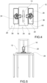
- the test unit 12 further comprises at least one measuring sensor 18, 20, adapted for measuring a change in diameter in a transverse direction y which is transversal to the longitudinal axis x.
- test unit 12 comprises a programmable control unit 22 operatively connected to the at least one measuring sensor 18, 20 and configured to correlate a diameter change measured by the at least one measuring sensor 18, 20 in the presence of a predetermined axial force with reference internal pressure values to which such measured diameter change and such predetermined axial force correspond.
- the at least one sensor 18, 20 can be of the optical type.
- the at least one sensor 18, 20 may be a laser-type sensor.
- the at least one sensor 18, 20 may be a LH30IX485QP laser-type sensor marketed by Banner Engineering.
- the at least one sensor 18, 20 may be a confocal-type sensor.
- the at least one sensor 18, 20 can be a CHRocodile CLS confocal-type sensor marketed by the company Precitec.
- the at least one measuring sensor 18, 20 may comprise two measuring sensors 18, 20 arranged substantially opposite to each other along a direction corresponding to a diametrical direction of the cylindrical glass container being tested or of a containment portion thereof.
- the at least one measuring sensor 18, 20 may be arranged on an adjustable support 24, 26 adapted for adjusting the position of the at least one measuring sensor 18, 20 in a direction substantially parallel to the longitudinal direction (x) and/or in a direction substantially parallel to the axis (y).
- the adjustable support 24, 26 may be, for example, a micrometric slide that allows adjustment of the position along at least one Cartesian axis, and adjustment by rotation about at least one of the Cartesian axes.
- the adjustable support 24, 26 may be a micrometric slide that allows position adjustment along three Cartesian axes, and adjustment by rotation about the three Cartesian axes.
- the measuring sensors are adjusted in terms of position and signal strength by means of a dedicated computer program.
- the adjustable support 24, 26 may be adapted to allow a positioning of the at least one measuring sensor 18, 20 such as to enable a measurement at the cylindrical glass container 100 between the shoulder 104 of the container and 2 cm in the direction of the plunger 102.
- the support 14 may be made of rigid or semi-rigid material. According to a possible embodiment, the support 14 may be made of polymeric material, possibly reinforced with fibres. In alternative embodiments, the support 14 may be made of metal, e.g. aluminium.
- the support 14 may comprise a fixing base 142 and a containment portion 144.
- the containment portion 144 of the support 14 may be adapted to prevent glass-to-glass or glass-to-metal contact, through the use of inserts (not shown) made of a polymeric material, arranged on the inner surface 148 of the containment portion 144 intended to accommodate the cylindrical glass container 100.
- the support 14 may be connected to a first test bench 28 for example by means of screws (not shown) and using through holes 146 provided at the fixing base 142.
- the containment portion 144 may comprise a substantially cylindrical inner surface 148, at least one measuring aperture 150, 162 adapted for placing in visual communication the inside of the containment portion 144 with the at least one measuring sensor 18, 20.
- the support 14 can be arranged with longitudinal support means 154 for supporting the cylindrical glass container 100.
- the longitudinal support means 154 for supporting said cylindrical glass container may be adapted for supporting an intermediate portion of said container or an end portion.
- the longitudinal support means 154 may be adapted for supporting a shoulder area of the syringe, or a flange area.
- the inner surface 148 of the support 14 may be counter-shaped with respect to the cylindrical glass container to be placed within it.
- the inner surface 148 may be designed so that, in use, the distance between the inner surface 148 and the cylindrical glass container is less than 0.2 mm.
- the support 14 may be provided with a drainage hole 156 adapted for ensuring the exit of fluid from the container following the impact of the piston 16.
- the drainage hole 156 may be arranged at the fixing base 142 and so as to allow fluid communication between the outside and the inner surface 148 of the containment portion 144.
- stiffening wings 143 may be provided between the fixing base 142 and the containment portion 144, the stiffening wings 143 being adapted for making the containment portion 144 more stable with respect to the fixing base 142.
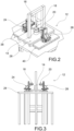
- the support 14, the piston 16 and the related support structure 158 can be arranged on a first test bench 28.
- the first test bench 28 may have a substantially square base and be arranged with three legs on two opposite sides.
- the support 14, the piston 16 and the related support structure 158 may be arranged on a base structure 32 located above the support surface 34 of the first test bench 28.
- the measuring sensors 18, 20 are arranged on a second test bench 36, independent from the first test bench 28.
- the adjustable supports 24, 26 and thus the measuring sensors 18, 20 are arranged on a second test bench 36 independent from the first test bench 28.
- the support surface 34 of the first test bench 28 comprises at least one through opening 38, 40 from which said second test bench 36 protrudes with said at least one adjustable support 24, 26.
- the support surface 34 of the first test bench 28 comprises two through openings 38, 40 from which said second test bench 36 protrudes with said adjustable supports 24, 26.
- the second test bench 36 can be divided into two separate benches so that each adjustable support 24, 26 is supported independently.
- the first test bench 28 may be physically separated from the second test bench 36 so that any vibrations are not transmitted to the second test bench 36 on which the at least one measuring sensor 18, 20 is positioned.
- the first test bench 28 constituting a support for the piston (16) and the second test bench 36 constituting a support for the at least one sensor 18,20 may be separate and/or vibrationally isolated from each other.
- the support comprises a force measuring device 29 adapted for measuring the force applied by said piston on a syringe arranged in said support.
- the force measuring device can be provided, for example, on the support 14 or on a fixed part of the piston 16.
- the force measuring device can be a load cell, for example.
- the process for measuring the internal pressure in a cylindrical glass container 100 comprises:
- the piston 16 of the test unit 12 simulates the spring-piston system that activates the plunger 102.
- the impact speed of the piston 16 may be adjusted to achieve substantially the same impact force as the spring-piston system activating the plunger 102. In this case, due to a lower mass of the syringe spring-piston system with respect to the piston 16, the impact speed of the piston 16 on the plunger 102 will be lower.
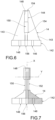
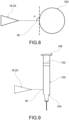
- the measuring sensor 18, 20 is pointed so as to measure this distance, i.e. at the point closest to the sensor itself (as seen in the example shown in figures 8 and 9 ).
- the angle ⁇ between the pointing trajectory of the measuring sensor 18, 20 and the tangent to the circumference at the observation point 30 can be 90° ⁇ 10°, preferably 90° ⁇ 5°, even more preferably 90° ⁇ 1°.
- test unit 12 is prepared with two measuring sensors 18, 20:
- the observation point 30 may be selected around 5 mm above the shoulder.
- the distance between the measuring sensor 18, 20 and the observation point 30 can be decided according to the distance which creates the highest strength of the acquired signal.
- the control unit 22 can be adapted to display the signal strength in order to adjust the position and thus the distance of the measuring sensor 18, 20 with respect to the container 100.
- the calibration step (b) can be performed with pressure sensors and strain gauges.
- the measuring sensors allow the variation of the diameter of the outer wall of the container due to the impact of the piston with the plunger to be obtained.
- Strain gauges can be used to obtain a deformation measurement of the outer wall of the container in both axial and circumferential directions.
- Pressure sensors allow direct measurement of the internal pressure.
- the peak of the diameter changes obtained with the measurement sensors were validated by comparison with peak deformation values obtained from measurements with strain gauges and pressure sensors, for different piston impact speeds.
- Calibration can then be carried out directly by the user, e.g. by means of a predetermined procedure.
- Calibration can be performed by placing the strain gauges at the observation point 30 of the measuring sensor 18, 20.
- the step of validating the models used can be carried out taking into account various types of containers 12 and parameters, such as: different filling volumes of the container, viscosity of the liquid used, presence or absence of air gap, different types of springs.
- the use of two measuring sensors 18, 20 makes it possible to evaluate the diameter variation net of system vibrations, translations, bending of the container.
- the calibration step may comprise the following steps:
- the measurement step (c) may comprise the steps of:
- the method makes an indirect measurement of the internal pressure in a container by measuring the change in diameter.
- test unit and a process have been made available which allow a non-contact measurement of the internal pressure in a cylindrical glass container.
- test unit can for example be provided directly in a production line, since there is no need for operations to be performed manually by operators, such as the application of strain gauges in the processes of the prior art.
- the system is not affected by problems related to the positioning of strain gauges on the outer surface of the container. Accordingly, the measurement carried out with the test unit and the process of the present invention can be easy repeated, and measurements can be compared between containers of the same type.
Landscapes
- Physics & Mathematics (AREA)
- General Physics & Mathematics (AREA)
- Chemical & Material Sciences (AREA)
- Analytical Chemistry (AREA)
- Health & Medical Sciences (AREA)
- Life Sciences & Earth Sciences (AREA)
- Biochemistry (AREA)
- General Health & Medical Sciences (AREA)
- Immunology (AREA)
- Pathology (AREA)
- Electromagnetism (AREA)
- Measuring Fluid Pressure (AREA)
Claims (15)
- Testeinheit (12) zur Messung des Innendrucks in einem zylindrischen Glasbehälter (100), umfassend:- einen Träger (14), der zur Aufnahme eines zylindrischen Glasbehälters (100) während einer Testphase ausgelegt ist, um eine Längsachse (x) zu definieren, die im Gebrauch einer Längsachse eines zylindrischen Glasbehälters (100) entspricht, der in dem Träger (14) angeordnet ist;- einen Kolben (16), der zum selektiven Ausüben einer vorbestimmten axialen Kraft in einer Längsrichtung im Wesentlichen parallel zu der Längsachse (x) ausgelegt ist, wobei der Kolben zum Betätigen eines Stempels (102) ausgelegt ist, der entlang der Längsachse innerhalb eines Behälters (100) beweglich ist, der in dem Träger (14) angeordnet ist;- mindestens einen Messsensor (18, 20), der zur Messung einer Durchmesseränderung in einer Querrichtung (y), die quer zu der Längsachse (x) verläuft, ausgelegt ist;- eine programmierbare Steuereinheit (22), die betriebswirksam mit dem mindestens einen Messsensor (18, 20) verbunden und dazu konfiguriert ist, eine von dem mindestens einen Messsensor (18, 20) bei Vorliegen einer vorbestimmten Axialkraft gemessene Durchmesseränderung mit Referenzinnendruckwerten zu korrelieren, denen die gemessene Durchmesseränderung und die vorbestimmte Axialkraft entsprechen.
- Testeinheit (12) nach Anspruch 1, dadurch gekennzeichnet, dass der mindestens eine Messsensor (18, 20) vom optischen Typ ist.
- Testeinheit (12) nach einem der Ansprüche 1-2, dadurch gekennzeichnet, dass der zumindest eine Messsensor (18, 20) zwei Messsensoren (18, 20) umfasst, die in einer diametralen Richtung im Wesentlichen gegenüberliegend angeordnet sind.
- Testeinheit (12) nach einem der Ansprüche 1-3, dadurch gekennzeichnet, dass der mindestens eine Messsensor (18, 20) an einem verstellbaren Träger (24, 26) angeordnet ist, der dazu ausgelegt ist, die Position des mindestens einen Messsensors (18, 20) in einer Richtung im Wesentlichen parallel zur Längsrichtung (x) und/oder in einer Richtung im Wesentlichen parallel zur Achse (y) einzustellen.
- Testeinheit (12) nach einem der Ansprüche 1-4, dadurch gekennzeichnet, dass der mindestens eine Messsensor (18, 20) zur Messung einer Durchmesseränderung in einer Richtung im Wesentlichen senkrecht zu der Längsachse (x) ausgelegt ist.
- Testeinheit (12) nach einem der Ansprüche 1-5, dadurch gekennzeichnet, dass der Träger (14) eine Befestigungsbasis (142) und einen Enthalteabschnitt (144) umfasst, wobei der Enthalteabschnitt (144) eine im Wesentlichen zylindrische Innenfläche (148) und mindestens eine Messöffnung (150, 162) umfasst, die dazu ausgelegt ist, das Innere des Enthalteabschnitts (144) mit dem mindestens einen Messsensor (18, 20) in Sichtkommunikation zu bringen.
- Testeinheit (12) nach einem der Ansprüche 1-6, dadurch gekennzeichnet, dass der Träger (14) mit Längstragemitteln (154) zum Tragen des zylindrischen Glasbehälters (100) versehen und zum Tragen eines Zwischenabschnitts des Behälters oder eines Endabschnitts davon ausgelegt ist.
- Testeinheit (12) nach einem der Ansprüche 1-7, dadurch gekennzeichnet, dass der Träger (14) mit einem Ablaufloch (156) versehen ist, das ausgelegt ist, den Austritt von Fluid aus dem Behälter nach dem Aufprall des Kolbens (16) zu gewährleisten, wobei das Ablaufloch (156) an der Befestigungsbasis (142) angeordnet ist, um eine Fluidkommunikation zwischen der Außenseite und der Innenfläche (148) des Enthalteabschnitts (144) zu ermöglichen.
- Testeinheit (12) nach einem der Ansprüche 1-8, dadurch gekennzeichnet, dass sie einen ersten Prüfstand (28), der einen Träger für den Kolben (16) bildet, und einen zweiten Prüfstand (36) umfasst, der eine Trägereinheit für den mindestens einen Messsensor (18,20) bildet, wobei der erste Prüfstand (28) und der zweite Prüfstand (36) voneinander getrennt und/oder schwingungsisoliert sind.
- Testeinheit (12) nach einem der Ansprüche 1-9, dadurch gekennzeichnet, dass die Steuereinheit (22) konfiguriert ist, um Schubwerte des Kolbens (16) bereitzustellen, die mit entsprechenden tatsächlichen Schubwerten korreliert sind.
- Testeinheit (12) nach einem der Ansprüche 1-10, dadurch gekennzeichnet, dass die Steuereinheit (22) konfiguriert ist, um Messungen mindestens im Bereich zwischen 2 ms vor der Betätigung des Stempels (102) des zylindrischen Glasbehälters (100) und 30 ms nach der Betätigung des Stempels (102) der Spritze (100) durchzuführen, vorzugsweise zwischen 5 ms und 15 ms.
- Testeinheit (12) nach einem der Ansprüche 1-11, dadurch gekennzeichnet, dass der Träger (14) eine Kraftmessvorrichtung (29) umfasst, die zur Messung der Kraft ausgelegt ist, die von dem Kolben (16) auf einen in dem Träger (14) angeordneten zylindrischen Glasbehälter (100) aufgebracht wird.
- Verfahren zur Messung des Innendrucks in einem zylindrischen Glasbehälter (100), umfassend:- (a) einen anfänglichen Schritt des Anordnens einer Testeinheit (12) zur Messung des Innendrucks in einem zylindrischen Glasbehälter (100) nach einem der Ansprüche 1 - 12;- (b) einen Kalibrierungsschritt zum Kalibrieren der Testeinheit (12), bei dem eine bestimmte Art von zylindrischem Glasbehälter (100) einer Messung durch Einsetzen einer Druckmessvorrichtung in den Behälter (100) unterzogen wird, wobei in dem Kalibrierungsschritt vorbestimmte Axialkräfte durch den Kolben (16) aufgebracht werden, wobei jeder Axialkraftwert mit einer entsprechenden Art von Fluid, das in dem Behälter (100) enthalten ist, einer entsprechenden Durchmesservariation des Behälters (100), der in dem Träger (14) angeordnet ist, und einem entsprechenden Druckwert, der in dem Behälter (100) gemessen wird, korreliert;- (c) einen Schritt des Messens einer Durchmesseränderung eines zylindrischen Glasbehälters (100), der in dem Träger (14) angeordnet ist, mittels mindestens eines Messsensors (18, 20);- (d) einen Verarbeitungsschritt, bei dem die programmierbare Steuereinheit (22), die mit dem mindestens einen Messsensor (26, 28) betriebswirksam verbunden ist, eine von dem mindestens einen Messsensor (26, 28) bei Vorliegen einer vorbestimmten Axialkraft gemessene Durchmesseränderung mit im Kalibrierungsschritt gemessenen Referenzinnendruckwerten korreliert, denen eine solche gemessene Durchmesseränderung und eine solche vorbestimmte Axialkraft entsprechen.
- Verfahren zur Messung des Innendrucks in einem zylindrischen Glasbehälter (100) nach Anspruch 13, dadurch gekennzeichnet, dass der Kalibrierungsschritt die folgenden Schritte umfasst:- Beginn der Kalibrierung;- Installation von Dehnungsmessstreifen und/oder Installation von Drucksensoren;- Vergleichen mit Messungen, die durch die Messsensoren (18, 20) erhalten werden;- Überprüfen der Einhaltung eines mathematischen Modells;- Ende der Kalibrierung.
- Verfahren zur Messung des Innendrucks in einem zylindrischen Glasbehälter (100) nach einem der Ansprüche 13-14, dadurch gekennzeichnet, dass der Messschritt (c) die folgenden Schritte umfasst:- Platzieren des Behälters (100) in den Träger (14);- Überprüfen einer vertikalen Ausrichtung zwischen Behälter (100) und Kolben (16);- Überprüfen der Positionierung mindestens eines Messsensors (18, 20);- Starten der Datenerfassung durch den mindestens einen Messsensor (18, 20);- Kolbenbetätigung (16);- Ende der Erfassung;- Speichern der gesammelten Daten;- Erhalten der maximalen Durchmesservariation durch Kombinieren der Signale, die aus dem mindestens einen Messsensor (18, 20) kommen;- Berechnen des Innendrucks bei der maximalen Durchmesseränderung unter Verwendung der Theorie dicker Schalen in einem linearen elastischen Feld; und- Erhalten der maximalen Durchmesservariation und des maximalen theoretischen Referenzdrucks in Bezug darauf im Kalibrierungsschritt.
Applications Claiming Priority (1)
| Application Number | Priority Date | Filing Date | Title |
|---|---|---|---|
| IT102021000013643A IT202100013643A1 (it) | 2021-05-26 | 2021-05-26 | Unità di test e procedimento per la misurazione della pressione interna in un contenitore cilindrico in vetro |
Publications (3)
| Publication Number | Publication Date |
|---|---|
| EP4095504A1 EP4095504A1 (de) | 2022-11-30 |
| EP4095504C0 EP4095504C0 (de) | 2024-04-10 |
| EP4095504B1 true EP4095504B1 (de) | 2024-04-10 |
Family
ID=77801791
Family Applications (1)
| Application Number | Title | Priority Date | Filing Date |
|---|---|---|---|
| EP22174914.6A Active EP4095504B1 (de) | 2021-05-26 | 2022-05-23 | Testeinheit und verfahren zur messung des innendrucks in einem zylindrischen glasbehälter |
Country Status (4)
| Country | Link |
|---|---|
| US (1) | US11714017B2 (de) |
| EP (1) | EP4095504B1 (de) |
| CN (1) | CN115406573B (de) |
| IT (1) | IT202100013643A1 (de) |
Families Citing this family (1)
| Publication number | Priority date | Publication date | Assignee | Title |
|---|---|---|---|---|
| CN119063900B (zh) * | 2024-08-30 | 2025-04-15 | 哈尔滨工业大学(威海) | 内孤立波作用力测量装置、系统及方法 |
Family Cites Families (4)
| Publication number | Priority date | Publication date | Assignee | Title |
|---|---|---|---|---|
| US4815313A (en) * | 1987-11-16 | 1989-03-28 | Abbott Laboratories | Syringe pressure calibration reference |
| AU2005235438B2 (en) * | 2004-04-27 | 2011-04-28 | Imaxeon Pty Ltd | Medical fluid injector |
| JP6146875B2 (ja) * | 2011-10-11 | 2017-06-14 | ホスピテック レスピレーション リミテッド | 圧力調節注射器 |
| CN107949407B (zh) * | 2015-08-28 | 2021-01-12 | 拜耳医药保健有限公司 | 用于注射器流体填充验证和动力注入器系统特征的图像识别的系统及方法 |
-
2021
- 2021-05-26 IT IT102021000013643A patent/IT202100013643A1/it unknown
-
2022
- 2022-05-23 EP EP22174914.6A patent/EP4095504B1/de active Active
- 2022-05-26 CN CN202210586301.1A patent/CN115406573B/zh active Active
- 2022-05-26 US US17/804,105 patent/US11714017B2/en active Active
Also Published As
| Publication number | Publication date |
|---|---|
| US11714017B2 (en) | 2023-08-01 |
| CN115406573B (zh) | 2025-04-22 |
| IT202100013643A1 (it) | 2022-11-26 |
| US20220381637A1 (en) | 2022-12-01 |
| EP4095504C0 (de) | 2024-04-10 |
| EP4095504A1 (de) | 2022-11-30 |
| CN115406573A (zh) | 2022-11-29 |
Similar Documents
| Publication | Publication Date | Title |
|---|---|---|
| US9581533B2 (en) | Modular hardness testing machine | |
| CN112098981B (zh) | 一种激光位移传感器动态幅值校准装置 | |
| CN110082222B (zh) | 分体式三维压力装置及应变波形图采集方法 | |
| US9410864B2 (en) | Method and device for determining the static unbalance | |
| EP4095504B1 (de) | Testeinheit und verfahren zur messung des innendrucks in einem zylindrischen glasbehälter | |
| EP3314233A1 (de) | Einkerbungsvorrichtung, instrumentiertes messsystem und verfahren zur bestimmung der mechanischen eigenschaften von materialien anhand des einkerbungsverfahrens | |
| KR102434644B1 (ko) | 토션미터 교정장치 및 교정방법 | |
| CA2368847A1 (en) | Method for reducing test cycle time and for improving measuring accuracy at a leak testing process | |
| JP2024054329A (ja) | 力測定アセンブリ、このような力測定アセンブリを備えた力測定装置およびこのような力測定アセンブリを用いた方法 | |
| CN203758495U (zh) | 一种适用于岩石变形测试传感器标定的夹持装置 | |
| CN112781812A (zh) | 隔膜压缩机金属膜片疲劳测试方法 | |
| CN107532958A (zh) | 变形测量扭矩仪 | |
| CN113740145B (zh) | 一种弹性体材料体积模量测试装置与方法 | |
| CN114136624B (zh) | 一种方向可调的推力测量台架中心加载校准装置 | |
| US3397572A (en) | Device for measuring stressstrain curve | |
| CN106052529B (zh) | Pcb沉孔的检测方法 | |
| US3040435A (en) | Testing machines | |
| CN116380640A (zh) | 一种可长期力监测的材料松弛试验加载装置 | |
| Tian et al. | Calibration of cyclic force with inertial force correction to a fatigue testing machine | |
| CN209783814U (zh) | 一种力值和位移的多用途校准装置 | |
| CN223139259U (zh) | 一种带对齐检测功能的剪切盒 | |
| CN223650294U (en) | Viscoelastic material test support and test system | |
| JPH0454882B2 (de) | ||
| Krishnan et al. | Calibration of micropipettes through gravimetric solution and its beneficial impact on research | |
| CN219891010U (zh) | 一种拉伸试验机校准辅助工具 |
Legal Events
| Date | Code | Title | Description |
|---|---|---|---|
| PUAI | Public reference made under article 153(3) epc to a published international application that has entered the european phase |
Free format text: ORIGINAL CODE: 0009012 |
|
| STAA | Information on the status of an ep patent application or granted ep patent |
Free format text: STATUS: THE APPLICATION HAS BEEN PUBLISHED |
|
| AK | Designated contracting states |
Kind code of ref document: A1 Designated state(s): AL AT BE BG CH CY CZ DE DK EE ES FI FR GB GR HR HU IE IS IT LI LT LU LV MC MK MT NL NO PL PT RO RS SE SI SK SM TR |
|
| STAA | Information on the status of an ep patent application or granted ep patent |
Free format text: STATUS: REQUEST FOR EXAMINATION WAS MADE |
|
| P01 | Opt-out of the competence of the unified patent court (upc) registered |
Effective date: 20230508 |
|
| 17P | Request for examination filed |
Effective date: 20230526 |
|
| RBV | Designated contracting states (corrected) |
Designated state(s): AL AT BE BG CH CY CZ DE DK EE ES FI FR GB GR HR HU IE IS IT LI LT LU LV MC MK MT NL NO PL PT RO RS SE SI SK SM TR |
|
| GRAP | Despatch of communication of intention to grant a patent |
Free format text: ORIGINAL CODE: EPIDOSNIGR1 |
|
| STAA | Information on the status of an ep patent application or granted ep patent |
Free format text: STATUS: GRANT OF PATENT IS INTENDED |
|
| RIC1 | Information provided on ipc code assigned before grant |
Ipc: G01L 27/00 20060101ALI20231016BHEP Ipc: G01L 9/00 20060101ALI20231016BHEP Ipc: A61M 5/00 20060101ALI20231016BHEP Ipc: A61M 5/178 20060101ALI20231016BHEP Ipc: G01N 3/12 20060101ALI20231016BHEP Ipc: G01M 3/36 20060101AFI20231016BHEP |
|
| INTG | Intention to grant announced |
Effective date: 20231108 |
|
| GRAS | Grant fee paid |
Free format text: ORIGINAL CODE: EPIDOSNIGR3 |
|
| GRAA | (expected) grant |
Free format text: ORIGINAL CODE: 0009210 |
|
| STAA | Information on the status of an ep patent application or granted ep patent |
Free format text: STATUS: THE PATENT HAS BEEN GRANTED |
|
| AK | Designated contracting states |
Kind code of ref document: B1 Designated state(s): AL AT BE BG CH CY CZ DE DK EE ES FI FR GB GR HR HU IE IS IT LI LT LU LV MC MK MT NL NO PL PT RO RS SE SI SK SM TR |
|
| REG | Reference to a national code |
Ref country code: GB Ref legal event code: FG4D |
|
| REG | Reference to a national code |
Ref country code: CH Ref legal event code: EP |
|
| REG | Reference to a national code |
Ref country code: DE Ref legal event code: R096 Ref document number: 602022002766 Country of ref document: DE |
|
| REG | Reference to a national code |
Ref country code: IE Ref legal event code: FG4D |
|
| U01 | Request for unitary effect filed |
Effective date: 20240416 |
|
| U07 | Unitary effect registered |
Designated state(s): AT BE BG DE DK EE FI FR IT LT LU LV MT NL PT SE SI Effective date: 20240423 |
|
| P04 | Withdrawal of opt-out of the competence of the unified patent court (upc) registered |
Effective date: 20240419 |
|
| U20 | Renewal fee for the european patent with unitary effect paid |
Year of fee payment: 3 Effective date: 20240625 |
|
| PG25 | Lapsed in a contracting state [announced via postgrant information from national office to epo] |
Ref country code: IS Free format text: LAPSE BECAUSE OF FAILURE TO SUBMIT A TRANSLATION OF THE DESCRIPTION OR TO PAY THE FEE WITHIN THE PRESCRIBED TIME-LIMIT Effective date: 20240810 |
|
| PG25 | Lapsed in a contracting state [announced via postgrant information from national office to epo] |
Ref country code: HR Free format text: LAPSE BECAUSE OF FAILURE TO SUBMIT A TRANSLATION OF THE DESCRIPTION OR TO PAY THE FEE WITHIN THE PRESCRIBED TIME-LIMIT Effective date: 20240410 |
|
| PG25 | Lapsed in a contracting state [announced via postgrant information from national office to epo] |
Ref country code: GR Free format text: LAPSE BECAUSE OF FAILURE TO SUBMIT A TRANSLATION OF THE DESCRIPTION OR TO PAY THE FEE WITHIN THE PRESCRIBED TIME-LIMIT Effective date: 20240711 |
|
| PG25 | Lapsed in a contracting state [announced via postgrant information from national office to epo] |
Ref country code: ES Free format text: LAPSE BECAUSE OF FAILURE TO SUBMIT A TRANSLATION OF THE DESCRIPTION OR TO PAY THE FEE WITHIN THE PRESCRIBED TIME-LIMIT Effective date: 20240410 |
|
| PG25 | Lapsed in a contracting state [announced via postgrant information from national office to epo] |
Ref country code: PL Free format text: LAPSE BECAUSE OF FAILURE TO SUBMIT A TRANSLATION OF THE DESCRIPTION OR TO PAY THE FEE WITHIN THE PRESCRIBED TIME-LIMIT Effective date: 20240410 |
|
| PG25 | Lapsed in a contracting state [announced via postgrant information from national office to epo] |
Ref country code: PL Free format text: LAPSE BECAUSE OF FAILURE TO SUBMIT A TRANSLATION OF THE DESCRIPTION OR TO PAY THE FEE WITHIN THE PRESCRIBED TIME-LIMIT Effective date: 20240410 Ref country code: NO Free format text: LAPSE BECAUSE OF FAILURE TO SUBMIT A TRANSLATION OF THE DESCRIPTION OR TO PAY THE FEE WITHIN THE PRESCRIBED TIME-LIMIT Effective date: 20240710 Ref country code: IS Free format text: LAPSE BECAUSE OF FAILURE TO SUBMIT A TRANSLATION OF THE DESCRIPTION OR TO PAY THE FEE WITHIN THE PRESCRIBED TIME-LIMIT Effective date: 20240810 Ref country code: HR Free format text: LAPSE BECAUSE OF FAILURE TO SUBMIT A TRANSLATION OF THE DESCRIPTION OR TO PAY THE FEE WITHIN THE PRESCRIBED TIME-LIMIT Effective date: 20240410 Ref country code: GR Free format text: LAPSE BECAUSE OF FAILURE TO SUBMIT A TRANSLATION OF THE DESCRIPTION OR TO PAY THE FEE WITHIN THE PRESCRIBED TIME-LIMIT Effective date: 20240711 Ref country code: ES Free format text: LAPSE BECAUSE OF FAILURE TO SUBMIT A TRANSLATION OF THE DESCRIPTION OR TO PAY THE FEE WITHIN THE PRESCRIBED TIME-LIMIT Effective date: 20240410 Ref country code: RS Free format text: LAPSE BECAUSE OF FAILURE TO SUBMIT A TRANSLATION OF THE DESCRIPTION OR TO PAY THE FEE WITHIN THE PRESCRIBED TIME-LIMIT Effective date: 20240710 |
|
| P05 | Withdrawal of opt-out of the competence of the unified patent court (upc) changed |
Free format text: CASE NUMBER: APP_21290/2024 Effective date: 20240423 |
|
| REG | Reference to a national code |
Ref country code: DE Ref legal event code: R097 Ref document number: 602022002766 Country of ref document: DE |
|
| PG25 | Lapsed in a contracting state [announced via postgrant information from national office to epo] |
Ref country code: CZ Free format text: LAPSE BECAUSE OF FAILURE TO SUBMIT A TRANSLATION OF THE DESCRIPTION OR TO PAY THE FEE WITHIN THE PRESCRIBED TIME-LIMIT Effective date: 20240410 |
|
| PG25 | Lapsed in a contracting state [announced via postgrant information from national office to epo] |
Ref country code: RO Free format text: LAPSE BECAUSE OF FAILURE TO SUBMIT A TRANSLATION OF THE DESCRIPTION OR TO PAY THE FEE WITHIN THE PRESCRIBED TIME-LIMIT Effective date: 20240410 Ref country code: SK Free format text: LAPSE BECAUSE OF FAILURE TO SUBMIT A TRANSLATION OF THE DESCRIPTION OR TO PAY THE FEE WITHIN THE PRESCRIBED TIME-LIMIT Effective date: 20240410 |
|
| PG25 | Lapsed in a contracting state [announced via postgrant information from national office to epo] |
Ref country code: SM Free format text: LAPSE BECAUSE OF FAILURE TO SUBMIT A TRANSLATION OF THE DESCRIPTION OR TO PAY THE FEE WITHIN THE PRESCRIBED TIME-LIMIT Effective date: 20240410 |
|
| PG25 | Lapsed in a contracting state [announced via postgrant information from national office to epo] |
Ref country code: SM Free format text: LAPSE BECAUSE OF FAILURE TO SUBMIT A TRANSLATION OF THE DESCRIPTION OR TO PAY THE FEE WITHIN THE PRESCRIBED TIME-LIMIT Effective date: 20240410 Ref country code: SK Free format text: LAPSE BECAUSE OF FAILURE TO SUBMIT A TRANSLATION OF THE DESCRIPTION OR TO PAY THE FEE WITHIN THE PRESCRIBED TIME-LIMIT Effective date: 20240410 Ref country code: RO Free format text: LAPSE BECAUSE OF FAILURE TO SUBMIT A TRANSLATION OF THE DESCRIPTION OR TO PAY THE FEE WITHIN THE PRESCRIBED TIME-LIMIT Effective date: 20240410 Ref country code: CZ Free format text: LAPSE BECAUSE OF FAILURE TO SUBMIT A TRANSLATION OF THE DESCRIPTION OR TO PAY THE FEE WITHIN THE PRESCRIBED TIME-LIMIT Effective date: 20240410 Ref country code: MC Free format text: LAPSE BECAUSE OF FAILURE TO SUBMIT A TRANSLATION OF THE DESCRIPTION OR TO PAY THE FEE WITHIN THE PRESCRIBED TIME-LIMIT Effective date: 20240410 |
|
| PLBE | No opposition filed within time limit |
Free format text: ORIGINAL CODE: 0009261 |
|
| STAA | Information on the status of an ep patent application or granted ep patent |
Free format text: STATUS: NO OPPOSITION FILED WITHIN TIME LIMIT |
|
| 26N | No opposition filed |
Effective date: 20250113 |
|
| PG25 | Lapsed in a contracting state [announced via postgrant information from national office to epo] |
Ref country code: IE Free format text: LAPSE BECAUSE OF NON-PAYMENT OF DUE FEES Effective date: 20240523 |
|
| U20 | Renewal fee for the european patent with unitary effect paid |
Year of fee payment: 4 Effective date: 20250528 |
|
| PGFP | Annual fee paid to national office [announced via postgrant information from national office to epo] |
Ref country code: CH Payment date: 20250601 Year of fee payment: 4 |
|
| PG25 | Lapsed in a contracting state [announced via postgrant information from national office to epo] |
Ref country code: CY Free format text: LAPSE BECAUSE OF FAILURE TO SUBMIT A TRANSLATION OF THE DESCRIPTION OR TO PAY THE FEE WITHIN THE PRESCRIBED TIME-LIMIT; INVALID AB INITIO Effective date: 20220523 |
|
| PG25 | Lapsed in a contracting state [announced via postgrant information from national office to epo] |
Ref country code: HU Free format text: LAPSE BECAUSE OF FAILURE TO SUBMIT A TRANSLATION OF THE DESCRIPTION OR TO PAY THE FEE WITHIN THE PRESCRIBED TIME-LIMIT; INVALID AB INITIO Effective date: 20220523 |