EP4095406B1 - Flexible kopplungsanordnung - Google Patents
Flexible kopplungsanordnung Download PDFInfo
- Publication number
- EP4095406B1 EP4095406B1 EP22181864.4A EP22181864A EP4095406B1 EP 4095406 B1 EP4095406 B1 EP 4095406B1 EP 22181864 A EP22181864 A EP 22181864A EP 4095406 B1 EP4095406 B1 EP 4095406B1
- Authority
- EP
- European Patent Office
- Prior art keywords
- shaft
- flexible
- coupling
- quill shaft
- coupling assembly
- Prior art date
- Legal status (The legal status is an assumption and is not a legal conclusion. Google has not performed a legal analysis and makes no representation as to the accuracy of the status listed.)
- Active
Links
Images


Classifications
-
- F—MECHANICAL ENGINEERING; LIGHTING; HEATING; WEAPONS; BLASTING
- F16—ENGINEERING ELEMENTS AND UNITS; GENERAL MEASURES FOR PRODUCING AND MAINTAINING EFFECTIVE FUNCTIONING OF MACHINES OR INSTALLATIONS; THERMAL INSULATION IN GENERAL
- F16D—COUPLINGS FOR TRANSMITTING ROTATION; CLUTCHES; BRAKES
- F16D3/00—Yielding couplings, i.e. with means permitting movement between the connected parts during the drive
- F16D3/005—Yielding couplings, i.e. with means permitting movement between the connected parts during the drive incorporating leaf springs, flexible parts of reduced thickness or the like acting as pivots
-
- F—MECHANICAL ENGINEERING; LIGHTING; HEATING; WEAPONS; BLASTING
- F16—ENGINEERING ELEMENTS AND UNITS; GENERAL MEASURES FOR PRODUCING AND MAINTAINING EFFECTIVE FUNCTIONING OF MACHINES OR INSTALLATIONS; THERMAL INSULATION IN GENERAL
- F16D—COUPLINGS FOR TRANSMITTING ROTATION; CLUTCHES; BRAKES
- F16D3/00—Yielding couplings, i.e. with means permitting movement between the connected parts during the drive
- F16D3/02—Yielding couplings, i.e. with means permitting movement between the connected parts during the drive adapted to specific functions
- F16D3/04—Yielding couplings, i.e. with means permitting movement between the connected parts during the drive adapted to specific functions specially adapted to allow radial displacement, e.g. Oldham couplings
-
- F—MECHANICAL ENGINEERING; LIGHTING; HEATING; WEAPONS; BLASTING
- F16—ENGINEERING ELEMENTS AND UNITS; GENERAL MEASURES FOR PRODUCING AND MAINTAINING EFFECTIVE FUNCTIONING OF MACHINES OR INSTALLATIONS; THERMAL INSULATION IN GENERAL
- F16D—COUPLINGS FOR TRANSMITTING ROTATION; CLUTCHES; BRAKES
- F16D3/00—Yielding couplings, i.e. with means permitting movement between the connected parts during the drive
- F16D3/16—Universal joints in which flexibility is produced by means of pivots or sliding or rolling connecting parts
- F16D3/26—Hooke's joints or other joints with an equivalent intermediate member to which each coupling part is pivotally or slidably connected
- F16D3/30—Hooke's joints or other joints with an equivalent intermediate member to which each coupling part is pivotally or slidably connected in which the coupling is specially adapted to constant velocity-ratio
- F16D3/34—Hooke's joints or other joints with an equivalent intermediate member to which each coupling part is pivotally or slidably connected in which the coupling is specially adapted to constant velocity-ratio parts being connected by ridges, pins, balls, or the like guided in grooves or between cogs
-
- F—MECHANICAL ENGINEERING; LIGHTING; HEATING; WEAPONS; BLASTING
- F16—ENGINEERING ELEMENTS AND UNITS; GENERAL MEASURES FOR PRODUCING AND MAINTAINING EFFECTIVE FUNCTIONING OF MACHINES OR INSTALLATIONS; THERMAL INSULATION IN GENERAL
- F16D—COUPLINGS FOR TRANSMITTING ROTATION; CLUTCHES; BRAKES
- F16D3/00—Yielding couplings, i.e. with means permitting movement between the connected parts during the drive
- F16D3/50—Yielding couplings, i.e. with means permitting movement between the connected parts during the drive with the coupling parts connected by one or more intermediate members
- F16D3/72—Yielding couplings, i.e. with means permitting movement between the connected parts during the drive with the coupling parts connected by one or more intermediate members with axially-spaced attachments to the coupling parts
-
- F—MECHANICAL ENGINEERING; LIGHTING; HEATING; WEAPONS; BLASTING
- F16—ENGINEERING ELEMENTS AND UNITS; GENERAL MEASURES FOR PRODUCING AND MAINTAINING EFFECTIVE FUNCTIONING OF MACHINES OR INSTALLATIONS; THERMAL INSULATION IN GENERAL
- F16D—COUPLINGS FOR TRANSMITTING ROTATION; CLUTCHES; BRAKES
- F16D3/00—Yielding couplings, i.e. with means permitting movement between the connected parts during the drive
- F16D3/50—Yielding couplings, i.e. with means permitting movement between the connected parts during the drive with the coupling parts connected by one or more intermediate members
- F16D3/76—Yielding couplings, i.e. with means permitting movement between the connected parts during the drive with the coupling parts connected by one or more intermediate members shaped as an elastic ring centered on the axis, surrounding a portion of one coupling part and surrounded by a sleeve of the other coupling part
-
- Y—GENERAL TAGGING OF NEW TECHNOLOGICAL DEVELOPMENTS; GENERAL TAGGING OF CROSS-SECTIONAL TECHNOLOGIES SPANNING OVER SEVERAL SECTIONS OF THE IPC; TECHNICAL SUBJECTS COVERED BY FORMER USPC CROSS-REFERENCE ART COLLECTIONS [XRACs] AND DIGESTS
- Y10—TECHNICAL SUBJECTS COVERED BY FORMER USPC
- Y10T—TECHNICAL SUBJECTS COVERED BY FORMER US CLASSIFICATION
- Y10T403/00—Joints and connections
- Y10T403/70—Interfitted members
- Y10T403/7005—Lugged member, rotary engagement
-
- Y—GENERAL TAGGING OF NEW TECHNOLOGICAL DEVELOPMENTS; GENERAL TAGGING OF CROSS-SECTIONAL TECHNOLOGIES SPANNING OVER SEVERAL SECTIONS OF THE IPC; TECHNICAL SUBJECTS COVERED BY FORMER USPC CROSS-REFERENCE ART COLLECTIONS [XRACs] AND DIGESTS
- Y10—TECHNICAL SUBJECTS COVERED BY FORMER USPC
- Y10T—TECHNICAL SUBJECTS COVERED BY FORMER US CLASSIFICATION
- Y10T403/00—Joints and connections
- Y10T403/70—Interfitted members
- Y10T403/7075—Interfitted members including discrete retainer
- Y10T403/7077—Interfitted members including discrete retainer for telescoping members
- Y10T403/7079—Transverse pin
- Y10T403/7088—Sliding pin
Definitions
- the present invention relates to flexible couplings, and more particularly to a flexible coupling assembly including a quill shaft.
- EP 3 315 807 relates to a flexible diaphragm coupling.
- US 5 755 622 relates to a vibration reducer for a diaphragm coupling.
- US 4 265 099 relates to a flexible coupling.
- GB 929 323 also relates to a flexible coupling.
- a flexible coupling assembly for a power transmission system includes a first shaft defining an axis, configured to connect to a first rotatable member, a first flexible diaphragm coupling configured to have a portion of the first shaft pass axially therethrough, a quill shaft having a circumferential opening configured to receive the first shaft and a locking flange for connecting the quill shaft to the first shaft, the quill shaft further being configured to connect to a second rotating member, and a primary diaphragm coupling shaft positioned radially outward of the quill shaft.
- the quill shaft can include a second mating portion configured for mating with a second rotating member. The second mating portion can be welded to the quill shaft.
- At least one flange adapter can be placed between the primary coupling shaft and the first flexible diaphragm coupling.
- the flange adapter can be welded to the diaphragm coupling and the flange adapter can be bolted to the primary diaphragm coupling shaft.
- the at least one flange adapter includes a pin hole there through arranged perpendicular to the axis can be and aligned with a first shaft pin hole for receiving a pin therein configured to lock relative movement of the first shaft and the flange adapter.
- the first shaft can abut an outer periphery of the first flexible diaphragm coupling.
- the locking flange can include at least one radial protrusion for mating with a cutout within the first mating portion of the quill shaft. At least one radial protrusion can include a wedged portion.
- the primary diaphragm coupling shaft can include a radial displacement limiter in an inner cavity thereof for regulating radial movement of the quill shaft within the primary diaphragm coupling shaft.
- the radial displacement limiter can include a deformable material. The radial displacement limiter encloses the quill shaft and abuts against an inner diameter of the primary diaphragm coupling shaft.
- the quill shaft adjoins a second side of a second flexible diaphragm coupling and passes through the second flexible diaphragm coupling.
- the primary coupling shaft adjoins a first side of the second flexible diaphragm coupling.
- the quill shaft can include a pin hole there through, arranged perpendicular to the axis, and aligned with a primary coupling shaft pin hole for receiving a pin therein configured to lock relative movement of the quill shaft and primary diaphragm coupling shaft during assembly.
- the first shaft can include a pin hole there through, arranged perpendicular to the axis, for receiving a pin therein configured to lock relative movement of the first shaft and the flange adapter.
- the first mating portion can include a pin hole there through.
- the mating portion of the quill shaft includes a larger outer diameter than an outer diameter of a non-mating portion of the quill shaft.
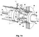
- the quill shaft 108 includes a first mating portion 112 for receiving the locking flange 110 of the first shaft 102 within a circumferential opening 114 (shown in Fig. 1a ).
- the quill shaft 108 is disposed within a primary diaphragm coupling shaft 109.
- the first shaft 102 abuts an outer surface 106a of the first flexible diaphragm coupling 106.
- the primary diaphragm coupling shaft 109 adjoins a first side 116a of a second flexible diaphragm coupling 116 and the quill shaft 108 passes through the second flexible diaphragm coupling 116 and adjoins a second side 116b of the second flexible diaphragm coupling 116.
- Fig. 1a shows the radial protrusions 110b and the cutouts separated during installation.
- At least two flange adapters 118 and 119 are disposed between the primary coupling shaft 109 and the first flexible diaphragm coupling 106 .
- One of the flange adapters 118 can be welded or secured to the flexible diaphragm coupling 106 and the second flange adapter 119 can be welded or secured to the primary diaphragm coupling shaft 109.
- the flange adapters 118, 119 help assure separation required for installation.
- the first shaft 102 also includes a pin hole there through 122e, arranged perpendicular to the axis 104, for receiving another pin therein for locking relative movement of the first shaft 102 and the first flexible diaphragm coupling.
- the pin hole 122e is arranged outside of the locking flange 110.
- the flange adapter 118 also includes a pin hole 122c there through arranged perpendicular to the axis 104 and which is aligned with the first shaft 102 pin hole 122e.
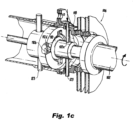
- Fig.1c shows the radial protrusions 110b in a turned and locked position.
- the pins 123 are shown within each of the aligned holes 122e and 122a. The pins are used during installation and are to be removed prior to operating the shaft.
- the features discussed herein eliminate the need for a typical ball and socket assembly within each coupling.
- the typically used ball and socket joints are wear items and need to be replaced after a defined number of service hours.
- the features discussed above greatly improve the Mean Time Between Maintenance Action (MTBMA) versus shafts using ball and socket assemblies.
- MTBMA Mean Time Between Maintenance Action
- the mechanism allowing the quill shaft 108 to be separable eliminates the restriction of prior art where the quill shaft length is based on the length of one flexible coupling.
Landscapes
- Engineering & Computer Science (AREA)
- General Engineering & Computer Science (AREA)
- Mechanical Engineering (AREA)
- Flexible Shafts (AREA)
- Snaps, Bayonet Connections, Set Pins, And Snap Rings (AREA)
Claims (14)
- Flexible Kopplungsanordnung für ein Kraftübertragungssystem, umfassend:eine erste Welle (102), die eine Achse (104) definiert, die dazu konfiguriert ist, mit einem ersten drehbaren Element (101a) verbunden zu werden;eine erste flexible Membrankopplung (106), die dazu konfiguriert ist, dass ein Abschnitt der ersten Welle axial durch sie hindurch verläuft;eine Hohlwelle (108) mit einer Umfangsöffnung, die dazu konfiguriert ist, die erste Welle aufzunehmen, und einem Sperrflansch (110) zum Verbinden der Hohlwelle mit der ersten Welle, wobei die Hohlwelle ferner dazu konfiguriert ist, mit einem zweiten drehenden Element (101b) verbunden zu werden; undeine primäre Membrankopplungswelle (109), die radial außerhalb der Hohlwelle positioniert ist; und dadurch gekennzeichnet, dass:die Hohlwelle (108) an eine zweite Seite einer zweiten flexiblen Membrankopplung angrenzt und durch die zweite flexible Membrankopplung verläuft, undwobei die primäre Kopplungswelle (109) an eine erste Seite der zweiten flexiblen Membrankopplung angrenzt.
- Flexible Kopplungsanordnung nach Anspruch 1, wobei die Hohlwelle einen zweiten Passabschnitt beinhaltet, der zum Zusammenpassen mit einem zweiten drehenden Element konfiguriert ist, und
wobei der zweite Passabschnitt vorzugsweise mit der Hohlwelle verschweißt ist. - Flexible Kopplungsanordnung nach Anspruch 1 oder 2, ferner umfassend mindestens einen Flanschadapter, der zwischen der primären Kopplungswelle und der ersten flexiblen Membrankopplung angeordnet ist, und
wobei der Flanschadapter vorzugsweise mit der Membrankopplung verschweißt ist. - Flexible Kopplungsanordnung nach Anspruch 3, wobei der Flanschadapter mit der primären Membrankopplungswelle verschraubt ist.
- Flexible Kopplungsanordnung nach Anspruch 4, wobei der mindestens eine Flanschadapter ein durch ihn hindurchgehendes, senkrecht zu der Achse angeordnetes und mit einem Stiftloch der ersten Welle ausgerichtetes Stiftloch zum Aufnehmen eines Stifts darin beinhaltet, der dazu konfiguriert ist, eine relative Bewegung der ersten Welle und des Flanschadapters zu sperren.
- Flexible Kopplungsanordnung nach einem der vorhergehenden Ansprüche, wobei die erste Welle an einem Außenumfang der ersten flexiblen Membrankopplung anliegt.
- Flexible Kopplungsanordnung nach einem der vorhergehenden Ansprüche, wobei der Sperrflansch mindestens einen radialen Vorsprung zum Zusammenpassen mit einem Ausschnitt innerhalb des ersten Passabschnitts der Hohlwelle beinhaltet, und
wobei der mindestens eine radiale Vorsprung vorzugsweise einen keilförmigen Abschnitt beinhaltet. - Flexible Kopplungsanordnung nach einem der vorhergehenden Ansprüche, wobei die primäre Membrankopplungswelle einen radialen Verschiebungsbegrenzer in einem inneren Hohlraum von ihr zum Regulieren einer radialen Bewegung der Hohlwelle innerhalb der primären Membrankopplungswelle beinhaltet.
- Flexible Kopplungsanordnung nach Anspruch 8, wobei der radiale Verschiebungsbegrenzer ein verformbares Material beinhaltet.
- Flexible Kopplungsanordnung nach Anspruch 8, wobei der radiale Verschiebungsbegrenzer die Hohlwelle umschließt und an einem Innendurchmesser der primären Membrankopplungswelle anliegt.
- Flexible Kopplungsanordnung nach einem der vorhergehenden Ansprüche, wobei die Hohlwelle ein durch sie hindurchgehendes, senkrecht zu der Achse angeordnetes und mit einem Stiftloch der primären Kopplungswelle ausgerichtetes Stiftloch zum Aufnehmen eines Stifts darin beinhaltet, der dazu konfiguriert ist, eine relative Bewegung der Hohlwelle und der primären Membrankopplungswelle während der Montage zu sperren.
- Flexible Kopplungsanordnung nach einem der vorhergehenden Ansprüche, wobei die erste Welle ein durch sie hindurchgehendes, senkrecht zu der Achse angeordnetes Stiftloch zum Aufnehmen eines Stifts darin beinhaltet, der dazu konfiguriert ist, eine relative Bewegung der ersten Welle und des Flanschadapters zu sperren.
- Flexible Kopplungsanordnung nach einem der vorhergehenden Ansprüche, wobei der erste Passabschnitt ein durch ihn hindurchgehendes Stiftloch beinhaltet.
- Flexible Kopplungsanordnung nach einem der vorhergehenden Ansprüche, wobei der Passabschnitt der Hohlwelle einen größeren Außendurchmesser als ein Außendurchmesser eines Nicht-Passabschnitts der Hohlwelle beinhaltet.
Applications Claiming Priority (2)
| Application Number | Priority Date | Filing Date | Title |
|---|---|---|---|
| US16/403,229 US11408467B2 (en) | 2019-05-03 | 2019-05-03 | Flexible coupling assembly |
| EP19212068.1A EP3734100B1 (de) | 2019-05-03 | 2019-11-28 | Flexible kopplungsanordnung |
Related Parent Applications (1)
| Application Number | Title | Priority Date | Filing Date |
|---|---|---|---|
| EP19212068.1A Division EP3734100B1 (de) | 2019-05-03 | 2019-11-28 | Flexible kopplungsanordnung |
Publications (2)
| Publication Number | Publication Date |
|---|---|
| EP4095406A1 EP4095406A1 (de) | 2022-11-30 |
| EP4095406B1 true EP4095406B1 (de) | 2025-03-19 |
Family
ID=68731798
Family Applications (2)
| Application Number | Title | Priority Date | Filing Date |
|---|---|---|---|
| EP19212068.1A Active EP3734100B1 (de) | 2019-05-03 | 2019-11-28 | Flexible kopplungsanordnung |
| EP22181864.4A Active EP4095406B1 (de) | 2019-05-03 | 2019-11-28 | Flexible kopplungsanordnung |
Family Applications Before (1)
| Application Number | Title | Priority Date | Filing Date |
|---|---|---|---|
| EP19212068.1A Active EP3734100B1 (de) | 2019-05-03 | 2019-11-28 | Flexible kopplungsanordnung |
Country Status (2)
| Country | Link |
|---|---|
| US (3) | US11408467B2 (de) |
| EP (2) | EP3734100B1 (de) |
Families Citing this family (3)
| Publication number | Priority date | Publication date | Assignee | Title |
|---|---|---|---|---|
| US11408467B2 (en) * | 2019-05-03 | 2022-08-09 | Goodrich Corporation | Flexible coupling assembly |
| CN112901740A (zh) * | 2021-01-15 | 2021-06-04 | 杭州宇昌智慧科技有限公司 | 一种用于卷轴的柔性传动系统 |
| US11600506B2 (en) * | 2021-04-23 | 2023-03-07 | Taiwan Semiconductor Manufacturing Company Limited | Wafer pod transfer assembly |
Family Cites Families (18)
| Publication number | Priority date | Publication date | Assignee | Title |
|---|---|---|---|---|
| GB191301201A (en) * | 1913-01-15 | 1914-01-15 | George Lunt | Improvements in Bakers' Ovens. |
| US1871227A (en) * | 1928-08-29 | 1932-08-09 | Cleveland Steel Products Corp | Flexible coupling |
| US2550580A (en) | 1945-01-16 | 1951-04-24 | Power Jets Res & Dev Ltd | Flexible coupling for shafts and the like |
| US2647380A (en) * | 1949-06-24 | 1953-08-04 | Bendix Aviat Corp | Flexible shaft |
| US2917910A (en) * | 1956-07-13 | 1959-12-22 | Thompson Ramo Wooldridge Inc | Coupling |
| GB929323A (en) | 1961-05-17 | 1963-06-19 | Ass Elect Ind | Improved flexible coupling particularly for turbine-generator equipment |
| GB1052336A (de) * | 1962-02-09 | |||
| US4116018A (en) * | 1976-09-16 | 1978-09-26 | The Zeller Corporation | Universal joint |
| CH634133A5 (de) | 1979-02-16 | 1983-01-14 | Maag Zahnraeder & Maschinen Ag | Doppelgelenkkupplung. |
| US4265099A (en) | 1979-03-02 | 1981-05-05 | General Electric Company | Flexible coupling |
| SU846851A1 (ru) * | 1979-10-09 | 1981-07-15 | Хабаровский Ордена Трудового Красногознамени Дизелестроительный Завод"Дальдизель" | Упруга муфта |
| US5221232A (en) * | 1989-01-12 | 1993-06-22 | Zero-Max, Inc. | Flexible disc-like coupling element |
| US5158504A (en) | 1989-05-12 | 1992-10-27 | Lucas Aerospace Power Transmission Corp. | Flexible coupling including a flexible diaphragm element contoured with its thinnest thickness near the center thereof |
| US5755622A (en) | 1993-04-26 | 1998-05-26 | Mitsubish Jukogyo Kabushiki Kaisha | Centrifugally operated axial and torsional vibration reducer for a diaphragm coupling |
| US9546694B2 (en) | 2013-08-15 | 2017-01-17 | Goodrich Corporation | Flexible couplings for power transmission devices |
| US10704607B2 (en) | 2016-08-22 | 2020-07-07 | Goodrich Corporation | Flexible coupling arrangements for drive systems |
| US10480585B2 (en) | 2016-10-27 | 2019-11-19 | Goodrich Corporation | Redundant coupling arrangements |
| US11408467B2 (en) * | 2019-05-03 | 2022-08-09 | Goodrich Corporation | Flexible coupling assembly |
-
2019
- 2019-05-03 US US16/403,229 patent/US11408467B2/en active Active
- 2019-11-28 EP EP19212068.1A patent/EP3734100B1/de active Active
- 2019-11-28 EP EP22181864.4A patent/EP4095406B1/de active Active
-
2022
- 2022-03-29 US US17/707,553 patent/US12031593B2/en active Active
-
2024
- 2024-06-07 US US18/737,339 patent/US20240328463A1/en not_active Abandoned
Also Published As
| Publication number | Publication date |
|---|---|
| EP3734100B1 (de) | 2022-07-20 |
| US12031593B2 (en) | 2024-07-09 |
| US11408467B2 (en) | 2022-08-09 |
| EP4095406A1 (de) | 2022-11-30 |
| US20240328463A1 (en) | 2024-10-03 |
| US20220221007A1 (en) | 2022-07-14 |
| US20200347888A1 (en) | 2020-11-05 |
| EP3734100A1 (de) | 2020-11-04 |
Similar Documents
| Publication | Publication Date | Title |
|---|---|---|
| US20240328463A1 (en) | Flexible coupling assembly | |
| EP0898661B1 (de) | Versetztes wechselgetriebe mit nicht rückwärtsgang | |
| US10180166B2 (en) | Disconnect mechanisms | |
| US2493232A (en) | Coupling | |
| CN103362971B (zh) | 耐卡塞促动器分离器 | |
| US5360376A (en) | Quick release disconnect coupling device for drive shaft segments | |
| EP2837843B1 (de) | Flexible Kupplungen für Kraftübertragungsvorrichtungen | |
| EP1197671B1 (de) | Radiale Feststellvorrichtung für Drehmoment-Überlastkupplungsvorrichtung | |
| US10267367B2 (en) | Flexible coupling means, a mechanical transmission, and an aircraft | |
| US6761256B2 (en) | Clutch device for fast declutching of two elements in a transmission | |
| US4701068A (en) | Spline anti-backlash device | |
| US5409324A (en) | High strength, quick connect/disconnect coupling | |
| EP3530974B1 (de) | Flexible kopplung für ein antriebssystem | |
| US5588917A (en) | Coupling with dual torque transmission paths | |
| EP1853832A1 (de) | Verbindungsanordnung mit zentrierflansch | |
| US10648501B2 (en) | Flexible rotational shaft | |
| EP2604878B1 (de) | Antriebskopplungsvorrichtung | |
| EP3315807B1 (de) | Redundante kopplunganordnungen | |
| US6073742A (en) | Self-centering dog clutch | |
| JPH0325652B2 (de) | ||
| RU1812358C (ru) | Эксцентриковое соединение | |
| WO2018156173A1 (en) | Quick-connect coupler for torsional power transfer | |
| UA53938C2 (en) | Springy spindle |
Legal Events
| Date | Code | Title | Description |
|---|---|---|---|
| PUAI | Public reference made under article 153(3) epc to a published international application that has entered the european phase |
Free format text: ORIGINAL CODE: 0009012 |
|
| STAA | Information on the status of an ep patent application or granted ep patent |
Free format text: STATUS: THE APPLICATION HAS BEEN PUBLISHED |
|
| AC | Divisional application: reference to earlier application |
Ref document number: 3734100 Country of ref document: EP Kind code of ref document: P |
|
| AK | Designated contracting states |
Kind code of ref document: A1 Designated state(s): AL AT BE BG CH CY CZ DE DK EE ES FI FR GB GR HR HU IE IS IT LI LT LU LV MC MK MT NL NO PL PT RO RS SE SI SK SM TR |
|
| STAA | Information on the status of an ep patent application or granted ep patent |
Free format text: STATUS: REQUEST FOR EXAMINATION WAS MADE |
|
| 17P | Request for examination filed |
Effective date: 20230530 |
|
| RBV | Designated contracting states (corrected) |
Designated state(s): AL AT BE BG CH CY CZ DE DK EE ES FI FR GB GR HR HU IE IS IT LI LT LU LV MC MK MT NL NO PL PT RO RS SE SI SK SM TR |
|
| P01 | Opt-out of the competence of the unified patent court (upc) registered |
Effective date: 20230922 |
|
| GRAP | Despatch of communication of intention to grant a patent |
Free format text: ORIGINAL CODE: EPIDOSNIGR1 |
|
| STAA | Information on the status of an ep patent application or granted ep patent |
Free format text: STATUS: GRANT OF PATENT IS INTENDED |
|
| INTG | Intention to grant announced |
Effective date: 20241030 |
|
| GRAS | Grant fee paid |
Free format text: ORIGINAL CODE: EPIDOSNIGR3 |
|
| GRAA | (expected) grant |
Free format text: ORIGINAL CODE: 0009210 |
|
| STAA | Information on the status of an ep patent application or granted ep patent |
Free format text: STATUS: THE PATENT HAS BEEN GRANTED |
|
| AC | Divisional application: reference to earlier application |
Ref document number: 3734100 Country of ref document: EP Kind code of ref document: P |
|
| AK | Designated contracting states |
Kind code of ref document: B1 Designated state(s): AL AT BE BG CH CY CZ DE DK EE ES FI FR GB GR HR HU IE IS IT LI LT LU LV MC MK MT NL NO PL PT RO RS SE SI SK SM TR |
|
| REG | Reference to a national code |
Ref country code: GB Ref legal event code: FG4D |
|
| REG | Reference to a national code |
Ref country code: CH Ref legal event code: EP |
|
| REG | Reference to a national code |
Ref country code: DE Ref legal event code: R096 Ref document number: 602019067658 Country of ref document: DE |
|
| REG | Reference to a national code |
Ref country code: IE Ref legal event code: FG4D |
|
| PG25 | Lapsed in a contracting state [announced via postgrant information from national office to epo] |
Ref country code: RS Free format text: LAPSE BECAUSE OF FAILURE TO SUBMIT A TRANSLATION OF THE DESCRIPTION OR TO PAY THE FEE WITHIN THE PRESCRIBED TIME-LIMIT Effective date: 20250619 |
|
| PG25 | Lapsed in a contracting state [announced via postgrant information from national office to epo] |
Ref country code: FI Free format text: LAPSE BECAUSE OF FAILURE TO SUBMIT A TRANSLATION OF THE DESCRIPTION OR TO PAY THE FEE WITHIN THE PRESCRIBED TIME-LIMIT Effective date: 20250319 |
|
| REG | Reference to a national code |
Ref country code: LT Ref legal event code: MG9D |
|
| PG25 | Lapsed in a contracting state [announced via postgrant information from national office to epo] |
Ref country code: NO Free format text: LAPSE BECAUSE OF FAILURE TO SUBMIT A TRANSLATION OF THE DESCRIPTION OR TO PAY THE FEE WITHIN THE PRESCRIBED TIME-LIMIT Effective date: 20250619 |
|
| PG25 | Lapsed in a contracting state [announced via postgrant information from national office to epo] |
Ref country code: HR Free format text: LAPSE BECAUSE OF FAILURE TO SUBMIT A TRANSLATION OF THE DESCRIPTION OR TO PAY THE FEE WITHIN THE PRESCRIBED TIME-LIMIT Effective date: 20250319 |
|
| PG25 | Lapsed in a contracting state [announced via postgrant information from national office to epo] |
Ref country code: LV Free format text: LAPSE BECAUSE OF FAILURE TO SUBMIT A TRANSLATION OF THE DESCRIPTION OR TO PAY THE FEE WITHIN THE PRESCRIBED TIME-LIMIT Effective date: 20250319 |
|
| PG25 | Lapsed in a contracting state [announced via postgrant information from national office to epo] |
Ref country code: GR Free format text: LAPSE BECAUSE OF FAILURE TO SUBMIT A TRANSLATION OF THE DESCRIPTION OR TO PAY THE FEE WITHIN THE PRESCRIBED TIME-LIMIT Effective date: 20250620 Ref country code: BG Free format text: LAPSE BECAUSE OF FAILURE TO SUBMIT A TRANSLATION OF THE DESCRIPTION OR TO PAY THE FEE WITHIN THE PRESCRIBED TIME-LIMIT Effective date: 20250319 |
|
| REG | Reference to a national code |
Ref country code: NL Ref legal event code: MP Effective date: 20250319 |
|
| REG | Reference to a national code |
Ref country code: AT Ref legal event code: MK05 Ref document number: 1777169 Country of ref document: AT Kind code of ref document: T Effective date: 20250319 |
|
| PG25 | Lapsed in a contracting state [announced via postgrant information from national office to epo] |
Ref country code: NL Free format text: LAPSE BECAUSE OF FAILURE TO SUBMIT A TRANSLATION OF THE DESCRIPTION OR TO PAY THE FEE WITHIN THE PRESCRIBED TIME-LIMIT Effective date: 20250319 |
|
| PG25 | Lapsed in a contracting state [announced via postgrant information from national office to epo] |
Ref country code: SE Free format text: LAPSE BECAUSE OF FAILURE TO SUBMIT A TRANSLATION OF THE DESCRIPTION OR TO PAY THE FEE WITHIN THE PRESCRIBED TIME-LIMIT Effective date: 20250319 |
|
| PG25 | Lapsed in a contracting state [announced via postgrant information from national office to epo] |
Ref country code: SM Free format text: LAPSE BECAUSE OF FAILURE TO SUBMIT A TRANSLATION OF THE DESCRIPTION OR TO PAY THE FEE WITHIN THE PRESCRIBED TIME-LIMIT Effective date: 20250319 |
|
| PG25 | Lapsed in a contracting state [announced via postgrant information from national office to epo] |
Ref country code: PT Free format text: LAPSE BECAUSE OF FAILURE TO SUBMIT A TRANSLATION OF THE DESCRIPTION OR TO PAY THE FEE WITHIN THE PRESCRIBED TIME-LIMIT Effective date: 20250721 Ref country code: ES Free format text: LAPSE BECAUSE OF FAILURE TO SUBMIT A TRANSLATION OF THE DESCRIPTION OR TO PAY THE FEE WITHIN THE PRESCRIBED TIME-LIMIT Effective date: 20250319 |
|
| PG25 | Lapsed in a contracting state [announced via postgrant information from national office to epo] |
Ref country code: PL Free format text: LAPSE BECAUSE OF FAILURE TO SUBMIT A TRANSLATION OF THE DESCRIPTION OR TO PAY THE FEE WITHIN THE PRESCRIBED TIME-LIMIT Effective date: 20250319 Ref country code: IT Free format text: LAPSE BECAUSE OF FAILURE TO SUBMIT A TRANSLATION OF THE DESCRIPTION OR TO PAY THE FEE WITHIN THE PRESCRIBED TIME-LIMIT Effective date: 20250319 |
|
| PG25 | Lapsed in a contracting state [announced via postgrant information from national office to epo] |
Ref country code: AT Free format text: LAPSE BECAUSE OF FAILURE TO SUBMIT A TRANSLATION OF THE DESCRIPTION OR TO PAY THE FEE WITHIN THE PRESCRIBED TIME-LIMIT Effective date: 20250319 |
|
| PG25 | Lapsed in a contracting state [announced via postgrant information from national office to epo] |
Ref country code: EE Free format text: LAPSE BECAUSE OF FAILURE TO SUBMIT A TRANSLATION OF THE DESCRIPTION OR TO PAY THE FEE WITHIN THE PRESCRIBED TIME-LIMIT Effective date: 20250319 Ref country code: CZ Free format text: LAPSE BECAUSE OF FAILURE TO SUBMIT A TRANSLATION OF THE DESCRIPTION OR TO PAY THE FEE WITHIN THE PRESCRIBED TIME-LIMIT Effective date: 20250319 |
|
| PG25 | Lapsed in a contracting state [announced via postgrant information from national office to epo] |
Ref country code: RO Free format text: LAPSE BECAUSE OF FAILURE TO SUBMIT A TRANSLATION OF THE DESCRIPTION OR TO PAY THE FEE WITHIN THE PRESCRIBED TIME-LIMIT Effective date: 20250319 |
|
| PG25 | Lapsed in a contracting state [announced via postgrant information from national office to epo] |
Ref country code: SK Free format text: LAPSE BECAUSE OF FAILURE TO SUBMIT A TRANSLATION OF THE DESCRIPTION OR TO PAY THE FEE WITHIN THE PRESCRIBED TIME-LIMIT Effective date: 20250319 |
|
| PG25 | Lapsed in a contracting state [announced via postgrant information from national office to epo] |
Ref country code: IS Free format text: LAPSE BECAUSE OF FAILURE TO SUBMIT A TRANSLATION OF THE DESCRIPTION OR TO PAY THE FEE WITHIN THE PRESCRIBED TIME-LIMIT Effective date: 20250719 |
|
| REG | Reference to a national code |
Ref country code: DE Ref legal event code: R097 Ref document number: 602019067658 Country of ref document: DE |
|
| PGFP | Annual fee paid to national office [announced via postgrant information from national office to epo] |
Ref country code: DE Payment date: 20251022 Year of fee payment: 7 |
|
| PGFP | Annual fee paid to national office [announced via postgrant information from national office to epo] |
Ref country code: GB Payment date: 20251023 Year of fee payment: 7 |
|
| PG25 | Lapsed in a contracting state [announced via postgrant information from national office to epo] |
Ref country code: DK Free format text: LAPSE BECAUSE OF FAILURE TO SUBMIT A TRANSLATION OF THE DESCRIPTION OR TO PAY THE FEE WITHIN THE PRESCRIBED TIME-LIMIT Effective date: 20250319 |
|
| PGFP | Annual fee paid to national office [announced via postgrant information from national office to epo] |
Ref country code: FR Payment date: 20251022 Year of fee payment: 7 |
|
| PLBE | No opposition filed within time limit |
Free format text: ORIGINAL CODE: 0009261 |
|
| STAA | Information on the status of an ep patent application or granted ep patent |
Free format text: STATUS: NO OPPOSITION FILED WITHIN TIME LIMIT |
|
| REG | Reference to a national code |
Ref country code: CH Ref legal event code: L10 Free format text: ST27 STATUS EVENT CODE: U-0-0-L10-L00 (AS PROVIDED BY THE NATIONAL OFFICE) Effective date: 20260128 |