EP4095406A1 - Ensemble couplage flexible - Google Patents
Ensemble couplage flexible Download PDFInfo
- Publication number
- EP4095406A1 EP4095406A1 EP22181864.4A EP22181864A EP4095406A1 EP 4095406 A1 EP4095406 A1 EP 4095406A1 EP 22181864 A EP22181864 A EP 22181864A EP 4095406 A1 EP4095406 A1 EP 4095406A1
- Authority
- EP
- European Patent Office
- Prior art keywords
- shaft
- flexible
- coupling
- coupling assembly
- quill shaft
- Prior art date
- Legal status (The legal status is an assumption and is not a legal conclusion. Google has not performed a legal analysis and makes no representation as to the accuracy of the status listed.)
- Pending
Links
Images


Classifications
-
- F—MECHANICAL ENGINEERING; LIGHTING; HEATING; WEAPONS; BLASTING
- F16—ENGINEERING ELEMENTS AND UNITS; GENERAL MEASURES FOR PRODUCING AND MAINTAINING EFFECTIVE FUNCTIONING OF MACHINES OR INSTALLATIONS; THERMAL INSULATION IN GENERAL
- F16D—COUPLINGS FOR TRANSMITTING ROTATION; CLUTCHES; BRAKES
- F16D3/00—Yielding couplings, i.e. with means permitting movement between the connected parts during the drive
- F16D3/005—Yielding couplings, i.e. with means permitting movement between the connected parts during the drive incorporating leaf springs, flexible parts of reduced thickness or the like acting as pivots
-
- F—MECHANICAL ENGINEERING; LIGHTING; HEATING; WEAPONS; BLASTING
- F16—ENGINEERING ELEMENTS AND UNITS; GENERAL MEASURES FOR PRODUCING AND MAINTAINING EFFECTIVE FUNCTIONING OF MACHINES OR INSTALLATIONS; THERMAL INSULATION IN GENERAL
- F16D—COUPLINGS FOR TRANSMITTING ROTATION; CLUTCHES; BRAKES
- F16D3/00—Yielding couplings, i.e. with means permitting movement between the connected parts during the drive
- F16D3/02—Yielding couplings, i.e. with means permitting movement between the connected parts during the drive adapted to specific functions
- F16D3/04—Yielding couplings, i.e. with means permitting movement between the connected parts during the drive adapted to specific functions specially adapted to allow radial displacement, e.g. Oldham couplings
-
- F—MECHANICAL ENGINEERING; LIGHTING; HEATING; WEAPONS; BLASTING
- F16—ENGINEERING ELEMENTS AND UNITS; GENERAL MEASURES FOR PRODUCING AND MAINTAINING EFFECTIVE FUNCTIONING OF MACHINES OR INSTALLATIONS; THERMAL INSULATION IN GENERAL
- F16D—COUPLINGS FOR TRANSMITTING ROTATION; CLUTCHES; BRAKES
- F16D3/00—Yielding couplings, i.e. with means permitting movement between the connected parts during the drive
- F16D3/16—Universal joints in which flexibility is produced by means of pivots or sliding or rolling connecting parts
- F16D3/26—Hooke's joints or other joints with an equivalent intermediate member to which each coupling part is pivotally or slidably connected
- F16D3/30—Hooke's joints or other joints with an equivalent intermediate member to which each coupling part is pivotally or slidably connected in which the coupling is specially adapted to constant velocity-ratio
- F16D3/34—Hooke's joints or other joints with an equivalent intermediate member to which each coupling part is pivotally or slidably connected in which the coupling is specially adapted to constant velocity-ratio parts being connected by ridges, pins, balls, or the like guided in grooves or between cogs
-
- F—MECHANICAL ENGINEERING; LIGHTING; HEATING; WEAPONS; BLASTING
- F16—ENGINEERING ELEMENTS AND UNITS; GENERAL MEASURES FOR PRODUCING AND MAINTAINING EFFECTIVE FUNCTIONING OF MACHINES OR INSTALLATIONS; THERMAL INSULATION IN GENERAL
- F16D—COUPLINGS FOR TRANSMITTING ROTATION; CLUTCHES; BRAKES
- F16D3/00—Yielding couplings, i.e. with means permitting movement between the connected parts during the drive
- F16D3/50—Yielding couplings, i.e. with means permitting movement between the connected parts during the drive with the coupling parts connected by one or more intermediate members
- F16D3/72—Yielding couplings, i.e. with means permitting movement between the connected parts during the drive with the coupling parts connected by one or more intermediate members with axially-spaced attachments to the coupling parts
-
- F—MECHANICAL ENGINEERING; LIGHTING; HEATING; WEAPONS; BLASTING
- F16—ENGINEERING ELEMENTS AND UNITS; GENERAL MEASURES FOR PRODUCING AND MAINTAINING EFFECTIVE FUNCTIONING OF MACHINES OR INSTALLATIONS; THERMAL INSULATION IN GENERAL
- F16D—COUPLINGS FOR TRANSMITTING ROTATION; CLUTCHES; BRAKES
- F16D3/00—Yielding couplings, i.e. with means permitting movement between the connected parts during the drive
- F16D3/50—Yielding couplings, i.e. with means permitting movement between the connected parts during the drive with the coupling parts connected by one or more intermediate members
- F16D3/76—Yielding couplings, i.e. with means permitting movement between the connected parts during the drive with the coupling parts connected by one or more intermediate members shaped as an elastic ring centered on the axis, surrounding a portion of one coupling part and surrounded by a sleeve of the other coupling part
-
- Y—GENERAL TAGGING OF NEW TECHNOLOGICAL DEVELOPMENTS; GENERAL TAGGING OF CROSS-SECTIONAL TECHNOLOGIES SPANNING OVER SEVERAL SECTIONS OF THE IPC; TECHNICAL SUBJECTS COVERED BY FORMER USPC CROSS-REFERENCE ART COLLECTIONS [XRACs] AND DIGESTS
- Y10—TECHNICAL SUBJECTS COVERED BY FORMER USPC
- Y10T—TECHNICAL SUBJECTS COVERED BY FORMER US CLASSIFICATION
- Y10T403/00—Joints and connections
- Y10T403/70—Interfitted members
- Y10T403/7005—Lugged member, rotary engagement
-
- Y—GENERAL TAGGING OF NEW TECHNOLOGICAL DEVELOPMENTS; GENERAL TAGGING OF CROSS-SECTIONAL TECHNOLOGIES SPANNING OVER SEVERAL SECTIONS OF THE IPC; TECHNICAL SUBJECTS COVERED BY FORMER USPC CROSS-REFERENCE ART COLLECTIONS [XRACs] AND DIGESTS
- Y10—TECHNICAL SUBJECTS COVERED BY FORMER USPC
- Y10T—TECHNICAL SUBJECTS COVERED BY FORMER US CLASSIFICATION
- Y10T403/00—Joints and connections
- Y10T403/70—Interfitted members
- Y10T403/7075—Interfitted members including discrete retainer
- Y10T403/7077—Interfitted members including discrete retainer for telescoping members
- Y10T403/7079—Transverse pin
- Y10T403/7088—Sliding pin
Definitions
- the present disclosure relates to flexible couplings, and more particularly to a flexible coupling assembly including a quill shaft.
- a variety of devices are known in the transferring torque between two rotating objects and handling various stresses and misalignments.
- a specific challenge remaining to be solved is how to transmit power between two gearboxes while accommodating misalignment between those gearboxes.
- a sliding spline can be utilized to limit axial load on the shaft elements. Creating another load path for the axial forces will further limit axial loads thereby maximizing the amount of angle that a coupling can handle.
- Conventional methods and systems have generally been considered satisfactory for their intended purpose.
- a flexible coupling assembly having improved structure and assembly features.
- the present disclosure may provide a solution for at least one of these remaining challenges.
- a flexible coupling assembly for a power transmission system includes a first shaft defining an axis, configured to connect to a first rotatable member, a first flexible diaphragm coupling configured to have a portion of the first shaft pass axially therethrough, a quill shaft having a circumferential opening configured to receive the first shaft and a locking flange for connecting the quill shaft to the first shaft, the quill shaft further being configured to connect to a second rotating member, and a primary diaphragm coupling shaft positioned radially outward of the quill shaft.
- the quill shaft can include a second mating portion configured for mating with a second rotating member. The second mating portion can be welded to the quill shaft.
- At least one flange adapter can be placed between the primary coupling shaft and the first flexible diaphragm coupling.
- the flange adapter can be welded to the diaphragm coupling and the flange adapter can be bolted to the primary diaphragm coupling shaft.
- the at least one flange adapter includes a pin hole there through arranged perpendicular to the axis can be and aligned with a first shaft pin hole for receiving a pin therein configured to lock relative movement of the first shaft and the flange adapter.
- the first shaft can abut an outer periphery of the first flexible diaphragm coupling.
- the locking flange can include at least one radial protrusion for mating with a cutout within the first mating portion of the quill shaft. At least one radial protrusion can include a wedged portion.
- the primary diaphragm coupling shaft can include a radial displacement limiter in an inner cavity thereof for regulating radial movement of the quill shaft within the primary diaphragm coupling shaft.
- the radial displacement limiter can include a deformable material. The radial displacement limiter encloses the quill shaft and abuts against an inner diameter of the primary diaphragm coupling shaft.
- the quill shaft can adjoin a second side of a second flexible diaphragm coupling and pass through the second flexible diaphragm coupling.
- the primary coupling shaft can adjoin a first side of the second flexible diaphragm coupling.
- the quill shaft can include a pin hole there through, arranged perpendicular to the axis, and aligned with a primary coupling shaft pin hole for receiving a pin therein configured to lock relative movement of the quill shaft and primary diaphragm coupling shaft during assembly.
- the first shaft can include a pin hole there through, arranged perpendicular to the axis, for receiving a pin therein configured to lock relative movement of the first shaft and the flange adapter.
- the first mating portion can include a pin hole there through.
- the mating portion of the quill shaft includes a larger outer diameter than an outer diameter of a non-mating portion of the quill shaft.
- Fig. 1 a partial view of an exemplary embodiment of a flexible coupling assembly in accordance with the invention is shown in Fig. 1 and is designated generally by reference character 100.
- Other embodiments of the flexible coupling assembly in accordance with the invention, or aspects thereof, are provided in Figs 1a-1c , as will be described.
- the methods and systems of the invention can be used to transmit torque in a more reliable manner.
- a flexible coupling assembly 100 for a power transmission system includes a first shaft 102 defining an axis 104, for connecting to a first rotating member 101a.
- the first shaft 102 adjoins and passes through a first flexible diaphragm coupling 106 and lockably connects to a quill shaft 108 by a locking flange 110 (shown in Fig. 1a ).
- the quill shaft 108 is configured for connecting to a second rotating member 101b and transmitting axial forces.
- the first shaft 102 can be connected to an engine and the quill shaft 108 can be connected to a propeller (not shown).
- the quill shaft 108 includes a first mating portion 112 for receiving the locking flange 110 of the first shaft 102 within a circumferential opening 114 (shown in Fig. 1a ).
- the quill shaft 108 is disposed within a primary diaphragm coupling shaft 109.
- the first shaft 102 abuts an outer surface 106a of the first flexible diaphragm coupling 106.
- the primary diaphragm coupling shaft 109 adjoins a first side 116a of a second flexible diaphragm coupling 116 and the quill shaft 108 passes through the second flexible diaphragm coupling 116 and adjoins a second side 116b of the second flexible diaphragm coupling 116.
- the quill shaft 108 spans the entire length of the primary diaphragm coupling shaft 109.
- the quill shaft 108 transmits most of the axial load, thereby allowing the misalignment capability of the flexible couplings to be utilized for angular misalignment.
- the quill shaft 108 accommodates the same angular misalignment that the primary diaphragm coupling shaft 109 accommodates.
- the first mating portion 112 of the quill shaft 108 includes an outer diameter D1 (showin in Fig. 1A ) that is larger than an outer diameter D2 of a non-mating portion 113 of the quill shaft 108.
- the quill shaft 108 further includes a second mating portion 112a for mating with the second rotating member 101b, which can be welded to the quill shaft 108, or secured in another acceptable way.
- the primary diaphragm coupling shaft 109 includes a radial displacement limiter 120 in an inner cavity 109a thereof for regulating radial movement of the quill shaft 108.
- the radial displacement limiter 120 can include a deformable material.
- the radial displacement limiter 120 encloses at least a portion of the quill shaft 108 and abuts against an inner diameter D3 of the primary diaphragm coupling shaft 109.
- the displacement limiter 120 limits the radial movement of the quill shaft 108 and improves the buckling and dynamic performance of the quill shaft 108.
- the radial displacement limiter 120 also allows for longer length quill shaft 108 to be used. It is conceived that various shapes, materials, and various numbers of radial displacement limiters can be used, depending on the size of the primary diaphragm coupling shaft and the length of the quill shaft 108.
- the locking flange 110 includes at least one radial protrusion 110b for mating with a cutout of the first mating portion 112 of the quill shaft 108.
- the at least one radial protrusion 110b can include a wedged section 110c.
- the wedged section 110c mates with a surface 112d of the mating portion 112 and ensures the quill shaft 108 and the first shaft 102 are locked together through friction and pressure.
- the surface of the mating portion 112d can also include features for locking the wedged sections 110c in place.
- the locking flange 110 can include multiple protrusions 110b and the quill shaft 108 can have an equal amount of cutouts for receiving said protrusions.
- Fig. 1a shows the radial protrusions 110b and the cutouts separated during installation.
- At least two flange adapters 118 and 119 are disposed between the primary coupling shaft 109 and the first flexible diaphragm coupling 106 .
- One of the flange adapters 118 can be welded or secured to the flexible diaphragm coupling 106 and the second flange adapter 119 can be welded or secured to the primary diaphragm coupling shaft 109.
- the flange adapters 118, 119 help assure separation required for installation.
- Fig. 1b shows the radial protrusions 110b within the circumferential opening 114.
- the quill shaft 108 includes at least one pin hole 122a there through, located within the first mating portion 112, arranged perpendicular to the axis 104, and aligned with a primary coupling shaft through hole 122b for receiving a pin 123 therein for locking relative movement of the quill shaft 108 and the primary diaphragm coupling shaft 109.
- the pin 123 is used during installation and assembly of the shaft and are removed during operation.
- the first shaft 102 also includes a pin hole there through 122e, arranged perpendicular to the axis 104, for receiving another pin therein for locking relative movement of the first shaft 102 and the first flexible diaphragm coupling.
- the pin hole 122e is arranged outside of the locking flange 110.
- the flange adapter 118 also includes a pin hole 122c there through arranged perpendicular to the axis 104 and which is aligned with the first shaft 102 pin hole 122e.
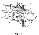
- Fig.1c shows the radial protrusions 110b in a turned and locked position.
- the pins 123 are shown within each of the aligned holes 122e and 122a. The pins are used during installation and are to be removed prior to operating the shaft.
- the features discussed herein eliminate the need for a typical ball and socket assembly within each coupling.
- the typically used ball and socket joints are wear items and need to be replaced after a defined number of service hours.
- the features discussed above greatly improve the Mean Time Between Maintenance Action (MTBMA) versus shafts using ball and socket assemblies.
- MTBMA Mean Time Between Maintenance Action
- the mechanism allowing the quill shaft 108 to be separable eliminates the restriction of prior art where the quill shaft length is based on the length of one flexible coupling.
Applications Claiming Priority (2)
| Application Number | Priority Date | Filing Date | Title |
|---|---|---|---|
| US16/403,229 US11408467B2 (en) | 2019-05-03 | 2019-05-03 | Flexible coupling assembly |
| EP19212068.1A EP3734100B1 (fr) | 2019-05-03 | 2019-11-28 | Ensemble de couplage flexible |
Related Parent Applications (1)
| Application Number | Title | Priority Date | Filing Date |
|---|---|---|---|
| EP19212068.1A Division EP3734100B1 (fr) | 2019-05-03 | 2019-11-28 | Ensemble de couplage flexible |
Publications (1)
| Publication Number | Publication Date |
|---|---|
| EP4095406A1 true EP4095406A1 (fr) | 2022-11-30 |
Family
ID=68731798
Family Applications (2)
| Application Number | Title | Priority Date | Filing Date |
|---|---|---|---|
| EP19212068.1A Active EP3734100B1 (fr) | 2019-05-03 | 2019-11-28 | Ensemble de couplage flexible |
| EP22181864.4A Pending EP4095406A1 (fr) | 2019-05-03 | 2019-11-28 | Ensemble couplage flexible |
Family Applications Before (1)
| Application Number | Title | Priority Date | Filing Date |
|---|---|---|---|
| EP19212068.1A Active EP3734100B1 (fr) | 2019-05-03 | 2019-11-28 | Ensemble de couplage flexible |
Country Status (2)
| Country | Link |
|---|---|
| US (2) | US11408467B2 (fr) |
| EP (2) | EP3734100B1 (fr) |
Families Citing this family (3)
| Publication number | Priority date | Publication date | Assignee | Title |
|---|---|---|---|---|
| US11408467B2 (en) * | 2019-05-03 | 2022-08-09 | Goodrich Corporation | Flexible coupling assembly |
| CN112901740A (zh) * | 2021-01-15 | 2021-06-04 | 杭州宇昌智慧科技有限公司 | 一种用于卷轴的柔性传动系统 |
| US11600506B2 (en) * | 2021-04-23 | 2023-03-07 | Taiwan Semiconductor Manufacturing Company Limited | Wafer pod transfer assembly |
Citations (4)
| Publication number | Priority date | Publication date | Assignee | Title |
|---|---|---|---|---|
| GB929323A (en) * | 1961-05-17 | 1963-06-19 | Ass Elect Ind | Improved flexible coupling particularly for turbine-generator equipment |
| US4265099A (en) * | 1979-03-02 | 1981-05-05 | General Electric Company | Flexible coupling |
| US5755622A (en) * | 1993-04-26 | 1998-05-26 | Mitsubish Jukogyo Kabushiki Kaisha | Centrifugally operated axial and torsional vibration reducer for a diaphragm coupling |
| EP3315807A1 (fr) * | 2016-10-27 | 2018-05-02 | Goodrich Corporation | Agencements de couplage redondants |
Family Cites Families (14)
| Publication number | Priority date | Publication date | Assignee | Title |
|---|---|---|---|---|
| GB191301201A (en) * | 1913-01-15 | 1914-01-15 | George Lunt | Improvements in Bakers' Ovens. |
| US1871227A (en) * | 1928-08-29 | 1932-08-09 | Cleveland Steel Products Corp | Flexible coupling |
| US2550580A (en) | 1945-01-16 | 1951-04-24 | Power Jets Res & Dev Ltd | Flexible coupling for shafts and the like |
| US2647380A (en) * | 1949-06-24 | 1953-08-04 | Bendix Aviat Corp | Flexible shaft |
| US2917910A (en) * | 1956-07-13 | 1959-12-22 | Thompson Ramo Wooldridge Inc | Coupling |
| GB1052336A (fr) * | 1962-02-09 | |||
| US4116018A (en) * | 1976-09-16 | 1978-09-26 | The Zeller Corporation | Universal joint |
| CH634133A5 (de) | 1979-02-16 | 1983-01-14 | Maag Zahnraeder & Maschinen Ag | Doppelgelenkkupplung. |
| SU846851A1 (ru) * | 1979-10-09 | 1981-07-15 | Хабаровский Ордена Трудового Красногознамени Дизелестроительный Завод"Дальдизель" | Упруга муфта |
| US5221232A (en) * | 1989-01-12 | 1993-06-22 | Zero-Max, Inc. | Flexible disc-like coupling element |
| US5158504A (en) | 1989-05-12 | 1992-10-27 | Lucas Aerospace Power Transmission Corp. | Flexible coupling including a flexible diaphragm element contoured with its thinnest thickness near the center thereof |
| US9546694B2 (en) | 2013-08-15 | 2017-01-17 | Goodrich Corporation | Flexible couplings for power transmission devices |
| US10704607B2 (en) | 2016-08-22 | 2020-07-07 | Goodrich Corporation | Flexible coupling arrangements for drive systems |
| US11408467B2 (en) * | 2019-05-03 | 2022-08-09 | Goodrich Corporation | Flexible coupling assembly |
-
2019
- 2019-05-03 US US16/403,229 patent/US11408467B2/en active Active
- 2019-11-28 EP EP19212068.1A patent/EP3734100B1/fr active Active
- 2019-11-28 EP EP22181864.4A patent/EP4095406A1/fr active Pending
-
2022
- 2022-03-29 US US17/707,553 patent/US20220221007A1/en active Pending
Patent Citations (4)
| Publication number | Priority date | Publication date | Assignee | Title |
|---|---|---|---|---|
| GB929323A (en) * | 1961-05-17 | 1963-06-19 | Ass Elect Ind | Improved flexible coupling particularly for turbine-generator equipment |
| US4265099A (en) * | 1979-03-02 | 1981-05-05 | General Electric Company | Flexible coupling |
| US5755622A (en) * | 1993-04-26 | 1998-05-26 | Mitsubish Jukogyo Kabushiki Kaisha | Centrifugally operated axial and torsional vibration reducer for a diaphragm coupling |
| EP3315807A1 (fr) * | 2016-10-27 | 2018-05-02 | Goodrich Corporation | Agencements de couplage redondants |
Also Published As
| Publication number | Publication date |
|---|---|
| EP3734100A1 (fr) | 2020-11-04 |
| US20220221007A1 (en) | 2022-07-14 |
| EP3734100B1 (fr) | 2022-07-20 |
| US20200347888A1 (en) | 2020-11-05 |
| US11408467B2 (en) | 2022-08-09 |
Similar Documents
| Publication | Publication Date | Title |
|---|---|---|
| US20220221007A1 (en) | Flexible coupling assembly | |
| US10180166B2 (en) | Disconnect mechanisms | |
| US2493232A (en) | Coupling | |
| US4134699A (en) | Coupling for shafts and the like | |
| EP0898661B1 (fr) | Boite d'engrenage anti-deplacement decalee vers l'arriere | |
| EP2837843B1 (fr) | Couplages souples pour dispositifs de transmission de puissance | |
| US5360376A (en) | Quick release disconnect coupling device for drive shaft segments | |
| US2550580A (en) | Flexible coupling for shafts and the like | |
| EP1197671B1 (fr) | Mécanisme de détente radiale pour couple d'embrayage à surcharge | |
| US10267367B2 (en) | Flexible coupling means, a mechanical transmission, and an aircraft | |
| US2892327A (en) | Flexible coupling | |
| US11713790B2 (en) | Torque limiter assembly | |
| US4701068A (en) | Spline anti-backlash device | |
| EP3486516A1 (fr) | Arbre rotatif souple avec accouplements à diaphragme pour des mouvements angulaires et axiaux | |
| US5409324A (en) | High strength, quick connect/disconnect coupling | |
| US5588917A (en) | Coupling with dual torque transmission paths | |
| US5672112A (en) | Zero clearance locking mechanism for a disconnect coupling device | |
| CZ83699A3 (cs) | Spojka pro přenos točivého momentu | |
| EP3315807B1 (fr) | Agencements de couplage redondants | |
| US20130146414A1 (en) | Drive Coupling Device | |
| US20180009524A1 (en) | Locking mechanisms for tail rotor drive disconnect couplings | |
| US6073742A (en) | Self-centering dog clutch | |
| US4311028A (en) | Flexible couplings | |
| US8776639B2 (en) | Spur gear power sharing gear sets | |
| WO2018156173A1 (fr) | Coupleur à connexion rapide pour transfert d'énergie de torsion |
Legal Events
| Date | Code | Title | Description |
|---|---|---|---|
| PUAI | Public reference made under article 153(3) epc to a published international application that has entered the european phase |
Free format text: ORIGINAL CODE: 0009012 |
|
| STAA | Information on the status of an ep patent application or granted ep patent |
Free format text: STATUS: THE APPLICATION HAS BEEN PUBLISHED |
|
| AC | Divisional application: reference to earlier application |
Ref document number: 3734100 Country of ref document: EP Kind code of ref document: P |
|
| AK | Designated contracting states |
Kind code of ref document: A1 Designated state(s): AL AT BE BG CH CY CZ DE DK EE ES FI FR GB GR HR HU IE IS IT LI LT LU LV MC MK MT NL NO PL PT RO RS SE SI SK SM TR |
|
| STAA | Information on the status of an ep patent application or granted ep patent |
Free format text: STATUS: REQUEST FOR EXAMINATION WAS MADE |
|
| 17P | Request for examination filed |
Effective date: 20230530 |
|
| RBV | Designated contracting states (corrected) |
Designated state(s): AL AT BE BG CH CY CZ DE DK EE ES FI FR GB GR HR HU IE IS IT LI LT LU LV MC MK MT NL NO PL PT RO RS SE SI SK SM TR |
|
| P01 | Opt-out of the competence of the unified patent court (upc) registered |
Effective date: 20230922 |