EP4095369B1 - Dual cycle intercooled hydrogen engine architecture - Google Patents
Dual cycle intercooled hydrogen engine architecture Download PDFInfo
- Publication number
- EP4095369B1 EP4095369B1 EP22175943.4A EP22175943A EP4095369B1 EP 4095369 B1 EP4095369 B1 EP 4095369B1 EP 22175943 A EP22175943 A EP 22175943A EP 4095369 B1 EP4095369 B1 EP 4095369B1
- Authority
- EP
- European Patent Office
- Prior art keywords
- hydrogen
- turbine
- gas
- heat exchanger
- compressor
- Prior art date
- Legal status (The legal status is an assumption and is not a legal conclusion. Google has not performed a legal analysis and makes no representation as to the accuracy of the status listed.)
- Active
Links
Images

Classifications
-
- F—MECHANICAL ENGINEERING; LIGHTING; HEATING; WEAPONS; BLASTING
- F02—COMBUSTION ENGINES; HOT-GAS OR COMBUSTION-PRODUCT ENGINE PLANTS
- F02C—GAS-TURBINE PLANTS; AIR INTAKES FOR JET-PROPULSION PLANTS; CONTROLLING FUEL SUPPLY IN AIR-BREATHING JET-PROPULSION PLANTS
- F02C7/00—Features, components parts, details or accessories, not provided for in, or of interest apart form groups F02C1/00 - F02C6/00; Air intakes for jet-propulsion plants
- F02C7/12—Cooling of plants
- F02C7/14—Cooling of plants of fluids in the plant, e.g. lubricant or fuel
- F02C7/141—Cooling of plants of fluids in the plant, e.g. lubricant or fuel of working fluid
- F02C7/143—Cooling of plants of fluids in the plant, e.g. lubricant or fuel of working fluid before or between the compressor stages
-
- F—MECHANICAL ENGINEERING; LIGHTING; HEATING; WEAPONS; BLASTING
- F02—COMBUSTION ENGINES; HOT-GAS OR COMBUSTION-PRODUCT ENGINE PLANTS
- F02C—GAS-TURBINE PLANTS; AIR INTAKES FOR JET-PROPULSION PLANTS; CONTROLLING FUEL SUPPLY IN AIR-BREATHING JET-PROPULSION PLANTS
- F02C3/00—Gas-turbine plants characterised by the use of combustion products as the working fluid
- F02C3/20—Gas-turbine plants characterised by the use of combustion products as the working fluid using a special fuel, oxidant, or dilution fluid to generate the combustion products
- F02C3/22—Gas-turbine plants characterised by the use of combustion products as the working fluid using a special fuel, oxidant, or dilution fluid to generate the combustion products the fuel or oxidant being gaseous at standard temperature and pressure
-
- F—MECHANICAL ENGINEERING; LIGHTING; HEATING; WEAPONS; BLASTING
- F02—COMBUSTION ENGINES; HOT-GAS OR COMBUSTION-PRODUCT ENGINE PLANTS
- F02C—GAS-TURBINE PLANTS; AIR INTAKES FOR JET-PROPULSION PLANTS; CONTROLLING FUEL SUPPLY IN AIR-BREATHING JET-PROPULSION PLANTS
- F02C3/00—Gas-turbine plants characterised by the use of combustion products as the working fluid
- F02C3/20—Gas-turbine plants characterised by the use of combustion products as the working fluid using a special fuel, oxidant, or dilution fluid to generate the combustion products
-
- F—MECHANICAL ENGINEERING; LIGHTING; HEATING; WEAPONS; BLASTING
- F02—COMBUSTION ENGINES; HOT-GAS OR COMBUSTION-PRODUCT ENGINE PLANTS
- F02C—GAS-TURBINE PLANTS; AIR INTAKES FOR JET-PROPULSION PLANTS; CONTROLLING FUEL SUPPLY IN AIR-BREATHING JET-PROPULSION PLANTS
- F02C7/00—Features, components parts, details or accessories, not provided for in, or of interest apart form groups F02C1/00 - F02C6/00; Air intakes for jet-propulsion plants
- F02C7/12—Cooling of plants
- F02C7/16—Cooling of plants characterised by cooling medium
- F02C7/18—Cooling of plants characterised by cooling medium the medium being gaseous, e.g. air
-
- F—MECHANICAL ENGINEERING; LIGHTING; HEATING; WEAPONS; BLASTING
- F02—COMBUSTION ENGINES; HOT-GAS OR COMBUSTION-PRODUCT ENGINE PLANTS
- F02C—GAS-TURBINE PLANTS; AIR INTAKES FOR JET-PROPULSION PLANTS; CONTROLLING FUEL SUPPLY IN AIR-BREATHING JET-PROPULSION PLANTS
- F02C7/00—Features, components parts, details or accessories, not provided for in, or of interest apart form groups F02C1/00 - F02C6/00; Air intakes for jet-propulsion plants
- F02C7/22—Fuel supply systems
- F02C7/224—Heating fuel before feeding to the burner
-
- F—MECHANICAL ENGINEERING; LIGHTING; HEATING; WEAPONS; BLASTING
- F02—COMBUSTION ENGINES; HOT-GAS OR COMBUSTION-PRODUCT ENGINE PLANTS
- F02C—GAS-TURBINE PLANTS; AIR INTAKES FOR JET-PROPULSION PLANTS; CONTROLLING FUEL SUPPLY IN AIR-BREATHING JET-PROPULSION PLANTS
- F02C7/00—Features, components parts, details or accessories, not provided for in, or of interest apart form groups F02C1/00 - F02C6/00; Air intakes for jet-propulsion plants
- F02C7/36—Power transmission arrangements between the different shafts of the gas turbine plant, or between the gas-turbine plant and the power user
-
- F—MECHANICAL ENGINEERING; LIGHTING; HEATING; WEAPONS; BLASTING
- F02—COMBUSTION ENGINES; HOT-GAS OR COMBUSTION-PRODUCT ENGINE PLANTS
- F02C—GAS-TURBINE PLANTS; AIR INTAKES FOR JET-PROPULSION PLANTS; CONTROLLING FUEL SUPPLY IN AIR-BREATHING JET-PROPULSION PLANTS
- F02C9/00—Controlling gas-turbine plants; Controlling fuel supply in air- breathing jet-propulsion plants
- F02C9/26—Control of fuel supply
- F02C9/263—Control of fuel supply by means of fuel metering valves
-
- F—MECHANICAL ENGINEERING; LIGHTING; HEATING; WEAPONS; BLASTING
- F02—COMBUSTION ENGINES; HOT-GAS OR COMBUSTION-PRODUCT ENGINE PLANTS
- F02C—GAS-TURBINE PLANTS; AIR INTAKES FOR JET-PROPULSION PLANTS; CONTROLLING FUEL SUPPLY IN AIR-BREATHING JET-PROPULSION PLANTS
- F02C3/00—Gas-turbine plants characterised by the use of combustion products as the working fluid
- F02C3/04—Gas-turbine plants characterised by the use of combustion products as the working fluid having a turbine driving a compressor
-
- F—MECHANICAL ENGINEERING; LIGHTING; HEATING; WEAPONS; BLASTING
- F02—COMBUSTION ENGINES; HOT-GAS OR COMBUSTION-PRODUCT ENGINE PLANTS
- F02C—GAS-TURBINE PLANTS; AIR INTAKES FOR JET-PROPULSION PLANTS; CONTROLLING FUEL SUPPLY IN AIR-BREATHING JET-PROPULSION PLANTS
- F02C7/00—Features, components parts, details or accessories, not provided for in, or of interest apart form groups F02C1/00 - F02C6/00; Air intakes for jet-propulsion plants
- F02C7/32—Arrangement, mounting, or driving, of auxiliaries
-
- F—MECHANICAL ENGINEERING; LIGHTING; HEATING; WEAPONS; BLASTING
- F05—INDEXING SCHEMES RELATING TO ENGINES OR PUMPS IN VARIOUS SUBCLASSES OF CLASSES F01-F04
- F05D—INDEXING SCHEME FOR ASPECTS RELATING TO NON-POSITIVE-DISPLACEMENT MACHINES OR ENGINES, GAS-TURBINES OR JET-PROPULSION PLANTS
- F05D2260/00—Function
- F05D2260/20—Heat transfer, e.g. cooling
- F05D2260/211—Heat transfer, e.g. cooling by intercooling, e.g. during a compression cycle
-
- F—MECHANICAL ENGINEERING; LIGHTING; HEATING; WEAPONS; BLASTING
- F05—INDEXING SCHEMES RELATING TO ENGINES OR PUMPS IN VARIOUS SUBCLASSES OF CLASSES F01-F04
- F05D—INDEXING SCHEME FOR ASPECTS RELATING TO NON-POSITIVE-DISPLACEMENT MACHINES OR ENGINES, GAS-TURBINES OR JET-PROPULSION PLANTS
- F05D2260/00—Function
- F05D2260/20—Heat transfer, e.g. cooling
- F05D2260/213—Heat transfer, e.g. cooling by the provision of a heat exchanger within the cooling circuit
Definitions
- US 2020/088099 discloses a hybrid expander cycle with a turbo-generator and cooled power electronics.
- a controller is operatively connected to the gaseous hydrogen meter and at least one sensor in any of the gearbox, the hydrogen expansion turbine, and/or the turbine section,
- the controller can include machine readable instructions that cause the controller to receive input for a command power, receive input from at least one of the gearbox, the hydrogen expansion turbine, and/or the turbine section, adjust the flow of gaseous hydrogen via the gaseous hydrogen meter to achieve the command power.
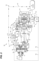
- Fig. 1 a partial view of an embodiment of a system in accordance with the disclosure is shown in Fig. 1 and is designated generally by reference character 100.
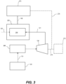
- Fig. 2 Other embodiments and/or aspects of this disclosure are shown in Fig. 2 .
- the systems and methods described herein can be used to improve engine efficiency, reduce carbon emissions, and improve power to weight ratio.
- the primary gas path 106 includes, in fluid series communication: an air inlet 112, the compressor 104 fluidly connected to the air inlet 112, the combustor 108 fluidly connected to an outlet 114 of the compressor 104, and a turbine section 116 fluidly connected to an outlet 118 of the combustor 108, the turbine section 116 operatively connected to the compressor 104 to drive the compressor 104.
- a main output shaft 120 is operatively connected to the turbine section 116 to be driven by the turbine section 116.
- a heat exchanger 122 is fluidly connected between a liquid hydrogen supply 124 and the compressor 104.
- a gas conduit 126 is fluidly connected to the primary gas path 106, and a fluid conduit 128, carrying liquid hydrogen from the liquid hydrogen supply 124, in thermal communication with the gas conduit 126, but is fluidly isolated from the gas conduit 126, fluidly connects the liquid hydrogen supply 124 to the primary gas path 106.
- the compressor 104 includes a first stage (e.g. low pressure) compressor 140 and a second stage (e.g. high pressure) compressor 142.
- the second stage compressor 142 is in fluid communication with the first stage compressor 140 through an inter-stage duct 144.
- the heat exchanger 122 is fluidly connected to the primary gas path 106 between the adjacent first and second stage compressors 140, 142 such that the inter-stage duct 144 forms a compressor air conduit through the heat exchanger 122.
- hot compressed air from the first stage compressor 140 passes through conduit 126 to the second stage compressor 142, where heat is exchanged in the heat exchanger 122 so that liquid hydrogen in the fluid conduit 128 is evaporated to gaseous hydrogen.
- the expansion turbine 134 is operatively connected to the main shaft 120 (e.g. via the gearbox 148 and output shaft 151) to drive the main shaft 120 in parallel with the turbine section 116. In this manner, the main shaft 120 is driven by combined power from the turbine section 116 and the expansion turbine 134.
- the hydrogen expansion turbine 134 can be operatively connected to one or both of an electrical power generator 152 to drive the electrical power generator 152, and an auxiliary air compressor 154 to drive the auxiliary air compressor 154.
- a gaseous hydrogen accumulator 156 is disposed in conduit 139 downstream of the heat exchanger 122 relative to hydrogen flow, wherein the gaseous hydrogen accumulator 156 is between the heat exchanger 122 and the combustor 108.
- a gaseous hydrogen meter 158 is disposed in the conduit 139 downstream of the gaseous hydrogen accumulator 156 relative to hydrogen flow for controlling flow of hydrogen to the combustor 108, the gaseous hydrogen meter 158 being between the accumulator 156 and the combustor 108.
- the expanded low pressure gaseous hydrogen 121 is collected and stored in the gaseous hydrogen accumulator 156 and then regulated to a pressure where it can then be metered (e.g. via meter 158) to provide combustor ready hydrogen gas to the combustor 108.
- a controller 160 is operatively connected to the gaseous hydrogen meter 158 and at least one sensor included in any of the gearbox 148, the hydrogen expansion turbine 134, and/or the turbine section 116.
- the controller 160 can include machine readable instructions that cause the controller to receive input 145 for a command power, receive input 147 from at least one of the gearbox 148, the hydrogen expansion turbine 134, and/or the turbine section 136, and adjust the flow of gaseous hydrogen 121 via the gaseous hydrogen meter 158 to achieve the command power, based on the input (e.g. signals 161, 162, 163, 164) received by the controller 160.
- the controller 160 can additionally receive input from a compressor pressure (e.g. P3 pressure, upstream of the accumulator 156) and input from the accumulator 156 downstream of the compressor pressure.
- the controller 160 can include machine readable instruction operable to execute the method.
- the method includes, supplying liquid hydrogen 119 to a heat exchanger 122 and expanding the liquid hydrogen 119 to gaseous hydrogen 121 with heat supplied to the heat exchanger 122, supplying the heat to the heat exchanger 122 with compressed air from a first stage compressor 140, where expanding the liquid hydrogen 119 to gaseous hydrogen 121 includes cooling the compressed air from the first stage compressor 140, compressing cooled air from the heat exchanger 122, and combusting the gaseous hydrogen 121 with the compressed cooled air in the combustor 108.
- the method includes extracting power from a flow of gaseous hydrogen 121 with a hydrogen expansion turbine 134 downstream of the heat exchanger 122. In certain embodiments, the method includes combining power from the expansion turbine 134 with power from a main shaft 120 driven by a turbine section 116 to drive an output shaft 151 for example to generate thrust and/or electrical power. In certain embodiments, the method includes receiving input from at least one of the gearbox 148, the hydrogen expansion turbine 134, and/or the turbine section 116 (e.g. signals 161, 162, 163, 164) and outputting a command 165 to the gaseous hydrogen meter 158 to adjust flow of gaseous hydrogen 121 to the combustor 108 to achieve a command power output at the output shaft 151.
- the gearbox 148 the hydrogen expansion turbine 134
- the turbine section 116 e.g. signals 161, 162, 163, 164
- a dual cycle intercooled architecture as described herein can be retrofit on an existing, conventional gas turbine engine.
- any or all of a liquid hydrogen supply 124, heat exchanger 122, a gaseous hydrogen accumulator 156, a gaseous hydrogen meter 158, an expansion turbine 134 between the heat exchanger 122 and the gaseous hydrogen accumulator 156 can be introduced in an existing turbine engine.
- the system can then be connected as follows: connecting the liquid hydrogen supply 124 to the heat exchanger 122 via a liquid hydrogen pump 133 in a first line (e.g. fluid conduit 128), connecting the heat exchanger 122 to the expansion turbine 134 via a second line (e.g.
- conduit 139 an upstream portion of conduit 139
- conduit 139 connecting the expansion turbine 134 to the combustor via a third line (e.g. a downstream portion of conduit 139), wherein the gaseous hydrogen accumulator 156 and gaseous hydrogen meter 158 are disposed in the third line.
- the liquid hydrogen tank 131 is fluidly connected to the liquid hydrogen supply 124 for supplying hydrogen to a hydrogen conversion module 266.
- the hydrogen conversion module 266 can be included within the engine 200, for combustion of hydrogen within the combustor 108.
- the hydrogen conversion module 266 is fluidly connected to the inlet 136 of the expansion turbine 134 for driving the expansion turbine 134.
- the hydrogen conversion module 266 can includes all of heat exchanger 122, liquid H2 pump 133, accumulator 156, and a meter 158.
- the hydrogen conversion module 266 can be any suitable different combination of elements interconnected to be operable to provide a supply of gaseous hydrogen, for example a combination that is suitable to the particular engine with which the hydrogen conversion module 266 is used.
- a hydrogen combustion module 268 can be fluidly connected to the outlet 138 of the expansion turbine 134 and operatively connected to the output shaft 151, for converting thermal energy into rotational energy to drive the output shaft 151.
- the engine 200 is operatively connected to a driven component 270 via the output shaft 151.
- the driven component 270 is driven by the output shaft 151 of the engine 200 and can be a rotor, for example, or any one of, or any combination of a propeller, a fan, a compressor, a gearbox, an electric generator, or the like.
- the expansion turbine 134 can optionally be operatively connected to another driven component 272 for driving the driven component 272 in series with driven component 270 via shaft 274.
- the driven component 272 can be the same or different than driven component 270. It is also contemplated that the driven component 270 can be optionally operatively connected to driven component 272 via shaft 276 for driving driven component 272 in parallel with driven component 270.
- This architecture differs from other intercooled or expansion turbine engines in that it combines several engine improvements by making use of cold liquid hydrogen for cooling and expansion.
- the methods and systems of the present disclosure as described above and shown in the drawings, provide for improved engine efficiency through intercooling. Additionally, inclusion of the expansion turbine allows for a smaller engine without sacrificing power output, therefore improving power to weight ratio. Carbon emissions may also be reduced or eliminated. Finally, this arrangement accomplishes these improvements in a compact package which would fit in existing nacelle loft lines (e.g. for a turboprop) therefore minimizing drag.
Landscapes
- Engineering & Computer Science (AREA)
- Chemical & Material Sciences (AREA)
- Combustion & Propulsion (AREA)
- Mechanical Engineering (AREA)
- General Engineering & Computer Science (AREA)
- Engine Equipment That Uses Special Cycles (AREA)
- Heat-Exchange Devices With Radiators And Conduit Assemblies (AREA)
Description
- The present disclosure relates generally to gas turbine engines, and more particularly to gas turbine engines with intercooling. There is always a need in the art for improvements to engine architecture in the aerospace industry.
-
US 2020/088099 discloses a hybrid expander cycle with a turbo-generator and cooled power electronics. -
US 2020/088102 discloses a hybrid expander cycle with intercooling and a turbo-generator. -
US 2016/123226 discloses a gas turbine using a cryogenic fuel and extracting work therefrom - According to an aspect of the present invention, there is provided a gas turbine engine in accordance with
claim 1. - In certain embodiments, the gas turbine engine includes an expansion turbine having a gas inlet fluidly connected to the gaseous hydrogen outlet and a gas outlet fluidly connected to the gas inlet, the gas outlet of the expansion turbine being fluidly connected to the combustor.
- In certain embodiments, a liquid hydrogen pump is fluidly connected to the liquid hydrogen inlet of the heat exchanger and operable to supply liquid hydrogen to the liquid hydrogen inlet of the heat exchanger. In certain embodiments, the expansion turbine is operatively connected to the output shaft to drive the output shaft in parallel with the turbine section. In certain embodiments, the gas turbine engine includes a gearbox, where the gear box is operatively connected to a main shaft driven by a turbine section of the gas turbine engine. The gearbox can further include an output shaft driven by combined power from the turbine section and the expansion turbine. In certain embodiments, an outlet of the hydrogen expansion turbine is in fluid communication with the combustor to provide combustor ready hydrogen gas to the combustor and to add additional rotational power to the gearbox.
- In certain embodiments, the expansion turbine is operatively connected to one or both of: an electrical power generator to drive the electrical power generator, and an auxiliary air compressor to drive the auxiliary air compressor.
- In certain embodiments, a controller is operatively connected to the gaseous hydrogen meter and at least one sensor in any of the gearbox, the hydrogen expansion turbine, and/or the turbine section, The controller can include machine readable instructions that cause the controller to receive input for a command power, receive input from at least one of the gearbox, the hydrogen expansion turbine, and/or the turbine section, adjust the flow of gaseous hydrogen via the gaseous hydrogen meter to achieve the command power.
- According to another aspect of the present invention, there is provided a method of retrofitting a gas turbine engine with a dual cycle intercooled architecture in accordance with claim 9.
- These and other features of the systems and methods of the subject disclosure will become more readily apparent to those skilled in the art from the following detailed description taken in conjunction with the drawings.
- So that those skilled in the art to which the subject disclosure appertains will readily understand how to make and use the devices and methods of the subject disclosure without undue experimentation, embodiments thereof will be described in detail herein below with reference to certain figures, wherein:
-
Fig. 1 is a schematic view of an embodiment of an aircraft in accordance with this disclosure; -
Fig. 2 is a schematic diagram of an embodiment of a gas turbine engine constructed in accordance with the present disclosure, showing a dual cycle intercooled engine architecture; and -
Fig. 3 is a schematic diagram of another embodiment of a gas turbine engine constructed in accordance with the present disclosure, showing another dual cycle intercooled engine architecture. - Reference will now be made to the drawings wherein like reference numerals identify similar structural features or aspects of the subject disclosure. For purposes of explanation and illustration, and not limitation, a partial view of an embodiment of a system in accordance with the disclosure is shown in
Fig. 1 and is designated generally byreference character 100. Other embodiments and/or aspects of this disclosure are shown inFig. 2 . The systems and methods described herein can be used to improve engine efficiency, reduce carbon emissions, and improve power to weight ratio. - Traditionally, hydrocarbon fuels are used to power gas turbine engines, however, it is possible to use a variety of fuels for the combustion portion of the Brayton Cycle, for example pure hydrogen, non-hydrocarbon fuels, or mixes. When hydrogen is used as the fuel, it is possible to operate the gas turbine engine with little or no pollutants in the exhaust. Moreover, various means of intercooling/evaporating are also possible when using hydrogen fuel, as described and contemplated herein. As a non-limiting example, such means of intercooling/evaporating may include in-situ pre-coolers in the engine inlet or axial intercoolers between axial compressors.
- In certain embodiments, referring to
Fig. 1 , anaircraft 1 can include anengine 100, where the engine can be a propulsive energy engine (e.g. creating thrust for the aircraft 1), or a non-propulsive energy engine, and afuel system 100. As described herein, theengine 100 is a turbofan engine, although the present technology may likewise be used with other engine types. Theengine 100 includes acompressor section 102 having acompressor 104 in aprimary gas path 106 to supply compressed air to acombustor 108 of theaircraft engine 100, theprimary gas path 106 including fluidly in series thecombustor 108 and nozzle manifold 110 for issuing fluid to thecombustor 108. - More specifically the
primary gas path 106 includes, in fluid series communication: anair inlet 112, thecompressor 104 fluidly connected to theair inlet 112, thecombustor 108 fluidly connected to anoutlet 114 of thecompressor 104, and aturbine section 116 fluidly connected to anoutlet 118 of thecombustor 108, theturbine section 116 operatively connected to thecompressor 104 to drive thecompressor 104. - A
main output shaft 120 is operatively connected to theturbine section 116 to be driven by theturbine section 116. Aheat exchanger 122 is fluidly connected between aliquid hydrogen supply 124 and thecompressor 104. Agas conduit 126 is fluidly connected to theprimary gas path 106, and afluid conduit 128, carrying liquid hydrogen from theliquid hydrogen supply 124, in thermal communication with thegas conduit 126, but is fluidly isolated from thegas conduit 126, fluidly connects theliquid hydrogen supply 124 to theprimary gas path 106. - The
fluid conduit 128 has aliquid hydrogen inlet 130 and agaseous hydrogen outlet 132 fluidly connected to theliquid hydrogen inlet 130. Aliquid hydrogen pump 133 is fluidly connected to theliquid hydrogen inlet 130 of theheat exchanger 122 and operable to supply liquid hydrogen to theliquid hydrogen inlet 130. It is contemplated that any suitable liquid hydrogen supply can be used, for example, the liquid hydrogen can be pumped from aircraftcryogenic tanks 131 using theliquid hydrogen pump 133 mounted on an accessory pad (e.g. on an engine accessory gearbox), or thepump 133 may be driven externally by other means. - An
expansion turbine 134 having agas inlet 136 is fluidly connected to thegaseous hydrogen outlet 132 and agas outlet 138 fluidly connected to thegas inlet 136, where thegas outlet 138 of theexpansion turbine 134 is fluidly connected to thecombustor 108 viaconduit 139. - In certain embodiments, the
compressor 104 includes a first stage (e.g. low pressure)compressor 140 and a second stage (e.g. high pressure)compressor 142. Thesecond stage compressor 142 is in fluid communication with thefirst stage compressor 140 through aninter-stage duct 144. Theheat exchanger 122 is fluidly connected to theprimary gas path 106 between the adjacent first andsecond stage compressors inter-stage duct 144 forms a compressor air conduit through theheat exchanger 122. For example, hot compressed air from thefirst stage compressor 140 passes throughconduit 126 to thesecond stage compressor 142, where heat is exchanged in theheat exchanger 122 so that liquid hydrogen in thefluid conduit 128 is evaporated to gaseous hydrogen. This heat exchange serves the dual purpose of converting theliquid hydrogen 119 togaseous hydrogen 121 to be used as fuel in thecombustor 108, and while also cooling theair inlet 112 of thecompressor 104, improving engine efficiency. The hydrogen (119, 121) and compressor air are in fluid isolation from each other throughout their respective passages (conduits 126, 138) in theheat exchanger 122 to avoid mixing of air and hydrogen in theheat exchanger 122, but are in thermal communication with one another for heat exchange between the hydrogen and compressor air in theheat exchanger 122. - The
hydrogen expansion turbine 134 is positioned downstream of theheat exchanger 122 and upstream of thecombustor 108 relative to hydrogen flow (119, 121). A rotatable element of the expansion turbine 134 (e.g. a turbine shaft 146) is operatively connected to a gearbox 148 (e.g. a reduction gearbox for a propeller, accessory gearbox, or the like) to input additional rotational power to thegearbox 128. More specifically, theexpansion turbine shaft 146 is meshed with at least onegear 150 in thegearbox 148 such that when theliquid hydrogen 119 is converted to agaseous state 121, the power from the expanding gas is extracted through theexpansion turbine 134, driving theexpansion turbine 134, adding additional rotational power to thegearbox 148. For example, theexpansion turbine 134 is operatively connected to the main shaft 120 (e.g. via thegearbox 148 and output shaft 151) to drive themain shaft 120 in parallel with theturbine section 116. In this manner, themain shaft 120 is driven by combined power from theturbine section 116 and theexpansion turbine 134. In certain embodiments, thehydrogen expansion turbine 134 can be operatively connected to one or both of an electrical power generator 152 to drive the electrical power generator 152, and an auxiliary air compressor 154 to drive the auxiliary air compressor 154. - A
gaseous hydrogen accumulator 156 is disposed inconduit 139 downstream of theheat exchanger 122 relative to hydrogen flow, wherein thegaseous hydrogen accumulator 156 is between theheat exchanger 122 and thecombustor 108. Agaseous hydrogen meter 158 is disposed in theconduit 139 downstream of thegaseous hydrogen accumulator 156 relative to hydrogen flow for controlling flow of hydrogen to thecombustor 108, thegaseous hydrogen meter 158 being between theaccumulator 156 and thecombustor 108. After thegaseous hydrogen 121 is evaporated and extracted through theexpansion turbine 134, the expanded low pressuregaseous hydrogen 121 is collected and stored in thegaseous hydrogen accumulator 156 and then regulated to a pressure where it can then be metered (e.g. via meter 158) to provide combustor ready hydrogen gas to thecombustor 108. - In certain embodiments, a
controller 160 is operatively connected to thegaseous hydrogen meter 158 and at least one sensor included in any of thegearbox 148, thehydrogen expansion turbine 134, and/or theturbine section 116. Thecontroller 160 can include machine readable instructions that cause the controller to receive input 145 for a command power, receive input 147 from at least one of thegearbox 148, thehydrogen expansion turbine 134, and/or theturbine section 136, and adjust the flow ofgaseous hydrogen 121 via thegaseous hydrogen meter 158 to achieve the command power, based on the input (e.g. signals controller 160. In embodiments, thecontroller 160 can additionally receive input from a compressor pressure (e.g. P3 pressure, upstream of the accumulator 156) and input from theaccumulator 156 downstream of the compressor pressure. - In yet another aspect of the present disclosure, there is provided a method, which is not part of the claimed subject-matter. For example, the
controller 160 can include machine readable instruction operable to execute the method. The method includes, supplyingliquid hydrogen 119 to aheat exchanger 122 and expanding theliquid hydrogen 119 togaseous hydrogen 121 with heat supplied to theheat exchanger 122, supplying the heat to theheat exchanger 122 with compressed air from afirst stage compressor 140, where expanding theliquid hydrogen 119 togaseous hydrogen 121 includes cooling the compressed air from thefirst stage compressor 140, compressing cooled air from theheat exchanger 122, and combusting thegaseous hydrogen 121 with the compressed cooled air in thecombustor 108. - In embodiments, the method includes extracting power from a flow of
gaseous hydrogen 121 with ahydrogen expansion turbine 134 downstream of theheat exchanger 122. In certain embodiments, the method includes combining power from theexpansion turbine 134 with power from amain shaft 120 driven by aturbine section 116 to drive anoutput shaft 151 for example to generate thrust and/or electrical power. In certain embodiments, the method includes receiving input from at least one of thegearbox 148, thehydrogen expansion turbine 134, and/or the turbine section 116 (e.g. signals 161, 162, 163, 164) and outputting acommand 165 to thegaseous hydrogen meter 158 to adjust flow ofgaseous hydrogen 121 to thecombustor 108 to achieve a command power output at theoutput shaft 151. - It is contemplated that a dual cycle intercooled architecture as described herein can be retrofit on an existing, conventional gas turbine engine. For example, any or all of a
liquid hydrogen supply 124,heat exchanger 122, agaseous hydrogen accumulator 156, agaseous hydrogen meter 158, anexpansion turbine 134 between theheat exchanger 122 and thegaseous hydrogen accumulator 156, can be introduced in an existing turbine engine. The system can then be connected as follows: connecting theliquid hydrogen supply 124 to theheat exchanger 122 via aliquid hydrogen pump 133 in a first line (e.g. fluid conduit 128), connecting theheat exchanger 122 to theexpansion turbine 134 via a second line (e.g. an upstream portion of conduit 139), and connecting theexpansion turbine 134 to the combustor via a third line (e.g. a downstream portion of conduit 139), wherein thegaseous hydrogen accumulator 156 andgaseous hydrogen meter 158 are disposed in the third line. - In certain embodiments, for example as provided in
Fig. 3 , anengine 200 can be similarly retrofit with similar architecture as ingas turbine engine 100. For brevity, the description of common elements that have been described above are not repeated. Theengine 200 can be a hydrogen poweredaircraft engine 200, for example theengine 200 can be a heat engine, a gas turbine engine, a reciprocating heat engine, a rotary heat engine, or the like. Theengine 200 can be fed by primary gas path 106 (e.g. an air supply) andgaseous hydrogen 121. - The
liquid hydrogen tank 131 is fluidly connected to theliquid hydrogen supply 124 for supplying hydrogen to ahydrogen conversion module 266. - The
hydrogen conversion module 266 can be included within theengine 200, for combustion of hydrogen within thecombustor 108. Thehydrogen conversion module 266 is fluidly connected to theinlet 136 of theexpansion turbine 134 for driving theexpansion turbine 134. In certain embodiments, thehydrogen conversion module 266 can includes all ofheat exchanger 122,liquid H2 pump 133,accumulator 156, and ameter 158. However, it is contemplated that thehydrogen conversion module 266 can be any suitable different combination of elements interconnected to be operable to provide a supply of gaseous hydrogen, for example a combination that is suitable to the particular engine with which thehydrogen conversion module 266 is used. - A
hydrogen combustion module 268 can be fluidly connected to theoutlet 138 of theexpansion turbine 134 and operatively connected to theoutput shaft 151, for converting thermal energy into rotational energy to drive theoutput shaft 151. Theengine 200 is operatively connected to a drivencomponent 270 via theoutput shaft 151. The drivencomponent 270 is driven by theoutput shaft 151 of theengine 200 and can be a rotor, for example, or any one of, or any combination of a propeller, a fan, a compressor, a gearbox, an electric generator, or the like. In certain embodiments, theexpansion turbine 134 can optionally be operatively connected to another drivencomponent 272 for driving the drivencomponent 272 in series with drivencomponent 270 viashaft 274. It is contemplated that the drivencomponent 272 can be the same or different than drivencomponent 270. It is also contemplated that the drivencomponent 270 can be optionally operatively connected to drivencomponent 272 viashaft 276 for driving drivencomponent 272 in parallel withdriven component 270. - With this method, the power generated by burning the hydrogen and then extracting the power through a power turbine is compounded by the power extracted by the expansion turbine and then combined through the gearbox. This architecture allows dual cycles of expansion and combustion of hydrogen with intercooling to be packaged within an existing turboprop nacelle loft, for example.
- This architecture differs from other intercooled or expansion turbine engines in that it combines several engine improvements by making use of cold liquid hydrogen for cooling and expansion. The methods and systems of the present disclosure, as described above and shown in the drawings, provide for improved engine efficiency through intercooling. Additionally, inclusion of the expansion turbine allows for a smaller engine without sacrificing power output, therefore improving power to weight ratio. Carbon emissions may also be reduced or eliminated. Finally, this arrangement accomplishes these improvements in a compact package which would fit in existing nacelle loft lines (e.g. for a turboprop) therefore minimizing drag.
- While the apparatus and methods of the subject disclosure have been shown and described, those skilled in the art will readily appreciate that changes and/or modifications may be made thereto without departing from the scope of the subject disclosure.
Claims (10)
- A gas turbine engine (100), comprising:a primary gas path (106) having, in fluid series communication: an air inlet (112), a compressor (104) fluidly connected to the air inlet (112), a combustor (108) fluidly connected to an outlet of the compressor (104), and a turbine section (116) fluidly connected to an outlet of the combustor section (108), the turbine section (116) operatively connected to the compressor (104) to drive the compressor (104);an output shaft (151) operatively connected to the turbine section (116) to be driven by the turbine section (116);a heat exchanger (122) having:a gas conduit (126) fluidly connected to the primary gas path (106); anda fluid conduit (128) in fluid isolation from the gas conduit (126) and in thermal communication with the gas conduit (126), the fluid conduit (128) having a liquid hydrogen inlet (130) and a gaseous hydrogen outlet (132) fluidly connected to the liquid hydrogen inlet (130); andan expansion turbine (134) having a gas inlet (136) fluidly connected to the gaseous hydrogen outlet (132) and a gas outlet (138) fluidly connected to the gas inlet (136), the gas outlet (138) of the expansion turbine (134) being fluidly connected to the combustor (108), characterised in that:the compressor (104) has multiple compressor sections and the gas conduit (126) of the heat exchanger (122) is fluidly connected to the primary gas path (106) at a location between adjacent compressor sections of the multiple compressor sections; andthe gas turbine engine (100) further comprises:a gaseous hydrogen accumulator (156) downstream of the heat exchanger (122) relative to hydrogen flow, wherein the gaseous hydrogen accumulator (156) is between the heat exchanger (122) and the combustor (108); anda gaseous hydrogen meter (158) downstream of the gaseous hydrogen accumulator (156) relative to hydrogen flow for controlling flow of hydrogen to the combustor (108), wherein the gaseous hydrogen meter (158) is between the accumulator (156) and the combustor (108), wherein the expansion turbine (134) is a hydrogen expansion turbine (134) downstream of the heat exchanger (122) and upstream of the combustor (108) relative to hydrogen flow, and a turbine shaft (146) of the hydrogen expansion turbine (134) is operatively connected to a gearbox (148).
- The gas turbine engine (100) of claim 1, further comprising a liquid hydrogen pump (133) fluidly connected to the liquid hydrogen inlet (130) of the heat exchanger (122) and operable to supply liquid hydrogen (119) to the liquid hydrogen inlet (130) of the heat exchanger (122).
- The gas turbine engine (100) of claim 1 or 2, wherein the expansion turbine (134) is operatively connected to the output shaft (151) to drive the output shaft (151) in parallel with the turbine section (116).
- The gas turbine engine (100) of claim 3, wherein the gearbox (148) is operatively connected to a main shaft (120) driven by a turbine section (116) of the gas turbine engine (100), wherein the gearbox (148) further includes the output shaft (151) driven by combined power from the turbine section (116) and the expansion turbine (134).
- The gas turbine engine (100) of any preceding claim, wherein the expansion turbine (134) is operatively connected to an electrical power generator (152) to drive the electrical power generator (152).
- The gas turbine engine (100) of any preceding claim, wherein the expansion turbine (134) is operatively connected to an auxiliary air compressor (154) to drive the auxiliary air compressor (154).
- The gas turbine engine (100) of any preceding claim, wherein an outlet of the hydrogen expansion turbine (134) is in fluid communication with the combustor (108) to provide combustor ready hydrogen gas to the combustor (108) and to add additional rotational power the gearbox (148), the gearbox (148) is operatively connected to a main shaft (120) driven by the turbine section (116) of the gas turbine engine (100), and the gearbox (148) further includes the output shaft (151) driven by combined power from the turbine section (116) and the expansion turbine (134).
- The gas turbine engine (100) of claim 7, further comprising a controller (160) operatively connected to the gaseous hydrogen meter (158) and at least one sensor in the gearbox (148), the hydrogen expansion turbine (134), and/or the turbine section (116), wherein the controller (160) includes machine readable instructions that cause the controller (160) to:receive input (145) for a command (165) power;receive input (147) from the gearbox (148), the hydrogen expansion turbine (134), and/or the turbine section (116); andadjust the flow of gaseous hydrogen (121) via the gaseous hydrogen meter (158) to achieve the command power.
- A method of retrofitting a gas turbine engine (100) with a dual cycle intercooled architecture, the method comprising:introducing a liquid hydrogen supply (124);introducing a heat exchanger (122) to a duct between the first stage compressor (140) and the second stage compressor (142);introducing a gaseous hydrogen accumulator (156) and a gaseous hydrogen meter (158) between the heat exchanger (122) and the second stage compressor (142); andintroducing an expansion turbine (134) between the heat exchanger (122) and the gaseous hydrogen accumulator (156), the expansion turbine (134) operatively connected to a gearbox (148).
- The method of claim 9, further comprising:connecting the liquid hydrogen supply (124) to the heat exchanger (122) via a liquid hydrogen pump (133) in a first line;connecting the heat exchanger (122) to the expansion turbine (134) via a second line; andconnecting the expansion turbine (134) to the second stage compressor (142) via a third line, wherein the gaseous hydrogen accumulator (156) and gaseous hydrogen meter (158) are disposed in the third line.
Priority Applications (1)
| Application Number | Priority Date | Filing Date | Title |
|---|---|---|---|
| EP25170218.9A EP4600471A1 (en) | 2021-05-27 | 2022-05-27 | Dual cycle intercooled hydrogen engine architecture |
Applications Claiming Priority (1)
| Application Number | Priority Date | Filing Date | Title |
|---|---|---|---|
| US17/331,942 US11542869B2 (en) | 2021-05-27 | 2021-05-27 | Dual cycle intercooled hydrogen engine architecture |
Related Child Applications (1)
| Application Number | Title | Priority Date | Filing Date |
|---|---|---|---|
| EP25170218.9A Division EP4600471A1 (en) | 2021-05-27 | 2022-05-27 | Dual cycle intercooled hydrogen engine architecture |
Publications (3)
| Publication Number | Publication Date |
|---|---|
| EP4095369A2 EP4095369A2 (en) | 2022-11-30 |
| EP4095369A3 EP4095369A3 (en) | 2023-03-01 |
| EP4095369B1 true EP4095369B1 (en) | 2025-04-16 |
Family
ID=81851082
Family Applications (2)
| Application Number | Title | Priority Date | Filing Date |
|---|---|---|---|
| EP22175943.4A Active EP4095369B1 (en) | 2021-05-27 | 2022-05-27 | Dual cycle intercooled hydrogen engine architecture |
| EP25170218.9A Pending EP4600471A1 (en) | 2021-05-27 | 2022-05-27 | Dual cycle intercooled hydrogen engine architecture |
Family Applications After (1)
| Application Number | Title | Priority Date | Filing Date |
|---|---|---|---|
| EP25170218.9A Pending EP4600471A1 (en) | 2021-05-27 | 2022-05-27 | Dual cycle intercooled hydrogen engine architecture |
Country Status (6)
| Country | Link |
|---|---|
| US (3) | US11542869B2 (en) |
| EP (2) | EP4095369B1 (en) |
| CN (1) | CN115405424A (en) |
| BR (1) | BR102022010304A2 (en) |
| CA (1) | CA3160735A1 (en) |
| PL (1) | PL4095369T3 (en) |
Families Citing this family (12)
| Publication number | Priority date | Publication date | Assignee | Title |
|---|---|---|---|---|
| US11542869B2 (en) | 2021-05-27 | 2023-01-03 | Pratt & Whitney Canada Corp. | Dual cycle intercooled hydrogen engine architecture |
| US12351337B2 (en) | 2021-11-19 | 2025-07-08 | General Electric Company | Sub-coolers for refueling onboard cryogenic fuel tanks and methods for operating the same |
| US11946419B2 (en) * | 2022-02-23 | 2024-04-02 | General Electric Company | Methods and apparatus to produce hydrogen gas turbine propulsion |
| US20230399986A1 (en) * | 2022-06-09 | 2023-12-14 | General Electric Company | Monitoring systems for hydrogen fueled aircraft |
| US11862781B1 (en) * | 2022-08-15 | 2024-01-02 | Hamilton Sundstrand Corporation | Auxiliary power generation and cooling systems on liquid hydrogen fueled aircraft |
| US11905884B1 (en) * | 2022-09-16 | 2024-02-20 | General Electric Company | Hydrogen fuel system for a gas turbine engine |
| US12209535B2 (en) | 2023-06-16 | 2025-01-28 | Pratt & Whitney Canada Corp. | Turbine engine compressor intercooler |
| US12486803B2 (en) | 2023-06-16 | 2025-12-02 | Pratt & Whitney Canada Corp. | Gas turbine engine system with fuel driven turbine |
| US12435664B2 (en) | 2023-06-16 | 2025-10-07 | Pratt & Whitney Canada Corp. | Gas turbine engine with water recovery system |
| GB202317415D0 (en) * | 2023-11-14 | 2023-12-27 | Rolls Royce Plc | Propulsion system comprising a hydrogen-burning gas turbine engine |
| GB202317413D0 (en) * | 2023-11-14 | 2023-12-27 | Rolls Royce Plc | Propulsion system comprising a hydrogen-burning gas turbine engine |
| US20260036089A1 (en) * | 2024-08-02 | 2026-02-05 | Rtx Corporation | Cryogenic fuel semi-closed recirculating bottoming cycle |
Family Cites Families (27)
| Publication number | Priority date | Publication date | Assignee | Title |
|---|---|---|---|---|
| CH391375A (en) | 1962-02-26 | 1965-04-30 | Sulzer Ag | Method for operating a piston internal combustion engine with gaseous fuel and piston internal combustion engine for carrying out the method |
| DE2413507A1 (en) * | 1974-03-20 | 1975-10-02 | Motoren Turbinen Union | GAS TURBINE FOR CRYOGENIC FUEL |
| JPH02289135A (en) | 1989-04-25 | 1990-11-29 | Howa Mach Ltd | Cleaning apparatus for spinning frame |
| US5154051A (en) * | 1990-10-22 | 1992-10-13 | General Dynamics Corporation | Air liquefier and separator of air constituents for a liquid air engine |
| US5347806A (en) | 1993-04-23 | 1994-09-20 | Cascaded Advanced Turbine Limited Partnership | Cascaded advanced high efficiency multi-shaft reheat turbine with intercooling and recuperation |
| AU730820B2 (en) * | 1995-12-26 | 2001-03-15 | Kabushiki Kaisha Toshiba | Fuel supply apparatus for gas turbine and control unit for the same |
| US6405522B1 (en) * | 1999-12-01 | 2002-06-18 | Capstone Turbine Corporation | System and method for modular control of a multi-fuel low emissions turbogenerator |
| US7246482B2 (en) * | 2004-07-16 | 2007-07-24 | Honeywell International, Inc. | Gas turbine engine bleed air power assist system and method |
| GB0707319D0 (en) * | 2007-04-17 | 2007-05-23 | Rolls Royce Plc | Apparatus and method of operating a gas turbine engine at start-up |
| US8146370B2 (en) * | 2008-05-21 | 2012-04-03 | Honeywell International Inc. | Turbine drive system with lock-up clutch and method |
| US8291715B2 (en) * | 2008-06-11 | 2012-10-23 | Honeywell International Inc. | Bi-modal turbine assembly and starter / drive turbine system employing the same |
| US8572974B2 (en) * | 2009-07-31 | 2013-11-05 | Hamilton Sundstrand Corporation | Variable speed and displacement electric fluid delivery system for a gas turbine engine |
| US8984856B2 (en) * | 2010-04-12 | 2015-03-24 | Hamilton Sundstrand Corporation | Flexible fuel system |
| US9249723B2 (en) | 2014-06-13 | 2016-02-02 | Bechtel Power Corporation | Turbo-compound reheat combined cycle power generation |
| GB2531775B (en) * | 2014-10-30 | 2018-05-09 | Rolls Royce Plc | A gas turbine using cryogenic fuel passed through a fuel turbine |
| EP3301278A1 (en) | 2016-09-30 | 2018-04-04 | Siemens Aktiengesellschaft | Gas turbine arrangement with controlled bleed air injection into combustor, and method of operation |
| US11041439B2 (en) * | 2018-09-14 | 2021-06-22 | Raytheon Technologies Corporation | Hybrid expander cycle with turbo-generator and cooled power electronics |
| US10989117B2 (en) * | 2018-09-14 | 2021-04-27 | Raytheon Technologies Corporation | Hybrid expander cycle with pre-compression cooling and turbo-generator |
| US11047307B2 (en) * | 2018-09-14 | 2021-06-29 | Raytheon Technologies Corporation | Hybrid expander cycle with intercooling and turbo-generator |
| US10704461B2 (en) * | 2018-09-27 | 2020-07-07 | Garrett Transportation I Inc. | Turbocharged internal combustion engine with a portion of exhaust gases from engine bypassing turbocharger turbine for rapid catalyst light-off without waste gate performance penalty in turbine |
| GB2594893B (en) | 2019-03-21 | 2022-05-18 | Intelligent Energy Ltd | Evaporatively cooled fuel cell systems with cathode exhaust turbine boost |
| US20210340908A1 (en) * | 2020-05-01 | 2021-11-04 | Raytheon Technologies Corporation | Gas turbine engines having cryogenic fuel systems |
| US11448133B2 (en) * | 2020-05-05 | 2022-09-20 | Raytheon Technologies Corporation | Moderate pressure liquid hydrogen storage for hybrid-electric propulsion system |
| EP4350138B1 (en) * | 2020-09-30 | 2026-04-22 | Rolls-Royce plc | Complex cycle gas turbine engine |
| US11542869B2 (en) * | 2021-05-27 | 2023-01-03 | Pratt & Whitney Canada Corp. | Dual cycle intercooled hydrogen engine architecture |
| GB202114829D0 (en) * | 2021-10-18 | 2021-12-01 | Rolls Royce Plc | Aircraft propulsion system |
| US11692491B1 (en) * | 2022-05-05 | 2023-07-04 | Raytheon Technologies Corporation | Transmission and method for control of boost spool |
-
2021
- 2021-05-27 US US17/331,942 patent/US11542869B2/en active Active
-
2022
- 2022-05-26 CA CA3160735A patent/CA3160735A1/en active Pending
- 2022-05-26 BR BR102022010304-6A patent/BR102022010304A2/en unknown
- 2022-05-27 CN CN202210586794.9A patent/CN115405424A/en active Pending
- 2022-05-27 EP EP22175943.4A patent/EP4095369B1/en active Active
- 2022-05-27 PL PL22175943.4T patent/PL4095369T3/en unknown
- 2022-05-27 EP EP25170218.9A patent/EP4600471A1/en active Pending
- 2022-12-28 US US18/090,152 patent/US12037946B2/en active Active
-
2024
- 2024-06-06 US US18/735,712 patent/US12421899B2/en active Active
Also Published As
| Publication number | Publication date |
|---|---|
| BR102022010304A2 (en) | 2022-12-06 |
| CA3160735A1 (en) | 2022-11-27 |
| US20240328355A1 (en) | 2024-10-03 |
| PL4095369T3 (en) | 2025-06-23 |
| US20220381183A1 (en) | 2022-12-01 |
| EP4095369A3 (en) | 2023-03-01 |
| EP4600471A1 (en) | 2025-08-13 |
| EP4095369A2 (en) | 2022-11-30 |
| US12037946B2 (en) | 2024-07-16 |
| US12421899B2 (en) | 2025-09-23 |
| CN115405424A (en) | 2022-11-29 |
| US11542869B2 (en) | 2023-01-03 |
| US20230133397A1 (en) | 2023-05-04 |
Similar Documents
| Publication | Publication Date | Title |
|---|---|---|
| EP4095369B1 (en) | Dual cycle intercooled hydrogen engine architecture | |
| EP3623603B1 (en) | Hybrid expander cycle with turbo-generator and cooled power electronics | |
| EP3623602B1 (en) | Hybrid expander cycle with intercooling and turbo-generator | |
| EP4123146B1 (en) | Dual cycle intercooled engine architectures | |
| US20230258130A1 (en) | Turbine engine with mass rejection | |
| EP3623604A1 (en) | Hybrid expander cycle with pre-compression cooling and turbo-generator | |
| US9422863B2 (en) | Method and architecture for recombining the power of a turbomachine | |
| US20240052792A1 (en) | Inter-cooled preheat of steam injected turbine engine | |
| US12270341B2 (en) | Gas turbine engine fuel system | |
| US12078104B2 (en) | Hydrogen steam injected and inter-cooled turbine engine | |
| EP4303416B1 (en) | Turbo expanders for turbine engines having hydrogen fuel systems | |
| RU2376483C1 (en) | Nuclear gas turbine engine with afterburning | |
| US20240141831A1 (en) | Hydrogen steam injected turbine engine with cooled cooling air | |
| RU2379532C1 (en) | Nuclear gas turbine aircraft engine | |
| US12104535B2 (en) | Thermal management system for a gas turbine engine | |
| US12601486B2 (en) | Hydrogen fuelled gas turbine engine | |
| RU2375219C1 (en) | Nuclear gas turbine locomotive and its power plant | |
| RU2349775C1 (en) | Nuclear gas-turbine aviation engine | |
| RU2336429C1 (en) | Nuclear gas turbine engine |
Legal Events
| Date | Code | Title | Description |
|---|---|---|---|
| PUAI | Public reference made under article 153(3) epc to a published international application that has entered the european phase |
Free format text: ORIGINAL CODE: 0009012 |
|
| STAA | Information on the status of an ep patent application or granted ep patent |
Free format text: STATUS: THE APPLICATION HAS BEEN PUBLISHED |
|
| AK | Designated contracting states |
Kind code of ref document: A2 Designated state(s): AL AT BE BG CH CY CZ DE DK EE ES FI FR GB GR HR HU IE IS IT LI LT LU LV MC MK MT NL NO PL PT RO RS SE SI SK SM TR |
|
| PUAL | Search report despatched |
Free format text: ORIGINAL CODE: 0009013 |
|
| AK | Designated contracting states |
Kind code of ref document: A3 Designated state(s): AL AT BE BG CH CY CZ DE DK EE ES FI FR GB GR HR HU IE IS IT LI LT LU LV MC MK MT NL NO PL PT RO RS SE SI SK SM TR |
|
| RIC1 | Information provided on ipc code assigned before grant |
Ipc: F02C 7/224 20060101ALI20230126BHEP Ipc: F02C 7/16 20060101ALI20230126BHEP Ipc: F02C 3/22 20060101AFI20230126BHEP |
|
| STAA | Information on the status of an ep patent application or granted ep patent |
Free format text: STATUS: REQUEST FOR EXAMINATION WAS MADE |
|
| 17P | Request for examination filed |
Effective date: 20230901 |
|
| RBV | Designated contracting states (corrected) |
Designated state(s): AL AT BE BG CH CY CZ DE DK EE ES FI FR GB GR HR HU IE IS IT LI LT LU LV MC MK MT NL NO PL PT RO RS SE SI SK SM TR |
|
| GRAP | Despatch of communication of intention to grant a patent |
Free format text: ORIGINAL CODE: EPIDOSNIGR1 |
|
| STAA | Information on the status of an ep patent application or granted ep patent |
Free format text: STATUS: GRANT OF PATENT IS INTENDED |
|
| INTG | Intention to grant announced |
Effective date: 20240701 |
|
| GRAJ | Information related to disapproval of communication of intention to grant by the applicant or resumption of examination proceedings by the epo deleted |
Free format text: ORIGINAL CODE: EPIDOSDIGR1 |
|
| STAA | Information on the status of an ep patent application or granted ep patent |
Free format text: STATUS: REQUEST FOR EXAMINATION WAS MADE |
|
| GRAP | Despatch of communication of intention to grant a patent |
Free format text: ORIGINAL CODE: EPIDOSNIGR1 |
|
| STAA | Information on the status of an ep patent application or granted ep patent |
Free format text: STATUS: GRANT OF PATENT IS INTENDED |
|
| INTC | Intention to grant announced (deleted) | ||
| INTG | Intention to grant announced |
Effective date: 20241114 |
|
| GRAS | Grant fee paid |
Free format text: ORIGINAL CODE: EPIDOSNIGR3 |
|
| GRAA | (expected) grant |
Free format text: ORIGINAL CODE: 0009210 |
|
| STAA | Information on the status of an ep patent application or granted ep patent |
Free format text: STATUS: THE PATENT HAS BEEN GRANTED |
|
| AK | Designated contracting states |
Kind code of ref document: B1 Designated state(s): AL AT BE BG CH CY CZ DE DK EE ES FI FR GB GR HR HU IE IS IT LI LT LU LV MC MK MT NL NO PL PT RO RS SE SI SK SM TR |
|
| REG | Reference to a national code |
Ref country code: GB Ref legal event code: FG4D |
|
| REG | Reference to a national code |
Ref country code: CH Ref legal event code: EP Ref country code: DE Ref legal event code: R096 Ref document number: 602022013119 Country of ref document: DE |
|
| REG | Reference to a national code |
Ref country code: IE Ref legal event code: FG4D |
|
| PGFP | Annual fee paid to national office [announced via postgrant information from national office to epo] |
Ref country code: PL Payment date: 20250522 Year of fee payment: 4 Ref country code: DE Payment date: 20250423 Year of fee payment: 4 |
|
| PGFP | Annual fee paid to national office [announced via postgrant information from national office to epo] |
Ref country code: FR Payment date: 20250520 Year of fee payment: 4 |
|
| PGFP | Annual fee paid to national office [announced via postgrant information from national office to epo] |
Ref country code: AT Payment date: 20250721 Year of fee payment: 4 |
|
| PGFP | Annual fee paid to national office [announced via postgrant information from national office to epo] |
Ref country code: CZ Payment date: 20250505 Year of fee payment: 4 |
|
| REG | Reference to a national code |
Ref country code: NL Ref legal event code: MP Effective date: 20250416 |
|
| PG25 | Lapsed in a contracting state [announced via postgrant information from national office to epo] |
Ref country code: NL Free format text: LAPSE BECAUSE OF FAILURE TO SUBMIT A TRANSLATION OF THE DESCRIPTION OR TO PAY THE FEE WITHIN THE PRESCRIBED TIME-LIMIT Effective date: 20250416 |
|
| REG | Reference to a national code |
Ref country code: AT Ref legal event code: MK05 Ref document number: 1785836 Country of ref document: AT Kind code of ref document: T Effective date: 20250416 |
|
| PG25 | Lapsed in a contracting state [announced via postgrant information from national office to epo] |
Ref country code: FI Free format text: LAPSE BECAUSE OF FAILURE TO SUBMIT A TRANSLATION OF THE DESCRIPTION OR TO PAY THE FEE WITHIN THE PRESCRIBED TIME-LIMIT Effective date: 20250416 Ref country code: PT Free format text: LAPSE BECAUSE OF FAILURE TO SUBMIT A TRANSLATION OF THE DESCRIPTION OR TO PAY THE FEE WITHIN THE PRESCRIBED TIME-LIMIT Effective date: 20250818 Ref country code: ES Free format text: LAPSE BECAUSE OF FAILURE TO SUBMIT A TRANSLATION OF THE DESCRIPTION OR TO PAY THE FEE WITHIN THE PRESCRIBED TIME-LIMIT Effective date: 20250416 |
|
| REG | Reference to a national code |
Ref country code: LT Ref legal event code: MG9D |
|
| PG25 | Lapsed in a contracting state [announced via postgrant information from national office to epo] |
Ref country code: NO Free format text: LAPSE BECAUSE OF FAILURE TO SUBMIT A TRANSLATION OF THE DESCRIPTION OR TO PAY THE FEE WITHIN THE PRESCRIBED TIME-LIMIT Effective date: 20250716 Ref country code: GR Free format text: LAPSE BECAUSE OF FAILURE TO SUBMIT A TRANSLATION OF THE DESCRIPTION OR TO PAY THE FEE WITHIN THE PRESCRIBED TIME-LIMIT Effective date: 20250717 |
|
| PG25 | Lapsed in a contracting state [announced via postgrant information from national office to epo] |
Ref country code: BG Free format text: LAPSE BECAUSE OF FAILURE TO SUBMIT A TRANSLATION OF THE DESCRIPTION OR TO PAY THE FEE WITHIN THE PRESCRIBED TIME-LIMIT Effective date: 20250416 |
|
| PG25 | Lapsed in a contracting state [announced via postgrant information from national office to epo] |
Ref country code: HR Free format text: LAPSE BECAUSE OF FAILURE TO SUBMIT A TRANSLATION OF THE DESCRIPTION OR TO PAY THE FEE WITHIN THE PRESCRIBED TIME-LIMIT Effective date: 20250416 Ref country code: AT Free format text: LAPSE BECAUSE OF FAILURE TO SUBMIT A TRANSLATION OF THE DESCRIPTION OR TO PAY THE FEE WITHIN THE PRESCRIBED TIME-LIMIT Effective date: 20250416 |
|
| PG25 | Lapsed in a contracting state [announced via postgrant information from national office to epo] |
Ref country code: RS Free format text: LAPSE BECAUSE OF FAILURE TO SUBMIT A TRANSLATION OF THE DESCRIPTION OR TO PAY THE FEE WITHIN THE PRESCRIBED TIME-LIMIT Effective date: 20250716 |
|
| PG25 | Lapsed in a contracting state [announced via postgrant information from national office to epo] |
Ref country code: IS Free format text: LAPSE BECAUSE OF FAILURE TO SUBMIT A TRANSLATION OF THE DESCRIPTION OR TO PAY THE FEE WITHIN THE PRESCRIBED TIME-LIMIT Effective date: 20250816 |
|
| PG25 | Lapsed in a contracting state [announced via postgrant information from national office to epo] |
Ref country code: LV Free format text: LAPSE BECAUSE OF FAILURE TO SUBMIT A TRANSLATION OF THE DESCRIPTION OR TO PAY THE FEE WITHIN THE PRESCRIBED TIME-LIMIT Effective date: 20250416 |
|
| REG | Reference to a national code |
Ref country code: CH Ref legal event code: H13 Free format text: ST27 STATUS EVENT CODE: U-0-0-H10-H13 (AS PROVIDED BY THE NATIONAL OFFICE) Effective date: 20251223 |
|
| PG25 | Lapsed in a contracting state [announced via postgrant information from national office to epo] |
Ref country code: DK Free format text: LAPSE BECAUSE OF FAILURE TO SUBMIT A TRANSLATION OF THE DESCRIPTION OR TO PAY THE FEE WITHIN THE PRESCRIBED TIME-LIMIT Effective date: 20250416 Ref country code: SM Free format text: LAPSE BECAUSE OF FAILURE TO SUBMIT A TRANSLATION OF THE DESCRIPTION OR TO PAY THE FEE WITHIN THE PRESCRIBED TIME-LIMIT Effective date: 20250416 |
|
| PG25 | Lapsed in a contracting state [announced via postgrant information from national office to epo] |
Ref country code: LU Free format text: LAPSE BECAUSE OF NON-PAYMENT OF DUE FEES Effective date: 20250527 |
|
| PG25 | Lapsed in a contracting state [announced via postgrant information from national office to epo] |
Ref country code: CH Free format text: LAPSE BECAUSE OF NON-PAYMENT OF DUE FEES Effective date: 20250531 |
|
| REG | Reference to a national code |
Ref country code: DE Ref legal event code: R097 Ref document number: 602022013119 Country of ref document: DE |
|
| PG25 | Lapsed in a contracting state [announced via postgrant information from national office to epo] |
Ref country code: EE Free format text: LAPSE BECAUSE OF FAILURE TO SUBMIT A TRANSLATION OF THE DESCRIPTION OR TO PAY THE FEE WITHIN THE PRESCRIBED TIME-LIMIT Effective date: 20250416 |
|
| PG25 | Lapsed in a contracting state [announced via postgrant information from national office to epo] |
Ref country code: SK Free format text: LAPSE BECAUSE OF FAILURE TO SUBMIT A TRANSLATION OF THE DESCRIPTION OR TO PAY THE FEE WITHIN THE PRESCRIBED TIME-LIMIT Effective date: 20250416 |
|
| PG25 | Lapsed in a contracting state [announced via postgrant information from national office to epo] |
Ref country code: IT Free format text: LAPSE BECAUSE OF FAILURE TO SUBMIT A TRANSLATION OF THE DESCRIPTION OR TO PAY THE FEE WITHIN THE PRESCRIBED TIME-LIMIT Effective date: 20250416 |
|
| REG | Reference to a national code |
Ref country code: BE Ref legal event code: MM Effective date: 20250531 |
|
| PG25 | Lapsed in a contracting state [announced via postgrant information from national office to epo] |
Ref country code: MC Free format text: LAPSE BECAUSE OF FAILURE TO SUBMIT A TRANSLATION OF THE DESCRIPTION OR TO PAY THE FEE WITHIN THE PRESCRIBED TIME-LIMIT Effective date: 20250416 |
|
| PG25 | Lapsed in a contracting state [announced via postgrant information from national office to epo] |
Ref country code: RO Free format text: LAPSE BECAUSE OF FAILURE TO SUBMIT A TRANSLATION OF THE DESCRIPTION OR TO PAY THE FEE WITHIN THE PRESCRIBED TIME-LIMIT Effective date: 20250416 |
|
| PLBE | No opposition filed within time limit |
Free format text: ORIGINAL CODE: 0009261 |
|
| STAA | Information on the status of an ep patent application or granted ep patent |
Free format text: STATUS: NO OPPOSITION FILED WITHIN TIME LIMIT |
|
| REG | Reference to a national code |
Ref country code: CH Ref legal event code: L10 Free format text: ST27 STATUS EVENT CODE: U-0-0-L10-L00 (AS PROVIDED BY THE NATIONAL OFFICE) Effective date: 20260225 |
|
| 26N | No opposition filed |
Effective date: 20260119 |
|
| PG25 | Lapsed in a contracting state [announced via postgrant information from national office to epo] |
Ref country code: IE Free format text: LAPSE BECAUSE OF NON-PAYMENT OF DUE FEES Effective date: 20250527 |
|
| PG25 | Lapsed in a contracting state [announced via postgrant information from national office to epo] |
Ref country code: BE Free format text: LAPSE BECAUSE OF NON-PAYMENT OF DUE FEES Effective date: 20250531 |