EP4095360B1 - Verstärkungsstrebe eines turbinenaustrittsgehäuses - Google Patents
Verstärkungsstrebe eines turbinenaustrittsgehäuses Download PDFInfo
- Publication number
- EP4095360B1 EP4095360B1 EP22175646.3A EP22175646A EP4095360B1 EP 4095360 B1 EP4095360 B1 EP 4095360B1 EP 22175646 A EP22175646 A EP 22175646A EP 4095360 B1 EP4095360 B1 EP 4095360B1
- Authority
- EP
- European Patent Office
- Prior art keywords
- leading edge
- case
- struts
- stiffener
- turbine exhaust
- Prior art date
- Legal status (The legal status is an assumption and is not a legal conclusion. Google has not performed a legal analysis and makes no representation as to the accuracy of the status listed.)
- Active
Links
Images


Classifications
-
- F—MECHANICAL ENGINEERING; LIGHTING; HEATING; WEAPONS; BLASTING
- F01—MACHINES OR ENGINES IN GENERAL; ENGINE PLANTS IN GENERAL; STEAM ENGINES
- F01D—NON-POSITIVE DISPLACEMENT MACHINES OR ENGINES, e.g. STEAM TURBINES
- F01D25/00—Component parts, details, or accessories, not provided for in, or of interest apart from, other groups
- F01D25/30—Exhaust heads, chambers, or the like
-
- F—MECHANICAL ENGINEERING; LIGHTING; HEATING; WEAPONS; BLASTING
- F01—MACHINES OR ENGINES IN GENERAL; ENGINE PLANTS IN GENERAL; STEAM ENGINES
- F01D—NON-POSITIVE DISPLACEMENT MACHINES OR ENGINES, e.g. STEAM TURBINES
- F01D25/00—Component parts, details, or accessories, not provided for in, or of interest apart from, other groups
- F01D25/16—Arrangement of bearings; Supporting or mounting bearings in casings
- F01D25/162—Bearing supports
-
- F—MECHANICAL ENGINEERING; LIGHTING; HEATING; WEAPONS; BLASTING
- F01—MACHINES OR ENGINES IN GENERAL; ENGINE PLANTS IN GENERAL; STEAM ENGINES
- F01D—NON-POSITIVE DISPLACEMENT MACHINES OR ENGINES, e.g. STEAM TURBINES
- F01D25/00—Component parts, details, or accessories, not provided for in, or of interest apart from, other groups
- F01D25/24—Casings; Casing parts, e.g. diaphragms, casing fastenings
- F01D25/246—Fastening of diaphragms or stator-rings
-
- F—MECHANICAL ENGINEERING; LIGHTING; HEATING; WEAPONS; BLASTING
- F01—MACHINES OR ENGINES IN GENERAL; ENGINE PLANTS IN GENERAL; STEAM ENGINES
- F01D—NON-POSITIVE DISPLACEMENT MACHINES OR ENGINES, e.g. STEAM TURBINES
- F01D25/00—Component parts, details, or accessories, not provided for in, or of interest apart from, other groups
- F01D25/28—Supporting or mounting arrangements, e.g. for turbine casing
-
- F—MECHANICAL ENGINEERING; LIGHTING; HEATING; WEAPONS; BLASTING
- F01—MACHINES OR ENGINES IN GENERAL; ENGINE PLANTS IN GENERAL; STEAM ENGINES
- F01D—NON-POSITIVE DISPLACEMENT MACHINES OR ENGINES, e.g. STEAM TURBINES
- F01D9/00—Stators
- F01D9/02—Nozzles; Nozzle boxes; Stator blades; Guide conduits, e.g. individual nozzles
- F01D9/04—Nozzles; Nozzle boxes; Stator blades; Guide conduits, e.g. individual nozzles forming ring or sector
- F01D9/047—Nozzle boxes
-
- F—MECHANICAL ENGINEERING; LIGHTING; HEATING; WEAPONS; BLASTING
- F01—MACHINES OR ENGINES IN GENERAL; ENGINE PLANTS IN GENERAL; STEAM ENGINES
- F01D—NON-POSITIVE DISPLACEMENT MACHINES OR ENGINES, e.g. STEAM TURBINES
- F01D9/00—Stators
- F01D9/06—Fluid supply conduits to nozzles or the like
-
- F—MECHANICAL ENGINEERING; LIGHTING; HEATING; WEAPONS; BLASTING
- F05—INDEXING SCHEMES RELATING TO ENGINES OR PUMPS IN VARIOUS SUBCLASSES OF CLASSES F01-F04
- F05D—INDEXING SCHEME FOR ASPECTS RELATING TO NON-POSITIVE-DISPLACEMENT MACHINES OR ENGINES, GAS-TURBINES OR JET-PROPULSION PLANTS
- F05D2240/00—Components
- F05D2240/10—Stators
- F05D2240/14—Casings or housings protecting or supporting assemblies within
Definitions
- the application relates generally to aircraft engines and, more particularly, to turbine exhaust struts.
- EP 2,938,844 discloses heat shield based air dams for a turbine exhaust case.
- a turbine exhaust case comprising: an outer case; an inner case having a radially outer surface and an radially inner surface opposite the radially outer surface; an annular exhaust gas path between the outer case and the inner case, the radially outer surface of the inner case forming a radially inner boundary of the annular exhaust gas path; and a plurality of struts extending across the annular gas path and structurally connecting the inner case to the outer case, at least one of the plurality of struts having an airfoil body with a hollow core, the airfoil body having opposed sides extending chordwise from a leading edge to a trailing edge and spanwise from a radially inner end to a radially outer end; wherein the at least one of the plurality of struts has a leading edge stiffener at the radially inner end thereof, the leading edge stiffener projecting into the hollow core and merging with a stiffener ring projecting
- the leading edge stiffener comprises a localized thickening of a leading edge wall of the airfoil body.
- leading edge stiffener projects radially inwardly beyond the airfoil body.
- the annular exhaust gas path has a radial height (A) between the inner case and the outer case, wherein the leading edge stiffener has a radial height (D), and wherein (D) ⁇ 1/3 x (A).
- the stiffener ring has a radial height (C) and an axial length (B), and wherein (C) ⁇ 2/3 x (B).
- the localized thickening of the leading edge wall of the airfoil body provides a wall thickness at the radially inner end portion of the leading edge, which is at least twice that of an intermediate portion of the leading edge wall.
- the stiffener ring extends circumferentially along a full circle, and wherein the leading edge stiffeners of the plurality of struts connect with the stiffener ring at circumferentially spaced-apart locations around the stiffener ring.
- the stiffener ring axially spans the leading edges of the struts.
- the stiffener ring and the leading edge stiffeners of the struts are integrally cast as a unitary body.
- the stiffener ring has an axial length (B), and wherein (B) ⁇ 1 ⁇ 2 x (D).
- Fig. 1 illustrates an aircraft engine of a type preferably provided for use in subsonic flight, and generally comprising in serial flow communication an air inlet 11, a compressor 12 for pressurizing the air from the air inlet 11, a combustor 13 in which the compressed air is mixed with fuel and ignited for generating an annular stream of hot combustion gases, a turbine 14 for extracting energy from the combustion gases, and a turbine exhaust case (TEC) 15 through which the combustion gases exit the engine 10.
- the turbine 14 includes a low pressure (LP) or power turbine 14a drivingly connected to an input end of a reduction gearbox (RGB) 16.
- the RGB 16 has an output end drivingly connected to an output shaft 18 configured to drive a rotatable load (not shown).
- the rotatable load can take the form of a propeller or a rotor, such as a helicopter main rotor.
- the engine 10 has an engine centerline 17.
- the compressor and the turbine rotors are mounted in-line for rotation about the engine centerline 17.
- the TEC 15 terminates the core gas path 20 of the engine.
- the TEC 15 is disposed immediately downstream of the last stage of the low pressure turbine 14a for receiving hot gases therefrom and exhausting the hot gases to the atmosphere.
- the TEC 15 comprises an outer case 22 having a radially inner surface forming a radially outer delimitation (i.e. outer gas path wall) of an annular exhaust path 20a of the core gas path 20, an inner case 24 having a radially outer wall forming a radially inner delimitation (i.e. inner gas path wall) of the annular exhaust path 20a of the core gas path 20, and a plurality of turbine exhaust struts 26 (e.g.
- the struts 26 are circumferentially interspaced from one another.
- the outer and inner cases 22, 24 are provided in the form of outer and inner structural rings concentrically mounted about the engine centerline 17.
- the outer case 22 may be bolted or otherwise suitably mounted to the downstream end of the turbine case via a flange connection.
- the outer case 22 can have an outer flange 22a bolted to a corresponding flange at the downstream end of the turbine case.
- the struts 26 structurally connect the inner case 24 to the outer case 22.
- the inner case 24 is configured to support a bearing 28 of the low pressure turbine spool via a hairpin connection 30 or the like.
- the struts 26 provide a load path for transferring loads from the inner case 24 (and thus the bearing 28) to the outer case 22.
- the outer case 22, the inner case 24 and the struts 26 are of unitary construction.
- the outer case 22, the inner case 24 and the struts 26 can be integrally formed as a monolithic cast component.
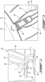
- each of the struts 26 has an airfoil body with a hollow core 32, the airfoil body having opposed pressure and suction sides 36, 38 extending chordwise from a leading edge 40 to a trailing edge 42 and spanwise from a radially inner end 44 to a radially outer end 46 ( Figs. 1 and 4 ).
- the hollow core 32 of the struts 26 may provide an internal passageway for service lines L and the like.
- the thermal differential growth between the struts 46 and the cases 22, 24 of the TEC may result in high stress concentration in the junction region J ( Fig. 2 ) of the leading edge 40 of the struts 26 and the inner case 24.
- the tensile stress in region J of the strut leading edge 40 can be reduced to an acceptable level by locally providing a leading edge stiffener 50 at the junction of the leading edge 40 with the inner case 24.
- the leading edge stiffener 50 is provided in the form of an internal core structure at the radially inner end 44 of the leading edge 40 of the struts 26.
- the internal core structure is configured to locally reinforce the struts 26 where high stress concentrations have been observed.
- the leading edge stiffener 50 is integrally cast with the associated strut 26 has an internal mass projecting into the hollow core 32 at the radially inner end 44 of the strut 26. Such an embedded cast structure allows to locally increasing the wall thickness of the leading edge 40 at the inner end 44 of the strut to reduce the stress concentration thereat.
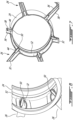
- the leading edge stiffener 50 projects radially inwardly beyond the airfoil body of the struts 26 to merge with a stiffener ring 52 projecting from a radially inner surface 53 of the inner case 24.
- the stiffener ring 52 extends along a full circumference of the inner case 24 and the leading stiffeners 50 radiate from different circumferential locations around the stiffener ring 52 into respective hollow cores 32 of the struts 26.
- the leading edge stiffeners 50 of the struts 26 around the inner case 24 are, thus, structurally interconnected via the stiffener ring 52. As best shown in Fig.
- the stiffener ring 52 is disposed to axially span the leading edge 40 of the airfoil body of the struts 26.
- the combination of the leading edge stiffeners 50 of the struts 26 with the stiffener ring 52 on the inner case 24 allows distributing the loads outside the struts 26, thereby relieving stress from the struts 26.
- the leading edge stiffeners 50 and the stiffener ring 52 can cooperate to remove tensile stress in the strut leading edge 40 when there is a high delta temperature between the struts 26 and cases 22, 24 of the TEC 15.
- the leading edge stiffeners 50 and the stiffener ring 52 eliminate the need for a heavy structural inner ring, thereby providing weight savings.
- the leading edge stiffener 50 has a radial height (D) which is greater than or equal to one-third of the radial height (A) of the annular exhaust gas path 20a.
- the stiffener ring 52 has a radial height (C) which is greater than or equal to two-thirds of its axial length (B).
- the leading edge stiffener 50 projects into the hollow core 32 by a distance (F) which is greater than or equal to the thickness (E) of the leading edge wall of the strut 26 at an intermediate location generally midway between the outer and inner cases 22, 24.
- leading edge stiffener 50 at least locally doubles the leading edge wall thickness of the airfoil body of the strut 26.
- the axial length (B) of the stiffener ring 52 is greater than or equal to half the leading edge stiffener height (D).
- the leading edge stiffener 50 has a width (W) in a circumferential direction.
- the width (W) generally corresponds to that of the leading edge 40. That is the leading edge stiffener 50 is comprised between the opposed sides 36, 38 of the airfoil body of the strut 26.
- leading edge stiffener 50 may have a generally rectangular face facing the interior of the hollow airfoil body of the strut. Also, as shown in Figs. 4 and 5 , the leading edge stiffener 50 may taper in a radially outward direction (that is in a direction away from the stiffener ring 52).
Landscapes
- Engineering & Computer Science (AREA)
- Mechanical Engineering (AREA)
- General Engineering & Computer Science (AREA)
- Turbine Rotor Nozzle Sealing (AREA)
Claims (11)
- Turbinenabgasgehäuse (15), umfassend:ein Außengehäuse (22);ein Innengehäuse (24), das eine radial äußere Fläche und eine radial innere Fläche (53) gegenüber der radial äußeren Fläche aufweist;einen ringförmigen Abgasweg (20a) zwischen dem Außengehäuse (22) und dem Innengehäuse (24), wobei die radial äußere Fläche des Innengehäuses (24) eine radial innere Begrenzung des ringförmigen Abgaswegs (20a) bildet; undeine Vielzahl von Streben (26), die sich über den ringförmigen Gasweg (20a) erstrecken und das Innengehäuse (24) strukturell mit dem Außengehäuse (22) verbinden, wobei mindestens eine der Vielzahl von Streben (26) einen Tragflächenprofilkörper mit einem hohlen Kern (32) aufweist, wobei der Tragflächenprofilkörper gegenüberliegende Seiten (36, 38) aufweist, die sich in Sehnenrichtung von einer Vorderkante (40) zu einer Hinterkante (42) und in Spannweitenrichtung von einem radial inneren Ende (44) zu einem radial äußeren Ende (46) erstrecken,dadurch gekennzeichnet, dass:
die mindestens eine der Vielzahl von Streben (26) eine Vorderkantenverstärkung (50) an ihrem radial inneren Ende (44) aufweist, wobei die Vorderkantenverstärkung (50) in den hohlen Kern (32) hineinragt und in einen Verstärkungsring (52) übergeht, der von der radial inneren Fläche (53) des Innengehäuses (24) hervorragt, wobei sich die Vorderkantenverstärkung (50) relativ zu der radial inneren Begrenzung des ringförmigen Abgaswegs (20a) radial nach außen erstreckt. - Turbinenabgasgehäuse (15) nach Anspruch 1, wobei der ringförmige Abgasweg (20a) eine radiale Höhe (A) zwischen dem Innengehäuse (24) und dem Außengehäuse (22) aufweist und die Vorderkantenverstärkung (50) eine radiale Höhe (D) aufweist, die größer oder gleich einem Drittel der radialen Höhe (A) des ringförmigen Abgaswegs (20a) ist.
- Turbinenabgasgehäuse (15) nach Anspruch 1 oder 2, wobei der Verstärkungsring eine axiale Länge (B) und eine radiale Höhe (C) aufweist, die größer oder gleich zwei Dritteln der axialen Länge (B) ist.
- Turbinenabgasgehäuse (15) nach einem der vorhergehenden Ansprüche, wobei die Vorderkantenverstärkung (50) eine Vorderkantenwandstärke (E) des Tragflächenprofilkörpers an dem inneren Ende (44) der mindestens einen der Vielzahl von Streben (26) mindestens lokal verdoppelt.
- Turbinenabgasgehäuse (15) nach einem der vorhergehenden Ansprüche, wobei die Vorderkantenverstärkung (50) eine Breite (W) in einer Umfangsrichtung aufweist und die Breite (W) einer Abmessung der Vorderkante (40) der mindestens einen der Vielzahl von Streben (26) in der Umfangsrichtung zwischen den gegenüberliegenden Seiten (36, 38) des Tragflächenprofilkörpers entspricht.
- Turbinenabgasgehäuse (15) nach einem der vorhergehenden Ansprüche, wobei die Vorderkantenverstärkung (50) einstückig mit der mindestens einen der Streben (26) als punktuelle Innenwandverstärkungsmasse an der Vorderkante (40) des inneren Endes (44) des Tragflächenprofilkörpers der mindestens einen der Vielzahl von Streben (26) gegossen ist.
- Turbinenabgasgehäuse (15) nach einem der vorhergehenden Ansprüche, wobei die Vorderkantenverstärkung (50) radial nach innen über den Tragflächenprofilkörper der mindestens einen der Vielzahl von Streben (26) hinausragt.
- Turbinenabgasgehäuse (15) nach einem der vorhergehenden Ansprüche, wobei sich der Verstärkungsring (52) in Umfangsrichtung entlang eines Vollkreises erstreckt, die Vielzahl von Streben (26) jeweils jeweilige Vorderkantenverstärkungen (50) aufweisen und die jeweiligen Vorderkantenverstärkungen (50) der Vielzahl von Streben (26) an in Umfangsrichtung beabstandeten Stellen um den Verstärkungsring (52) mit dem Verstärkungsring (52) verbunden sind.
- Turbinenabgasgehäuse (15) nach Anspruch 8, wobei der Verstärkungsring (52) die Vorderkanten (40) der Streben (26) axial überspannt.
- Turbinenabgasgehäuse (15) nach Anspruch 8 oder 9, wobei der Verstärkungsring (52) und die jeweiligen Vorderkantenverstärkungen (50) der Vielzahl von Streben (26) einstückig als einheitlicher Körper gegossen sind.
- Turbinenabgasgehäuse (15) nach einem der Ansprüche 8 bis 10, wobei eine oder die axiale Länge (B) des Verstärkungsrings (52) größer oder gleich der Hälfte der radialen Höhe (D) der Vorderkantenverstärkung (50) ist.
Applications Claiming Priority (1)
| Application Number | Priority Date | Filing Date | Title |
|---|---|---|---|
| US17/331,736 US11448097B1 (en) | 2021-05-27 | 2021-05-27 | Turbine exhaust strut internal core structure |
Publications (2)
| Publication Number | Publication Date |
|---|---|
| EP4095360A1 EP4095360A1 (de) | 2022-11-30 |
| EP4095360B1 true EP4095360B1 (de) | 2025-04-16 |
Family
ID=81850731
Family Applications (1)
| Application Number | Title | Priority Date | Filing Date |
|---|---|---|---|
| EP22175646.3A Active EP4095360B1 (de) | 2021-05-27 | 2022-05-26 | Verstärkungsstrebe eines turbinenaustrittsgehäuses |
Country Status (3)
| Country | Link |
|---|---|
| US (1) | US11448097B1 (de) |
| EP (1) | EP4095360B1 (de) |
| CA (1) | CA3160074A1 (de) |
Families Citing this family (4)
| Publication number | Priority date | Publication date | Assignee | Title |
|---|---|---|---|---|
| US11629615B2 (en) * | 2021-05-27 | 2023-04-18 | Pratt & Withney Canada Corp. | Strut reinforcing structure for a turbine exhaust case |
| US11898467B2 (en) | 2022-02-11 | 2024-02-13 | Pratt & Whitney Canada Corp. | Aircraft engine struts with stiffening protrusions |
| US12065950B1 (en) * | 2023-04-06 | 2024-08-20 | Pratt & Whitney Canada Corp. | Structural scroll case |
| US20260002452A1 (en) * | 2024-06-28 | 2026-01-01 | Pratt & Whitney Canada Corp. | Core gas path boundary structure for gas turbine engine |
Family Cites Families (10)
| Publication number | Priority date | Publication date | Assignee | Title |
|---|---|---|---|---|
| US5746574A (en) * | 1997-05-27 | 1998-05-05 | General Electric Company | Low profile fluid joint |
| FR2917458B1 (fr) | 2007-06-13 | 2009-09-25 | Snecma Sa | Moyeu de carter d'echappement comportant des nervures de repartition de contraintes |
| FR2997444B1 (fr) | 2012-10-31 | 2018-07-13 | Snecma | Moyeu de carter pour une turbomachine |
| WO2014105619A1 (en) * | 2012-12-29 | 2014-07-03 | United Technologies Corporation | Multi-function boss for a turbine exhaust case |
| EP2938844B1 (de) * | 2012-12-29 | 2017-02-08 | United Technologies Corporation | Auf einem hitzeschild basierende führungsrippen für ein turbinenabgasgehäuse |
| WO2014197037A2 (en) * | 2013-03-11 | 2014-12-11 | United Technologies Corporation | Bench aft sub-assembly for turbine exhaust case fairing |
| US10227895B2 (en) * | 2013-12-20 | 2019-03-12 | Pratt & Whitney Canada Corp. | Gas turbine case and reinforcement strut for same |
| JP6203090B2 (ja) * | 2014-03-14 | 2017-09-27 | 三菱日立パワーシステムズ株式会社 | 排気室入口側部材、排気室、ガスタービンおよび最終段タービン動翼取出方法 |
| US20160186614A1 (en) * | 2014-08-27 | 2016-06-30 | United Technologies Corporation | Turbine exhaust case assembly |
| GB2566751B (en) | 2017-09-26 | 2020-07-15 | Gkn Aerospace Sweden Ab | Divot for outer case shroud |
-
2021
- 2021-05-27 US US17/331,736 patent/US11448097B1/en active Active
-
2022
- 2022-05-12 CA CA3160074A patent/CA3160074A1/en active Pending
- 2022-05-26 EP EP22175646.3A patent/EP4095360B1/de active Active
Also Published As
| Publication number | Publication date |
|---|---|
| EP4095360A1 (de) | 2022-11-30 |
| CA3160074A1 (en) | 2022-11-27 |
| US11448097B1 (en) | 2022-09-20 |
Similar Documents
| Publication | Publication Date | Title |
|---|---|---|
| EP4095360B1 (de) | Verstärkungsstrebe eines turbinenaustrittsgehäuses | |
| US10697471B2 (en) | Gas turbine engine vanes | |
| EP3369891B1 (de) | Gasturbinenleitschaufeln | |
| US10370986B2 (en) | Nozzle and nozzle assembly for gas turbine engine | |
| US9879542B2 (en) | Platform with curved edges adjacent suction side of airfoil | |
| US9784133B2 (en) | Turbine frame and airfoil for turbine frame | |
| US20150176494A1 (en) | Supporting structure for a gas turbine engine | |
| JP5124276B2 (ja) | ガスタービン中間構造および該中間構造を含むガスタービンエンジン | |
| EP4095359B1 (de) | Strebenverstärkung für ein turbinenaustrittsgehäuse | |
| EP2870364B1 (de) | Stützstruktur für einen gasturbinenmotor | |
| EP2917510A1 (de) | Überleitkanal zur verwendung in einem gasturbinenmotor und montageverfahren | |
| US20180179901A1 (en) | Turbine blade with contoured tip shroud | |
| WO2010002294A1 (en) | A vane for a gas turbine component, a gas turbine component and a gas turbine engine | |
| EP3730738B1 (de) | Turbinenanordnung für ein gasturbinentriebwerk mit verbundstoffleitschaufel mit keramischer matrix | |
| US20180087391A1 (en) | Casing with suction arm for axial turbine engine | |
| EP2795071B1 (de) | Gasturbinenmotorkomponente | |
| US20240117744A1 (en) | Aerofoil for a gas turbine engine | |
| US11415012B1 (en) | Tandem stator with depressions in gaspath wall | |
| US11585277B2 (en) | Stiffened rotor shaft for a gas turbine engine | |
| US12352175B2 (en) | Annulus filler for a gas turbine engine | |
| US20250283414A1 (en) | Turbine engine with a blade assembly having a set of cooling conduits | |
| US20230073422A1 (en) | Stator with depressions in gaspath wall adjacent trailing edges | |
| US20230072853A1 (en) | Stator with depressions in gaspath wall adjacent leading edges |
Legal Events
| Date | Code | Title | Description |
|---|---|---|---|
| PUAI | Public reference made under article 153(3) epc to a published international application that has entered the european phase |
Free format text: ORIGINAL CODE: 0009012 |
|
| STAA | Information on the status of an ep patent application or granted ep patent |
Free format text: STATUS: THE APPLICATION HAS BEEN PUBLISHED |
|
| AK | Designated contracting states |
Kind code of ref document: A1 Designated state(s): AL AT BE BG CH CY CZ DE DK EE ES FI FR GB GR HR HU IE IS IT LI LT LU LV MC MK MT NL NO PL PT RO RS SE SI SK SM TR |
|
| STAA | Information on the status of an ep patent application or granted ep patent |
Free format text: STATUS: REQUEST FOR EXAMINATION WAS MADE |
|
| 17P | Request for examination filed |
Effective date: 20230530 |
|
| RBV | Designated contracting states (corrected) |
Designated state(s): AL AT BE BG CH CY CZ DE DK EE ES FI FR GB GR HR HU IE IS IT LI LT LU LV MC MK MT NL NO PL PT RO RS SE SI SK SM TR |
|
| GRAP | Despatch of communication of intention to grant a patent |
Free format text: ORIGINAL CODE: EPIDOSNIGR1 |
|
| STAA | Information on the status of an ep patent application or granted ep patent |
Free format text: STATUS: GRANT OF PATENT IS INTENDED |
|
| INTG | Intention to grant announced |
Effective date: 20241118 |
|
| GRAS | Grant fee paid |
Free format text: ORIGINAL CODE: EPIDOSNIGR3 |
|
| GRAA | (expected) grant |
Free format text: ORIGINAL CODE: 0009210 |
|
| STAA | Information on the status of an ep patent application or granted ep patent |
Free format text: STATUS: THE PATENT HAS BEEN GRANTED |
|
| AK | Designated contracting states |
Kind code of ref document: B1 Designated state(s): AL AT BE BG CH CY CZ DE DK EE ES FI FR GB GR HR HU IE IS IT LI LT LU LV MC MK MT NL NO PL PT RO RS SE SI SK SM TR |
|
| REG | Reference to a national code |
Ref country code: GB Ref legal event code: FG4D |
|
| REG | Reference to a national code |
Ref country code: CH Ref legal event code: EP Ref country code: DE Ref legal event code: R096 Ref document number: 602022013118 Country of ref document: DE |
|
| REG | Reference to a national code |
Ref country code: IE Ref legal event code: FG4D |
|
| PGFP | Annual fee paid to national office [announced via postgrant information from national office to epo] |
Ref country code: DE Payment date: 20250423 Year of fee payment: 4 |
|
| PGFP | Annual fee paid to national office [announced via postgrant information from national office to epo] |
Ref country code: FR Payment date: 20250520 Year of fee payment: 4 |
|
| PGFP | Annual fee paid to national office [announced via postgrant information from national office to epo] |
Ref country code: AT Payment date: 20250721 Year of fee payment: 4 |
|
| REG | Reference to a national code |
Ref country code: NL Ref legal event code: MP Effective date: 20250416 |
|
| PG25 | Lapsed in a contracting state [announced via postgrant information from national office to epo] |
Ref country code: NL Free format text: LAPSE BECAUSE OF FAILURE TO SUBMIT A TRANSLATION OF THE DESCRIPTION OR TO PAY THE FEE WITHIN THE PRESCRIBED TIME-LIMIT Effective date: 20250416 |
|
| REG | Reference to a national code |
Ref country code: AT Ref legal event code: MK05 Ref document number: 1785828 Country of ref document: AT Kind code of ref document: T Effective date: 20250416 |
|
| PG25 | Lapsed in a contracting state [announced via postgrant information from national office to epo] |
Ref country code: FI Free format text: LAPSE BECAUSE OF FAILURE TO SUBMIT A TRANSLATION OF THE DESCRIPTION OR TO PAY THE FEE WITHIN THE PRESCRIBED TIME-LIMIT Effective date: 20250416 Ref country code: PT Free format text: LAPSE BECAUSE OF FAILURE TO SUBMIT A TRANSLATION OF THE DESCRIPTION OR TO PAY THE FEE WITHIN THE PRESCRIBED TIME-LIMIT Effective date: 20250818 Ref country code: ES Free format text: LAPSE BECAUSE OF FAILURE TO SUBMIT A TRANSLATION OF THE DESCRIPTION OR TO PAY THE FEE WITHIN THE PRESCRIBED TIME-LIMIT Effective date: 20250416 |
|
| REG | Reference to a national code |
Ref country code: LT Ref legal event code: MG9D |
|
| PG25 | Lapsed in a contracting state [announced via postgrant information from national office to epo] |
Ref country code: NO Free format text: LAPSE BECAUSE OF FAILURE TO SUBMIT A TRANSLATION OF THE DESCRIPTION OR TO PAY THE FEE WITHIN THE PRESCRIBED TIME-LIMIT Effective date: 20250716 Ref country code: GR Free format text: LAPSE BECAUSE OF FAILURE TO SUBMIT A TRANSLATION OF THE DESCRIPTION OR TO PAY THE FEE WITHIN THE PRESCRIBED TIME-LIMIT Effective date: 20250717 |
|
| PG25 | Lapsed in a contracting state [announced via postgrant information from national office to epo] |
Ref country code: PL Free format text: LAPSE BECAUSE OF FAILURE TO SUBMIT A TRANSLATION OF THE DESCRIPTION OR TO PAY THE FEE WITHIN THE PRESCRIBED TIME-LIMIT Effective date: 20250416 |
|
| PG25 | Lapsed in a contracting state [announced via postgrant information from national office to epo] |
Ref country code: BG Free format text: LAPSE BECAUSE OF FAILURE TO SUBMIT A TRANSLATION OF THE DESCRIPTION OR TO PAY THE FEE WITHIN THE PRESCRIBED TIME-LIMIT Effective date: 20250416 |
|
| PG25 | Lapsed in a contracting state [announced via postgrant information from national office to epo] |
Ref country code: HR Free format text: LAPSE BECAUSE OF FAILURE TO SUBMIT A TRANSLATION OF THE DESCRIPTION OR TO PAY THE FEE WITHIN THE PRESCRIBED TIME-LIMIT Effective date: 20250416 Ref country code: AT Free format text: LAPSE BECAUSE OF FAILURE TO SUBMIT A TRANSLATION OF THE DESCRIPTION OR TO PAY THE FEE WITHIN THE PRESCRIBED TIME-LIMIT Effective date: 20250416 |
|
| PG25 | Lapsed in a contracting state [announced via postgrant information from national office to epo] |
Ref country code: RS Free format text: LAPSE BECAUSE OF FAILURE TO SUBMIT A TRANSLATION OF THE DESCRIPTION OR TO PAY THE FEE WITHIN THE PRESCRIBED TIME-LIMIT Effective date: 20250716 |
|
| PG25 | Lapsed in a contracting state [announced via postgrant information from national office to epo] |
Ref country code: IS Free format text: LAPSE BECAUSE OF FAILURE TO SUBMIT A TRANSLATION OF THE DESCRIPTION OR TO PAY THE FEE WITHIN THE PRESCRIBED TIME-LIMIT Effective date: 20250816 |
|
| PG25 | Lapsed in a contracting state [announced via postgrant information from national office to epo] |
Ref country code: LV Free format text: LAPSE BECAUSE OF FAILURE TO SUBMIT A TRANSLATION OF THE DESCRIPTION OR TO PAY THE FEE WITHIN THE PRESCRIBED TIME-LIMIT Effective date: 20250416 |
|
| REG | Reference to a national code |
Ref country code: CH Ref legal event code: H13 Free format text: ST27 STATUS EVENT CODE: U-0-0-H10-H13 (AS PROVIDED BY THE NATIONAL OFFICE) Effective date: 20251223 |
|
| PG25 | Lapsed in a contracting state [announced via postgrant information from national office to epo] |
Ref country code: DK Free format text: LAPSE BECAUSE OF FAILURE TO SUBMIT A TRANSLATION OF THE DESCRIPTION OR TO PAY THE FEE WITHIN THE PRESCRIBED TIME-LIMIT Effective date: 20250416 Ref country code: SM Free format text: LAPSE BECAUSE OF FAILURE TO SUBMIT A TRANSLATION OF THE DESCRIPTION OR TO PAY THE FEE WITHIN THE PRESCRIBED TIME-LIMIT Effective date: 20250416 |
|
| PG25 | Lapsed in a contracting state [announced via postgrant information from national office to epo] |
Ref country code: LU Free format text: LAPSE BECAUSE OF NON-PAYMENT OF DUE FEES Effective date: 20250526 |
|
| PG25 | Lapsed in a contracting state [announced via postgrant information from national office to epo] |
Ref country code: CH Free format text: LAPSE BECAUSE OF NON-PAYMENT OF DUE FEES Effective date: 20250531 |
|
| PG25 | Lapsed in a contracting state [announced via postgrant information from national office to epo] |
Ref country code: CZ Free format text: LAPSE BECAUSE OF FAILURE TO SUBMIT A TRANSLATION OF THE DESCRIPTION OR TO PAY THE FEE WITHIN THE PRESCRIBED TIME-LIMIT Effective date: 20250416 |
|
| PG25 | Lapsed in a contracting state [announced via postgrant information from national office to epo] |
Ref country code: EE Free format text: LAPSE BECAUSE OF FAILURE TO SUBMIT A TRANSLATION OF THE DESCRIPTION OR TO PAY THE FEE WITHIN THE PRESCRIBED TIME-LIMIT Effective date: 20250416 |
|
| PG25 | Lapsed in a contracting state [announced via postgrant information from national office to epo] |
Ref country code: SK Free format text: LAPSE BECAUSE OF FAILURE TO SUBMIT A TRANSLATION OF THE DESCRIPTION OR TO PAY THE FEE WITHIN THE PRESCRIBED TIME-LIMIT Effective date: 20250416 |
|
| PG25 | Lapsed in a contracting state [announced via postgrant information from national office to epo] |
Ref country code: IT Free format text: LAPSE BECAUSE OF FAILURE TO SUBMIT A TRANSLATION OF THE DESCRIPTION OR TO PAY THE FEE WITHIN THE PRESCRIBED TIME-LIMIT Effective date: 20250416 |
|
| PG25 | Lapsed in a contracting state [announced via postgrant information from national office to epo] |
Ref country code: MC Free format text: LAPSE BECAUSE OF FAILURE TO SUBMIT A TRANSLATION OF THE DESCRIPTION OR TO PAY THE FEE WITHIN THE PRESCRIBED TIME-LIMIT Effective date: 20250416 |