EP4095353B1 - Verdichterabschnitt mit statorschaufelanordnung mit trennlinie - Google Patents
Verdichterabschnitt mit statorschaufelanordnung mit trennlinie Download PDFInfo
- Publication number
- EP4095353B1 EP4095353B1 EP22173727.3A EP22173727A EP4095353B1 EP 4095353 B1 EP4095353 B1 EP 4095353B1 EP 22173727 A EP22173727 A EP 22173727A EP 4095353 B1 EP4095353 B1 EP 4095353B1
- Authority
- EP
- European Patent Office
- Prior art keywords
- split
- line
- compressor
- stator vane
- section
- Prior art date
- Legal status (The legal status is an assumption and is not a legal conclusion. Google has not performed a legal analysis and makes no representation as to the accuracy of the status listed.)
- Active
Links
Images


Classifications
-
- F—MECHANICAL ENGINEERING; LIGHTING; HEATING; WEAPONS; BLASTING
- F01—MACHINES OR ENGINES IN GENERAL; ENGINE PLANTS IN GENERAL; STEAM ENGINES
- F01D—NON-POSITIVE DISPLACEMENT MACHINES OR ENGINES, e.g. STEAM TURBINES
- F01D9/00—Stators
- F01D9/02—Nozzles; Nozzle boxes; Stator blades; Guide conduits, e.g. individual nozzles
- F01D9/04—Nozzles; Nozzle boxes; Stator blades; Guide conduits, e.g. individual nozzles forming ring or sector
- F01D9/041—Nozzles; Nozzle boxes; Stator blades; Guide conduits, e.g. individual nozzles forming ring or sector using blades
-
- F—MECHANICAL ENGINEERING; LIGHTING; HEATING; WEAPONS; BLASTING
- F01—MACHINES OR ENGINES IN GENERAL; ENGINE PLANTS IN GENERAL; STEAM ENGINES
- F01D—NON-POSITIVE DISPLACEMENT MACHINES OR ENGINES, e.g. STEAM TURBINES
- F01D25/00—Component parts, details, or accessories, not provided for in, or of interest apart from, other groups
- F01D25/24—Casings; Casing parts, e.g. diaphragms, casing fastenings
- F01D25/26—Double casings; Measures against temperature strain in casings
- F01D25/265—Vertically split casings; Clamping arrangements therefor
-
- F—MECHANICAL ENGINEERING; LIGHTING; HEATING; WEAPONS; BLASTING
- F01—MACHINES OR ENGINES IN GENERAL; ENGINE PLANTS IN GENERAL; STEAM ENGINES
- F01D—NON-POSITIVE DISPLACEMENT MACHINES OR ENGINES, e.g. STEAM TURBINES
- F01D9/00—Stators
- F01D9/02—Nozzles; Nozzle boxes; Stator blades; Guide conduits, e.g. individual nozzles
- F01D9/04—Nozzles; Nozzle boxes; Stator blades; Guide conduits, e.g. individual nozzles forming ring or sector
- F01D9/042—Nozzles; Nozzle boxes; Stator blades; Guide conduits, e.g. individual nozzles forming ring or sector fixing blades to stators
-
- F—MECHANICAL ENGINEERING; LIGHTING; HEATING; WEAPONS; BLASTING
- F04—POSITIVE - DISPLACEMENT MACHINES FOR LIQUIDS; PUMPS FOR LIQUIDS OR ELASTIC FLUIDS
- F04D—NON-POSITIVE-DISPLACEMENT PUMPS
- F04D19/00—Axial-flow pumps
- F04D19/02—Multi-stage pumps
-
- F—MECHANICAL ENGINEERING; LIGHTING; HEATING; WEAPONS; BLASTING
- F04—POSITIVE - DISPLACEMENT MACHINES FOR LIQUIDS; PUMPS FOR LIQUIDS OR ELASTIC FLUIDS
- F04D—NON-POSITIVE-DISPLACEMENT PUMPS
- F04D29/00—Details, component parts, or accessories
- F04D29/40—Casings; Connections of working fluid
- F04D29/52—Casings; Connections of working fluid for axial pumps
- F04D29/54—Fluid-guiding means, e.g. diffusers
- F04D29/541—Specially adapted for elastic fluid pumps
- F04D29/542—Bladed diffusers
- F04D29/544—Blade shapes
Definitions
- the present disclosure relates generally to an improved split-line stator vane assembly.
- the present disclosure relates to a compressor section of a turbomachine having an improved split-line stator vane assembly.
- Turbomachines such as a land-based power generating gas turbine
- a gas turbine engine generally includes a compressor section, a combustion section, a turbine section, and an exhaust section.
- the compressor section progressively increases the pressure of a working fluid entering the gas turbine engine and supplies this compressed working fluid to the combustion section.
- the compressed working fluid and a fuel e.g., natural gas
- the combustion gases flow from the combustion section into the turbine section where they expand to produce work.
- expansion of the combustion gases in the turbine section may rotate a rotor shaft connected, e.g., to a generator to produce electricity.
- the combustion gases then exit the gas turbine via the exhaust section.
- the compressor section includes a compressor casing, a plurality of stator vanes mounted to the compressor casing, and a plurality of rotor blades mounted to a rotor of the turbomachine.
- the compressor casing is a stationary component that includes an upper portion and a lower portion, which are connected to one another to surround the plurality of rotor blades. Where the upper portion and the lower portion of the compressor casing meet and are joined is typically referred to as a split-line of the compressor section.
- stator vanes mounted to the compressor casing near the split-line experience higher stresses and are more difficult to assemble and disassemble.
- an improved compressor section having a split-line stator vane assembly is desired in the art.
- an improved split-line stator vane assembly that reduces operational stresses, increases hardware life, and simplifies installation, is desired.
- EP 3 339 608 B1 discloses a gas turbine engine including a combustor section, a turbine section, and a compressor section, the compressor section supporting a stator assembly comprising a plurality of stator vanes.
- the plurality of stator vanes comprises a split-line stator vane assembly including a first split-line stator vane that has a first shank with a first platform portion and a first mounting portion that extends radially outward of the first platform portion and that is mounted to one of the upper casing portion or the lower casing portion of the compressor casing.
- a first airfoil extends radially inward of the platform portion.
- the first shank includes a protrusion that extends circumferentially beyond the split-line.
- a second split-line stator vane includes a second shank with a second platform portion and a second mounting portion that extends radially outward of the second platform portion and that is mounted to the other of the upper casing portion or the lower casing portion of the compressor casing.
- a second airfoil extends radially inward of the second platform portion.
- the second shank includes a recess that extends circumferentially away from the split-line.
- US 2009/185899 A1 discloses an array of stator vane segments for a compressor or turbine section of a gas turbine engine, each stator vane segment being separated by an axially extending joint from an adjacent stator vane segment and being releasably mounted to an outer engine casing.
- Each stator vane segment has: a number of vane airfoils spanning radially between an inner platform and an outer platform, and the outer platform includes a casing mounting fastener on an outer surface and mating lateral joint edges extending between forward and aft edges.
- the mating lateral joint edges have mating tongues and recesses that define an overlapping joint having a radial thickness equal to the radial thickness of the outer platform.
- US5788456A relates to a prior art turbine split casing.
- a compressor section of a turbomachine includes a compressor casing that has an upper casing portion coupled to a lower casing portion such that a split-line is defined between the upper casing portion and the lower casing portion.
- a plurality of stator vanes is circumferentially arranged in a stage of the compressor casing.
- the plurality of stator vanes comprises a split-line stator vane assembly mounted in the compressor casing at the split-line.
- the split-line stator vane assembly includes a first split-line stator vane that has a first shank with a first platform portion and a first mounting portion that extends radially outward of the first platform portion and that is mounted to one of the upper casing portion or the lower casing portion of the compressor casing.
- a first airfoil extends radially inward of the platform portion.
- the first shank includes a protrusion that extends circumferentially beyond the split-line.
- a second split-line stator vane includes a second shank with a second platform portion and a second mounting portion that extends radially outward of the second platform portion and that is mounted to the other of the upper casing portion or the lower casing portion of the compressor casing.
- a second airfoil extends radially inward of the second platform portion.
- the second shank includes a recess that extends circumferentially away from the split-line.
- a turbomachine in accordance with another embodiment, includes a combustor section, a turbine section downstream of the combustor section, and a compressor section upstream of the combustor section, the compressor section configured as described above.
- fluid may be a gas or a liquid.
- fluid communication means that a fluid is capable of making the connection between the areas specified.
- upstream refers to the relative direction with respect to fluid flow in a fluid pathway.
- upstream refers to the direction from which the fluid flows
- downstream refers to the direction to which the fluid flows.
- upstream and downstream as used herein may also refer to a flow of electricity.
- radially refers to the relative direction that is substantially perpendicular to an axial centerline of a particular component
- axially refers to the relative direction that is substantially parallel and/or coaxially aligned to an axial centerline of a particular component
- circumferentially refers to the relative direction that extends around the axial centerline of a particular component.
- the approximating language may correspond to the precision of an instrument for measuring the value, or the precision of the methods or machines for constructing or manufacturing the components and/or systems. In at least some instances, the approximating language may correspond to the precision of an instrument for measuring the value, or the precision of the methods or machines for constructing or manufacturing the components and/or systems. For example, the approximating language may refer to being within a 1, 2, 4, 5, 10, 15, or 20 percent margin in either individual values, range(s) of values and/or endpoints defining range(s) of values. When used in the context of an angle or direction, such terms include within ten degrees greater or less than the stated angle or direction. For example, "generally vertical” includes directions within ten degrees of vertical in any direction, e.g., clockwise or counter-clockwise.
- Coupled refers to both direct coupling, fixing, or attaching, as well as indirect coupling, fixing, or attaching through one or more intermediate components or features, unless otherwise specified herein.
- the terms “comprises,” “comprising,” “includes,” “including,” “has,” “having” or any other variation thereof, are intended to cover a non-exclusive inclusion.
- a process, method, article, or apparatus that comprises a list of features is not necessarily limited only to those features but may include other features not expressly listed or inherent to such process, method, article, or apparatus.
- “or” refers to an inclusive- or and not to an exclusive- or. For example, a condition A or B is satisfied by any one of the following: A is true (or present) and B is false (or not present), A is false (or not present) and B is true (or present), and both A and B are true (or present).
- FIG. 1 illustrates a schematic diagram of one embodiment of a turbomachine, which in the illustrated embodiment is a gas turbine 10.
- a gas turbine 10 an industrial or land-based gas turbine is shown and described herein, the present disclosure is not limited to a land-based and/or industrial gas turbine unless otherwise specified in the claims.
- the invention as described herein may be used in any type of turbomachine including but not limited to a steam turbine, an aircraft gas turbine, or a marine gas turbine.
- gas turbine 10 generally includes an inlet section 12, a compressor section 14 disposed downstream of the inlet section 12, a plurality of combustors (not shown) within a combustor section 16 disposed downstream of the compressor section 14, a turbine section 18 disposed downstream of the combustor section 16, and an exhaust section 20 disposed downstream of the turbine section 18. Additionally, the gas turbine 10 may include one or more shafts 22 coupled between the compressor section 14 and the turbine section 18.
- the compressor section 14 may generally include a plurality of rotor disks 24 (one of which is shown) and a plurality of rotor blades 26 extending radially outwardly from and connected to each rotor disk 24. Each rotor disk 24 in turn may be coupled to or form a portion of the shaft 22 that extends through the compressor section 14.
- the turbine section 18 may generally include a plurality of rotor disks 28 (one of which is shown) and a plurality of rotor blades 30 extending radially outwardly from and being interconnected to each rotor disk 28. Each rotor disk 28 in turn may be coupled to or form a portion of the shaft 22 that extends through the turbine section 18.
- the turbine section 18 further includes an outer casing 31 that circumferentially surrounds the portion of the shaft 22 and the rotor blades 30, thereby at least partially defining a hot gas path 32 through the turbine section 18.
- a working fluid such as air flows through the inlet section 12 and into the compressor section 14 where the air is progressively compressed, thus providing pressurized air to the combustors of the combustor section 16.
- the pressurized air is mixed with fuel and burned within each combustor to produce combustion gases 34.
- the combustion gases 34 flow through the hot gas path 32 from the combustor section 16 into the turbine section 18, wherein energy (kinetic and/or thermal) is transferred from the combustion gases 34 to the rotor blades 30, causing the shaft 22 to rotate.
- the mechanical rotational energy may then be used to power the compressor section 14 and/or to generate electricity.
- the combustion gases 34 exiting the turbine section 18 may then be exhausted from the gas turbine 10 via the exhaust section 20.
- FIG. 2 illustrates a cross-sectional side view of an embodiment of the compressor section 14 of the gas turbine 10 of FIG. 1 , which is shown as a multi-stage axial compressor section 14, in accordance with embodiments of the present disclosure.
- the gas turbine 10 may define a cylindrical coordinate system.
- the cylindrical coordinate system may define an axial direction A (e.g., downstream direction) substantially parallel to and/or along an axial centerline 23 of the gas turbine 10, a radial direction R perpendicular to the axial centerline or rotary axis 23, and a circumferential direction C extending around the axial centerline 23.
- air 15 may enter the compressor section 14 in the axial direction A through the inlet section 12 and may be pressurized in the multi-stage axial compressor section 14.
- the compressed air may then be mixed with fuel for combustion within the combustor section 16 to drive the turbine section 18, which rotates the shaft 22 in the circumferential direction C and, thus, the multi-stage axial compressor section 14.
- the rotation of the shaft 22 also causes one or more rotor blades 44 (e.g., compressor rotor blades) within the multi-stage axial compressor section 14 to draw in and pressurize the air received by the inlet section 12.
- the multi-stage axial compressor section 14 may include a rotor assembly 46 having a plurality of rotor disks 24. Rotor blades 44 may extend radially outward from the rotor disks 24. The entire rotor assembly 46 (e.g., rotor disks 24 and rotor blades 44) may rotate in the circumferential direction C during operation of the gas turbine 10.
- the rotor assembly 46 may be surrounded by a compressor casing 48.
- the compressor casing may be static or stationary, such that the rotor assembly 46 rotates relative to the compressor casing 48.
- Stator vanes 50 e.g., variable stator vanes and/or fixed stator vanes
- one or more stages of the stator vanes 50 may be variable stator vanes, such that an angle of the stator vane 50 may be selectively actuated (e.g., by a controller 200).
- first two stages of the compressor section 14 may include variable stator vanes.
- the rotor blades 44 and stator vanes 50 may be arranged in an alternating fashion, such that most of the rotor blades 44 are disposed between two stator vanes 50 in the axial direction A.
- the compressor casing 48 of the compressor section 14 or the inlet section 12 may have one or more sets of inlet guide vanes 52 (IGVs) (e.g., variable IGV stator vanes).
- IGVs inlet guide vanes 52
- the inlet guide vanes 52 may be mounted to the compressor casing 48, spaced apart from one another in the circumferential direction C, and may be operable to control the amount of air 15 that enters the compressor section 14.
- an outlet 56 of the compressor section 14 may have a set of outlet guide vanes 58 (OGVs).
- the OGVs 58 may be mounted to the compressor casing 48, spaced apart from one another in the circumferential direction C, and may be operable to control the amount of air 15 that exits the compressor section 14.
- variable stator vane, the IGVs 52, and the OGVs may each be configured to vary its vane angle relative to the gas flow (e.g., air flow) by rotating the vane, 52, 58 about an axis of rotation (e.g., radially oriented vane shaft).
- each variable stator vane (including the IGVs 52 and the OGVs 58) may be otherwise stationary relative to the rotor blades 44.
- the variable stator vanes, the IGVs 52, and the OGVs 58 may be coupled to an actuator 19 (e.g., electric drive, pneumatic drive, or hydraulic drive).
- the actuators 19 may be in operable communication (e.g., electrical communication) with a controller 200.
- the controller may be operable to selectively vary the vane angle.
- all of the stator vanes 50 may be fixed, such that the stator vanes 50 are configured to remain in a fixed angular position (e.g., the vane angle does not vary).
- the compressor section 14 may include a plurality of rows or stages arranged in a serial flow order, such as between 2 to 30, 2 to 25, 2 to 20, 2 to 14, or 2 to 10 rows or stages, or any specific number or range therebetween.
- Each stage may include a plurality of rotor blades 44 circumferentially spaced about the axial centerline 23 and a plurality of stator vanes 50 circumferentially spaced about the axial centerline 23.
- the multi-stage axial compressor section 14 may include 2 to 1000, 5 to 500, or 10 to 100 of circumferentially arranged rotor blades 44, and 2 to 1000, 5 to 500, or 10 to 100 of circumferentially arranged stator vanes 50.
- the illustrated embodiment of the multi-stage axial compressor section 14 includes 22 stages (e.g., S1-S22).
- each stage has a set of rotor blades 44 disposed at a first axial position and a set of stator vanes 50 disposed at a second axial position along the length of the compressor section 14.
- each stage has the rotor blades 44 and stator vanes 50 axially offset from one another, such that the compressor section 14 has an alternating arrangement of rotor blades 44 and stator vanes 50 one set after another along the length of the compressor section 14.
- Each set of rotor blades 44 extends (e.g., in a spaced arrangement) in the circumferential direction C about the shaft 22, and each set of stator vanes 50 extends (e.g., in a spaced arrangement) in the circumferential direction C within the compressor casing 48.
- FIG. 2 illustrates an embodiment of the compressor section 14 having twenty two stages arranged in a serial flow order and identified as follows: first stage S1, second stage S2, third stage S3, fourth stage S4, fifth stage S5, sixth stage S6, seventh stage S7, eighth stage S8, ninth stage S9, tenth stage S10, eleventh stage S11, twelfth stage S12, thirteenth stage S13, and fourteenth stage S14, fifteenth stage S15, sixteenth stage S16, seventeenth stage S17, eighteenth stage S18, nineteenth stage S19, twentieth stage S20, twenty-first stage S21, and twenty-second stage S22.
- each stage may include rotor blades 44 and stator vanes 50 (e.g., fixed stator vanes 50 and/or variable stator vanes).
- stator vanes 50 e.g., fixed stator vanes 50 and/or variable stator vanes.
- a rotor blade 44 disposed within one of the sections S1-S22 of the compressor section 14 may be referred to by whichever stage it is disposed within, e.g., "a first stage compressor rotor blade,” "a second stage compressor rotor blade,” “a third stage compressor rotor blade,” etc.
- the rotor blades 44 may rotate circumferentially about the compressor casing 48 and the stator vanes 50. Rotation of the rotor blades 44 may result in air entering the inlet section 12. The air is then subsequently compressed as it traverses the various stages (e.g., first stage S1 to twenty-second stage S22) of the compressor section 14 and moves in the axial direction 38 downstream of the multi-stage axial compressor section 14. The compressed air may then exit through the outlet 56 of the multi-stage axial compressor section 14. As discussed above, the outlet 56 may have a set of outlet guide vanes 58 (OGVs). The compressed air that exits the compressor section 14 may be mixed with fuel, directed to the combustor section 16, directed to the turbine section 18, or elsewhere in the gas turbine 10.
- OGVs outlet guide vanes 58
- FIGS. 3 and 4 each illustrate a schematic cross-sectional view of a compressor section 14, in accordance with embodiments of the present disclosure.
- FIGS. 3 and 4 each illustrate a single stage (such as any one of S1-S22 of the compressor section 14) of stator vanes 50 circumferentially arranged in, and mounted in, a compressor casing 48 of the compressor section 14.
- the compressor casing 48 includes an upper casing portion 60 and a lower casing portion 62, such that a first half (e.g., about 50%) of the stator vanes 50 are mounted in the upper casing portion 60 and a second half (e.g., about 50%) of the stator vanes 50 are mounted in the lower casing portion 62.
- the first half of the stator vanes 50 may be installed in the upper casing portion 60, and the second half of the stator vanes 50 may be installed in the lower casing portion 62. Subsequently, the upper casing portion 60 may be coupled to the lower casing portion 62.
- the upper casing portion 60 and the lower casing portion 62 couple to one another such that a split-line 64 is defined between the upper casing portion 60 and the lower casing portion 62.
- the split-line 64 may be a horizontal line defined at the junction (e.g., the contact point or plane) of the upper casing portion 60 and the lower casing portion 62.
- the split-line 64 may extend along the radial direction R through a center point of the compressor section 14.
- the stator vane assembly 70 includes a first split-line stator vane 76 mounted in one of the upper casing portion 60 or the lower casing portion 62. Additionally, the stator vane assembly 70 further includes a second split-line stator vane 78 mounted in the other of the upper casing portion 60 or the lower casing portion 62, such that the first split-line stator vane 76 and the second split-line stator vane 78 are disposed adjacent to one another and at least partially contact the split-line 64 of the compressor section 14.
- the first split-line stator vane 76 includes a protrusion 80 that intersects (and extends across) the split-line 64 of the compressor section 14, and the second split-line stator vane 78 defines a recess 82 that that is complementary to the protrusion (such that the recess 82 receives the protrusion 80).
- the recess 82 may correspond in shape and size to the protrusion 80, such that they may flushly contact one another when assembled ( FIG. 4 ).
- the first split-line stator vane 76 is mounted in one of the upper casing portion 60 or the lower casing portion 62, and the protrusion 80 extends across the split-line 64 into the recess 82 disposed in the second split-line stator vane 78 mounted in the other of the upper casing portion 60 or the lower casing portion 62.
- the plurality of stator vanes 50 may further include a plurality of main-body stator vanes 72 and a plurality of spacers 74 mounted in the compressor casing 48.
- the main-body stator vanes 72 and the spacers 74 may be mounted in an alternating arrangement in both the upper casing portion 60 and the lower casing portion 62 between the split-line stator vane assemblies 70.
- all of the main-body stator vanes 72 and spacers 74 in the upper casing portion 60 may be disposed circumferentially between a first split-line stator vane assembly 70 and a second split-line stator vane assembly 70, such that none of the main-body stator vanes 72 or spacers 74 in the upper casing portion 60 contact or intersect with the split-line 64 of the compressor section 14.
- all of the main-body stator vanes 72 and spacers 74 in the lower casing portion 62 may be disposed circumferentially between a first split-line stator vane assembly 70 and a second split-line stator vane assembly 70, such that none of the main-body stator vanes 72 or spacers 74 in the lower casing portion 62 contact or intersect with the split-line 64 of the compressor section 14.
- the main-body stator vane 72 may include a platform portion and a mounting body.
- the platform portion of the main-body stator vane 72 may define a main circumferential width (e.g., measured between the pressure-side slash face and the suction-side slash face).
- the first platform portion 84 of the first split-line stator vane 76 may define a first circumferential width
- the second platform portion 94 of the second split-line stator vane 78 may define a second circumferential width.
- the main circumferential width of the main-body stator vane 72 may be smaller than both the first circumferential width of the first split-line stator vane 76 and the second circumferential width of the second split-line stator vane 78.
- FIG. 5 illustrates a perspective view of a single stage of stator vanes 50 isolated from the compressor casing 48.
- the split-line stator vane assemblies 70 are circled with a dashed line.
- the split-line stator vane assemblies 70 may include a first split-line stator vane assembly 102 at a first end (e.g., a first end of the compressor casing 48 at the split-line 64), and a second split-line stator vane assembly 104 at a second end (e.g., a second end of the compressor casing 48 at the split-line 64).
- the first split-line stator vane assembly 102 may be diametrically opposed to the second split-line stator vane assembly 104.
- each of the main-body stator vanes 72 may circumferentially neighbor one of two spacers 74 of the plurality of spacers 74 or one spacer 74 of the plurality of spacers 74 and the split-line stator vane assembly 70.
- each main-body stator vane 72 may be positioned between two spacers 74.
- one or more main-body stator vanes 72 may be disposed between one spacer 74 and a split-line stator vane (such as the first split-line stator vane 76 or the second split-line stator vane 78).
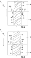
- FIG. 6 illustrates an enlarged plan view of the first split-line assembly 102
- FIG. 7 illustrates an enlarged plan view of the second split-line assembly 104, in accordance with embodiments of the present disclosure.
- the first split-line stator vane 76 and the second split-line stator vane 78 may directly neighbor one another when arranged in the compressor casing 48, such that the first split-line stator vane 76 and the second split-line stator vane 78 are in direct contact with one another (e.g., no spacers or intermediate components positioned between the split-line stator vanes 76 and 78).
- first split-line stator vane 76 and the second split-line stator vane 78 may each at least partially contact (and/or extend across) the split-line 64.
- the protrusion 80 extends circumferentially beyond the split-line 64 (e.g., beyond the split-line 64 and into the recess 82 which is correspondingly shaped).
- the recess 82 extends circumferentially away from the split-line 64, in order to define a space for the protrusion 80 to extend.
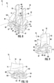
- FIG. 8 illustrates a perspective view of a split-line stator vane assembly 70
- FIGS. 9 and 10 each illustrate different perspective views of a first split-line stator vane 76 of the split-line stator vane assembly 70, in accordance with embodiments of the present disclosure.
- the first split-line stator vane 76 includes a first shank 75 having a first platform portion 84 and a first mounting portion 86.
- the protrusion 80 is defined by the shank 75 (i.e., collectively defined by the first platform portion 84 and the first mounting portion 86). Additionally, the first mounting portion 86 extends radially outward of the first platform portion 84.
- the first mounting portion 86 is mounted to one of the upper casing portion 60 or the lower casing portion 62 of the compressor casing 48.
- the first mounting portion 86 may include a protrusion 87 that is slidably received by a corresponding recess defined in the compressor casing 48.
- the first mounting portion 86 may be a dovetail or other suitable mounting construction that is slidably received by a correspondingly shaped slot defined in the compressor casing 48.
- the second split-line stator vane 78 includes a second shank 79 having a second platform portion 94 and a second mounting portion 96.
- the recess 82 is defined by the second shank 79 (i.e., collectively defined by the second platform portion 94 and the second mounting portion 96).
- the second mounting portion 96 extends radially outward of the second platform portion 94.
- the second mounting portion 96 is mounted to one of the upper casing portion 60 or the lower casing portion 62 of the compressor casing 48. Particularly, the second mounting portion 96 is mounted to the other of the upper casing portion 60 or the lower casing portion 62 that the first mounting portion 86 is mounted on.
- the second mounting portion 96 may include a protrusion 97 that may be slidably received by a corresponding recess defined in the compressor casing 48.
- the second mounting portion 96 may be a dovetail or other suitable mounting construction that is slidably received by a correspondingly shaped slot defined in the compressor casing 48.
- Each airfoil 88 may include a pressure-side surface 90 and an opposing suction-side surface 92.
- the pressure-side surface 90 and the suction-side surface 92 meet or intersect at a leading edge 91 and a trailing edge 93 of the airfoil 88.
- the leading edge 91 and the trailing edge 93 may be spaced apart from one another and define the terminal ends of the airfoil 88.
- the pressure-side surface 90 generally defines an aerodynamic, concave external surface of the airfoil 88.
- the suction-side surface 92 may generally define an aerodynamic, convex external surface of the airfoil 88.
- the leading edge 91 of airfoil 88 may be the first portion of the airfoil 88 to engage, i.e., be exposed to, the compressed air within the compressor section 14. Compressed air may be guided along the aerodynamic contour of airfoil 88 from the leading edge 91 to the trailing edge 93.
- each airfoil 88 may include a root or first end 98, which intersects with and extends radially outwardly from the respective platform portion of the stator vane. Each airfoil 88 terminates radially at a second end or tip 99 of the airfoil 88.
- the root 98 of the airfoil 88 may be defined at an intersection between the airfoil 88 and the platform portion of the stator vane.
- the first shank 75 may define a first pressure-side slash face 100 and a first suction-side slash face 102.
- the first pressure-side slash face 100 and the first suction-side slash face 102 may be circumferentially spaced apart from one another and disposed on opposite sides of the airfoil 88.
- the second shank 79 may define a second pressure-side slash face 104 and a second suction-side slash face 106.
- the second pressure-side slash face 104 and the second suction-side slash face 106 may be circumferentially spaced apart from one another and disposed on opposite sides of the airfoil 88.
- the first pressure-side slash face 100 contacts the second suction-side slash face 106.
- the first pressure-side slash face 100 of the first split-line stator vane 76 and the second suction-side slash face 106 of the second split-line stator vane 78 may be entirely in contact with one another (e.g., both faces 100 and 106 may be contoured to correspond with one another such that they are in flush contact).
- the protrusion 80 may be defined on the first pressure-side slash face 100, and the recess 82 may be defined on the second suction-side slash face 106. In this way, the protrusion 80 of the first split-line stator vane 76 may be entirely in contact with the recess 82 of the second split-line stator vane 78.
- the first suction-side slash face 102 and the second pressure-side slash face 104 are planar surfaces (e.g., entirely planar surfaces).
- the first suction-side slash face 102 and the second pressure-side slash face 104 may be substantially flat surfaces (e.g., not including any curvatures, protrusions, or recesses). This allows the first suction-side slash face 102 and the second pressure-side slash face 104 to be in flush contact with one of a spacer 74 or a main-body stator vane 72 when installed in the casing 48 of the compressor section 14.
- the first pressure-side slash face 100 includes a first planar portion 101
- the second suction-side slash face 106 includes a second planar portion 107.
- the first planar portion 101 and the second planar portion 107 may be generally parallel to one another and generally parallel to the first suction-side slash face 102 and the second pressure-side slash face 104.
- the first planar portion 101 and the second planar portion 107 may be aligned with the split-line 64.
- a portion 89 of the airfoil 88 belonging to the first split-line stator vane 76 is coupled to the protrusion 80 of the first split-line stator vane 76 such that the portion 89 of the first airfoil extends circumferentially beyond the split-line 64.
- the portion 89 may include the leading edge 91 of the airfoil 88.
Landscapes
- Engineering & Computer Science (AREA)
- Mechanical Engineering (AREA)
- General Engineering & Computer Science (AREA)
- Physics & Mathematics (AREA)
- Geometry (AREA)
- Structures Of Non-Positive Displacement Pumps (AREA)
Claims (9)
- Verdichterabschnitt (14) einer Turbomaschine (10), umfassend:ein Verdichtergehäuse (48) mit einem oberen Gehäuseabschnitt (60), der mit einem unteren Gehäuseabschnitt (62) verbunden ist, so dass zwischen dem oberen Gehäuseabschnitt (60) und dem unteren Gehäuseabschnitt (62) eine Trennlinie (64) definiert ist; undeine Vielzahl von Statorschaufeln (50), die in einer Stufe des Verdichtergehäuses (48) umfangsmäßig angeordnet sind, wobei die Vielzahl von Statorschaufeln (50) eine Trennlinien-Statorschaufelanordnung (70) umfasst, die an der Trennlinie (64) im Verdichtergehäuse (48) montiert ist, wobei die Trennlinien-Statorschaufelanordnung (70) dadurch gekennzeichnet ist, dass sie ferner umfasst:eine erste Trennlinien-Statorschaufel (76) mit einem ersten Schaft (75) mit einem ersten Plattformabschnitt (84) und einem ersten Montageabschnitt (86), der sich radial nach außen vom ersten Plattformabschnitt (84) erstreckt und an einem oberen Gehäuseabschnitt (60) oder einem unteren Gehäuseabschnitt (62) des Verdichtergehäuses (48) montiert ist, und einem ersten Schaufelblatt (88), das radial nach innen vom ersten Plattformabschnitt (84) verläuft, wobei der erste Schaft (75) einen Vorsprung (80) einschließt, der sich in Umfangsrichtung über die Trennlinie (64) hinaus erstreckt; undeine zweite Trennlinien-Statorschaufel (78) mit einem zweiten Schaft (79) mit einem zweiten Plattformabschnitt (94) und einem zweiten Montageabschnitt (96), der sich radial nach außen vom zweiten Plattformabschnitt (94) erstreckt und an dem anderen der oberen Gehäuseabschnitte (60) oder unteren Gehäuseabschnitte (62) des Verdichtergehäuses (48) montiert ist, und ein zweites Schaufelblatt (88), das sich radial nach innen vom zweiten Plattformabschnitt (94) erstreckt, wobei der zweite Schaft (79) eine Aussparung (82) aufweist, die komplementär zum Vorsprung (80) ist, der sich in Umfangsrichtung von der Trennlinie (64) weg erstreckt.
- Verdichterabschnitt (14) nach Anspruch 1, wobei der erste Schaft (75) eine erste druckseitige Schrägfläche (100) und eine erste saugseitige Schrägfläche (102) definiert, wobei der zweite Schaft (79) eine zweite druckseitige Schrägfläche (104) und eine zweite saugseitige Schrägfläche (106) definiert, und wobei die erste druckseitige Schrägfläche (100) des ersten Schafts (75) die zweite saugseitige Schrägfläche (106) des zweiten Schafts (79) berührt.
- Verdichterabschnitt (14) nach Anspruch 2, wobei der Vorsprung (80) auf der ersten druckseitigen Schrägfläche (100) definiert ist, und wobei die Vertiefung (82) auf der zweiten saugseitigen Schrägfläche (106) definiert ist.
- Verdichterabschnitt (14) nach Anspruch 3, wobei die erste saugseitige Schrägfläche (102) und die zweite druckseitige Schrägfläche (104) ebene Flächen sind.
- Verdichterabschnitt (14) nach Anspruch 3, wobei die erste druckseitige Schrägfläche (100) einen ersten ebenen Abschnitt (101) einschließt; wobei die zweite saugseitige Schrägfläche (106) einen zweiten ebenen Abschnitt (107) einschließt; und wobei der erste planare Abschnitt (101) und der zweite planare Abschnitt (107) an der Trennlinie (64) ausgerichtet sind.
- Verdichterabschnitt (14) nach Anspruch 1, wobei ein Abschnitt des ersten Schaufelblatts (88) mit dem Vorsprung (80) des ersten Plattformabschnitts (84) der ersten Trennlinien-Statorschaufel (76) verbunden ist, so dass der Abschnitt des ersten Schaufelblatts (88) sich in Umfangsrichtung über die Trennlinie (64) hinaus erstreckt.
- Verdichterabschnitt (14) nach Anspruch 1, wobei die Vielzahl von Statorschaufeln eine Vielzahl von Hauptkörper-Statorschaufeln (72) und eine Vielzahl von Abstandshaltern (74) umfasst, die im Verdichtergehäuse montiert sind.
- Verdichterabschnitt (14) nach Anspruch 7, wobei jede Hauptkörper-Statorschaufel der Vielzahl von Hauptkörper-Statorschaufeln (72) umfangsmäßig zwischen zwei Abstandshaltern der Vielzahl von Abstandshaltern (74) oder zwischen einem Abstandshalter der Vielzahl von Abstandshaltern (74) und der Trennlinien-Statorschaufelanordnung (70) angeordnet ist.
- Turbomaschine (10), umfassend:einen Brennkammerabschnitt (16);einen Turbinenabschnitt (18) stromabwärts des Brennkammerabschnitts (16); undeinen Verdichterabschnitt (14) nach einem der vorstehenden Ansprüche, wobei der Verdichterabschnitt (14) stromaufwärts des Brennkammerabschnitts (16) angeordnet ist.
Applications Claiming Priority (2)
| Application Number | Priority Date | Filing Date | Title |
|---|---|---|---|
| IN202111023487 | 2021-05-26 | ||
| US17/389,562 US11629606B2 (en) | 2021-05-26 | 2021-07-30 | Split-line stator vane assembly |
Publications (2)
| Publication Number | Publication Date |
|---|---|
| EP4095353A1 EP4095353A1 (de) | 2022-11-30 |
| EP4095353B1 true EP4095353B1 (de) | 2025-01-29 |
Family
ID=81748577
Family Applications (1)
| Application Number | Title | Priority Date | Filing Date |
|---|---|---|---|
| EP22173727.3A Active EP4095353B1 (de) | 2021-05-26 | 2022-05-17 | Verdichterabschnitt mit statorschaufelanordnung mit trennlinie |
Country Status (2)
| Country | Link |
|---|---|
| EP (1) | EP4095353B1 (de) |
| CN (1) | CN115405568A (de) |
Family Cites Families (4)
| Publication number | Priority date | Publication date | Assignee | Title |
|---|---|---|---|---|
| US5788456A (en) * | 1997-02-21 | 1998-08-04 | Dresser-Rand Company | Turbine diaphragm assembly and method thereof |
| US8128354B2 (en) * | 2007-01-17 | 2012-03-06 | Siemens Energy, Inc. | Gas turbine engine |
| US8092165B2 (en) * | 2008-01-21 | 2012-01-10 | Pratt & Whitney Canada Corp. | HP segment vanes |
| US10309235B2 (en) * | 2012-08-27 | 2019-06-04 | United Technologies Corporation | Shiplap cantilevered stator |
-
2022
- 2022-05-05 CN CN202210491968.3A patent/CN115405568A/zh active Pending
- 2022-05-17 EP EP22173727.3A patent/EP4095353B1/de active Active
Also Published As
| Publication number | Publication date |
|---|---|
| CN115405568A (zh) | 2022-11-29 |
| EP4095353A1 (de) | 2022-11-30 |
Similar Documents
| Publication | Publication Date | Title |
|---|---|---|
| EP2659112B1 (de) | Gasturbinenmotor und schaufelsystem mit veränderbarer wölbung | |
| EP2204534B1 (de) | Synchronisierung von Gasturbinenschaufeln | |
| US11767768B2 (en) | Unison member for variable guide vane | |
| EP3835550B1 (de) | Laufschaufel für eine strömungsmaschine und strömungsmaschine | |
| EP2938829A1 (de) | Plattform mit gekrümmten konturen neben der saugseite einer schaufel | |
| EP3839218B1 (de) | Verbesserte rotorschaufeldichtungsstrukturen | |
| EP3347571A1 (de) | Anordnung für eine gasturbine | |
| US12281591B2 (en) | T-fairing installation tooling assembly | |
| EP3885532B1 (de) | Turbinenlaufschaufel mit kühlkreislauf | |
| EP4095353B1 (de) | Verdichterabschnitt mit statorschaufelanordnung mit trennlinie | |
| US11629606B2 (en) | Split-line stator vane assembly | |
| EP3412869B1 (de) | Turbomaschinenrotorschaufel | |
| EP3828386B1 (de) | Turbomaschinenrotorschaufel mit variabler elliptischer hinterkante | |
| EP3889392B1 (de) | Turbomaschinenlaufschaufel mit einem kühlkreislauf mit versetzter rippe | |
| EP3828390B1 (de) | Turbomaschinenleitschaufel mit einem profil mit einer gekrümmten hinterkante | |
| EP3882436B1 (de) | Laufschaufel für eine strömungsmaschine und zugehörige strömungsmaschine | |
| EP4043698A1 (de) | Verstellbare leitschaufelanordnung für ein gasturbinentriebwerk und gasturbinentriebwerk | |
| US12460557B1 (en) | Variable pitch airfoil assembly for a gas turbine engine | |
| US11674400B2 (en) | Gas turbine engine nozzles | |
| US20250179922A1 (en) | Turbine engine with a nozzle having cooling features | |
| US12571318B1 (en) | Airfoil having flex elements with multi-dimensional curvature | |
| US12286899B2 (en) | Trailing edge cooling circuit | |
| EP4509699A1 (de) | Hinterkantenkühlkreislauf für turbomaschinenschaufel |
Legal Events
| Date | Code | Title | Description |
|---|---|---|---|
| PUAI | Public reference made under article 153(3) epc to a published international application that has entered the european phase |
Free format text: ORIGINAL CODE: 0009012 |
|
| STAA | Information on the status of an ep patent application or granted ep patent |
Free format text: STATUS: THE APPLICATION HAS BEEN PUBLISHED |
|
| AK | Designated contracting states |
Kind code of ref document: A1 Designated state(s): AL AT BE BG CH CY CZ DE DK EE ES FI FR GB GR HR HU IE IS IT LI LT LU LV MC MK MT NL NO PL PT RO RS SE SI SK SM TR |
|
| STAA | Information on the status of an ep patent application or granted ep patent |
Free format text: STATUS: REQUEST FOR EXAMINATION WAS MADE |
|
| 17P | Request for examination filed |
Effective date: 20221207 |
|
| RBV | Designated contracting states (corrected) |
Designated state(s): AL AT BE BG CH CY CZ DE DK EE ES FI FR GB GR HR HU IE IS IT LI LT LU LV MC MK MT NL NO PL PT RO RS SE SI SK SM TR |
|
| RAP1 | Party data changed (applicant data changed or rights of an application transferred) |
Owner name: GENERAL ELECTRIC TECHNOLOGY GMBH |
|
| REG | Reference to a national code |
Ref country code: DE Ref legal event code: R079 Free format text: PREVIOUS MAIN CLASS: F01D0009040000 Ipc: F01D0009020000 Ref country code: DE Ref legal event code: R079 Ref document number: 602022009962 Country of ref document: DE Free format text: PREVIOUS MAIN CLASS: F01D0009040000 Ipc: F01D0009020000 |
|
| GRAP | Despatch of communication of intention to grant a patent |
Free format text: ORIGINAL CODE: EPIDOSNIGR1 |
|
| STAA | Information on the status of an ep patent application or granted ep patent |
Free format text: STATUS: GRANT OF PATENT IS INTENDED |
|
| RIC1 | Information provided on ipc code assigned before grant |
Ipc: F04D 19/02 20060101ALI20241016BHEP Ipc: F04D 29/54 20060101ALI20241016BHEP Ipc: F01D 25/26 20060101ALI20241016BHEP Ipc: F01D 25/24 20060101ALI20241016BHEP Ipc: F01D 9/04 20060101ALI20241016BHEP Ipc: F01D 9/02 20060101AFI20241016BHEP |
|
| GRAS | Grant fee paid |
Free format text: ORIGINAL CODE: EPIDOSNIGR3 |
|
| INTG | Intention to grant announced |
Effective date: 20241115 |
|
| GRAA | (expected) grant |
Free format text: ORIGINAL CODE: 0009210 |
|
| STAA | Information on the status of an ep patent application or granted ep patent |
Free format text: STATUS: THE PATENT HAS BEEN GRANTED |
|
| AK | Designated contracting states |
Kind code of ref document: B1 Designated state(s): AL AT BE BG CH CY CZ DE DK EE ES FI FR GB GR HR HU IE IS IT LI LT LU LV MC MK MT NL NO PL PT RO RS SE SI SK SM TR |
|
| REG | Reference to a national code |
Ref country code: GB Ref legal event code: FG4D |
|
| REG | Reference to a national code |
Ref country code: CH Ref legal event code: EP |
|
| REG | Reference to a national code |
Ref country code: DE Ref legal event code: R096 Ref document number: 602022009962 Country of ref document: DE |
|
| REG | Reference to a national code |
Ref country code: IE Ref legal event code: FG4D Ref country code: NL Ref legal event code: FP |
|
| PGFP | Annual fee paid to national office [announced via postgrant information from national office to epo] |
Ref country code: NL Payment date: 20250423 Year of fee payment: 4 |
|
| PG25 | Lapsed in a contracting state [announced via postgrant information from national office to epo] |
Ref country code: RS Free format text: LAPSE BECAUSE OF FAILURE TO SUBMIT A TRANSLATION OF THE DESCRIPTION OR TO PAY THE FEE WITHIN THE PRESCRIBED TIME-LIMIT Effective date: 20250429 |
|
| PG25 | Lapsed in a contracting state [announced via postgrant information from national office to epo] |
Ref country code: FI Free format text: LAPSE BECAUSE OF FAILURE TO SUBMIT A TRANSLATION OF THE DESCRIPTION OR TO PAY THE FEE WITHIN THE PRESCRIBED TIME-LIMIT Effective date: 20250129 |
|
| PG25 | Lapsed in a contracting state [announced via postgrant information from national office to epo] |
Ref country code: PL Free format text: LAPSE BECAUSE OF FAILURE TO SUBMIT A TRANSLATION OF THE DESCRIPTION OR TO PAY THE FEE WITHIN THE PRESCRIBED TIME-LIMIT Effective date: 20250129 |
|
| PGFP | Annual fee paid to national office [announced via postgrant information from national office to epo] |
Ref country code: DE Payment date: 20250423 Year of fee payment: 4 |
|
| PG25 | Lapsed in a contracting state [announced via postgrant information from national office to epo] |
Ref country code: ES Free format text: LAPSE BECAUSE OF FAILURE TO SUBMIT A TRANSLATION OF THE DESCRIPTION OR TO PAY THE FEE WITHIN THE PRESCRIBED TIME-LIMIT Effective date: 20250129 |
|
| REG | Reference to a national code |
Ref country code: LT Ref legal event code: MG9D |
|
| PG25 | Lapsed in a contracting state [announced via postgrant information from national office to epo] |
Ref country code: NO Free format text: LAPSE BECAUSE OF FAILURE TO SUBMIT A TRANSLATION OF THE DESCRIPTION OR TO PAY THE FEE WITHIN THE PRESCRIBED TIME-LIMIT Effective date: 20250429 Ref country code: IS Free format text: LAPSE BECAUSE OF FAILURE TO SUBMIT A TRANSLATION OF THE DESCRIPTION OR TO PAY THE FEE WITHIN THE PRESCRIBED TIME-LIMIT Effective date: 20250529 |
|
| REG | Reference to a national code |
Ref country code: AT Ref legal event code: MK05 Ref document number: 1763612 Country of ref document: AT Kind code of ref document: T Effective date: 20250129 |
|
| PG25 | Lapsed in a contracting state [announced via postgrant information from national office to epo] |
Ref country code: HR Free format text: LAPSE BECAUSE OF FAILURE TO SUBMIT A TRANSLATION OF THE DESCRIPTION OR TO PAY THE FEE WITHIN THE PRESCRIBED TIME-LIMIT Effective date: 20250129 |
|
| PG25 | Lapsed in a contracting state [announced via postgrant information from national office to epo] |
Ref country code: PT Free format text: LAPSE BECAUSE OF FAILURE TO SUBMIT A TRANSLATION OF THE DESCRIPTION OR TO PAY THE FEE WITHIN THE PRESCRIBED TIME-LIMIT Effective date: 20250529 Ref country code: LV Free format text: LAPSE BECAUSE OF FAILURE TO SUBMIT A TRANSLATION OF THE DESCRIPTION OR TO PAY THE FEE WITHIN THE PRESCRIBED TIME-LIMIT Effective date: 20250129 |
|
| PG25 | Lapsed in a contracting state [announced via postgrant information from national office to epo] |
Ref country code: GR Free format text: LAPSE BECAUSE OF FAILURE TO SUBMIT A TRANSLATION OF THE DESCRIPTION OR TO PAY THE FEE WITHIN THE PRESCRIBED TIME-LIMIT Effective date: 20250430 Ref country code: BG Free format text: LAPSE BECAUSE OF FAILURE TO SUBMIT A TRANSLATION OF THE DESCRIPTION OR TO PAY THE FEE WITHIN THE PRESCRIBED TIME-LIMIT Effective date: 20250129 |
|
| PG25 | Lapsed in a contracting state [announced via postgrant information from national office to epo] |
Ref country code: AT Free format text: LAPSE BECAUSE OF FAILURE TO SUBMIT A TRANSLATION OF THE DESCRIPTION OR TO PAY THE FEE WITHIN THE PRESCRIBED TIME-LIMIT Effective date: 20250129 |
|
| PG25 | Lapsed in a contracting state [announced via postgrant information from national office to epo] |
Ref country code: SE Free format text: LAPSE BECAUSE OF FAILURE TO SUBMIT A TRANSLATION OF THE DESCRIPTION OR TO PAY THE FEE WITHIN THE PRESCRIBED TIME-LIMIT Effective date: 20250129 |
|
| RAP4 | Party data changed (patent owner data changed or rights of a patent transferred) |
Owner name: GE VERNOVA TECHNOLOGY GMBH |
|
| PG25 | Lapsed in a contracting state [announced via postgrant information from national office to epo] |
Ref country code: SM Free format text: LAPSE BECAUSE OF FAILURE TO SUBMIT A TRANSLATION OF THE DESCRIPTION OR TO PAY THE FEE WITHIN THE PRESCRIBED TIME-LIMIT Effective date: 20250129 |
|
| PG25 | Lapsed in a contracting state [announced via postgrant information from national office to epo] |
Ref country code: DK Free format text: LAPSE BECAUSE OF FAILURE TO SUBMIT A TRANSLATION OF THE DESCRIPTION OR TO PAY THE FEE WITHIN THE PRESCRIBED TIME-LIMIT Effective date: 20250129 |
|
| PG25 | Lapsed in a contracting state [announced via postgrant information from national office to epo] |
Ref country code: IT Free format text: LAPSE BECAUSE OF FAILURE TO SUBMIT A TRANSLATION OF THE DESCRIPTION OR TO PAY THE FEE WITHIN THE PRESCRIBED TIME-LIMIT Effective date: 20250129 |
|
| PG25 | Lapsed in a contracting state [announced via postgrant information from national office to epo] |
Ref country code: EE Free format text: LAPSE BECAUSE OF FAILURE TO SUBMIT A TRANSLATION OF THE DESCRIPTION OR TO PAY THE FEE WITHIN THE PRESCRIBED TIME-LIMIT Effective date: 20250129 Ref country code: CZ Free format text: LAPSE BECAUSE OF FAILURE TO SUBMIT A TRANSLATION OF THE DESCRIPTION OR TO PAY THE FEE WITHIN THE PRESCRIBED TIME-LIMIT Effective date: 20250129 |
|
| PG25 | Lapsed in a contracting state [announced via postgrant information from national office to epo] |
Ref country code: RO Free format text: LAPSE BECAUSE OF FAILURE TO SUBMIT A TRANSLATION OF THE DESCRIPTION OR TO PAY THE FEE WITHIN THE PRESCRIBED TIME-LIMIT Effective date: 20250129 |
|
| PG25 | Lapsed in a contracting state [announced via postgrant information from national office to epo] |
Ref country code: SK Free format text: LAPSE BECAUSE OF FAILURE TO SUBMIT A TRANSLATION OF THE DESCRIPTION OR TO PAY THE FEE WITHIN THE PRESCRIBED TIME-LIMIT Effective date: 20250129 |
|
| REG | Reference to a national code |
Ref country code: DE Ref legal event code: R097 Ref document number: 602022009962 Country of ref document: DE |
|
| PLBE | No opposition filed within time limit |
Free format text: ORIGINAL CODE: 0009261 |
|
| STAA | Information on the status of an ep patent application or granted ep patent |
Free format text: STATUS: NO OPPOSITION FILED WITHIN TIME LIMIT |
|
| REG | Reference to a national code |
Ref country code: CH Ref legal event code: L10 Free format text: ST27 STATUS EVENT CODE: U-0-0-L10-L00 (AS PROVIDED BY THE NATIONAL OFFICE) Effective date: 20251210 |
|
| REG | Reference to a national code |
Ref country code: CH Ref legal event code: H13 Free format text: ST27 STATUS EVENT CODE: U-0-0-H10-H13 (AS PROVIDED BY THE NATIONAL OFFICE) Effective date: 20251223 |
|
| 26N | No opposition filed |
Effective date: 20251030 |
|
| PG25 | Lapsed in a contracting state [announced via postgrant information from national office to epo] |
Ref country code: LU Free format text: LAPSE BECAUSE OF NON-PAYMENT OF DUE FEES Effective date: 20250517 |
|
| PG25 | Lapsed in a contracting state [announced via postgrant information from national office to epo] |
Ref country code: CH Free format text: LAPSE BECAUSE OF NON-PAYMENT OF DUE FEES Effective date: 20250531 |
|
| REG | Reference to a national code |
Ref country code: BE Ref legal event code: MM Effective date: 20250531 |
|
| PG25 | Lapsed in a contracting state [announced via postgrant information from national office to epo] |
Ref country code: MC Free format text: LAPSE BECAUSE OF FAILURE TO SUBMIT A TRANSLATION OF THE DESCRIPTION OR TO PAY THE FEE WITHIN THE PRESCRIBED TIME-LIMIT Effective date: 20250129 |
|
| PG25 | Lapsed in a contracting state [announced via postgrant information from national office to epo] |
Ref country code: IE Free format text: LAPSE BECAUSE OF NON-PAYMENT OF DUE FEES Effective date: 20250517 |
|
| PG25 | Lapsed in a contracting state [announced via postgrant information from national office to epo] |
Ref country code: BE Free format text: LAPSE BECAUSE OF NON-PAYMENT OF DUE FEES Effective date: 20250531 |
|
| PG25 | Lapsed in a contracting state [announced via postgrant information from national office to epo] |
Ref country code: FR Free format text: LAPSE BECAUSE OF NON-PAYMENT OF DUE FEES Effective date: 20250531 |