EP4095075A1 - Post-processing apparatus and image forming system incorporating the post-processing apparatus - Google Patents
Post-processing apparatus and image forming system incorporating the post-processing apparatus Download PDFInfo
- Publication number
- EP4095075A1 EP4095075A1 EP22169692.5A EP22169692A EP4095075A1 EP 4095075 A1 EP4095075 A1 EP 4095075A1 EP 22169692 A EP22169692 A EP 22169692A EP 4095075 A1 EP4095075 A1 EP 4095075A1
- Authority
- EP
- European Patent Office
- Prior art keywords
- tray
- ejection
- post
- sheet
- processing apparatus
- Prior art date
- Legal status (The legal status is an assumption and is not a legal conclusion. Google has not performed a legal analysis and makes no representation as to the accuracy of the status listed.)
- Granted
Links
Images




Classifications
-
- B—PERFORMING OPERATIONS; TRANSPORTING
- B65—CONVEYING; PACKING; STORING; HANDLING THIN OR FILAMENTARY MATERIAL
- B65H—HANDLING THIN OR FILAMENTARY MATERIAL, e.g. SHEETS, WEBS, CABLES
- B65H31/00—Pile receivers
- B65H31/26—Auxiliary devices for retaining articles in the pile
-
- B—PERFORMING OPERATIONS; TRANSPORTING
- B65—CONVEYING; PACKING; STORING; HANDLING THIN OR FILAMENTARY MATERIAL
- B65H—HANDLING THIN OR FILAMENTARY MATERIAL, e.g. SHEETS, WEBS, CABLES
- B65H31/00—Pile receivers
- B65H31/02—Pile receivers with stationary end support against which pile accumulates
-
- B—PERFORMING OPERATIONS; TRANSPORTING
- B65—CONVEYING; PACKING; STORING; HANDLING THIN OR FILAMENTARY MATERIAL
- B65H—HANDLING THIN OR FILAMENTARY MATERIAL, e.g. SHEETS, WEBS, CABLES
- B65H33/00—Forming counted batches in delivery pile or stream of articles
- B65H33/14—Forming counted batches in delivery pile or stream of articles by diverting batches to separate receivers
-
- B—PERFORMING OPERATIONS; TRANSPORTING
- B65—CONVEYING; PACKING; STORING; HANDLING THIN OR FILAMENTARY MATERIAL
- B65H—HANDLING THIN OR FILAMENTARY MATERIAL, e.g. SHEETS, WEBS, CABLES
- B65H31/00—Pile receivers
- B65H31/30—Arrangements for removing completed piles
-
- B—PERFORMING OPERATIONS; TRANSPORTING
- B65—CONVEYING; PACKING; STORING; HANDLING THIN OR FILAMENTARY MATERIAL
- B65H—HANDLING THIN OR FILAMENTARY MATERIAL, e.g. SHEETS, WEBS, CABLES
- B65H31/00—Pile receivers
- B65H31/30—Arrangements for removing completed piles
- B65H31/3009—Arrangements for removing completed piles by dropping, e.g. removing the pile support from under the pile
-
- B—PERFORMING OPERATIONS; TRANSPORTING
- B65—CONVEYING; PACKING; STORING; HANDLING THIN OR FILAMENTARY MATERIAL
- B65H—HANDLING THIN OR FILAMENTARY MATERIAL, e.g. SHEETS, WEBS, CABLES
- B65H37/00—Article or web delivery apparatus incorporating devices for performing specified auxiliary operations
- B65H37/04—Article or web delivery apparatus incorporating devices for performing specified auxiliary operations for securing together articles or webs, e.g. by adhesive, stitching or stapling
-
- B—PERFORMING OPERATIONS; TRANSPORTING
- B65—CONVEYING; PACKING; STORING; HANDLING THIN OR FILAMENTARY MATERIAL
- B65H—HANDLING THIN OR FILAMENTARY MATERIAL, e.g. SHEETS, WEBS, CABLES
- B65H43/00—Use of control, checking, or safety devices, e.g. automatic devices comprising an element for sensing a variable
- B65H43/06—Use of control, checking, or safety devices, e.g. automatic devices comprising an element for sensing a variable detecting, or responding to, completion of pile
-
- B—PERFORMING OPERATIONS; TRANSPORTING
- B65—CONVEYING; PACKING; STORING; HANDLING THIN OR FILAMENTARY MATERIAL
- B65H—HANDLING THIN OR FILAMENTARY MATERIAL, e.g. SHEETS, WEBS, CABLES
- B65H45/00—Folding thin material
- B65H45/12—Folding articles or webs with application of pressure to define or form crease lines
- B65H45/18—Oscillating or reciprocating blade folders
-
- B—PERFORMING OPERATIONS; TRANSPORTING
- B65—CONVEYING; PACKING; STORING; HANDLING THIN OR FILAMENTARY MATERIAL
- B65H—HANDLING THIN OR FILAMENTARY MATERIAL, e.g. SHEETS, WEBS, CABLES
- B65H2404/00—Parts for transporting or guiding the handled material
- B65H2404/60—Other elements in face contact with handled material
- B65H2404/69—Other means designated for special purpose
- B65H2404/692—Chute, e.g. inclined surface on which material slides by gravity
-
- B—PERFORMING OPERATIONS; TRANSPORTING
- B65—CONVEYING; PACKING; STORING; HANDLING THIN OR FILAMENTARY MATERIAL
- B65H—HANDLING THIN OR FILAMENTARY MATERIAL, e.g. SHEETS, WEBS, CABLES
- B65H2405/00—Parts for holding the handled material
- B65H2405/10—Cassettes, holders, bins, decks, trays, supports or magazines for sheets stacked substantially horizontally
- B65H2405/11—Parts and details thereof
- B65H2405/111—Bottom
- B65H2405/1115—Bottom with surface inclined, e.g. in width-wise direction
- B65H2405/11152—Bottom with surface inclined, e.g. in width-wise direction with surface inclined downwardly in transport direction
-
- B—PERFORMING OPERATIONS; TRANSPORTING
- B65—CONVEYING; PACKING; STORING; HANDLING THIN OR FILAMENTARY MATERIAL
- B65H—HANDLING THIN OR FILAMENTARY MATERIAL, e.g. SHEETS, WEBS, CABLES
- B65H2405/00—Parts for holding the handled material
- B65H2405/10—Cassettes, holders, bins, decks, trays, supports or magazines for sheets stacked substantially horizontally
- B65H2405/11—Parts and details thereof
- B65H2405/111—Bottom
- B65H2405/1116—Bottom with means for changing geometry
- B65H2405/11162—Front portion pivotable around an axis perpendicular to transport direction
-
- B—PERFORMING OPERATIONS; TRANSPORTING
- B65—CONVEYING; PACKING; STORING; HANDLING THIN OR FILAMENTARY MATERIAL
- B65H—HANDLING THIN OR FILAMENTARY MATERIAL, e.g. SHEETS, WEBS, CABLES
- B65H2405/00—Parts for holding the handled material
- B65H2405/10—Cassettes, holders, bins, decks, trays, supports or magazines for sheets stacked substantially horizontally
- B65H2405/11—Parts and details thereof
- B65H2405/111—Bottom
- B65H2405/1117—Bottom pivotable, e.g. around an axis perpendicular to transport direction, e.g. arranged at rear side of sheet support
-
- B—PERFORMING OPERATIONS; TRANSPORTING
- B65—CONVEYING; PACKING; STORING; HANDLING THIN OR FILAMENTARY MATERIAL
- B65H—HANDLING THIN OR FILAMENTARY MATERIAL, e.g. SHEETS, WEBS, CABLES
- B65H2405/00—Parts for holding the handled material
- B65H2405/10—Cassettes, holders, bins, decks, trays, supports or magazines for sheets stacked substantially horizontally
- B65H2405/11—Parts and details thereof
- B65H2405/112—Rear, i.e. portion opposite to the feeding / delivering side
- B65H2405/1124—Rear, i.e. portion opposite to the feeding / delivering side pivotable, details therefor
-
- B—PERFORMING OPERATIONS; TRANSPORTING
- B65—CONVEYING; PACKING; STORING; HANDLING THIN OR FILAMENTARY MATERIAL
- B65H—HANDLING THIN OR FILAMENTARY MATERIAL, e.g. SHEETS, WEBS, CABLES
- B65H2511/00—Dimensions; Position; Numbers; Identification; Occurrences
- B65H2511/20—Location in space
- B65H2511/21—Angle
- B65H2511/214—Inclination
-
- B—PERFORMING OPERATIONS; TRANSPORTING
- B65—CONVEYING; PACKING; STORING; HANDLING THIN OR FILAMENTARY MATERIAL
- B65H—HANDLING THIN OR FILAMENTARY MATERIAL, e.g. SHEETS, WEBS, CABLES
- B65H2511/00—Dimensions; Position; Numbers; Identification; Occurrences
- B65H2511/30—Numbers, e.g. of windings or rotations
-
- B—PERFORMING OPERATIONS; TRANSPORTING
- B65—CONVEYING; PACKING; STORING; HANDLING THIN OR FILAMENTARY MATERIAL
- B65H—HANDLING THIN OR FILAMENTARY MATERIAL, e.g. SHEETS, WEBS, CABLES
- B65H2553/00—Sensing or detecting means
- B65H2553/60—Details of intermediate means between the sensing means and the element to be sensed
- B65H2553/61—Mechanical means, e.g. contact arms
-
- B—PERFORMING OPERATIONS; TRANSPORTING
- B65—CONVEYING; PACKING; STORING; HANDLING THIN OR FILAMENTARY MATERIAL
- B65H—HANDLING THIN OR FILAMENTARY MATERIAL, e.g. SHEETS, WEBS, CABLES
- B65H2701/00—Handled material; Storage means
- B65H2701/10—Handled articles or webs
- B65H2701/18—Form of handled article or web
- B65H2701/182—Piled package
- B65H2701/18271—Piled package of folded sheet material
-
- B—PERFORMING OPERATIONS; TRANSPORTING
- B65—CONVEYING; PACKING; STORING; HANDLING THIN OR FILAMENTARY MATERIAL
- B65H—HANDLING THIN OR FILAMENTARY MATERIAL, e.g. SHEETS, WEBS, CABLES
- B65H2701/00—Handled material; Storage means
- B65H2701/10—Handled articles or webs
- B65H2701/19—Specific article or web
- B65H2701/1932—Signatures, folded printed matter, newspapers or parts thereof and books
-
- B—PERFORMING OPERATIONS; TRANSPORTING
- B65—CONVEYING; PACKING; STORING; HANDLING THIN OR FILAMENTARY MATERIAL
- B65H—HANDLING THIN OR FILAMENTARY MATERIAL, e.g. SHEETS, WEBS, CABLES
- B65H2801/00—Application field
- B65H2801/24—Post -processing devices
- B65H2801/27—Devices located downstream of office-type machines
Definitions
- Embodiments of the present disclosure relate to a post-processing apparatus and an image forming system incorporating the post-processing apparatus.
- post-processing apparatuses are known to execute post-processing on a sheet on which an image is formed by an image forming apparatus.
- the post-processing executed by a post-processing apparatus includes saddle stitching in which a plurality of bundled sheets (hereinafter referred to as a "sheet bundle") are bound at the center.
- Such a post-processing apparatus may continuously perform saddle stitching on a large number of sheet bundles.
- some post-processing apparatuses are provided with a sheet ejection tray that is inclined, so that sheet bundles are continuously ejected to fall from the sheet ejection tray (for example, see Japanese Unexamined Patent Application Publication No. 2012-250844 ).
- some post-processing apparatuses may be used to perform the saddle stitching on a small number of sheet bundles and cause the sheet bundle to be stacked on a sheet ejection tray.
- some post-processing apparatuses may be used to perform the saddle stitching on a small number of sheet bundles and cause the sheet bundle to be stacked on a sheet ejection tray.
- a sheet ejection tray that is constantly inclined as described above cannot stack a large number of sheet bundles.
- an object of the present disclosure is to provide a post-processing apparatus including a sheet ejection tray that is changeable to an appropriate position in accordance with the number of copies of recording media on which post-processing is executed.
- Embodiments of the present disclosure described herein provide a novel post-processing apparatus including a post-processing device, an ejection device, and an ejection tray.
- the post-processing device executes post-processing on a medium on which an image is formed by an image forming apparatus.
- the ejection device ejects the medium on which the post-processing is executed by the post-processing device.
- the ejection tray holds the medium ejected by the ejection device.
- the ejection tray includes a main tray having an upper face inclined downward in an ejection direction, and a movable tray being rotatably supported by the main tray between a stacking position at which the medium ejected by the ejection device remains stacked on the upper face of the main tray and an ejection position at which the medium ejected by the ejection device slides along the upper face of the main tray.
- an image forming system including an image forming apparatus that forms an image on a medium, and the above-described post-processing apparatus that executes the post-processing on the medium on which the image is formed by the image forming apparatus.
- a post-processing apparatus and an image forming system including the post-processing apparatus are provided with a sheet ejection tray that is changeable to an appropriate position in accordance with the number of copies of recording media on which post-processing is executed.
- spatially relative terms such as “beneath,” “below,” “lower,” “above,” “upper” and the like may be used herein for ease of description to describe one element or feature's relationship to another element(s) or feature(s) as illustrated in the figures. It will be understood that the spatially relative terms are intended to encompass different orientations of the device in use or operation in addition to the orientation depicted in the figures. For example, if the device in the figures is turned over, elements describes as “below” or “beneath” other elements or features would then be oriented “above” the other elements or features. Thus, term such as “below” can encompass both an orientation of above and below. The device may be otherwise oriented (rotated 90 degrees or at other orientations) and the spatially relative descriptors herein interpreted accordingly.
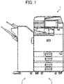
- FIG. 1 is a diagram illustrating an overall configuration of the image forming system 1.
- the image forming system 1 has a function of forming an image on a sheet and executing post-processing on the sheet on which the image is formed. As illustrated in FIG. 1 , the image forming system 1 includes an image forming apparatus 2 and a post-processing apparatus 3.
- the image forming apparatus 2 forms an image on a sheet (medium) and ejects the sheet having the image to the post-processing apparatus 3.
- the image forming apparatus 2 mainly includes a tray in which a sheet (sheets) is contained, a medium conveyor that conveys the sheet contained in the tray, and an image forming device that forms an image on the sheet conveyed by the medium conveyor.
- the image forming device may be an inkjet image forming device in which an image is formed with ink or an electrophotographic image forming device in which an image is formed with toner. Since the image forming apparatus 2 has a typical configuration, a detailed description of configuration and functions of the image forming apparatus 2 is omitted.
- FIG. 2 is a diagram illustrating an internal configuration of the post-processing apparatus 3 included in the image forming system 1 of FIG. 1 .
- the post-processing apparatus 3 executes post-processing on the sheet on which the image is formed by the image forming apparatus 2.
- the post-processing executed by the post-processing apparatus 3 according to the present embodiment includes saddle stitching in which sheets each having an image are bound.
- the bound sheets are collectively referred to as a "sheet bundle Mb".
- the post-processing apparatus 3 executes an edge stitching process for binding the edge of the sheet bundle Mb and a saddle stitching process for binding the center of the sheet bundle Mb.
- the post-processing apparatus 3 includes conveyance roller pairs 10 to 19 and a switching claw 20.
- the conveyance roller pairs 10 to 19 convey the sheet fed from the image forming apparatus 2 so that the sheet travels inside the post-processing apparatus 3. More specifically, the conveyance roller pairs 10 to 13 convey the sheet along a first conveyance passage Ph1. The conveyance roller pairs 14 and 15 convey the sheet along a second conveyance passage Ph2. Further, the conveyance roller pairs 16 to 19 convey the sheet along a third conveyance passage Ph3.
- the first conveyance passage Ph1 is a passage extending from a sheet supporting port from the image forming apparatus 2 to a sheet ejection tray 21.
- the second conveyance passage Ph2 is a passage branching from the first conveyance passage Ph1 between the conveyance roller pairs 11 and 14 in the conveyance direction of the sheet and extending to a sheet ejection tray 26 via the internal sheet tray 22.
- the third conveyance passage Ph3 is a passage branching from the first conveyance passage Ph1 between the conveyance roller pairs 11 and 14 in the conveyance direction of the sheet and extending to a sheet ejection tray 30.
- the switching claw 20 is disposed at a branching position of the first conveyance passage Ph1 and the second conveyance passage Ph2.
- the switching claw 20 is switchable between a first position where the sheet is ejected to the sheet ejection tray 21 through the first conveyance passage Ph1 and a second position where the sheet conveyed through the first conveyance passage Ph1 is guided to the second conveyance passage Ph2.
- the conveyance roller pair 14 is rotated in the reverse direction so that the sheet is guided to the third conveyance passage Ph3.
- the post-processing apparatus 3 further includes a plurality of sensors that detects the positions of the sheet in the first conveyance passage Ph1, the second conveyance passage Ph2, and the third conveyance passage Ph3. Each of the plurality of sensors is indicated by a black triangle mark in FIG. 2 .
- the post-processing apparatus 3 further includes a sheet ejection tray 21.
- the sheet ejection tray 21 supports the sheet ejected through the first conveyance passage Ph1.
- the sheet ejection tray 21 receives a sheet (or sheets) on which the post-processing is not executed, among the sheets fed from the image forming apparatus 2. In other words, a sheet (or sheets) on which the post-processing is not executed is ejected to the sheet ejection tray 21.
- the post-processing apparatus 3 includes the internal sheet tray 22, an end fence 23, side fences 24, a binding unit 25, and a sheet ejection tray 26.
- the internal sheet tray 22, the end fence 23, the side fences 24, and the binding unit 25 are included in an edge stitching device (post-processing device) that executes an edge stitching process on the sheet conveyed in the second conveyance passage Ph2.
- the sheet ejection tray 26 receives a bundle of sheets (sheet bundle Mb) on which the edge stitching process is executed by the edge stitching device.
- a bundle of sheets (sheet bundle Mb) on which the edge stitching process is executed by the end stitching device is ejected to the sheet ejection tray 26.
- the internal sheet tray 22 temporarily supports the sheet bundles sequentially conveyed through the second conveyance passage Ph2.
- the end fence 23 aligns the position of the sheet bundle Mb supported by the internal sheet tray 22 in the conveyance direction of the sheet bundle Mb.
- the side fences 24 align the position of the sheet bundle Mb supported by the internal sheet tray 22 in the width direction of the sheet bundle Mb orthogonal to the conveyance direction of the sheet bundle Mb.
- the binding unit 25 binds an end of the sheet bundle Mb aligned by the end fence 23 and the side fences 24. Then, the conveyance roller pair 15 (sheet ejection unit) ejects the sheet bundle Mb subjected to the edge stitching process by the edge stitching device to the sheet ejection tray 26.
- the post-processing apparatus 3 further includes an end fence 27, a binding unit 28, a sheet folding blade 29, and a sheet ejection tray 30.
- the end fence 27, the binding unit 28, and the sheet folding blade 29 are included in a saddle stitching device (post-processing device) that executes a saddle stitching process on sheets conveyed through the third conveyance passage Ph3.
- the sheet ejection tray 30 receives a bundle of sheets (sheet bundle Mb) on which the saddle stitching process is executed by the saddle stitching device.
- a bundle of sheets (sheet bundle Mb) on which the saddle stitching process is executed by the saddle stitching device is ejected to the sheet ejection tray 30.
- the end fence 27 aligns the positions of the sheet bundle sequentially conveyed through the third conveyance passage Ph3 in the conveyance direction of the sheet bundle. Further, the end fence 27 is movable between a binding position where the center of the sheet bundle Mb faces the binding unit 28 and a folding position where the center of the sheet bundle Mb faces the sheet folding blade 29.
- the binding unit 28 binds the center of the sheet bundle Mb aligned by the end fence 27 at the binding position.
- the sheet folding blade 29 folds the sheet bundle Mb in half while the sheet bundle Mb is supported by the end fence 27 at the folding position, and then causes the conveyance roller pair 18 to nip the sheet bundle Mb.
- the conveyance roller pairs 18 and 19 (sheet ejection unit) eject the sheet bundle Mb subjected to the saddle stitching process by the binding unit 28 to the sheet ejection tray 30.
- FIGS. 3A and 3B are enlarged views of the sheet ejection tray 30 included in the post-processing apparatus 3 of FIG. 2 .
- the sheet ejection tray 30 is changeable to an appropriate position in accordance with the number of copies of the sheet bundles Mb that has been subjected to the saddle stitching process and ejected to the outside of the post-processing apparatus 3.
- the number of copies of the sheet bundles Mb corresponds to the number of copies that are simultaneously stacked on the sheet ejection tray 30.
- the sheet ejection tray 30 includes a main tray 31, a movable tray 32, a distal end fence 33, and a stacking amount sensor 34.
- the main tray 31 is disposed at a position capable of supporting the sheet bundle Mb ejected by the conveyance roller pair 19. More specifically, the main tray 31 is disposed below the conveyance roller pair 19 to protrude outward from the housing of the post-processing apparatus 3.
- the upper face of the main tray 31 is a sloped face that is inclined downward in the ejection direction (toward the left side of FIG. 2 ) of the sheet bundle Mb ejected by the conveyance roller pair 19. Further, the main tray 31 supports the movable tray 32 and the distal end fence 33.
- the movable tray 32 is provided on the root end of the main tray 31 (upstream side in the discharge direction) and is rotatably supported with respect to the main tray 31 via a support shaft 35.
- the support shaft 35 extends in the width direction of the sheet bundle Mb that is orthogonal to the ejection direction of the sheet bundle Mb and the vertical direction of the post-processing apparatus 3. Further, the support shaft 35 is attached to a distal end of the movable tray 32 (i.e., the downstream end in the ejection direction of the sheet bundle Mb).
- the movable tray 32 is rotatable with the downstream end in the ejection direction of the sheet bundle Mb as a rotation base end and the upstream end in the ejection direction of the sheet bundle Mb as a rotation distal end. More specifically, the movable tray 32 rotates between a stacking position illustrated in FIG. 3A and an ejection position illustrated in FIG. 3B .
- the stacking position is taken by the movable tray 32 when the sheet bundle Mb ejected by the conveyance roller pair 19 is stacked on the movable tray 32 and is a position at which the sheet bundle Mb maintains for not sliding down due to the inclination of the main tray 31. Therefore, the upper face of the movable tray 32 is horizontal in the stacking position.
- the ejection position is a position taken by the movable tray 32 when the sheet bundle Mb ejected by the conveyance roller pair 19 is ejected along the inclination of the upper face of the main tray 31. Therefore, the upper face of the movable tray 32 is inclined downward along the upper face of the main tray 31 in the ejection position.
- the movable tray 32 changes the position from the stacking position to the ejection position by rotating so that the downstream end in the ejection direction of the sheet bundle Mb springs up.
- the angle of inclination of the upper face of the movable tray 32 in the ejection position is set to be equal to or greater than the angle of inclination of the upper face of the main tray 31.
- the movable tray 32 is supported by the main tray 31 to be slidable along the inclination direction of the main tray 31. More specifically, as illustrated in FIG. 3A , a guide groove 36 extending along the inclination direction of the main tray 31 is formed on the side face of the main tray 31.
- the guide groove 36 supports the support shaft 35 rotatably in the axial direction of the main tray 31 and slidably in the inclination direction of the main tray 31.
- the movable tray 32 in the ejection position slides toward the root end of the main tray 31 as indicated by arrow "a" in FIG. 3B , a gap is formed between the upper face of the main tray 31 and the upper face of the movable tray 32.
- the movable tray 32 is rotatable between the ejection position and the stacking position.
- the movable tray 32 in the ejection position slides to the distal end of the main tray 31 in the direction indicated by arrow "b" in FIG. 3B , so that the upper face of the main tray 31 and the upper face of the movable tray 32 are continuously extended as a single face.
- no gap is formed between the upper face of the main tray 31 and the upper face of the movable tray 32.
- the distal end fence 33 is disposed downstream from the movable tray 32 in the ejection direction of the sheet bundle Mb, in other words, on the distal end of the main tray 31.
- the distal end fence 33 is rotatably supported by the main tray 31 via a support shaft 37.
- the support shaft 37 extends in the width direction of the sheet bundle Mb that is orthogonal to the ejection direction of the sheet bundle Mb and the vertical direction of the post-processing apparatus 3. In other words, the support shaft 37 extends in a direction parallel to the axis of the support shaft 35.
- the distal end fence 33 pivots between a protruding position illustrated in FIG. 3A and a retraction position illustrated in FIG. 3B .
- the protruding position is a position at which the distal end fence 33 is protruded upward from the upper face of the main tray 31 and prevents the sheet bundle Mb from being ejected from the main tray 31. Therefore, the protruding position is a position taken by the distal end fence 33 to prevent the sheet bundle Mb from coming off from the main tray 31 when the sheet bundle Mb moves along the upper face of the main tray 31, in other words, when the sheet bundle Mb slides down the sloped face of the main tray 31 that is inclined downward. In the retraction position, the sheet bundle Mb is allowed to be ejected along the upper face of the main tray 31.
- the retraction position is also a position at which the distal end fence 33 is retracted from the upper face of the main tray 31 and the sheet bundle Mb is ejected from the main tray 31. More specifically, the retraction position is a position at which the distal end fence 33 is retracted below the upper face of the main tray 31.
- the distal end fence 33 may change the position in conjunction with movement of the movable tray 32. More specifically, as illustrated in FIG. 3A , the distal end fence 33 may be brought to the protruding position in conjunction with the movable tray 32 changing to the stacking position. Further, as illustrated in FIG. 3B , the distal end fence 33 may be brought into the retraction position in conjunction with the movable tray 32 changing to the ejection position.
- the sheet ejection tray 30 may include a transmission mechanism (for example, gear and belt) that transmits the rotation (change of position) of the movable tray 32, to the distal end fence 33.
- the sheet bundle Mb ejected by the conveyance roller pair 19 is stacked onto the movable tray 32. Even when the sheet bundle Mb slides from the movable tray 32 to the main tray 31, the distal end fence 33 prevents the sheet bundle Mb from falling from the sheet ejection tray 30.
- the sheet bundle Mb ejected by the conveyance roller pair 19 or stacked on the movable tray 32 in the stacking position slides down along the upper face of the sloped face of the movable tray 32 and the upper face of the main tray 31 to be ejected from the sheet ejection tray 30.
- the stacking amount sensor 34 detects the amount (number) of sheet bundles Mb stacked on the movable tray 32 at the stacking position.
- the stacking amount sensor 34 is rotatably supported by the housing of the post-processing apparatus 3 via a support shaft 38. Further, the stacking amount sensor 34 contacts the uppermost sheet bundle Mb stacked on the movable tray 32. That is, the angle of the stacking amount sensor 34 changes in accordance with the amount of the sheet bundle Mb stacked on the movable tray 32.
- the stacking amount sensor 34 outputs a stacking amount signal corresponding to the current angle, to a controller 100 (see FIG. 4 ). Note that the specific structure of the stacking amount sensor 34 is not limited to the example described above.
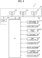
- FIG. 4 is a schematic block diagram illustrating a hardware configuration of the post-processing apparatus 3 of FIG. 2 .
- the post-processing apparatus 3 includes a central processing unit (CPU) 101, a random access memory (RAM) 102, a read only memory (ROM) 103, a hard disk drive (HDD) 104, and an interface (I/F) 105.
- the CPU 101, the RAM 102, the ROM 103, the HDD 104, and the I/F 105 are connected each other via a common bus 109.
- the CPU 101 is an arithmetic unit and controls the overall operation of the post-processing apparatus 3.
- the RAM 102 is a volatile storage medium that allows data to be read and written at high speed.
- the CPU 101 uses the RAM 102 as a work area for data processing.
- the ROM 103 is a read-only non-volatile storage medium that stores programs such as firmware.
- the HDD 104 is a non-volatile storage medium that allows data to be read and written and has a relatively large storage capacity.
- the HDD 104 stores, e.g., an operating system (OS), various control programs, and application programs.
- OS operating system
- the post-processing apparatus 3 processes, by an arithmetic function of the CPU 101, e.g., a control program stored in the ROM 103 and an information processing program (or application program) loaded into the RAM 102 from a storage medium such as the HDD 104. Such processing configures a software controller including various functional modules of the post-processing apparatus 3.
- the software controller thus configured cooperates with hardware resources of the post-processing apparatus 3 construct functional blocks to implement functions of the post-processing apparatus 3.
- the CPU 101, the RAM 102, the ROM 103, and the HDD 104 implement the controller 100 to control the operation of the post-processing apparatus 3.
- the I/F 105 is an interface that connects the conveyance roller pairs 10 to 19, the switching claw 20, the binding units 25 and 28, the end fence 27, the sheet folding blade 29, the movable tray 32, the distal end fence 33, the stacking amount sensor 34, and a control panel 110, to the common bus 109.
- the controller 100 drives a motor through the I/F 105 to operate the conveyance roller pairs 10 to 19, the switching claw 20, the binding units 25 and 28, the end fence 27, the sheet folding blade 29, the movable tray 32, and the distal end fence 33.
- the controller 100 controls the operations of the conveyance roller pairs 10 to 19, the switching claw 20, the binding units 25 and 28, the end fence 27, and the sheet folding blade 29 to execute the post-processing on the sheet bundle Mb on which images are formed by the image forming apparatus 2.
- the controller 100 controls the operations of the movable tray 32 and the distal end fence 33 based on the stacking amount signal output from the stacking amount sensor 34. By so doing, the sheet bundle Mb subjected to the saddle stitching process is stacked on the sheet ejection tray 30 or is ejected from the sheet ejection tray 30.
- the controller 100 may drive a motor to rotate the movable tray 32 and the distal end fence 33.
- the sheet ejection tray 30 may include an operation member that manually changes the positions of the movable tray 32 and the distal end fence 33.
- a user may operate the operation member to rotate the movable tray 32 and the distal end fence 33.
- a speed reduction mechanism may be provided between the operation member and each of the movable tray 32 and the distal end fence 33.
- the control panel 110 includes an operation unit that receives an operation instruction from the user and a display (notification unit) that notifies the user of information.
- the operation unit includes, for example, hard keys and a touch panel superimposed on a display.
- the control panel 110 acquires information from the user through the operation unit and provides the information to the user through the display.
- a specific example of the notification unit is not limited to the display and may be an LED lamp or a speaker.
- FIG. 5 is a flowchart of a binding process.
- the controller 100 starts the binding process illustrated in FIG. 5 , for example, at a timing when an instruction to execute the binding process (hereinafter, referred to as a "binding command") is acquired from the image forming apparatus 2.
- the binding command includes, for example, the number of sheets included in the sheet bundle Mb (hereinafter referred to as a "given number of sheets”) and the number of sheet bundles Mb on which the binding process is executed (hereinafter referred to as a "requested number of copies").
- the post-processing apparatus 3 is capable of selecting one of a plurality of binding modes.
- the binding modes include an edge stitching mode in which the edge stitching process is executed and a saddle stitching mode in which the saddle stitching process is executed.
- the post-processing apparatus 3 selects one of a plurality of ejection modes.
- the ejection modes include a collective ejection mode in which a plurality of sheet bundles Mb are stacked on the movable tray 32 and then collectively ejected, and a sequential ejection mode in which a sheet bundle Mb is ejected each time the conveyance roller pair 19 ejects the sheet bundle Mb.
- the binding modes and the ejection modes may be selected by the user through the control panel 110 or may be included in the binding command.
- the controller 100 determines the selected binding mode (step S501).
- the controller 100 executes the edge stitching process (step S502).
- the edge stitching process is a process in which an end of the sheet bundle Mb is bound by the edge stitching device. A detailed description of the edge stitching process is omitted.
- step S501 determines whether a collective ejection mode or a sequential ejection mode is selected (step S503).
- the controller 100 determines that the collective ejection mode is selected (YES in step S503)
- the controller 100 executes the saddle stitching and collective ejection process in FIG. 6 (step S504).
- the controller 100 determines that the sequential ejection mode is selected (NO in step S503)
- the controller 100 executes the saddle stitching and sequential ejection process in FIG. 7 (step S505).
- FIG. 6 is a flowchart of the saddle stitching and collective ejection process.
- the saddle stitching and collective ejection process is a process of stacking the sheet bundle Mb stitched by the saddle stitching device on the movable tray 32 and collectively ejecting the sheet bundle Mb at a timing when the number of sheet bundles Mb stacked on the movable tray 32 reaches the threshold value. Note that, at the start of the saddle stitching and collective ejection process, the end fence 27 is at the binding position, the movable tray 32 is at the stacking position, and the distal end fence 33 is at the protruding position.
- the controller 100 causes the conveyance roller pairs 10, 11, 14, 16, and 17 to rotate, so that the sheet on which the image is formed by the image forming apparatus 2 on the end fence 27 (step S601).
- the controller 100 determines whether or not the number of sheets on the end fence 27 reaches the given number of sheets indicated by the binding command (step S602).
- step S602 When the controller 100 determines that the number of sheets on the end fence 27 does not reach the given number of sheets (NO in step S602), the controller 100 executes the process of step S601 again. On the other hand, when the controller 100 determines that the number of sheets on the end fence 27 reaches the given number of sheets (YES in step S602), the controller 100 causes the sheet bundle Mb on the end fence 27 to be folded in half, and then causes the sheet bundle Mb to be ejected to the movable tray 32 at the stacking position (step S603).
- the controller 100 causes the binding unit 28 to bind the center of the sheet bundle Mb on the end fence 27 at the binding position.
- the controller 100 causes the end fence 27 to move to the folding position.
- the controller 100 causes the sheet folding blade 29 to fold the sheet bundle Mb on the end fence 27 at the folding position in half, and then causes the conveyance roller pair 18 to nip the sheet bundle Mb.
- the controller 100 causes the conveyance roller pairs 18 and 19 to be rotated to eject the sheet bundle Mb to the movable tray 32 at the stacking position. Further, the controller 100 causes the end fence 27 and the sheet folding blade 29 to return to the original positions.
- the controller 100 determines whether or not the sheet bundle Mb are fully stacked on the movable tray 32 at the stacking position based on the stacking amount signal output from the stacking amount sensor 34 (step S604).
- the state in which the sheet bundles Mb are fully stacked on the movable tray 32 at the stacking position is referred to as a "fully stacked state.”
- the controller 100 determines whether or not the number of sheet bundles Mb detected by the stacking amount sensor 34 reaches a threshold value. Then, when the controller 100 determines that the number of sheet bundles Mb stacked on the movable tray 32 at the stacking position is smaller than the threshold value (NO in step S604), the controller 100 executes the processing after step S601 again.
- step S604 when the controller 100 determines that the number of sheet bundles Mb stacked on the movable tray 32 at the stacking position reaches the threshold value (YES in step S604), the controller 100 causes the movable tray 32 to change to the ejection position and causes the distal end fence 33 to change to the retraction position (step S605). As the controller 100 executes the processing of step S605, the sheet bundles Mb fully stacked on the movable tray 32 are ejected from the sheet ejection tray 30 along the upper face of the movable tray 32 and the upper face of the main tray 31.
- step S605 the controller 100 determines whether or not the sheet bundle Mb is ejected from the movable tray 32, in other words, the full stacked state is cancelled, based on the stacking amount signal output from the stacking amount sensor 34 (step S606).
- the controller 100 determines that the full stacked state of the movable tray 32 is not cancelled (NO in step S606), the controller 100 causes the display to display a message prompting removal of the sheet bundles Mb on the movable tray 32 (step S607), and then repeats step S606 until the controller 100 determines that the full stacked state of the movable tray 32 is cancelled.
- the controller 100 continues to display the message until the full stacked state is cancelled.
- the notification method is not limited to displaying a message and may be lighting of a light-emitting diode (LED) lamp or an output of a guide sound through a speaker. Then, a user received this notification may operate the operation unit to forcibly change the position of the movable tray 32 or may manually remove the sheet bundle Mb from the movable tray 32.
- step S606 when the controller 100 determines that the full stacked state of the movable tray 32 is cancelled (YES in step S606), the controller 100 causes the movable tray 32 to change to the stacking position and causes the distal end fence 33 to change to the protruding position (step S608).
- step S609 the controller 100 determines whether or not the number of sheet bundles Mb reaches a requested number of copies indicated by the binding command (step S609).
- the controller 100 executes the processing of step S601 again.
- the controller 100 determines that the number of sheet bundles Mb reaches the requested number of copies (YES in S609), the controller 100 ends the saddle stitching and collective ejection process.
- FIG. 7 is a flowchart of the saddle stitching and sequential discharge process.
- the saddle stitching and sequential discharge process is a process of sequentially ejecting the sheet bundles Mb stitched by the saddle stitching device from the sheet ejection tray 30 without stacking the sheet bundles Mb on the movable tray 32.
- the end fence 27 is at the binding position
- the movable tray 32 is at the stacking position
- the distal end fence 33 is at the protruding position.
- a detailed description of the features of the saddle stitching and sequential ejection process common to the saddle stitching and collective ejection process is omitted and a description of the features of the saddle stitching and sequential ejection process different from the features of the saddle stitching and collective ejection process is mainly described.
- a main difference between the saddle stitching and collective ejection process and the saddle stitching and sequential ejection process is a timing at which the position of the movable tray 32 and the position of the distal end fence 33 are changed.
- the controller 100 causes the movable tray 32 to change to the ejection position and causes the distal end fence 33 to change to the retraction position (S701).
- the processing of step S701 of the flowchart in FIG. 7 is common to the processing of step S605 of the flowchart in FIG. 6 .
- the controller 100 executes the saddle stitching process on the sheet bundle Mb to fold the sheet bundle Mb in half, and then cause the sheet bundle Mb to be ejected to the movable tray 32 (steps S702 to S704).
- the processing of steps S702 to S704 of the flowchart in FIG. 7 is common to the processing of steps S601 to S603 of the flowchart in FIG. 6 .
- the sheet bundle Mb ejected to the movable tray 32 in step S704 is supposed to slide down on the upper face of the movable tray 32 and the upper face of the main tray 31 at the ejection position to be ejected from the sheet ejection tray 30.
- the sheet bundle Mb ejected by the conveyance roller pair 19 is caught by any obstacle and fails to slide down on the movable tray 32.
- step S704 the controller 100 determines whether or not the movable tray 32 is fully stacked with the sheet bundles Mb based on the stacking amount signal output from the stacking amount sensor 34 (step S705).
- the controller 100 determines that the movable tray 32 is fully stacked with the sheet bundles Mb (YES in step S705)
- the controller 100 causes the display to display a message prompting removal of the sheet bundles Mb on the movable tray 32 (step S706), and then repeats step S705 until the controller 100 determines that the movable tray 32 is not fully stacked with the sheet bundles Mb.
- step S707 is common to the processing of steps S606 to S607 of the flowchart in FIG. 6 .
- the controller 100 determines whether or not the movable tray 32 is not fully stacked with the sheet bundles Mb (NO in step S705), the controller 100 determines whether or not the number of sheet bundles Mb reaches a requested number of copies indicated by the binding command (step S707).
- the processing of step S707 of the flowchart in FIG. 7 is common to the processing of step S609 of the flowchart in FIG. 6 .
- step S702 When the controller 100 determines that the number of sheet bundles Mb does not reach the requested number of copies (NO in S707), the controller 100 executes the processing of step S702 and the following steps again. On the other hand, when the controller 100 determines that the number of sheet bundles Mb stacked on the movable tray 32 reaches the requested number of copies (YES in step S707), the controller 100 causes the movable tray 32 to change to the stacking position and causes the distal end fence 33 to change to the protruding position (step S708).
- the processing of step S708 of the flowchart in FIG. 7 is common to the processing of step S608 of the flowchart in FIG. 6 .
- the sheet bundle Mb is ejected at an appropriate timing while obtaining the stacking amount when the sheet bundle Mb is desired to be stacked.
- the upper face of the movable tray 32 is horizontal when the movable tray 32 is at the stacking position and is inclined downward along the upper face of the main tray 31 when the movable tray 32 is at the ejection position.
- the movable tray 32 is slidable so that the upper face of the movable tray 32 at the ejection position and the upper face of the main tray 31 are continuously extended as a single face. Accordingly, when the position of the movable tray 32 is changed from the stacking position to the ejection position, the sheet bundle Mb is prevented from being caught in the gap between the movable tray 32 and the main tray 31 and failing to be ejected.
- the operation member in which a user manually changes the position of the movable tray 32 achieves the position change of the movable tray 32 with a simple configuration.
- the post-processing apparatus 3 may include the function of the controller 100 changing the position of the movable tray 32, the function of the user manually changing the position of the movable tray 32, or both.
- the movable tray 32 when the movable tray 32 is fully stacked, the movable tray 32 changes to the ejection position. By so doing, the stacking amount of the sheet bundles Mb on the movable tray 32 is obtained and the sheet bundle Mb is ejected at an appropriate timing.
- the sheet bundle Mb to be ejected by the conveyance roller pair 19 may be sequentially ejected without being stacked on the movable tray 32.
- the sheet ejection tray 30 supports the sheet bundle Mb to be ejected from the saddle stitching device.
- the sheet ejection tray 30 may support the sheet bundle Mb to be ejected from the edge stitching device or may support sheets subjected to another post-processing such as a punching process in which multiple through holes are formed in the sheet.
- control method described above may be implemented by, for example, a program. That is, the control method may be executed by causing an arithmetic device, a storage device, an input device, an output device, and a control device to operate in cooperation with each other based on a program.
- the program may be written in, for example, a storage device or a storage medium and distributed, or may be distributed through, for example, an electric communication line.
Landscapes
- Engineering & Computer Science (AREA)
- Mechanical Engineering (AREA)
- Textile Engineering (AREA)
- Pile Receivers (AREA)
- Folding Of Thin Sheet-Like Materials, Special Discharging Devices, And Others (AREA)
Abstract

Description
- Embodiments of the present disclosure relate to a post-processing apparatus and an image forming system incorporating the post-processing apparatus.
- In the related art, post-processing apparatuses are known to execute post-processing on a sheet on which an image is formed by an image forming apparatus. For example, the post-processing executed by a post-processing apparatus includes saddle stitching in which a plurality of bundled sheets (hereinafter referred to as a "sheet bundle") are bound at the center.
- Such a post-processing apparatus may continuously perform saddle stitching on a large number of sheet bundles. To perform saddle stitching continuously, some post-processing apparatuses are provided with a sheet ejection tray that is inclined, so that sheet bundles are continuously ejected to fall from the sheet ejection tray (for example, see
Japanese Unexamined Patent Application Publication No. 2012-250844 - At the same time, some post-processing apparatuses may be used to perform the saddle stitching on a small number of sheet bundles and cause the sheet bundle to be stacked on a sheet ejection tray. However, when the sheet bundles are to be stacked on a tray after the post-processing, such a sheet ejection tray that is constantly inclined as described above cannot stack a large number of sheet bundles.
- In view of the above-described disadvantages, an object of the present disclosure is to provide a post-processing apparatus including a sheet ejection tray that is changeable to an appropriate position in accordance with the number of copies of recording media on which post-processing is executed.
- Embodiments of the present disclosure described herein provide a novel post-processing apparatus including a post-processing device, an ejection device, and an ejection tray. The post-processing device executes post-processing on a medium on which an image is formed by an image forming apparatus. The ejection device ejects the medium on which the post-processing is executed by the post-processing device. The ejection tray holds the medium ejected by the ejection device. The ejection tray includes a main tray having an upper face inclined downward in an ejection direction, and a movable tray being rotatably supported by the main tray between a stacking position at which the medium ejected by the ejection device remains stacked on the upper face of the main tray and an ejection position at which the medium ejected by the ejection device slides along the upper face of the main tray.
- Further, embodiments of the present disclosure described herein provide an image forming system including an image forming apparatus that forms an image on a medium, and the above-described post-processing apparatus that executes the post-processing on the medium on which the image is formed by the image forming apparatus.
- According to the present disclosure, a post-processing apparatus and an image forming system including the post-processing apparatus are provided with a sheet ejection tray that is changeable to an appropriate position in accordance with the number of copies of recording media on which post-processing is executed.
- Exemplary embodiments of this disclosure will be described in detail based on the following figures, wherein:
-
FIG. 1 is a diagram illustrating an overall configuration of an image forming system according to an embodiment of the present disclosure; -
FIG. 2 is a diagram illustrating an internal configuration of a post-processing apparatus included in the image forming system ofFIG. 1 ; -
FIGS. 3A and 3B are enlarged views of a sheet ejection tray included in the post-processing apparatus ofFIG. 2 ; -
FIG. 4 is a schematic block diagram illustrating a hardware configuration of the post-processing apparatus ofFIG. 2 ; -
FIG. 5 is a flowchart of a binding process; -
FIG. 6 is a flowchart of a saddle stitching and collective ejection process; and -
FIG. 7 is a flowchart of a saddle stitching and sequential ejection process. - The accompanying drawings are intended to depict embodiments of the present disclosure and should not be interpreted to limit the scope thereof. The accompanying drawings are not to be considered as drawn to scale unless explicitly noted.
- It will be understood that if an element or layer is referred to as being "on," "against," "connected to" or "coupled to" another element or layer, then it can be directly on, against, connected or coupled to the other element or layer, or intervening elements or layers may be present. In contrast, if an element is referred to as being "directly on," "directly connected to" or "directly coupled to" another element or layer, then there are no intervening elements or layers present. Like numbers referred to like elements throughout. As used herein, the term "and/or" includes any and all combinations of one or more of the associated listed items.
- Spatially relative terms, such as "beneath," "below," "lower," "above," "upper" and the like may be used herein for ease of description to describe one element or feature's relationship to another element(s) or feature(s) as illustrated in the figures. It will be understood that the spatially relative terms are intended to encompass different orientations of the device in use or operation in addition to the orientation depicted in the figures. For example, if the device in the figures is turned over, elements describes as "below" or "beneath" other elements or features would then be oriented "above" the other elements or features. Thus, term such as "below" can encompass both an orientation of above and below. The device may be otherwise oriented (rotated 90 degrees or at other orientations) and the spatially relative descriptors herein interpreted accordingly.
- The terminology used herein is for describing particular embodiments and examples and is not intended to be limiting of exemplary embodiments of this disclosure. As used herein, the singular forms "a," "an," and "the" are intended to include the plural forms as well, unless the context clearly indicates otherwise. It will be further understood that the terms "includes" and/or "including," when used in this specification, specify the presence of stated features, integers, steps, operations, elements, and/or components, but do not preclude the presence or addition of one or more other features, integers, steps, operations, elements, components, and/or groups thereof.
- Referring now to the drawings, embodiments of the present disclosure are described below. In the drawings for explaining the following embodiments, the same reference codes are allocated to elements (members or components) having the same function or shape and redundant descriptions thereof are omitted below.
- Next, a description is given of a configuration and functions of a post-processing apparatus and an image forming apparatus, according to an embodiment of the present disclosure, with reference to drawings. Note that identical parts or equivalents are given identical reference numerals and redundant descriptions are summarized or omitted accordingly.
- Embodiments of the present disclosure are described below with reference to the attached drawings.
- Hereinafter, a description is given of an
image forming system 1 according to an embodiment of the present disclosure, with reference to the drawings. -
FIG. 1 is a diagram illustrating an overall configuration of theimage forming system 1. - The
image forming system 1 has a function of forming an image on a sheet and executing post-processing on the sheet on which the image is formed. As illustrated inFIG. 1 , theimage forming system 1 includes animage forming apparatus 2 and apost-processing apparatus 3. - The
image forming apparatus 2 forms an image on a sheet (medium) and ejects the sheet having the image to thepost-processing apparatus 3. Theimage forming apparatus 2 mainly includes a tray in which a sheet (sheets) is contained, a medium conveyor that conveys the sheet contained in the tray, and an image forming device that forms an image on the sheet conveyed by the medium conveyor. The image forming device may be an inkjet image forming device in which an image is formed with ink or an electrophotographic image forming device in which an image is formed with toner. Since theimage forming apparatus 2 has a typical configuration, a detailed description of configuration and functions of theimage forming apparatus 2 is omitted. -
FIG. 2 is a diagram illustrating an internal configuration of thepost-processing apparatus 3 included in theimage forming system 1 ofFIG. 1 . - The
post-processing apparatus 3 executes post-processing on the sheet on which the image is formed by theimage forming apparatus 2. For example, the post-processing executed by thepost-processing apparatus 3 according to the present embodiment includes saddle stitching in which sheets each having an image are bound. Hereinafter, the bound sheets are collectively referred to as a "sheet bundle Mb". More specifically, thepost-processing apparatus 3 executes an edge stitching process for binding the edge of the sheet bundle Mb and a saddle stitching process for binding the center of the sheet bundle Mb. - The
post-processing apparatus 3 includesconveyance roller pairs 10 to 19 and aswitching claw 20. The conveyance roller pairs 10 to 19 convey the sheet fed from theimage forming apparatus 2 so that the sheet travels inside thepost-processing apparatus 3. More specifically, the conveyance roller pairs 10 to 13 convey the sheet along a first conveyance passage Ph1. The conveyance roller pairs 14 and 15 convey the sheet along a second conveyance passage Ph2. Further, the conveyance roller pairs 16 to 19 convey the sheet along a third conveyance passage Ph3. - The first conveyance passage Ph1 is a passage extending from a sheet supporting port from the
image forming apparatus 2 to asheet ejection tray 21. The second conveyance passage Ph2 is a passage branching from the first conveyance passage Ph1 between the conveyance roller pairs 11 and 14 in the conveyance direction of the sheet and extending to asheet ejection tray 26 via theinternal sheet tray 22. The third conveyance passage Ph3 is a passage branching from the first conveyance passage Ph1 between the conveyance roller pairs 11 and 14 in the conveyance direction of the sheet and extending to asheet ejection tray 30. - The switching
claw 20 is disposed at a branching position of the first conveyance passage Ph1 and the second conveyance passage Ph2. The switchingclaw 20 is switchable between a first position where the sheet is ejected to thesheet ejection tray 21 through the first conveyance passage Ph1 and a second position where the sheet conveyed through the first conveyance passage Ph1 is guided to the second conveyance passage Ph2. At the timing when the trailing end of the sheet entering the second conveyance passage Ph2 passes through theconveyance roller pair 11, theconveyance roller pair 14 is rotated in the reverse direction so that the sheet is guided to the third conveyance passage Ph3. Thepost-processing apparatus 3 further includes a plurality of sensors that detects the positions of the sheet in the first conveyance passage Ph1, the second conveyance passage Ph2, and the third conveyance passage Ph3. Each of the plurality of sensors is indicated by a black triangle mark inFIG. 2 . - The
post-processing apparatus 3 further includes asheet ejection tray 21. Thesheet ejection tray 21 supports the sheet ejected through the first conveyance passage Ph1. Thesheet ejection tray 21 receives a sheet (or sheets) on which the post-processing is not executed, among the sheets fed from theimage forming apparatus 2. In other words, a sheet (or sheets) on which the post-processing is not executed is ejected to thesheet ejection tray 21. - The
post-processing apparatus 3 includes theinternal sheet tray 22, anend fence 23,side fences 24, a binding unit 25, and asheet ejection tray 26. Theinternal sheet tray 22, theend fence 23, theside fences 24, and the binding unit 25 are included in an edge stitching device (post-processing device) that executes an edge stitching process on the sheet conveyed in the second conveyance passage Ph2. Among the sheets fed from theimage forming apparatus 2, thesheet ejection tray 26 receives a bundle of sheets (sheet bundle Mb) on which the edge stitching process is executed by the edge stitching device. In other words, a bundle of sheets (sheet bundle Mb) on which the edge stitching process is executed by the end stitching device is ejected to thesheet ejection tray 26. - The
internal sheet tray 22 temporarily supports the sheet bundles sequentially conveyed through the second conveyance passage Ph2. Theend fence 23 aligns the position of the sheet bundle Mb supported by theinternal sheet tray 22 in the conveyance direction of the sheet bundle Mb. Theside fences 24 align the position of the sheet bundle Mb supported by theinternal sheet tray 22 in the width direction of the sheet bundle Mb orthogonal to the conveyance direction of the sheet bundle Mb. The binding unit 25 binds an end of the sheet bundle Mb aligned by theend fence 23 and theside fences 24. Then, the conveyance roller pair 15 (sheet ejection unit) ejects the sheet bundle Mb subjected to the edge stitching process by the edge stitching device to thesheet ejection tray 26. - The
post-processing apparatus 3 further includes anend fence 27, a binding unit 28, asheet folding blade 29, and asheet ejection tray 30. Theend fence 27, the binding unit 28, and thesheet folding blade 29 are included in a saddle stitching device (post-processing device) that executes a saddle stitching process on sheets conveyed through the third conveyance passage Ph3. Among the sheets fed from theimage forming apparatus 2, thesheet ejection tray 30 receives a bundle of sheets (sheet bundle Mb) on which the saddle stitching process is executed by the saddle stitching device. In other words, a bundle of sheets (sheet bundle Mb) on which the saddle stitching process is executed by the saddle stitching device is ejected to thesheet ejection tray 30. - The
end fence 27 aligns the positions of the sheet bundle sequentially conveyed through the third conveyance passage Ph3 in the conveyance direction of the sheet bundle. Further, theend fence 27 is movable between a binding position where the center of the sheet bundle Mb faces the binding unit 28 and a folding position where the center of the sheet bundle Mb faces thesheet folding blade 29. The binding unit 28 binds the center of the sheet bundle Mb aligned by theend fence 27 at the binding position. Thesheet folding blade 29 folds the sheet bundle Mb in half while the sheet bundle Mb is supported by theend fence 27 at the folding position, and then causes theconveyance roller pair 18 to nip the sheet bundle Mb. The conveyance roller pairs 18 and 19 (sheet ejection unit) eject the sheet bundle Mb subjected to the saddle stitching process by the binding unit 28 to thesheet ejection tray 30. - Next, a description is given of a detailed configuration of the
sheet ejection tray 30, with reference toFIGS. 1 ,2 ,3A, and 3B . -
FIGS. 3A and 3B are enlarged views of thesheet ejection tray 30 included in thepost-processing apparatus 3 ofFIG. 2 . - The
sheet ejection tray 30 is changeable to an appropriate position in accordance with the number of copies of the sheet bundles Mb that has been subjected to the saddle stitching process and ejected to the outside of thepost-processing apparatus 3. The number of copies of the sheet bundles Mb corresponds to the number of copies that are simultaneously stacked on thesheet ejection tray 30. Thesheet ejection tray 30 includes amain tray 31, amovable tray 32, adistal end fence 33, and a stackingamount sensor 34. - The
main tray 31 is disposed at a position capable of supporting the sheet bundle Mb ejected by theconveyance roller pair 19. More specifically, themain tray 31 is disposed below theconveyance roller pair 19 to protrude outward from the housing of thepost-processing apparatus 3. The upper face of themain tray 31 is a sloped face that is inclined downward in the ejection direction (toward the left side ofFIG. 2 ) of the sheet bundle Mb ejected by theconveyance roller pair 19. Further, themain tray 31 supports themovable tray 32 and thedistal end fence 33. - The
movable tray 32 is provided on the root end of the main tray 31 (upstream side in the discharge direction) and is rotatably supported with respect to themain tray 31 via asupport shaft 35. Thesupport shaft 35 extends in the width direction of the sheet bundle Mb that is orthogonal to the ejection direction of the sheet bundle Mb and the vertical direction of thepost-processing apparatus 3. Further, thesupport shaft 35 is attached to a distal end of the movable tray 32 (i.e., the downstream end in the ejection direction of the sheet bundle Mb). That is, themovable tray 32 is rotatable with the downstream end in the ejection direction of the sheet bundle Mb as a rotation base end and the upstream end in the ejection direction of the sheet bundle Mb as a rotation distal end. More specifically, themovable tray 32 rotates between a stacking position illustrated inFIG. 3A and an ejection position illustrated inFIG. 3B . - The stacking position is taken by the
movable tray 32 when the sheet bundle Mb ejected by theconveyance roller pair 19 is stacked on themovable tray 32 and is a position at which the sheet bundle Mb maintains for not sliding down due to the inclination of themain tray 31. Therefore, the upper face of themovable tray 32 is horizontal in the stacking position. The ejection position is a position taken by themovable tray 32 when the sheet bundle Mb ejected by theconveyance roller pair 19 is ejected along the inclination of the upper face of themain tray 31. Therefore, the upper face of themovable tray 32 is inclined downward along the upper face of themain tray 31 in the ejection position. More specifically, themovable tray 32 changes the position from the stacking position to the ejection position by rotating so that the downstream end in the ejection direction of the sheet bundle Mb springs up. The angle of inclination of the upper face of themovable tray 32 in the ejection position is set to be equal to or greater than the angle of inclination of the upper face of themain tray 31. - Further, the
movable tray 32 is supported by themain tray 31 to be slidable along the inclination direction of themain tray 31. More specifically, as illustrated inFIG. 3A , aguide groove 36 extending along the inclination direction of themain tray 31 is formed on the side face of themain tray 31. Theguide groove 36 supports thesupport shaft 35 rotatably in the axial direction of themain tray 31 and slidably in the inclination direction of themain tray 31. - As the
movable tray 32 in the ejection position slides toward the root end of themain tray 31 as indicated by arrow "a" inFIG. 3B , a gap is formed between the upper face of themain tray 31 and the upper face of themovable tray 32. As a result, themovable tray 32 is rotatable between the ejection position and the stacking position. On the other hand, themovable tray 32 in the ejection position slides to the distal end of themain tray 31 in the direction indicated by arrow "b" inFIG. 3B , so that the upper face of themain tray 31 and the upper face of themovable tray 32 are continuously extended as a single face. As a result, no gap is formed between the upper face of themain tray 31 and the upper face of themovable tray 32. - The
distal end fence 33 is disposed downstream from themovable tray 32 in the ejection direction of the sheet bundle Mb, in other words, on the distal end of themain tray 31. Thedistal end fence 33 is rotatably supported by themain tray 31 via asupport shaft 37. Thesupport shaft 37 extends in the width direction of the sheet bundle Mb that is orthogonal to the ejection direction of the sheet bundle Mb and the vertical direction of thepost-processing apparatus 3. In other words, thesupport shaft 37 extends in a direction parallel to the axis of thesupport shaft 35. Thedistal end fence 33 pivots between a protruding position illustrated inFIG. 3A and a retraction position illustrated inFIG. 3B . - The protruding position is a position at which the
distal end fence 33 is protruded upward from the upper face of themain tray 31 and prevents the sheet bundle Mb from being ejected from themain tray 31. Therefore, the protruding position is a position taken by thedistal end fence 33 to prevent the sheet bundle Mb from coming off from themain tray 31 when the sheet bundle Mb moves along the upper face of themain tray 31, in other words, when the sheet bundle Mb slides down the sloped face of themain tray 31 that is inclined downward. In the retraction position, the sheet bundle Mb is allowed to be ejected along the upper face of themain tray 31. The retraction position is also a position at which thedistal end fence 33 is retracted from the upper face of themain tray 31 and the sheet bundle Mb is ejected from themain tray 31. More specifically, the retraction position is a position at which thedistal end fence 33 is retracted below the upper face of themain tray 31. - Further, the
distal end fence 33 may change the position in conjunction with movement of themovable tray 32. More specifically, as illustrated inFIG. 3A , thedistal end fence 33 may be brought to the protruding position in conjunction with themovable tray 32 changing to the stacking position. Further, as illustrated inFIG. 3B , thedistal end fence 33 may be brought into the retraction position in conjunction with themovable tray 32 changing to the ejection position. In this case, thesheet ejection tray 30 may include a transmission mechanism (for example, gear and belt) that transmits the rotation (change of position) of themovable tray 32, to thedistal end fence 33. - Thus, as illustrated in
FIG. 3A , when themovable tray 32 is in the stacking position and thedistal end fence 33 is in the protruding position, the sheet bundle Mb ejected by theconveyance roller pair 19 is stacked onto themovable tray 32. Even when the sheet bundle Mb slides from themovable tray 32 to themain tray 31, thedistal end fence 33 prevents the sheet bundle Mb from falling from thesheet ejection tray 30. - On the other hand, as illustrated in
FIG. 3B , when themovable tray 32 is at the ejection position and thedistal end fence 33 is in the retraction position, the sheet bundle Mb ejected by theconveyance roller pair 19 or stacked on themovable tray 32 in the stacking position slides down along the upper face of the sloped face of themovable tray 32 and the upper face of themain tray 31 to be ejected from thesheet ejection tray 30. - The stacking
amount sensor 34 detects the amount (number) of sheet bundles Mb stacked on themovable tray 32 at the stacking position. The stackingamount sensor 34 is rotatably supported by the housing of thepost-processing apparatus 3 via a support shaft 38. Further, the stackingamount sensor 34 contacts the uppermost sheet bundle Mb stacked on themovable tray 32. That is, the angle of the stackingamount sensor 34 changes in accordance with the amount of the sheet bundle Mb stacked on themovable tray 32. The stackingamount sensor 34 outputs a stacking amount signal corresponding to the current angle, to a controller 100 (seeFIG. 4 ). Note that the specific structure of the stackingamount sensor 34 is not limited to the example described above. -
FIG. 4 is a schematic block diagram illustrating a hardware configuration of thepost-processing apparatus 3 ofFIG. 2 . - As illustrated in
FIG. 4 , thepost-processing apparatus 3 includes a central processing unit (CPU) 101, a random access memory (RAM) 102, a read only memory (ROM) 103, a hard disk drive (HDD) 104, and an interface (I/F) 105. TheCPU 101, theRAM 102, theROM 103, the HDD 104, and the I/F 105 are connected each other via acommon bus 109. - The
CPU 101 is an arithmetic unit and controls the overall operation of thepost-processing apparatus 3. TheRAM 102 is a volatile storage medium that allows data to be read and written at high speed. TheCPU 101 uses theRAM 102 as a work area for data processing. TheROM 103 is a read-only non-volatile storage medium that stores programs such as firmware. The HDD 104 is a non-volatile storage medium that allows data to be read and written and has a relatively large storage capacity. The HDD 104 stores, e.g., an operating system (OS), various control programs, and application programs. - The
post-processing apparatus 3 processes, by an arithmetic function of theCPU 101, e.g., a control program stored in theROM 103 and an information processing program (or application program) loaded into theRAM 102 from a storage medium such as the HDD 104. Such processing configures a software controller including various functional modules of thepost-processing apparatus 3. The software controller thus configured cooperates with hardware resources of thepost-processing apparatus 3 construct functional blocks to implement functions of thepost-processing apparatus 3. Specifically, theCPU 101, theRAM 102, theROM 103, and the HDD 104 implement thecontroller 100 to control the operation of thepost-processing apparatus 3. - The I/
F 105 is an interface that connects the conveyance roller pairs 10 to 19, the switchingclaw 20, the binding units 25 and 28, theend fence 27, thesheet folding blade 29, themovable tray 32, thedistal end fence 33, the stackingamount sensor 34, and acontrol panel 110, to thecommon bus 109. Thecontroller 100 drives a motor through the I/F 105 to operate the conveyance roller pairs 10 to 19, the switchingclaw 20, the binding units 25 and 28, theend fence 27, thesheet folding blade 29, themovable tray 32, and thedistal end fence 33. - More specifically, the
controller 100 controls the operations of the conveyance roller pairs 10 to 19, the switchingclaw 20, the binding units 25 and 28, theend fence 27, and thesheet folding blade 29 to execute the post-processing on the sheet bundle Mb on which images are formed by theimage forming apparatus 2. In addition, thecontroller 100 controls the operations of themovable tray 32 and thedistal end fence 33 based on the stacking amount signal output from the stackingamount sensor 34. By so doing, the sheet bundle Mb subjected to the saddle stitching process is stacked on thesheet ejection tray 30 or is ejected from thesheet ejection tray 30. - The
controller 100 may drive a motor to rotate themovable tray 32 and thedistal end fence 33. Alternatively, thesheet ejection tray 30 may include an operation member that manually changes the positions of themovable tray 32 and thedistal end fence 33. Further, a user may operate the operation member to rotate themovable tray 32 and thedistal end fence 33. In this case, to reduce the force of a user operating the operation member, a speed reduction mechanism may be provided between the operation member and each of themovable tray 32 and thedistal end fence 33. - The
control panel 110 includes an operation unit that receives an operation instruction from the user and a display (notification unit) that notifies the user of information. The operation unit includes, for example, hard keys and a touch panel superimposed on a display. Thecontrol panel 110 acquires information from the user through the operation unit and provides the information to the user through the display. Note that a specific example of the notification unit is not limited to the display and may be an LED lamp or a speaker. -
FIG. 5 is a flowchart of a binding process. - The
controller 100 starts the binding process illustrated inFIG. 5 , for example, at a timing when an instruction to execute the binding process (hereinafter, referred to as a "binding command") is acquired from theimage forming apparatus 2. The binding command includes, for example, the number of sheets included in the sheet bundle Mb (hereinafter referred to as a "given number of sheets") and the number of sheet bundles Mb on which the binding process is executed (hereinafter referred to as a "requested number of copies"). - The
post-processing apparatus 3 is capable of selecting one of a plurality of binding modes. The binding modes include an edge stitching mode in which the edge stitching process is executed and a saddle stitching mode in which the saddle stitching process is executed. Thepost-processing apparatus 3 selects one of a plurality of ejection modes. The ejection modes include a collective ejection mode in which a plurality of sheet bundles Mb are stacked on themovable tray 32 and then collectively ejected, and a sequential ejection mode in which a sheet bundle Mb is ejected each time theconveyance roller pair 19 ejects the sheet bundle Mb. The binding modes and the ejection modes may be selected by the user through thecontrol panel 110 or may be included in the binding command. - First, the
controller 100 determines the selected binding mode (step S501). When thecontroller 100 determines that the edge stitching mode is selected (NO in step S501), thecontroller 100 executes the edge stitching process (step S502). The edge stitching process is a process in which an end of the sheet bundle Mb is bound by the edge stitching device. A detailed description of the edge stitching process is omitted. - On the other hand, when the
controller 100 determines that the saddle stitching mode is selected (YES in step S501), thecontroller 100 determines whether a collective ejection mode or a sequential ejection mode is selected (step S503). When thecontroller 100 determines that the collective ejection mode is selected (YES in step S503), thecontroller 100 executes the saddle stitching and collective ejection process inFIG. 6 (step S504). On the other hand, when thecontroller 100 determines that the sequential ejection mode is selected (NO in step S503), thecontroller 100 executes the saddle stitching and sequential ejection process inFIG. 7 (step S505). -
FIG. 6 is a flowchart of the saddle stitching and collective ejection process. - The saddle stitching and collective ejection process is a process of stacking the sheet bundle Mb stitched by the saddle stitching device on the
movable tray 32 and collectively ejecting the sheet bundle Mb at a timing when the number of sheet bundles Mb stacked on themovable tray 32 reaches the threshold value. Note that, at the start of the saddle stitching and collective ejection process, theend fence 27 is at the binding position, themovable tray 32 is at the stacking position, and thedistal end fence 33 is at the protruding position. - First, the
controller 100 causes the conveyance roller pairs 10, 11, 14, 16, and 17 to rotate, so that the sheet on which the image is formed by theimage forming apparatus 2 on the end fence 27 (step S601). Next, thecontroller 100 determines whether or not the number of sheets on theend fence 27 reaches the given number of sheets indicated by the binding command (step S602). - When the
controller 100 determines that the number of sheets on theend fence 27 does not reach the given number of sheets (NO in step S602), thecontroller 100 executes the process of step S601 again. On the other hand, when thecontroller 100 determines that the number of sheets on theend fence 27 reaches the given number of sheets (YES in step S602), thecontroller 100 causes the sheet bundle Mb on theend fence 27 to be folded in half, and then causes the sheet bundle Mb to be ejected to themovable tray 32 at the stacking position (step S603). - More specifically, the
controller 100 causes the binding unit 28 to bind the center of the sheet bundle Mb on theend fence 27 at the binding position. Next, thecontroller 100 causes theend fence 27 to move to the folding position. Next, thecontroller 100 causes thesheet folding blade 29 to fold the sheet bundle Mb on theend fence 27 at the folding position in half, and then causes theconveyance roller pair 18 to nip the sheet bundle Mb. Then, thecontroller 100 causes the conveyance roller pairs 18 and 19 to be rotated to eject the sheet bundle Mb to themovable tray 32 at the stacking position. Further, thecontroller 100 causes theend fence 27 and thesheet folding blade 29 to return to the original positions. - Next, the
controller 100 determines whether or not the sheet bundle Mb are fully stacked on themovable tray 32 at the stacking position based on the stacking amount signal output from the stacking amount sensor 34 (step S604). Hereinafter, the state in which the sheet bundles Mb are fully stacked on themovable tray 32 at the stacking position is referred to as a "fully stacked state." In other words, thecontroller 100 determines whether or not the number of sheet bundles Mb detected by the stackingamount sensor 34 reaches a threshold value. Then, when thecontroller 100 determines that the number of sheet bundles Mb stacked on themovable tray 32 at the stacking position is smaller than the threshold value (NO in step S604), thecontroller 100 executes the processing after step S601 again. - On the other hand, when the
controller 100 determines that the number of sheet bundles Mb stacked on themovable tray 32 at the stacking position reaches the threshold value (YES in step S604), thecontroller 100 causes themovable tray 32 to change to the ejection position and causes thedistal end fence 33 to change to the retraction position (step S605). As thecontroller 100 executes the processing of step S605, the sheet bundles Mb fully stacked on themovable tray 32 are ejected from thesheet ejection tray 30 along the upper face of themovable tray 32 and the upper face of themain tray 31. - However, it is likely that the
movable tray 32 is caught by any obstacle and fails to change the position of themovable tray 32 to the ejection position. Further, even if the position of themovable tray 32 changes to the ejection position, it is likely that the sheet bundle Mb is caught by any obstacle and fails to slide down. In order to address such inconveniences, after step S605, thecontroller 100 determines whether or not the sheet bundle Mb is ejected from themovable tray 32, in other words, the full stacked state is cancelled, based on the stacking amount signal output from the stacking amount sensor 34 (step S606). - When the
controller 100 determines that the full stacked state of themovable tray 32 is not cancelled (NO in step S606), thecontroller 100 causes the display to display a message prompting removal of the sheet bundles Mb on the movable tray 32 (step S607), and then repeats step S606 until thecontroller 100 determines that the full stacked state of themovable tray 32 is cancelled. Thecontroller 100 continues to display the message until the full stacked state is cancelled. In addition, the notification method is not limited to displaying a message and may be lighting of a light-emitting diode (LED) lamp or an output of a guide sound through a speaker. Then, a user received this notification may operate the operation unit to forcibly change the position of themovable tray 32 or may manually remove the sheet bundle Mb from themovable tray 32. - Next, when the
controller 100 determines that the full stacked state of themovable tray 32 is cancelled (YES in step S606), thecontroller 100 causes themovable tray 32 to change to the stacking position and causes thedistal end fence 33 to change to the protruding position (step S608). Next, thecontroller 100 determines whether or not the number of sheet bundles Mb reaches a requested number of copies indicated by the binding command (step S609). When thecontroller 100 determines that the number of sheet bundles Mb does not reach the requested number of copies (NO in S609), thecontroller 100 executes the processing of step S601 again. On the other hand, when thecontroller 100 determines that the number of sheet bundles Mb reaches the requested number of copies (YES in S609), thecontroller 100 ends the saddle stitching and collective ejection process. -
FIG. 7 is a flowchart of the saddle stitching and sequential discharge process. - The saddle stitching and sequential discharge process is a process of sequentially ejecting the sheet bundles Mb stitched by the saddle stitching device from the
sheet ejection tray 30 without stacking the sheet bundles Mb on themovable tray 32. Note that, at the start of the saddle stitching and sequential ejection process, theend fence 27 is at the binding position, themovable tray 32 is at the stacking position, and thedistal end fence 33 is at the protruding position. In addition, a detailed description of the features of the saddle stitching and sequential ejection process common to the saddle stitching and collective ejection process is omitted and a description of the features of the saddle stitching and sequential ejection process different from the features of the saddle stitching and collective ejection process is mainly described. A main difference between the saddle stitching and collective ejection process and the saddle stitching and sequential ejection process is a timing at which the position of themovable tray 32 and the position of thedistal end fence 33 are changed. - First, the
controller 100 causes themovable tray 32 to change to the ejection position and causes thedistal end fence 33 to change to the retraction position (S701). The processing of step S701 of the flowchart inFIG. 7 is common to the processing of step S605 of the flowchart inFIG. 6 . Next, thecontroller 100 executes the saddle stitching process on the sheet bundle Mb to fold the sheet bundle Mb in half, and then cause the sheet bundle Mb to be ejected to the movable tray 32 (steps S702 to S704). The processing of steps S702 to S704 of the flowchart inFIG. 7 is common to the processing of steps S601 to S603 of the flowchart inFIG. 6 . - The sheet bundle Mb ejected to the
movable tray 32 in step S704 is supposed to slide down on the upper face of themovable tray 32 and the upper face of themain tray 31 at the ejection position to be ejected from thesheet ejection tray 30. However, it is likely that the sheet bundle Mb ejected by theconveyance roller pair 19 is caught by any obstacle and fails to slide down on themovable tray 32. - In order to address such inconveniences, after step S704, the
controller 100 determines whether or not themovable tray 32 is fully stacked with the sheet bundles Mb based on the stacking amount signal output from the stacking amount sensor 34 (step S705). When thecontroller 100 determines that themovable tray 32 is fully stacked with the sheet bundles Mb (YES in step S705), thecontroller 100 causes the display to display a message prompting removal of the sheet bundles Mb on the movable tray 32 (step S706), and then repeats step S705 until thecontroller 100 determines that themovable tray 32 is not fully stacked with the sheet bundles Mb. The processing of steps S705 to S706 of the flowchart inFIG. 7 is common to the processing of steps S606 to S607 of the flowchart inFIG. 6 . Next, thecontroller 100 determines whether or not themovable tray 32 is not fully stacked with the sheet bundles Mb (NO in step S705), thecontroller 100 determines whether or not the number of sheet bundles Mb reaches a requested number of copies indicated by the binding command (step S707). The processing of step S707 of the flowchart inFIG. 7 is common to the processing of step S609 of the flowchart inFIG. 6 . - When the
controller 100 determines that the number of sheet bundles Mb does not reach the requested number of copies (NO in S707), thecontroller 100 executes the processing of step S702 and the following steps again. On the other hand, when thecontroller 100 determines that the number of sheet bundles Mb stacked on themovable tray 32 reaches the requested number of copies (YES in step S707), thecontroller 100 causes themovable tray 32 to change to the stacking position and causes thedistal end fence 33 to change to the protruding position (step S708). The processing of step S708 of the flowchart inFIG. 7 is common to the processing of step S608 of the flowchart inFIG. 6 . - According to the above-described embodiment, the following operational effects, for example, are achieved.
- According to the above-described embodiment, since the
movable tray 32 is rotatable between the stacking position and the ejection position, the sheet bundle Mb is ejected at an appropriate timing while obtaining the stacking amount when the sheet bundle Mb is desired to be stacked. - In addition, as in the above-described embodiment, the upper face of the
movable tray 32 is horizontal when themovable tray 32 is at the stacking position and is inclined downward along the upper face of themain tray 31 when themovable tray 32 is at the ejection position. By so doing, the above-described functions are achieved with a simple configuration. However, the stacking position and the ejection position of themovable tray 32 are not limited to the positions illustrated inFIGS. 3A and 3B as long as the above-described functions are achieved. - In addition, according to the above-described embodiment, changing the position of the
movable tray 32 and the position of thedistal end fence 33 in conjunction with each other achieves ejection of the sheet bundle Mb from thesheet ejection tray 30 in one process. However, the position of themovable tray 32 and the position of thedistal end fence 33 may be changed separately. - Further, according to the above-described embodiment, the
movable tray 32 is slidable so that the upper face of themovable tray 32 at the ejection position and the upper face of themain tray 31 are continuously extended as a single face. Accordingly, when the position of themovable tray 32 is changed from the stacking position to the ejection position, the sheet bundle Mb is prevented from being caught in the gap between themovable tray 32 and themain tray 31 and failing to be ejected. - In addition, as in the above-described embodiment, the operation member in which a user manually changes the position of the
movable tray 32 achieves the position change of themovable tray 32 with a simple configuration. However, thepost-processing apparatus 3 according to the above-described embodiment may include the function of thecontroller 100 changing the position of themovable tray 32, the function of the user manually changing the position of themovable tray 32, or both. - Further, according to the saddle stitching and collective ejection process, when the
movable tray 32 is fully stacked, themovable tray 32 changes to the ejection position. By so doing, the stacking amount of the sheet bundles Mb on themovable tray 32 is obtained and the sheet bundle Mb is ejected at an appropriate timing. However, as in the saddle stitching and sequential ejection process, the sheet bundle Mb to be ejected by theconveyance roller pair 19 may be sequentially ejected without being stacked on themovable tray 32. - The
sheet ejection tray 30 according to the above-described embodiment supports the sheet bundle Mb to be ejected from the saddle stitching device. However, thesheet ejection tray 30 may support the sheet bundle Mb to be ejected from the edge stitching device or may support sheets subjected to another post-processing such as a punching process in which multiple through holes are formed in the sheet. - The control method described above may be implemented by, for example, a program. That is, the control method may be executed by causing an arithmetic device, a storage device, an input device, an output device, and a control device to operate in cooperation with each other based on a program. In addition, the program may be written in, for example, a storage device or a storage medium and distributed, or may be distributed through, for example, an electric communication line.
- The present disclosure is not limited to specific embodiments described above, and numerous additional modifications and variations are possible in light of the teachings within the technical scope of the appended claims. It is therefore to be understood that, the disclosure of this patent specification may be practiced otherwise by those skilled in the art than as specifically described herein, and such, modifications, alternatives are within the technical scope of the appended claims. Such embodiments and variations thereof are included in the scope and gist of the embodiments of the present disclosure and are included in the embodiments described in claims and the equivalent scope thereof.
- The effects described in the embodiments of this disclosure are listed as the examples of preferable effects derived from this disclosure, and therefore are not intended to limit to the embodiments of this disclosure.
- The embodiments described above are presented as an example to implement this disclosure. The embodiments described above are not intended to limit the scope of the invention. These novel embodiments can be implemented in various other forms, and various omissions, replacements, or changes can be made without departing from the gist of the invention. These embodiments and their variations are included in the scope and gist of this disclosure and are included in the scope of the invention recited in the claims and its equivalent.
- Any one of the above-described operations may be performed in various other ways, for example, in an order different from the one described above.
Claims (8)
- A post-processing apparatus (3) comprising:a post-processing device (27, 28, 29) configured to execute post-processing on a medium on which an image is formed by an image forming apparatus (2);an ejection device (18, 19) configured to eject the medium on which the post-processing is executed by the post-processing device (27, 28, 29); andan ejection tray (30) configured to hold the medium ejected by the ejection device (18, 19),the ejection tray including:a main tray (31) having an upper face inclined downward in an ejection direction; anda movable tray (32) being rotatably supported by the main tray (31) between a stacking position at which the medium ejected by the ejection device (18, 19) remains stacked on the upper face of the main tray (31) and an ejection position at which the medium ejected by the ejection device (18, 19) slides along the upper face of the main tray (31).
- The post-processing apparatus (3) according to claim 1,wherein the stacking position is a position at which an upper face of the movable tray (32) is horizontal at the stacking position, andwherein the upper face of the movable tray (32) is inclined downward along the upper face of the main tray (31).
- The post-processing apparatus (3) according to claim 1,wherein the ejection tray (18, 19) includes a distal end fence (33) that is rotatably supported by the main tray (31) between a protruding position and a retraction position,wherein the distal end fence (33) is configured to:project upward from the upper face of the main tray (31) at the protruding position to prevent ejection of the medium; andretract from the upper face of the main tray (31) at the retraction position to allow the ejection of the medium, andwherein the distal end fence (33) is configured to:move to the protruding position along with movement of the movable tray (32) to the stacking position; andmove to the retraction position along with movement of the movable tray (32) to the ejection position.
- The post-processing apparatus (3) according to claim 1,wherein the movable tray (32) includes a support shaft (35),wherein the main tray (31) includes a guide groove (36) supporting the support shaft (35) rotatably, the guide groove (36) supporting the support shaft (35) slidably in an inclination direction of the main tray (31), andwherein the movable tray (32) at the ejection position is configured to:slide toward a root of the main tray (31) to rotate to the stacking position; andslide toward a distal end of the main tray (31) so that the upper face of the main tray (31) and the upper face of the movable tray (32) continuously extend as a single face.
- The post-processing apparatus (3) according to claim 1,
wherein the ejection tray (30) includes an operation member configured to manually change a position of the movable tray (32) between the stacking position and the ejection position. - The post-processing apparatus (3) according to claim 1, further comprising:a stacking amount sensor (34) configured to detect a number of media stacked on the movable tray (32) at the stacking position; anda controller (100) configured to cause the movable tray (32) to rotate from the stacking position to the ejection position in response to the number of media detected by the stacking amount sensor (34) reaching a threshold.
- The post-processing apparatus (3) according to claim 1,
wherein the post-processing is saddle stitching that binds a center of a sheet bundle (Mb). - An image forming system (1) comprising:an image forming apparatus (2) configured to form an image on a medium; andthe post-processing apparatus (3) according to claim 1, configured to execute the post-processing on the medium on which the image is formed by the image forming apparatus (2).
Applications Claiming Priority (1)
| Application Number | Priority Date | Filing Date | Title |
|---|---|---|---|
| JP2021087023A JP7582067B2 (en) | 2021-05-24 | 2021-05-24 | Post-processing device and image forming system |
Publications (2)
| Publication Number | Publication Date |
|---|---|
| EP4095075A1 true EP4095075A1 (en) | 2022-11-30 |
| EP4095075B1 EP4095075B1 (en) | 2024-05-15 |
Family
ID=81386640
Family Applications (1)
| Application Number | Title | Priority Date | Filing Date |
|---|---|---|---|
| EP22169692.5A Active EP4095075B1 (en) | 2021-05-24 | 2022-04-25 | Post-processing apparatus and image forming system incorporating the post-processing apparatus |
Country Status (4)
| Country | Link |
|---|---|
| US (1) | US11760599B2 (en) |
| EP (1) | EP4095075B1 (en) |
| JP (1) | JP7582067B2 (en) |
| CN (1) | CN115385153B (en) |
Families Citing this family (2)
| Publication number | Priority date | Publication date | Assignee | Title |
|---|---|---|---|---|
| JP7806603B2 (en) | 2022-04-19 | 2026-01-27 | 株式会社リコー | Media processing device and image forming system |
| US12404141B2 (en) | 2022-07-29 | 2025-09-02 | Ricoh Company, Ltd. | Medium processing apparatus, image forming system, medium processing method, and non-transitory recording medium |
Citations (5)
| Publication number | Priority date | Publication date | Assignee | Title |
|---|---|---|---|---|
| US5098074A (en) * | 1991-01-25 | 1992-03-24 | Xerox Corporation | Finishing apparatus |
| JPH10265115A (en) * | 1997-03-19 | 1998-10-06 | Ricoh Co Ltd | Output tray of image forming device |
| JP2005298127A (en) * | 2004-04-09 | 2005-10-27 | Ricoh Co Ltd | Recording paper discharge apparatus and image forming apparatus provided with the same |
| JP2012250844A (en) | 2011-06-07 | 2012-12-20 | Ricoh Co Ltd | Sheet processing device and image forming device |
| US20170066616A1 (en) * | 2015-09-09 | 2017-03-09 | Canon Finetech Inc. | Sheet stacking apparatus |
Family Cites Families (16)
| Publication number | Priority date | Publication date | Assignee | Title |
|---|---|---|---|---|
| US6330999B2 (en) * | 1998-05-14 | 2001-12-18 | Graoco (Japan) Ltd | Set binding, stapling and stacking apparatus |
| US6450934B1 (en) * | 1999-10-05 | 2002-09-17 | Gradco Japan | High speed post processing machine |
| JP3691745B2 (en) * | 1999-12-01 | 2005-09-07 | シャープ株式会社 | Paper tray of image forming device |
| JP3854788B2 (en) * | 2000-08-14 | 2006-12-06 | ニスカ株式会社 | Sheet post-processing apparatus and image forming apparatus provided with sheet post-processing apparatus |
| US6722646B2 (en) * | 2002-02-19 | 2004-04-20 | Canon Kabushiki Kaisha | Sheet treating apparatus and image forming apparatus |
| JP4034307B2 (en) * | 2004-09-29 | 2008-01-16 | 東芝テック株式会社 | Paper post-processing device |
| JP4942543B2 (en) | 2007-04-26 | 2012-05-30 | ニスカ株式会社 | Sheet post-processing apparatus and image forming system |
| WO2012089259A1 (en) * | 2010-12-29 | 2012-07-05 | Tele Atlas Polska Sp.Z.O.O | Method and apparatus for use in forming an image |
| JP5845695B2 (en) | 2011-08-01 | 2016-01-20 | 株式会社リコー | Paper processing apparatus and image forming system |
| JP6047959B2 (en) * | 2012-07-06 | 2016-12-21 | 株式会社リコー | Sheet processing apparatus and image forming system |
| JP2016033071A (en) | 2014-07-31 | 2016-03-10 | キヤノン株式会社 | Image forming apparatus, control method of image forming apparatus, and program |
| JP6374725B2 (en) * | 2014-07-31 | 2018-08-15 | キヤノン株式会社 | Printing device |
| JP7127401B2 (en) * | 2018-07-19 | 2022-08-30 | 京セラドキュメントソリューションズ株式会社 | SHEET FOLDING DEVICE, SHEET POST-PROCESSING DEVICE AND IMAGE FORMING SYSTEM |
| JP2020059575A (en) * | 2018-10-09 | 2020-04-16 | キヤノンファインテックニスカ株式会社 | Sheet post-processing device |
| JP7275750B2 (en) * | 2019-03-28 | 2023-05-18 | 株式会社リコー | Sheet stacking device, post-processing device and image forming system |
| JP7310494B2 (en) * | 2019-09-26 | 2023-07-19 | セイコーエプソン株式会社 | Media transport device, processing device, recording system |
-
2021
- 2021-05-24 JP JP2021087023A patent/JP7582067B2/en active Active
-
2022
- 2022-04-25 EP EP22169692.5A patent/EP4095075B1/en active Active
- 2022-05-16 US US17/744,759 patent/US11760599B2/en active Active
- 2022-05-20 CN CN202210561232.9A patent/CN115385153B/en active Active
Patent Citations (5)
| Publication number | Priority date | Publication date | Assignee | Title |
|---|---|---|---|---|
| US5098074A (en) * | 1991-01-25 | 1992-03-24 | Xerox Corporation | Finishing apparatus |
| JPH10265115A (en) * | 1997-03-19 | 1998-10-06 | Ricoh Co Ltd | Output tray of image forming device |
| JP2005298127A (en) * | 2004-04-09 | 2005-10-27 | Ricoh Co Ltd | Recording paper discharge apparatus and image forming apparatus provided with the same |
| JP2012250844A (en) | 2011-06-07 | 2012-12-20 | Ricoh Co Ltd | Sheet processing device and image forming device |
| US20170066616A1 (en) * | 2015-09-09 | 2017-03-09 | Canon Finetech Inc. | Sheet stacking apparatus |
Also Published As
| Publication number | Publication date |
|---|---|
| CN115385153A (en) | 2022-11-25 |
| JP7582067B2 (en) | 2024-11-13 |
| US11760599B2 (en) | 2023-09-19 |
| JP2022180103A (en) | 2022-12-06 |
| US20220371849A1 (en) | 2022-11-24 |
| CN115385153B (en) | 2025-09-19 |
| EP4095075B1 (en) | 2024-05-15 |
Similar Documents
| Publication | Publication Date | Title |
|---|---|---|
| EP4095075A1 (en) | Post-processing apparatus and image forming system incorporating the post-processing apparatus | |
| US7992855B2 (en) | Recording medium post-processing apparatus, image forming system and post-processing method | |
| US7957024B2 (en) | Bookbinding device, bookbinding method, and printing device | |
| US11117770B2 (en) | Sheet stacking apparatus, post-processing apparatus, and image forming system | |
| JP5751783B2 (en) | Printing control apparatus, method and program | |
| US20140346726A1 (en) | Sheet processing device and image forming apparatus including the same | |
| US20220063953A1 (en) | Sheet processing device and image forming system incorporating the sheet processing device | |
| US20060120782A1 (en) | Image forming system, image forming apparatus and program | |
| JP5371640B2 (en) | Image forming apparatus, control method, and program | |
| US9156644B2 (en) | Printing apparatus and control method thereof | |
| EP1755006A1 (en) | Data transmission between sheet post-processing modules | |
| JP5341451B2 (en) | Stacker system | |
| JP4638517B2 (en) | Image processing device | |
| US9211694B2 (en) | Image forming apparatus, print control method and storage medium storing program | |
| US20070284799A1 (en) | Sheet processing apparatus and image forming apparatus | |
| US20100195157A1 (en) | Image forming apparatus and image forming method of the image forming apparatus | |
| US8115961B2 (en) | Method and apparatus providing consistent rotation for pages in a job in accordance with post-processing requirements | |
| JP4124069B2 (en) | Paper processing apparatus and image forming apparatus | |
| CN112074477B (en) | Variably rotatable paddle for a finisher | |
| JP7834999B2 (en) | Post-processing equipment | |
| JP4957714B2 (en) | Paper post-processing device | |
| EP3059085B1 (en) | Post process control apparatus, method of controlling the same, sheet processing system, and storage medium | |
| US20220017322A1 (en) | Post-processing apparatus and image forming system | |
| JP7224949B2 (en) | SHEET PROCESSING APPARATUS AND IMAGE FORMING SYSTEM INCLUDING THE SAME | |
| JP2023121582A (en) | Post-processing device and image forming system |
Legal Events
| Date | Code | Title | Description |
|---|---|---|---|
| PUAI | Public reference made under article 153(3) epc to a published international application that has entered the european phase |
Free format text: ORIGINAL CODE: 0009012 |
|
| STAA | Information on the status of an ep patent application or granted ep patent |
Free format text: STATUS: REQUEST FOR EXAMINATION WAS MADE |
|
| 17P | Request for examination filed |
Effective date: 20220425 |
|
| AK | Designated contracting states |
Kind code of ref document: A1 Designated state(s): AL AT BE BG CH CY CZ DE DK EE ES FI FR GB GR HR HU IE IS IT LI LT LU LV MC MK MT NL NO PL PT RO RS SE SI SK SM TR |
|
| GRAP | Despatch of communication of intention to grant a patent |
Free format text: ORIGINAL CODE: EPIDOSNIGR1 |
|
| STAA | Information on the status of an ep patent application or granted ep patent |
Free format text: STATUS: GRANT OF PATENT IS INTENDED |
|
| INTG | Intention to grant announced |
Effective date: 20240111 |
|
| GRAS | Grant fee paid |
Free format text: ORIGINAL CODE: EPIDOSNIGR3 |
|
| GRAA | (expected) grant |
Free format text: ORIGINAL CODE: 0009210 |
|
| STAA | Information on the status of an ep patent application or granted ep patent |
Free format text: STATUS: THE PATENT HAS BEEN GRANTED |
|
| P01 | Opt-out of the competence of the unified patent court (upc) registered |
Effective date: 20240318 |
|
| AK | Designated contracting states |
Kind code of ref document: B1 Designated state(s): AL AT BE BG CH CY CZ DE DK EE ES FI FR GB GR HR HU IE IS IT LI LT LU LV MC MK MT NL NO PL PT RO RS SE SI SK SM TR |
|
| REG | Reference to a national code |
Ref country code: CH Ref legal event code: EP |
|
| REG | Reference to a national code |
Ref country code: IE Ref legal event code: FG4D |
|
| REG | Reference to a national code |
Ref country code: DE Ref legal event code: R096 Ref document number: 602022003428 Country of ref document: DE |
|
| REG | Reference to a national code |
Ref country code: NL Ref legal event code: FP |
|
| REG | Reference to a national code |
Ref country code: LT Ref legal event code: MG9D |
|
| PG25 | Lapsed in a contracting state [announced via postgrant information from national office to epo] |
Ref country code: IS Free format text: LAPSE BECAUSE OF FAILURE TO SUBMIT A TRANSLATION OF THE DESCRIPTION OR TO PAY THE FEE WITHIN THE PRESCRIBED TIME-LIMIT Effective date: 20240915 |
|
| PG25 | Lapsed in a contracting state [announced via postgrant information from national office to epo] |
Ref country code: BG Free format text: LAPSE BECAUSE OF FAILURE TO SUBMIT A TRANSLATION OF THE DESCRIPTION OR TO PAY THE FEE WITHIN THE PRESCRIBED TIME-LIMIT Effective date: 20240515 |
|
| PG25 | Lapsed in a contracting state [announced via postgrant information from national office to epo] |
Ref country code: HR Free format text: LAPSE BECAUSE OF FAILURE TO SUBMIT A TRANSLATION OF THE DESCRIPTION OR TO PAY THE FEE WITHIN THE PRESCRIBED TIME-LIMIT Effective date: 20240515 Ref country code: FI Free format text: LAPSE BECAUSE OF FAILURE TO SUBMIT A TRANSLATION OF THE DESCRIPTION OR TO PAY THE FEE WITHIN THE PRESCRIBED TIME-LIMIT Effective date: 20240515 |
|
| PG25 | Lapsed in a contracting state [announced via postgrant information from national office to epo] |
Ref country code: GR Free format text: LAPSE BECAUSE OF FAILURE TO SUBMIT A TRANSLATION OF THE DESCRIPTION OR TO PAY THE FEE WITHIN THE PRESCRIBED TIME-LIMIT Effective date: 20240816 |
|
| PG25 | Lapsed in a contracting state [announced via postgrant information from national office to epo] |
Ref country code: PT Free format text: LAPSE BECAUSE OF FAILURE TO SUBMIT A TRANSLATION OF THE DESCRIPTION OR TO PAY THE FEE WITHIN THE PRESCRIBED TIME-LIMIT Effective date: 20240916 |
|
| REG | Reference to a national code |
Ref country code: AT Ref legal event code: MK05 Ref document number: 1686794 Country of ref document: AT Kind code of ref document: T Effective date: 20240515 |
|
| PG25 | Lapsed in a contracting state [announced via postgrant information from national office to epo] |
Ref country code: ES Free format text: LAPSE BECAUSE OF FAILURE TO SUBMIT A TRANSLATION OF THE DESCRIPTION OR TO PAY THE FEE WITHIN THE PRESCRIBED TIME-LIMIT Effective date: 20240515 |
|
| PG25 | Lapsed in a contracting state [announced via postgrant information from national office to epo] |
Ref country code: AT Free format text: LAPSE BECAUSE OF FAILURE TO SUBMIT A TRANSLATION OF THE DESCRIPTION OR TO PAY THE FEE WITHIN THE PRESCRIBED TIME-LIMIT Effective date: 20240515 |
|
| PG25 | Lapsed in a contracting state [announced via postgrant information from national office to epo] |
Ref country code: PL Free format text: LAPSE BECAUSE OF FAILURE TO SUBMIT A TRANSLATION OF THE DESCRIPTION OR TO PAY THE FEE WITHIN THE PRESCRIBED TIME-LIMIT Effective date: 20240515 |
|
| PG25 | Lapsed in a contracting state [announced via postgrant information from national office to epo] |
Ref country code: LV Free format text: LAPSE BECAUSE OF FAILURE TO SUBMIT A TRANSLATION OF THE DESCRIPTION OR TO PAY THE FEE WITHIN THE PRESCRIBED TIME-LIMIT Effective date: 20240515 |
|
| PG25 | Lapsed in a contracting state [announced via postgrant information from national office to epo] |
Ref country code: PT Free format text: LAPSE BECAUSE OF FAILURE TO SUBMIT A TRANSLATION OF THE DESCRIPTION OR TO PAY THE FEE WITHIN THE PRESCRIBED TIME-LIMIT Effective date: 20240916 Ref country code: PL Free format text: LAPSE BECAUSE OF FAILURE TO SUBMIT A TRANSLATION OF THE DESCRIPTION OR TO PAY THE FEE WITHIN THE PRESCRIBED TIME-LIMIT Effective date: 20240515 Ref country code: NO Free format text: LAPSE BECAUSE OF FAILURE TO SUBMIT A TRANSLATION OF THE DESCRIPTION OR TO PAY THE FEE WITHIN THE PRESCRIBED TIME-LIMIT Effective date: 20240815 Ref country code: LV Free format text: LAPSE BECAUSE OF FAILURE TO SUBMIT A TRANSLATION OF THE DESCRIPTION OR TO PAY THE FEE WITHIN THE PRESCRIBED TIME-LIMIT Effective date: 20240515 Ref country code: IS Free format text: LAPSE BECAUSE OF FAILURE TO SUBMIT A TRANSLATION OF THE DESCRIPTION OR TO PAY THE FEE WITHIN THE PRESCRIBED TIME-LIMIT Effective date: 20240915 Ref country code: HR Free format text: LAPSE BECAUSE OF FAILURE TO SUBMIT A TRANSLATION OF THE DESCRIPTION OR TO PAY THE FEE WITHIN THE PRESCRIBED TIME-LIMIT Effective date: 20240515 Ref country code: GR Free format text: LAPSE BECAUSE OF FAILURE TO SUBMIT A TRANSLATION OF THE DESCRIPTION OR TO PAY THE FEE WITHIN THE PRESCRIBED TIME-LIMIT Effective date: 20240816 Ref country code: FI Free format text: LAPSE BECAUSE OF FAILURE TO SUBMIT A TRANSLATION OF THE DESCRIPTION OR TO PAY THE FEE WITHIN THE PRESCRIBED TIME-LIMIT Effective date: 20240515 Ref country code: ES Free format text: LAPSE BECAUSE OF FAILURE TO SUBMIT A TRANSLATION OF THE DESCRIPTION OR TO PAY THE FEE WITHIN THE PRESCRIBED TIME-LIMIT Effective date: 20240515 Ref country code: BG Free format text: LAPSE BECAUSE OF FAILURE TO SUBMIT A TRANSLATION OF THE DESCRIPTION OR TO PAY THE FEE WITHIN THE PRESCRIBED TIME-LIMIT Effective date: 20240515 Ref country code: AT Free format text: LAPSE BECAUSE OF FAILURE TO SUBMIT A TRANSLATION OF THE DESCRIPTION OR TO PAY THE FEE WITHIN THE PRESCRIBED TIME-LIMIT Effective date: 20240515 Ref country code: RS Free format text: LAPSE BECAUSE OF FAILURE TO SUBMIT A TRANSLATION OF THE DESCRIPTION OR TO PAY THE FEE WITHIN THE PRESCRIBED TIME-LIMIT Effective date: 20240815 |
|
| PG25 | Lapsed in a contracting state [announced via postgrant information from national office to epo] |
Ref country code: DK Free format text: LAPSE BECAUSE OF FAILURE TO SUBMIT A TRANSLATION OF THE DESCRIPTION OR TO PAY THE FEE WITHIN THE PRESCRIBED TIME-LIMIT Effective date: 20240515 |
|
| PG25 | Lapsed in a contracting state [announced via postgrant information from national office to epo] |
Ref country code: EE Free format text: LAPSE BECAUSE OF FAILURE TO SUBMIT A TRANSLATION OF THE DESCRIPTION OR TO PAY THE FEE WITHIN THE PRESCRIBED TIME-LIMIT Effective date: 20240515 |
|
| PG25 | Lapsed in a contracting state [announced via postgrant information from national office to epo] |
Ref country code: CZ Free format text: LAPSE BECAUSE OF FAILURE TO SUBMIT A TRANSLATION OF THE DESCRIPTION OR TO PAY THE FEE WITHIN THE PRESCRIBED TIME-LIMIT Effective date: 20240515 |
|
| PG25 | Lapsed in a contracting state [announced via postgrant information from national office to epo] |
Ref country code: SK Free format text: LAPSE BECAUSE OF FAILURE TO SUBMIT A TRANSLATION OF THE DESCRIPTION OR TO PAY THE FEE WITHIN THE PRESCRIBED TIME-LIMIT Effective date: 20240515 Ref country code: RO Free format text: LAPSE BECAUSE OF FAILURE TO SUBMIT A TRANSLATION OF THE DESCRIPTION OR TO PAY THE FEE WITHIN THE PRESCRIBED TIME-LIMIT Effective date: 20240515 |
|
| PG25 | Lapsed in a contracting state [announced via postgrant information from national office to epo] |
Ref country code: SM Free format text: LAPSE BECAUSE OF FAILURE TO SUBMIT A TRANSLATION OF THE DESCRIPTION OR TO PAY THE FEE WITHIN THE PRESCRIBED TIME-LIMIT Effective date: 20240515 |
|
| PG25 | Lapsed in a contracting state [announced via postgrant information from national office to epo] |
Ref country code: SM Free format text: LAPSE BECAUSE OF FAILURE TO SUBMIT A TRANSLATION OF THE DESCRIPTION OR TO PAY THE FEE WITHIN THE PRESCRIBED TIME-LIMIT Effective date: 20240515 Ref country code: SK Free format text: LAPSE BECAUSE OF FAILURE TO SUBMIT A TRANSLATION OF THE DESCRIPTION OR TO PAY THE FEE WITHIN THE PRESCRIBED TIME-LIMIT Effective date: 20240515 Ref country code: RO Free format text: LAPSE BECAUSE OF FAILURE TO SUBMIT A TRANSLATION OF THE DESCRIPTION OR TO PAY THE FEE WITHIN THE PRESCRIBED TIME-LIMIT Effective date: 20240515 Ref country code: EE Free format text: LAPSE BECAUSE OF FAILURE TO SUBMIT A TRANSLATION OF THE DESCRIPTION OR TO PAY THE FEE WITHIN THE PRESCRIBED TIME-LIMIT Effective date: 20240515 Ref country code: DK Free format text: LAPSE BECAUSE OF FAILURE TO SUBMIT A TRANSLATION OF THE DESCRIPTION OR TO PAY THE FEE WITHIN THE PRESCRIBED TIME-LIMIT Effective date: 20240515 Ref country code: CZ Free format text: LAPSE BECAUSE OF FAILURE TO SUBMIT A TRANSLATION OF THE DESCRIPTION OR TO PAY THE FEE WITHIN THE PRESCRIBED TIME-LIMIT Effective date: 20240515 |
|
| PG25 | Lapsed in a contracting state [announced via postgrant information from national office to epo] |
Ref country code: IT Free format text: LAPSE BECAUSE OF FAILURE TO SUBMIT A TRANSLATION OF THE DESCRIPTION OR TO PAY THE FEE WITHIN THE PRESCRIBED TIME-LIMIT Effective date: 20240515 |
|
| REG | Reference to a national code |
Ref country code: DE Ref legal event code: R097 Ref document number: 602022003428 Country of ref document: DE |
|
| PLBE | No opposition filed within time limit |
Free format text: ORIGINAL CODE: 0009261 |
|
| STAA | Information on the status of an ep patent application or granted ep patent |
Free format text: STATUS: NO OPPOSITION FILED WITHIN TIME LIMIT |
|
| 26N | No opposition filed |
Effective date: 20250218 |
|
| PG25 | Lapsed in a contracting state [announced via postgrant information from national office to epo] |
Ref country code: SI Free format text: LAPSE BECAUSE OF FAILURE TO SUBMIT A TRANSLATION OF THE DESCRIPTION OR TO PAY THE FEE WITHIN THE PRESCRIBED TIME-LIMIT Effective date: 20240515 |
|
| PGFP | Annual fee paid to national office [announced via postgrant information from national office to epo] |
Ref country code: NL Payment date: 20250418 Year of fee payment: 4 |
|
| PGFP | Annual fee paid to national office [announced via postgrant information from national office to epo] |
Ref country code: DE Payment date: 20250422 Year of fee payment: 4 |
|
| PGFP | Annual fee paid to national office [announced via postgrant information from national office to epo] |
Ref country code: FR Payment date: 20250425 Year of fee payment: 4 |
|
| PG25 | Lapsed in a contracting state [announced via postgrant information from national office to epo] |
Ref country code: SE Free format text: LAPSE BECAUSE OF FAILURE TO SUBMIT A TRANSLATION OF THE DESCRIPTION OR TO PAY THE FEE WITHIN THE PRESCRIBED TIME-LIMIT Effective date: 20240515 |
|
| REG | Reference to a national code |
Ref country code: CH Ref legal event code: H13 Free format text: ST27 STATUS EVENT CODE: U-0-0-H10-H13 (AS PROVIDED BY THE NATIONAL OFFICE) Effective date: 20251125 |
|
| PG25 | Lapsed in a contracting state [announced via postgrant information from national office to epo] |
Ref country code: LU Free format text: LAPSE BECAUSE OF NON-PAYMENT OF DUE FEES Effective date: 20250425 |
|
| PG25 | Lapsed in a contracting state [announced via postgrant information from national office to epo] |
Ref country code: MC Free format text: LAPSE BECAUSE OF FAILURE TO SUBMIT A TRANSLATION OF THE DESCRIPTION OR TO PAY THE FEE WITHIN THE PRESCRIBED TIME-LIMIT Effective date: 20240515 |
|
| REG | Reference to a national code |
Ref country code: BE Ref legal event code: MM Effective date: 20250430 |
|
| PG25 | Lapsed in a contracting state [announced via postgrant information from national office to epo] |
Ref country code: BE Free format text: LAPSE BECAUSE OF NON-PAYMENT OF DUE FEES Effective date: 20250430 |
|
| PG25 | Lapsed in a contracting state [announced via postgrant information from national office to epo] |
Ref country code: CH Free format text: LAPSE BECAUSE OF NON-PAYMENT OF DUE FEES Effective date: 20250430 |
|
| PGFP | Annual fee paid to national office [announced via postgrant information from national office to epo] |
Ref country code: GB Payment date: 20260306 Year of fee payment: 5 |
|
| PG25 | Lapsed in a contracting state [announced via postgrant information from national office to epo] |
Ref country code: IE Free format text: LAPSE BECAUSE OF NON-PAYMENT OF DUE FEES Effective date: 20250425 |