EP4095061A1 - Closure device for a neck of a container - Google Patents
Closure device for a neck of a container Download PDFInfo
- Publication number
- EP4095061A1 EP4095061A1 EP21382473.3A EP21382473A EP4095061A1 EP 4095061 A1 EP4095061 A1 EP 4095061A1 EP 21382473 A EP21382473 A EP 21382473A EP 4095061 A1 EP4095061 A1 EP 4095061A1
- Authority
- EP
- European Patent Office
- Prior art keywords
- sector
- lower ring
- neck
- projecting portion
- cleat
- Prior art date
- Legal status (The legal status is an assumption and is not a legal conclusion. Google has not performed a legal analysis and makes no representation as to the accuracy of the status listed.)
- Granted
Links
- 230000000903 blocking effect Effects 0.000 claims abstract description 12
- 230000002093 peripheral effect Effects 0.000 claims description 31
- 230000007423 decrease Effects 0.000 claims description 6
- 210000003739 neck Anatomy 0.000 description 49
- 229910000831 Steel Inorganic materials 0.000 description 6
- 239000010959 steel Substances 0.000 description 6
- 238000000465 moulding Methods 0.000 description 4
- 238000002347 injection Methods 0.000 description 2
- 239000007924 injection Substances 0.000 description 2
- 238000004519 manufacturing process Methods 0.000 description 2
- 230000003014 reinforcing effect Effects 0.000 description 2
- 239000004698 Polyethylene Substances 0.000 description 1
- 241001080024 Telles Species 0.000 description 1
- 238000013459 approach Methods 0.000 description 1
- 230000000295 complement effect Effects 0.000 description 1
- 239000007799 cork Substances 0.000 description 1
- 239000000428 dust Substances 0.000 description 1
- 238000005516 engineering process Methods 0.000 description 1
- 229920001903 high density polyethylene Polymers 0.000 description 1
- 239000004700 high-density polyethylene Substances 0.000 description 1
- 239000000463 material Substances 0.000 description 1
- 238000000034 method Methods 0.000 description 1
- 229920003023 plastic Polymers 0.000 description 1
- 239000004033 plastic Substances 0.000 description 1
- -1 polyethylene Polymers 0.000 description 1
- 229920000573 polyethylene Polymers 0.000 description 1
- 230000000750 progressive effect Effects 0.000 description 1
- 230000000717 retained effect Effects 0.000 description 1
- 229920002994 synthetic fiber Polymers 0.000 description 1
Images


Classifications
-
- B—PERFORMING OPERATIONS; TRANSPORTING
- B65—CONVEYING; PACKING; STORING; HANDLING THIN OR FILAMENTARY MATERIAL
- B65D—CONTAINERS FOR STORAGE OR TRANSPORT OF ARTICLES OR MATERIALS, e.g. BAGS, BARRELS, BOTTLES, BOXES, CANS, CARTONS, CRATES, DRUMS, JARS, TANKS, HOPPERS, FORWARDING CONTAINERS; ACCESSORIES, CLOSURES, OR FITTINGS THEREFOR; PACKAGING ELEMENTS; PACKAGES
- B65D55/00—Accessories for container closures not otherwise provided for
- B65D55/16—Devices preventing loss of removable closure members
-
- B—PERFORMING OPERATIONS; TRANSPORTING
- B65—CONVEYING; PACKING; STORING; HANDLING THIN OR FILAMENTARY MATERIAL
- B65D—CONTAINERS FOR STORAGE OR TRANSPORT OF ARTICLES OR MATERIALS, e.g. BAGS, BARRELS, BOTTLES, BOXES, CANS, CARTONS, CRATES, DRUMS, JARS, TANKS, HOPPERS, FORWARDING CONTAINERS; ACCESSORIES, CLOSURES, OR FITTINGS THEREFOR; PACKAGING ELEMENTS; PACKAGES
- B65D41/00—Caps, e.g. crown caps or crown seals, i.e. members having parts arranged for engagement with the external periphery of a neck or wall defining a pouring opening or discharge aperture; Protective cap-like covers for closure members, e.g. decorative covers of metal foil or paper
- B65D41/32—Caps or cap-like covers with lines of weakness, tearing-strips, tags, or like opening or removal devices, e.g. to facilitate formation of pouring openings
- B65D41/34—Threaded or like caps or cap-like covers provided with tamper elements formed in, or attached to, the closure skirt
- B65D41/3442—Threaded or like caps or cap-like covers provided with tamper elements formed in, or attached to, the closure skirt with rigid bead or projections formed on the tamper element and coacting with bead or projections on the container
- B65D41/3447—Threaded or like caps or cap-like covers provided with tamper elements formed in, or attached to, the closure skirt with rigid bead or projections formed on the tamper element and coacting with bead or projections on the container the tamper element being integrally connected to the closure by means of bridges
-
- B—PERFORMING OPERATIONS; TRANSPORTING
- B65—CONVEYING; PACKING; STORING; HANDLING THIN OR FILAMENTARY MATERIAL
- B65D—CONTAINERS FOR STORAGE OR TRANSPORT OF ARTICLES OR MATERIALS, e.g. BAGS, BARRELS, BOTTLES, BOXES, CANS, CARTONS, CRATES, DRUMS, JARS, TANKS, HOPPERS, FORWARDING CONTAINERS; ACCESSORIES, CLOSURES, OR FITTINGS THEREFOR; PACKAGING ELEMENTS; PACKAGES
- B65D2251/00—Details relating to container closures
- B65D2251/02—Grip means
- B65D2251/023—Ribs or recesses
-
- B—PERFORMING OPERATIONS; TRANSPORTING
- B65—CONVEYING; PACKING; STORING; HANDLING THIN OR FILAMENTARY MATERIAL
- B65D—CONTAINERS FOR STORAGE OR TRANSPORT OF ARTICLES OR MATERIALS, e.g. BAGS, BARRELS, BOTTLES, BOXES, CANS, CARTONS, CRATES, DRUMS, JARS, TANKS, HOPPERS, FORWARDING CONTAINERS; ACCESSORIES, CLOSURES, OR FITTINGS THEREFOR; PACKAGING ELEMENTS; PACKAGES
- B65D2251/00—Details relating to container closures
- B65D2251/10—Details of hinged closures
- B65D2251/1008—Means for locking the closure in open position
-
- B—PERFORMING OPERATIONS; TRANSPORTING
- B65—CONVEYING; PACKING; STORING; HANDLING THIN OR FILAMENTARY MATERIAL
- B65D—CONTAINERS FOR STORAGE OR TRANSPORT OF ARTICLES OR MATERIALS, e.g. BAGS, BARRELS, BOTTLES, BOXES, CANS, CARTONS, CRATES, DRUMS, JARS, TANKS, HOPPERS, FORWARDING CONTAINERS; ACCESSORIES, CLOSURES, OR FITTINGS THEREFOR; PACKAGING ELEMENTS; PACKAGES
- B65D2401/00—Tamper-indicating means
- B65D2401/15—Tearable part of the closure
- B65D2401/30—Tamper-ring remaining connected to closure after initial removal
Definitions
- the invention relates to a stopper device which is equipped with a stopper and makes it possible to keep said stopper attached to the neck of a container, which avoids losing the stopper in nature.
- the document WO20193821 discloses such a stopper device for keeping the stopper attached to the neck of a container.
- the closure device comprises a lower ring which is intended to be mounted fixed axially on the neck of the container and movable in rotation relative to the latter.
- the lower ring comprises a first sector which comprises hooking elements which protrude radially towards the inside of the lower ring and are intended to be arranged below a collar for hooking the neck so as to retain the ring below the neck of the container.
- the lower ring also comprises a second sector which is hinged to the first sector and can thus pivot relative to the first sector between a lowered position in which the second sector is arranged below the attachment flange and a raised position in which the second sector is arranged above the attachment flange.
- the stopper device also comprises a stopper having an upper wall and a peripheral skirt having a thread intended to cooperate with a thread of the neck.
- the cap is articulated on the second sector of the lower ring by means of two slats which connect the peripheral skirt and the second sector.
- the second sector of the lower ring pivots relative to the first sector to the raised position so as to allow axial movement, upwards of the cap, from a closed position to a closed position. released.
- the two slats allow the stopper to switch between said released position and an open tilted position.
- the plugging device also comprises a blocking device making it possible to block the plug in the tilted open position.
- the plugging device comprises a tab disposed between the two elastic blades and extending upwards from the lower ring and a cleat projecting radially outwards from the outer peripheral skirt, the cleat being arranged to bear against the tab when rotating the cap. Due to the support of the cleat against the tongue, the elastic strips are subjected to a tensile force which increases during a first part of the movement of the stopper from the released position towards the open tilted position up to an intermediate unstable position. Then, the tensile force to which the elastic strips are subjected decreases from said intermediate unstable position. This allows the stopper to be locked in the tilted open position.
- the cleat in order to be able to bear against the tab when the stopper is in the open tilted position, the cleat has a relatively large radial dimension.
- a cleat having too large a radial dimension is likely to harm the reliability and the efficiency of bottling operations during which the closure devices are in particular transported on conveyors before being placed on the necks of the containers.
- Too prominent a stopper is also likely to interfere with the user when handling the stopper.
- a cleat consisting of a substantial quantity of plastic material is liable to cause injection problems during the manufacture of the stopper.
- An idea at the base of the invention is to propose a stopper device equipped with a stopper attached to the neck of the container capable of being screwed onto the neck of the container and which makes it possible to reliably block the stopper in a tilted open position. in which it does not interfere with the pouring out of the contents of the container while limiting the size of the elements projecting outwardly from the stopper.
- Another idea at the basis of the invention is to obtain a large opening angle of the cap in the open tilted position so as not to interfere with the pouring out of the contents of the container.
- the local increase in the thickness of the lower ring at least at the projecting portion makes it possible to reduce the radial dimension of the cleat accordingly.
- This is particularly advantageous insofar as a stopper having too large a radial dimension is likely to harm the reliability and efficiency of bottling operations, is likely to bother the user when handling the cork and is also likely cause injection problems.
- This increase in thickness also makes it possible to increase the stiffness of the protruding portion and to further ensure the reliability and robustness of the locking device.
- the recesses made in the projecting portion are likely to be formed, during the molding of the plugging device, by reinforcing ribs of a steel blade of the mold used.
- Such recesses make it possible to increase the radial dimension of the protruding portion without increasing the height of the gap between the protruding portion and the heel or risking damaging said steel blade.
- such a closure device may have one or more of the following characteristics.
- the radial thickness ⁇ 1 is between 0.4 and 2 mm, preferably between 1 and 2 mm.
- the cleat has an outer face which extends axially in alignment with an outer face of the central portion of the second sector of the lower ring.
- the second sector of the lower ring has two ends which are each connected to the first sector of the lower ring and has an outer face which gradually moves away from the axis X from each of the two ends of the second sector towards the central portion of said second sector.
- the second sector of the lower ring has, between each of its ends and the central portion of the second sector, an outer face which is substantially inscribed in a portion of an ellipse with center X. This makes it possible to avoid the presence of angular surfaces liable to injure the user and to simplify the shape of the mold intended for the molding of such a closure device.
- the slats are symmetrical to each other with respect to a radial plane of symmetry and the outer face of the projecting portion and the outer face of the central portion of the second sector of the lower ring s extend in a plane which is perpendicular to said radial plane of symmetry.
- the cleat has one end which extends in a plane which is perpendicular to said radial plane of symmetry and is parallel to the outer face of the projecting portion.
- the gap provided axially between the heel and the projecting portion has a height of less than 0.6 mm, and preferably between 0.3 and 0.6 mm.
- the cleat has a bevelled upper surface oriented such that the cleat has a height which decreases from the outer peripheral skirt towards one end of the cleat, the cleat being configured such that, in the open tilted position, the upper surface of the cleat bears against the projecting portion. This makes it possible to increase the opening angle of the stopper.
- the cleat has an end which has a height of less than 1 mm, preferably less than 0.8 mm, for example of the order of 0.6 mm.
- the first sector comprises a front zone which is diametrically opposed to the second sector and two attachment zones in which the attachment elements are positioned and which are respectively located on either side of the front zone between said front zone and the second sector.
- the front zone of the first sector has no attachment elements.
- the attachment elements are exclusively arranged in the two attachment zones.
- the projecting portion projects beyond a lower limit of the outer peripheral skirt.
- the slats and the locking device are configured such that, during the pivoting movement of the cap between the released position and the open tilted position, the slats are subjected to a tensile force which increases up to to an intermediate unstable position which then decreases from said intermediate unstable position towards the open tilted position.
- the closure device is molded in one piece.
- the lower ring is connected to the outer peripheral skirt by frangible bridges.
- the opening angle of the cap is greater than 120°, preferably greater than 180° , advantageously greater than 190° and for example of the order of 200°.
- the outer peripheral skirt comprises a notched portion and the elastic blades join said outer peripheral skirt in said notched portion.
- the invention also provides an assembly comprising an aforementioned closure device and a container equipped with a neck, the neck comprising an orifice, a helical thread and a fastening collar, the fastening elements of the lower ring being arranged below the attachment flange so as to retain the lower ring axially on the neck of the container.
- such an assembly may have one or more of the following characteristics.
- the cleat and the protruding portion are configured such that, when the cap is in the open tilted position and the second sector of the lower ring is in the lowered position, the protruding portion is clamped between the cleat and the attachment collar.
- the blocking device guarantees robust blocking, with a large angle, of the plug in its open tilted position.
- the cleat and the protruding portion are configured such that, when the cap is in the tilted open position and the second section of the lower ring is in the lowered position, the cleat and the protruding portion are in contact against each other in a zone located in the plane of the attachment collar.
- the axis X corresponds to the axis of rotation of the stopper 1 of the stopper device when the latter is screwed onto the neck 2 of the container.
- the "radial” orientation is directed orthogonal to the X axis and the axial orientation is directed parallel to the X axis.
- the terms “external” and “internal” are used to define the relative position of a element with respect to another, with reference to the X axis, an element close to the X axis is thus qualified as internal as opposed to an external element located radially on the periphery.
- upper and lower are used to define the relative position of one element with respect to another with reference to a position in which the orifice 3 of the neck 2 is directed upwards and the stopper 1 is in closed position on the neck 2 of the container, an element intended to be placed lower being designated by lower and an element intended to be placed higher being designated by upper.
- front and back are used to define the relative position of one element to another along a diameter perpendicular to the X axis.
- the neck 2 of the container has an upper end in which is formed an orifice 3 allowing the contents of the container to be poured out.
- the neck 2 of the container comprises a support collar 4 which projects radially outwards and a fastening flange 5 which also projects radially outwards and which is arranged axially between the support collar 4 and the orifice 3.
- a cylindrical portion is provided axially between the support collar 4 and the orifice 3.
- the neck 2 comprises, positioned axially between the attachment flange 5 and the orifice 3, a helical thread 6 formed of a series of helical ribs, projecting radially outwards from an outer surface of the neck 2.
- the helical thread 6 is intended to cooperate with a complementary helical thread 7, represented on the figures 5 and 6 , formed of a series of helical ribs which are formed in the plug 1 of the plugging device.
- a complementary helical thread 7 represented on the figures 5 and 6 , formed of a series of helical ribs which are formed in the plug 1 of the plugging device.
- the helical thread 6 formed in the neck 2 as well as the helical thread 7 formed in the cap 1 are interrupted.
- the adjacent helical ribs are separated by a space forming a vent and making it possible in particular to evacuate the gas present inside the container while the stopper 1 is still engaged on the neck 2.
- the closure device comprises a lower ring 9 which is retained on the neck 2 of the container, a stopper 1 which is intended to cover the orifice 3 of the container so as to close it and a hinge device 10 linking the stopper 1 to the lower ring 9.
- the plug 1 is movable between a closed position, represented on the figure 1 and a released position, shown on the picture 3 , in which the stopper 1 is no longer in engagement with the neck 2.
- the stopper 1 is further able to be tilted from the released position to the open tilted position, represented on the figures 4 to 6 , wherein the cap 1 is disengaged from the orifice 3 of the neck 2 so that it does not interfere with the discharge of the contents of the container.
- the stopper device also comprises a locking device arranged to lock the stopper 1 in the open tilted position.
- the stopper 1 comprises an upper wall 13 intended to be arranged substantially orthogonally to the axis X, facing the orifice 3 of the neck 2 when the said stopper 1 is in the closed position.
- the cap 1 further comprises an outer peripheral skirt 14 intended to surround the neck 2 of the container when the cap 1 is in the closed position.
- the outer peripheral skirt 14 extends, downwards, perpendicular to the upper wall 13, from the outer periphery of said upper wall 13.
- the helical thread 7 is provided on the inner face of the outer peripheral skirt 14.
- the cap 1 comprises an internal skirt 8, which extends perpendicularly downwards from the upper wall 13 of the stopper 1 and is dimensioned so as to be inserted inside the orifice 3 of the neck 2 which makes it possible to ensure the tightness of the closure.
- the lower ring 9 is, before the first opening of the container, connected to the cap 1 by frangible bridges, not shown, intended to break when the cap 1 is opened.
- frangible bridges thus constitute indicators of inviolability.
- the lower ring 9 is held axially on the neck 2 of the container while being able to rotate relative to the latter around the axis X.
- the lower ring 9 comprises two parts which are hinged to one another, namely a first sector 16 and a second sector 17 by which the lower ring 9 is connected to the stopper 1 by means of the hinge device 10.
- the second sector 17 is capable of pivoting upwards with respect to the first sector 16, between a lowered position in which at least the major part of the second sector 17 is intended to be arranged below the attachment collar 5 and a raised position, in which at least the major part of the second sector 17 is arranged above the attachment flange 5.
- the stopper 1 moves upwards relative to the neck 2 of the container, until that the helical thread 7 of the cap 1 disengages from the helical thread 6 provided on the neck 2 of the container.
- the lower ring 9 is rotated around the X axis while the second sector 17 of the lower ring 9 pivots relative to the first sector 16 to the position raised so as to allow an axial movement, upwards of the stopper 1, from the closed position, to the released position represented on the picture 3 .
- the second sector 17 of the lower ring 9 pivots in the opposite direction with respect to the first sector 16 and then returns to the lowered position.
- the second sector 17 also pivots relative to the first sector 16 from the lowered position to the raised position, when the cap 1 is pivoted from the open tilted position to the released position.
- the lower ring 9 is held axially on the neck 2 of the container by means of the attachment flange 5.
- the attachment flange 5 has a frustoconical outer surface tapering upwards, that is to say in the direction of the orifice 3 of the container.
- the attachment collar 5 delimits, downwards, that is to say in a direction opposite to the orifice 3, a shoulder.
- the first sector 16 of the lower ring 9 comprises hooking elements 18 which are intended to cooperate with the hooking collar 5 provided on the container in order to retain the lower ring 9 axially at the neck 2 of the container.
- the hooking elements 18 are protuberances which protrude radially inwards from the first sector 16 of the lower ring 9.
- the hooking elements 18 have a radial dimension which increases, from bottom to top. , that is to say in the direction of the upper edge of the lower ring 9.
- the first sector 16 of the lower ring 9 comprises a front zone 19 which is diametrically opposed to the second sector 17 of the lower ring 9 and two attachment zones 20, 21 represented on the figure 6 and 7 , which are arranged on either side of the front zone 19 and are each arranged between the front zone 19 and the second sector 17 of the lower ring 9.
- the attachment elements 18 are exclusively arranged in the two zones of attachment 20, 21.
- the second sector 17 extends over an angular range comprised between 90 and 150°
- the front zone 19 of the first sector 16 extends over an angular range comprised between 60 and 150 while each of the two zones of attachment 20, 21 extends over an angular range between 30 and 90°.
- the articulation device 10 comprises two slats 11, 12, in particular visible on the figure 1 and 4 , which connect the cap 1 and more particularly the outer peripheral skirt 14 of the cap 1 to the lower ring 9, and more particularly to the second sector 17 of the lower ring 9.
- the slats 11, 12 join the outer peripheral skirt 14 in a notched portion. Similarly, the slats 11, 12 join the second sector 17 of the lower ring 2 in a notched portion. In other words, the slats 11, 12 extend substantially above the lower limit of the outer peripheral skirt 9 and extend substantially below the upper limit of the lower ring 3.
- the blocking device comprises a tab 23 which projects radially outwards from the outer peripheral skirt 14 of the stopper 1.
- the tab 23 extends circumferentially between the two blades 11, 12.
- the blocking device also comprises a portion in projection 24 which projects axially upwards, that is to say towards the outer peripheral skirt 14 of the stopper 1, from a central portion 25 of the second sector 17 of the lower ring 9.
- the projecting portion 24 also projects between the two slats 11, 12.
- the stopper 1 comprises a heel 22, in particular visible on the figure 1 , which is formed in the outer peripheral skirt 14 of the cap 1.
- the heel 22 projects axially downwards, that is to say in the direction of the lower ring 9, from the outer peripheral skirt 14 of the cap 1.
- the heel 22 protrudes between the two slats 11, 12.
- the heel 22 thus makes it possible to limit the dimensions of the spaces and interstices made between the slats 11, 12 and capable of accommodating external bodies.
- the height of the gap provided axially between the heel 22 and the projecting portion 24 is less than 0.6 mm and preferably between 0.3 and 0.6 mm.
- the cleat 23 and the projecting portion 24 are arranged such that, when the plug 1 is in the open tilted position, the cleat 23 bears against the projecting portion 24.
- the slats 11, 12 as well as the cleat 23 and the projecting portion 24 are configured such that, during a first part of the movement of the stopper 4 from the released position to the open tilted position, the two elastic strips 11, 12 are, due to the support of the cleat 23 against the projecting portion 24, subjected to a tensile force which increases to an intermediate unstable position and then decreases from said intermediate unstable position towards the open tilted position. This makes it possible to block the cap 1 in the open tilted position.
- the thickness of the lower ring 9 is increased locally at least at the level of the projecting portion 24.
- the projecting portion 24 has a radial thickness ⁇ 1 which is greater than a radial thickness ⁇ 2 of the first sector 16 of the ring lower ring 9 outside the attachment zones 20, 21. This increase in the thickness of the lower ring 9 makes it possible to reduce the radial dimension of the cleat 23 by the same amount.
- the internal face and the external face 27 of the projecting portion 24 extend parallel to the axis X and are aligned in the axial direction with the internal face and the external face 26 of the central portion 25 of the second sector 17 of the lower ring 9. This ensures continuity of the inner and outer faces of the projecting portion 24 with that of the lower ring 9, without any angular surface.
- the outer face 26 of the central portion 25 of the second sector 17 and the outer face 27 of the projecting portion 24 extend along a plane perpendicular to a radial plane of symmetry of the closure device.
- the end 28 of the cleat 23 is flat and parallel to the outer faces 26, 27 of the central portion 25 of the second sector 17 and of the projecting portion 24.
- the radial thickness ⁇ 1 of the projecting portion is between 0.4 and 2 mm and preferably between 1 and 2 mm.
- the projecting portion 24 has recesses 29.
- the recesses 29 open at the free end of the projecting portion 24 as well as on the outer face 27 of the projecting portion 24.
- Such recesses 29 are advantageous in that they facilitate obtaining by a molding process a closure device having such a local increase in thickness of the lower ring 9 at the level of the projecting portion 24.
- the mold is equipped with a steel blade which is intended to provide the gap between the heel 22 and the projecting portion 24 in order to separate them.
- the increase in the radial thickness ⁇ 1 of the projecting portion 24 leads to an increase in the stresses exerted on the steel strip during molding, which weakens it.
- the latter comprises reinforcing ribs, the shape of which corresponds to that of the recesses 29 formed in the projecting portion 24.
- the cleat 23 has an upper surface 30 bevelled.
- the height of the cleat 23 decreases from the outer peripheral skirt 14 towards the end 28 of the cleat 23.
- the end 28 of the cleat 23 has a height of less than 1 mm, preferably less than 0.8 mm, for example of the order of 0.6 mm.
- the opening angle which corresponds to the salient angular sector which is formed at the intersection between a plane parallel to the upper wall 13 of the stopper 1 and a horizontal plane is greater than 180°, advantageously greater than 190° and by example of the order of 200°.
- the projecting portion 24 is sandwiched between the tab 23 and the attachment collar 5.
- the catch 23 and the protruding portion 24 are in contact against each other in a zone located in the plane of the attachment collar 5 and the protruding portion 24 is also in contact against the collar of hooking 5. This makes it possible to guarantee a robust blocking of the cap in the tilted open position.
- stopper 1 The kinematics of stopper 1 is as follows. During the first unscrewing, the cap 1 leaves the closed position and moves away from the lower ring 9 to the released position, illustrated in the picture 3 . The frangible bridges break during this movement. In addition, during this movement of unscrewing the cap 1, the lower ring 9 is driven in rotation around the axis X and the second sector 17 of the lower ring 9 pivots towards the raised position as the cap 1 moves away from the attachment collar 5.
- the cap 1 can then be pivoted rearward towards the open tilted position in which the outer peripheral skirt 14 extends upwards from the upper wall 13.
- the cleat 23 bears against the projecting portion 24 and thus causes the pivoting of the second sector 17 of the lower ring 9 from the raised position to the lowered position.
- the cap 1 remains in its open tilted position since, due to the aforementioned arrangement, the cap 1 cannot be pivoted towards the released position in which the cap 1 is facing the dispensing orifice 3 as long as the second sector 17 of the lower ring 9 remains in the lowered position.
- the user tilts cap 1 forward to the released position. During this tilting, the contact between the cleat 23 and the projecting portion 24 disappears, which allows the movement of the second sector 17 of the lower ring 9 towards the raised position.
- the entire closure device is molded in a single piece of synthetic material, such as polyethylene and advantageously high density polyethylene.
- the closure device is molded in the configuration of the figure 1 , that is to say in a closed position, a position in which it can be mounted directly on the neck 2 of the container.
Abstract
Dispositif de bouchage destiné à être fixé sur un col (2) d'un récipient le dispositif de bouchage comportant :- une bague inférieure (9),- un bouchon (1) ;- un dispositif d'articulation reliant le bouchon (1) et la bague inférieure (9),-un dispositif de blocage configuré pour bloquer le bouchon (1) lorsqu'il est dans une position basculée ouverte, ledit dispositif de blocage comportant :• un taquet (23) qui fait saillie radialement vers l'extérieur; et• une portion en saillie (24) qui fait saillie axialement depuis la bague inférieure (9) ;• le taquet (23) et la portion en saillie (24) étant configurés de telle sorte que, lorsque le bouchon (1) est en position basculée ouverte, le taquet (23) est en appui contre la portion en saillie (24), la portion en saillie (24) présentant une épaisseur radiale ε1 supérieure à une épaisseur radiale ε2 d'un premier secteur (16) de la bague inférieure (9) hors des zones d'accrochage (20, 21).Closing device intended to be fixed on a neck (2) of a container, the closing device comprising:- a lower ring (9),- a stopper (1);- a hinge device connecting the stopper (1) and the lower ring (9), -a blocking device configured to block the stopper (1) when it is in an open tilted position, said blocking device comprising:• a stopper (23) which projects radially towards the outside; and• a protruding portion (24) which protrudes axially from the lower ring (9);• the peg (23) and the protruding portion (24) being configured such that, when the plug (1) is in open tilted position, the catch (23) bears against the projecting portion (24), the projecting portion (24) having a radial thickness ε1 greater than a radial thickness ε2 of a first sector (16) of the ring lower (9) out of the attachment zones (20, 21).
Description
L'invention se rapporte à un dispositif de bouchage qui est équipé d'un bouchon et permet de garder ledit bouchon attaché au col d'un récipient, ce qui évite de perdre le bouchon dans la nature.The invention relates to a stopper device which is equipped with a stopper and makes it possible to keep said stopper attached to the neck of a container, which avoids losing the stopper in nature.
Le document
Le dispositif de bouchage comporte également un dispositif de blocage permettant de bloquer le bouchon dans la position basculée ouverte. Le dispositif de bouchage comporte une languette disposée entre les deux lamelles élastiques et s'étendant vers le haut depuis la bague inférieure et un taquet faisant saillie radialement vers l'extérieur depuis la jupe périphérique externe, le taquet étant agencé pour venir en appui contre la languette lors du pivotement du bouchon. En raison de l'appui du taquet contre la languette, les lamelles élastiques sont soumises à une force de traction qui augmente durant une première partie du mouvement du bouchon de la position libérée vers la position basculée ouverte jusqu'à une position instable intermédiaire. Puis, la force de traction à laquelle sont soumises les lamelles élastiques décroit à partir de ladite position instable intermédiaire. Ceci permet de bloquer le bouchon dans la position basculée ouverte.The plugging device also comprises a blocking device making it possible to block the plug in the tilted open position. The plugging device comprises a tab disposed between the two elastic blades and extending upwards from the lower ring and a cleat projecting radially outwards from the outer peripheral skirt, the cleat being arranged to bear against the tab when rotating the cap. Due to the support of the cleat against the tongue, the elastic strips are subjected to a tensile force which increases during a first part of the movement of the stopper from the released position towards the open tilted position up to an intermediate unstable position. Then, the tensile force to which the elastic strips are subjected decreases from said intermediate unstable position. This allows the stopper to be locked in the tilted open position.
Un tel dispositif de bouchage n'est pas pleinement satisfaisant.Such a plugging device is not fully satisfactory.
En particulier, pour pouvoir venir en appui contre la languette lorsque le bouchon est en position basculée ouverte, le taquet présente une dimension radiale relativement importante. Or, un taquet ayant une dimension radiale trop importante est susceptible de nuire à la fiabilité et au rendement des opérations d'embouteillage au cours desquelles les dispositifs de bouchage sont notamment transportés sur des convoyeurs avant d'être mis en place sur les cols des récipients. Un taquet trop proéminent est également susceptible de gêner l'utilisateur lorsqu'il manipule le bouchon. Enfin, un taquet constitué d'une quantité de matière plastique conséquente est susceptible d'engendrer des problèmes d'injection lors de la fabrication du bouchon.In particular, in order to be able to bear against the tab when the stopper is in the open tilted position, the cleat has a relatively large radial dimension. However, a cleat having too large a radial dimension is likely to harm the reliability and the efficiency of bottling operations during which the closure devices are in particular transported on conveyors before being placed on the necks of the containers. . Too prominent a stopper is also likely to interfere with the user when handling the stopper. Finally, a cleat consisting of a substantial quantity of plastic material is liable to cause injection problems during the manufacture of the stopper.
Une idée à la base de l'invention est de proposer un dispositif de bouchage équipé d'un bouchon attaché au col du récipient apte à être vissé sur le col du récipient et qui permette de bloquer de manière fiable le bouchon dans une position basculée ouverte dans laquelle il ne gêne pas le déversement du contenu du récipient tout en limitant la dimension des éléments faisant saillie vers l'extérieur du bouchon.An idea at the base of the invention is to propose a stopper device equipped with a stopper attached to the neck of the container capable of being screwed onto the neck of the container and which makes it possible to reliably block the stopper in a tilted open position. in which it does not interfere with the pouring out of the contents of the container while limiting the size of the elements projecting outwardly from the stopper.
Une autre idée à la base de l'invention est d'obtenir un angle d'ouverture important du bouchon en position basculée ouverte afin de ne pas gêner le déversement du contenu du récipient.Another idea at the basis of the invention is to obtain a large opening angle of the cap in the open tilted position so as not to interfere with the pouring out of the contents of the container.
Selon un mode de réalisation, l'invention fournit un dispositif de bouchage destiné à être fixé sur un col d'un récipient comportant un orifice de distribution, un filetage hélicoïdal et une collerette d'accrochage, le dispositif de bouchage comportant :
- une bague inférieure destinée à être montée fixe axialement sur le col et mobile en rotation autour d'un axe X, ladite bague inférieure comportant un premier secteur qui comporte des zones d'accrochage comportant chacune au moins un élément d'accrochage qui fait saillie radialement vers l'intérieur de la bague inférieure et est destiné à être disposé en-dessous de la collerette d'accrochage de manière à retenir axialement la bague inférieure sur le col du récipient et un deuxième secteur, le premier secteur et le deuxième secteur de la bague inférieure étant articulés l'un à l'autre de manière à ce que le deuxième secteur pivote par rapport au premier secteur entre une position abaissée dans laquelle le deuxième secteur est destiné à être disposé en-dessous de la collerette d'accrochage et une position relevée dans laquelle le deuxième secteur est destiné à être disposé au moins en partie au-dessus de la collerette d'accrochage,
- un bouchon comportant une paroi supérieure et une jupe périphérique externe, la jupe périphérique externe présentant un filetage hélicoïdal destiné à coopérer avec le filetage hélicoïdal du col de sorte à permettre le déplacement du bouchon entre une position de fermeture et une position libérée dans laquelle le filetage hélicoïdal du bouchon n'est plus en prise avec le filetage hélicoïdal du col ;
le dispositif de bouchage comportant en outre un dispositif de blocage configuré pour bloquer le bouchon lorsqu'il est dans la position basculée ouverte, ledit dispositif de blocage comportant :
- un taquet qui fait saillie radialement vers l'extérieur, depuis la jupe périphérique externe, et est disposé circonférentiellement entre les deux lamelles du dispositif d'articulation; et • une portion en saillie qui fait saillie axialement depuis une portion centrale du deuxième secteur de la bague inférieure, entre les deux lamelles du dispositif d'articulation ;
- le taquet et la portion en saillie étant configurés de telle sorte que, lorsque le bouchon est en position basculée ouverte et le deuxième secteur de la bague inférieure est dans la position abaissée, le taquet est en appui contre la portion en saillie,
- a lower ring intended to be mounted fixed axially on the neck and movable in rotation around an axis X, said lower ring comprising a first sector which comprises attachment zones each comprising at least one attachment element which projects radially towards the inside of the lower ring and is intended to be arranged below the attachment flange so as to retain the lower ring axially on the neck of the container and a second sector, the first sector and the second sector of the lower ring being articulated to one another so that the second sector pivots with respect to the first sector between a lowered position in which the second sector is intended to be arranged below the attachment flange and a raised position in which the second sector is intended to be arranged at least partly above the attachment flange,
- a cap comprising an upper wall and an outer peripheral skirt, the outer peripheral skirt having a helical thread intended to cooperate with the helical thread of the neck so as to allow movement of the cap between a closed position and a released position in which the thread thread of the cap is no longer engaged with the helical thread of the neck;
the plugging device further comprising a blocking device configured to block the plug when it is in the open tilted position, said blocking device comprising:
- a cleat which projects radially outwards from the outer peripheral skirt and is disposed circumferentially between the two blades of the hinge device; and • a projecting portion which projects axially from a central portion of the second sector of the lower ring, between the two strips of the hinge device;
- the cleat and the protruding portion being configured such that, when the plug is in the open tilted position and the second sector of the lower ring is in the lowered position, the cleat bears against the protruding portion,
Ainsi, l'augmentation locale de l'épaisseur de la bague inférieure au moins au niveau de la portion en saillie permet de diminuer en conséquence la dimension radiale du taquet. Ceci est particulièrement avantageux dans la mesure où un taquet ayant une dimension radiale trop importante est susceptible de nuire à la fiabilité et au rendement des opérations d'embouteillage, est susceptible de gêner l'utilisateur lorsqu'il manipule le bouchon et est en outre susceptible d'engendrer des problèmes d'injection.Thus, the local increase in the thickness of the lower ring at least at the projecting portion makes it possible to reduce the radial dimension of the cleat accordingly. This is particularly advantageous insofar as a stopper having too large a radial dimension is likely to harm the reliability and efficiency of bottling operations, is likely to bother the user when handling the cork and is also likely cause injection problems.
Cette augmentation d'épaisseur permet également d'augmenter la raideur de la portion en saillie et d'assurer encore davantage la fiabilité et la robustesse du dispositif de blocage.This increase in thickness also makes it possible to increase the stiffness of the protruding portion and to further ensure the reliability and robustness of the locking device.
De plus, les évidements ménagés dans la portion en saillie sont susceptibles d'être formés, lors du moulage du dispositif de bouchage, par des nervures de renforcement d'une lame en acier du moule utilisé. Ainsi, de tels évidements permettent d'augmenter la dimension radiale de la portion en saillie sans augmenter la hauteur de l'interstice entre la portion en saillie et le talon ni risquer de détériorer ladite lame en acier.In addition, the recesses made in the projecting portion are likely to be formed, during the molding of the plugging device, by reinforcing ribs of a steel blade of the mold used. Thus, such recesses make it possible to increase the radial dimension of the protruding portion without increasing the height of the gap between the protruding portion and the heel or risking damaging said steel blade.
Selon d'autres modes de réalisation avantageux, un tel dispositif de bouchage peut présenter une ou plusieurs des caractéristiques suivantes.According to other advantageous embodiments, such a closure device may have one or more of the following characteristics.
Selon un mode de réalisation, l'épaisseur radiale ε1 est comprise entre 0,4 et 2 mm, de préférence comprise entre 1 et 2 mm .According to one embodiment, the radial thickness ε1 is between 0.4 and 2 mm, preferably between 1 and 2 mm.
Selon un mode de réalisation, le taquet présente une face externe qui s'étend axialement dans l'alignement d'une face externe de la portion centrale du deuxième secteur de la bague inférieure. Ainsi, la présence de surfaces anguleuses entre la portion en saillie et la portion centrale de la bague inférieure est évitée ce qui permet notamment de simplifier la forme du moule destiné à la réalisation d'un tel dispositif de bouchage.According to one embodiment, the cleat has an outer face which extends axially in alignment with an outer face of the central portion of the second sector of the lower ring. Thus, the presence of angular surfaces between the projecting portion and the central portion of the lower ring is avoided, which makes it possible in particular to simplify the shape of the mold intended for the production of such a plugging device.
Selon un mode de réalisation, le deuxième secteur de la bague inférieure présente deux extrémités qui sont chacune reliées au premier secteur de la bague inférieure et présente une face externe qui s'éloigne progressivement de l'axe X depuis chacune des deux extrémités du deuxième secteur vers la portion centrale dudit deuxième secteur. Selon un mode de réalisation, le deuxième secteur de la bague inférieure présente entre chacune de ses extrémités et la portion centrale du deuxième secteur, une face externe qui est sensiblement inscrite dans une portion d'ellipse de centre X. Ceci permet d'éviter la présence de surfaces anguleuses susceptibles de blesser l'utilisateur et de simplifier la forme du moule destinée au moulage d'un tel dispositif de bouchage.According to one embodiment, the second sector of the lower ring has two ends which are each connected to the first sector of the lower ring and has an outer face which gradually moves away from the axis X from each of the two ends of the second sector towards the central portion of said second sector. According to one embodiment, the second sector of the lower ring has, between each of its ends and the central portion of the second sector, an outer face which is substantially inscribed in a portion of an ellipse with center X. This makes it possible to avoid the presence of angular surfaces liable to injure the user and to simplify the shape of the mold intended for the molding of such a closure device.
Selon un mode de réalisation, les lamelles sont symétriques l'une à l'autre par rapport à un plan radial de symétrie et la face externe de la portion en saillie et la face externe de la portion centrale du deuxième secteur de la bague inférieure s'étendent dans un plan qui est perpendiculaire audit plan radial de symétrie.According to one embodiment, the slats are symmetrical to each other with respect to a radial plane of symmetry and the outer face of the projecting portion and the outer face of the central portion of the second sector of the lower ring s extend in a plane which is perpendicular to said radial plane of symmetry.
Selon un mode de réalisation, le taquet présente une extrémité qui s'étend dans un plan qui est perpendiculaire audit plan radial de symétrie et est parallèle à la face externe de la portion en saillie.According to one embodiment, the cleat has one end which extends in a plane which is perpendicular to said radial plane of symmetry and is parallel to the outer face of the projecting portion.
Selon un mode de réalisation, l'interstice ménagé axialement entre le talon et la portion en saillie présente une hauteur inférieure à 0.6 mm, et de préférence comprise 0.3 et 0.6mm.According to one embodiment, the gap provided axially between the heel and the projecting portion has a height of less than 0.6 mm, and preferably between 0.3 and 0.6 mm.
Selon un mode réalisation, le taquet présente une surface supérieure en biseau orientée de telle sorte que le taquet présente une hauteur qui diminue depuis la jupe périphérique externe vers une extrémité du taquet, le taquet étant configuré de telle sorte que, en position basculée ouverte, la surface supérieure du taquet soit en appui contre la portion en saillie. Ceci permet d'augmenter l'angle d'ouverture du bouchon.According to one embodiment, the cleat has a bevelled upper surface oriented such that the cleat has a height which decreases from the outer peripheral skirt towards one end of the cleat, the cleat being configured such that, in the open tilted position, the upper surface of the cleat bears against the projecting portion. This makes it possible to increase the opening angle of the stopper.
Selon un mode de réalisation, le taquet présente une extrémité qui présente une hauteur inférieure à 1 mm, de préférence inférieure 0,8 mm, par exemple de l'ordre de 0.6 mm.According to one embodiment, the cleat has an end which has a height of less than 1 mm, preferably less than 0.8 mm, for example of the order of 0.6 mm.
Selon un mode de réalisation, le premier secteur comporte une zone avant qui est diamétralement opposée au deuxième secteur et deux zones d'accrochage dans lesquelles sont positionnées les éléments d'accrochage et qui sont respectivement situées de part et d'autre de la zone avant entre ladite zone avant et le deuxième secteur.According to one embodiment, the first sector comprises a front zone which is diametrically opposed to the second sector and two attachment zones in which the attachment elements are positioned and which are respectively located on either side of the front zone between said front zone and the second sector.
Selon un mode de réalisation, la zone avant du premier secteur est dépourvue d'éléments d'accrochage.According to one embodiment, the front zone of the first sector has no attachment elements.
Selon un mode de réalisation, les éléments d'accrochage sont exclusivement disposés dans les deux zones d'accrochage.According to one embodiment, the attachment elements are exclusively arranged in the two attachment zones.
Selon un mode de réalisation, la portion en saillie fait saillie au-delà d'une limite inférieure de la jupe périphérique externe.According to one embodiment, the projecting portion projects beyond a lower limit of the outer peripheral skirt.
Selon un mode de réalisation, les lamelles et le dispositif de blocage sont configurés de telle sorte que, lors du mouvement de pivotement du bouchon entre la position libérée et la position basculée ouverte, les lamelles soient soumises à une force de traction qui augmente jusqu'à une position instable intermédiaire puis qui décroit de ladite position instable intermédiaire vers la position basculée ouverte.According to one embodiment, the slats and the locking device are configured such that, during the pivoting movement of the cap between the released position and the open tilted position, the slats are subjected to a tensile force which increases up to to an intermediate unstable position which then decreases from said intermediate unstable position towards the open tilted position.
Selon un mode de réalisation, le dispositif de bouchage est venu de moulage en une seule pièce.According to one embodiment, the closure device is molded in one piece.
Selon un mode de réalisation, la bague inférieure est reliée à la jupe périphérique externe par des ponts frangibles.According to one embodiment, the lower ring is connected to the outer peripheral skirt by frangible bridges.
Selon un mode de réalisation, lorsque le bouchon est dans la position basculée ouverte et que le deuxième secteur de la bague inférieure est dans la position abaissée, l'angle d'ouverture du bouchon est supérieur à 120°, de préférence supérieure à 180 °, avantageusement supérieure à 190 ° et par exemple de l'ordre de 200°.According to one embodiment, when the cap is in the open tilted position and the second sector of the lower ring is in the lowered position, the opening angle of the cap is greater than 120°, preferably greater than 180° , advantageously greater than 190° and for example of the order of 200°.
Selon un mode de réalisation, la jupe périphérique externe comporte une portion échancrée et les lamelles élastiques rejoignent ladite jupe périphérique externe dans ladite portion échancrée. Un tel agencement permet de ménager des lamelles élastiques de longueur suffisante tout en limitant les dimensions des interstices, ménagés entre le bouchon et la bague inférieure, et susceptibles d'autoriser le passage de poussières ou de corps extérieurs indésirables.According to one embodiment, the outer peripheral skirt comprises a notched portion and the elastic blades join said outer peripheral skirt in said notched portion. Such an arrangement makes it possible to provide elastic strips of sufficient length while limiting the dimensions of the interstices, provided between the stopper and the lower ring, and capable of allowing the passage of dust or undesirable external bodies.
Selon un mode de réalisation, l'invention fournit également un ensemble comportant un dispositif de bouchage précité et un récipient équipé d'un col, le col comportant un orifice, un filetage hélicoïdal et une collerette d'accrochage, les éléments d'accrochage de la bague inférieure étant disposés en-dessous de la collerette d'accrochage de manière à retenir axialement la bague inférieure sur le col du récipient.According to one embodiment, the invention also provides an assembly comprising an aforementioned closure device and a container equipped with a neck, the neck comprising an orifice, a helical thread and a fastening collar, the fastening elements of the lower ring being arranged below the attachment flange so as to retain the lower ring axially on the neck of the container.
Selon d'autres modes de réalisation avantageux, un tel ensemble peut présenter une ou plusieurs des caractéristiques suivantes.According to other advantageous embodiments, such an assembly may have one or more of the following characteristics.
Selon un mode de réalisation, le taquet et la portion en saillie sont configurés de telle sorte que, lorsque le bouchon est en position basculée ouverte et le deuxième secteur de la bague inférieure est dans la position abaissée, la portion en saillie est serrée entre le taquet et la collerette d'accrochage.According to one embodiment, the cleat and the protruding portion are configured such that, when the cap is in the open tilted position and the second sector of the lower ring is in the lowered position, the protruding portion is clamped between the cleat and the attachment collar.
Grâce à un tel agencement, le dispositif de blocage garantit un blocage robuste, avec un angle important, du bouchon dans sa position basculée ouverte.Thanks to such an arrangement, the blocking device guarantees robust blocking, with a large angle, of the plug in its open tilted position.
Selon un mode de réalisation, le taquet et la portion en saillie sont configurés de telle sorte que, lorsque le bouchon est en position basculée ouverte et la deuxième section de la bague inférieure est dans la position abaissée, le taquet et la portion en saillie sont en contact l'un contre l'autre dans une zone située dans le plan de la collerette d'accrochage.According to one embodiment, the cleat and the protruding portion are configured such that, when the cap is in the tilted open position and the second section of the lower ring is in the lowered position, the cleat and the protruding portion are in contact against each other in a zone located in the plane of the attachment collar.
L'invention sera mieux comprise, et d'autres buts, détails, caractéristiques et avantages de celle-ci apparaîtront plus clairement au cours de la description suivante de plusieurs modes de réalisation particuliers de l'invention, donnés uniquement à titre illustratif et non limitatif, en référence aux dessins annexés.
- La
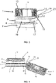
figure 1 est une vue en perspective arrière d'un dispositif de bouchage. - La
figure 2 est une vue en coupe d'un col de récipient destiné à recevoir le dispositif de bouchage de lafigure 1 . - La
figure 3 est une vue latérale du dispositif de bouchage monté sur le col du récipient et représentant le bouchon du dispositif de bouchage dans une position libérée dans laquelle il n'est plus en prise avec le col du récipient. - La
figure 4 est une vue latérale du dispositif de bouchage monté sur le col du récipient et représentant le bouchon du dispositif de bouchage dans une position basculée ouverte dans laquelle le bouchon est dégagé de l'orifice du col. - La
figure 5 est une vue en coupe du dispositif de bouchage monté sur le col du récipient et représentant le bouchon du dispositif de bouchage dans la position basculée ouverte de lafigure 4 . - La
figure 6 est une vue de dessus du dispositif de bouchage dans la position basculée ouverte desfigures 4 et 5 . - La
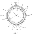
figure 7 est une vue de dessous du dispositif de bouchage.
- The
figure 1 is a rear perspective view of a capping device. - The
figure 2 is a cross-sectional view of a container neck intended to receive the closure device of thefigure 1 . - The
picture 3 - The
figure 4 is a side view of the closure device mounted on the neck of the container and showing the stopper of the closure device in a tilted open position in which the stopper is disengaged from the orifice of the neck. - The
figure 5 is a sectional view of the closure device mounted on the neck of the container and showing the stopper of the closure device in the tilted open position of thefigure 4 . - The
figure 6 is a top view of the closure device in the open tilted position of thefigure 4 and5 . - The
figure 7 is a bottom view of the closure device.
Dans la description et les figures, l'axe X correspond à l'axe de rotation du bouchon 1 du dispositif de bouchage lorsque celui-ci est vissé sur le col 2 du récipient. Par convention, l'orientation « radiale » est dirigée orthogonalement à l'axe X et l'orientation axiale est dirigée parallèlement à l'axe X. Les termes « externe » et « interne » sont utilisés pour définir la position relative d'un élément par rapport à un autre, par référence à l'axe X, un élément proche de l'axe X est ainsi qualifié d'interne par opposition à un élément externe situé radialement en périphérie.In the description and the figures, the axis X corresponds to the axis of rotation of the
Les termes « supérieur » et « inférieur » sont utilisés pour définir la position relative d'un élément par rapport à un autre par référence à une position dans laquelle l'orifice 3 du col 2 est dirigé vers le haut et le bouchon 1 est en position de fermeture sur le col 2 du récipient, un élément destiné à être placé plus bas étant désigné par inférieur et un élément destiné à être placé plus haut étant désigné par supérieur. Les termes « avant » et « arrière » sont utilisés pour définir la position relative d'un élément par rapport à un autre le long d'un diamètre perpendiculaire à l'axe X.The terms "upper" and "lower" are used to define the relative position of one element with respect to another with reference to a position in which the
En relation avec les
Comme représenté notamment sur la
Le dispositif de bouchage comporte une bague inférieure 9 qui est retenue sur le col 2 du récipient, un bouchon 1 qui est destiné à recouvrir l'orifice 3 du récipient de manière à l'obturer et un dispositif d'articulation 10 liant le bouchon 1 à la bague inférieure 9. Le bouchon 1 est mobile entre une position de fermeture, représentée sur la
Le bouchon 1 comporte une paroi supérieure 13 destinée à être disposée sensiblement orthogonalement à l'axe X, en regard de l'orifice 3 du col 2 lorsque ledit bouchon 1 est en position de fermeture. Le bouchon 1 comporte, en outre, une jupe périphérique externe 14 destinée à entourer le col 2 du récipient lorsque le bouchon 1 est en position de fermeture. La jupe périphérique externe 14 s'étend, vers le bas, perpendiculairement à la paroi supérieure 13, depuis la périphérie externe de ladite paroi supérieure 13. Le filetage hélicoïdal 7 est ménagé sur la face interne de la jupe périphérique externe 14.The
Comme représenté notamment sur la
De manière avantageuse, la bague inférieure 9 est, avant la première ouverture du récipient, reliée au bouchon 1 par des ponts frangibles, non illustrés, destinés à se rompre lors de l'ouverture du bouchon 1. Ces ponts frangibles constituent ainsi des témoins d'inviolabilité.Advantageously, the
La bague inférieure 9 est maintenue axialement sur le col 2 du récipient tout en pouvant tourner par rapport à celui-ci autour de l'axe X. Comme représenté sur les
La bague inférieure 9 est maintenue axialement sur le col 2 du récipient au moyen de la collerette d'accrochage 5. Comme représenté sur la
Comme représenté sur la
Le premier secteur 16 de la bague inférieure 9 comporte une zone avant 19 qui est diamétralement opposée au deuxième secteur 17 de la bague inférieure 9 et deux zones d'accrochage 20, 21 représentées sur les
De manière avantageuse, le deuxième secteur 17 s'étend sur une plage angulaire comprise entre 90 et 150°, la zone avant 19 du premier secteur 16 s'étend sur une plage angulaire comprise entre 60 et 150 tandis que chacune des deux zones d'accrochage 20, 21 s'étend sur une plage angulaire comprise entre 30 et 90°.Advantageously, the
Le dispositif d'articulation 10 comporte deux lamelles 11, 12, notamment visibles sur les
Les lamelles 11, 12 rejoignent la jupe périphérique externe 14 dans une portion échancrée. De même, les lamelles 11, 12 rejoignent le deuxième secteur 17 de la bague inférieure 2 dans une portion échancrée. En d'autres termes, les lamelles 11, 12 s'étendent sensiblement au-dessus de la limite inférieure de la jupe périphérique externe 9 et s'étendent sensiblement en dessous de la limite supérieure de la bague inférieure 3.The
Le dispositif de blocage comporte un taquet 23 qui fait saillie radialement vers l'extérieur depuis la jupe périphérique externe 14 du bouchon 1. Le taquet 23 s'étend circonférentiellement entre les deux lamelles 11, 12. Le dispositif de blocage comporte également une portion en saillie 24 qui fait saillie axialement vers le haut, c'est-à-dire vers la jupe périphérique externe 14 du bouchon 1, depuis une portion centrale 25 du deuxième secteur 17 de la bague inférieure 9. La portion en saillie 24 fait également saillie entre les deux lamelles 11, 12.The blocking device comprises a
Par ailleurs, le bouchon 1 comporte un talon 22, notamment visible sur la
Comme représenté sur les
Comme représenté sur les
Par ailleurs, la face interne et la face externe 27 de la portion en saillie 24 s'étendent parallèlement à l'axe X et sont alignées selon la direction axiale avec la face interne et la face externe 26 de la portion centrale 25 du deuxième secteur 17 de la bague inférieure 9. Ceci assure une continuité des faces interne et externe de la portion en saillie 24 avec celle de la bague inférieure 9, sans surface anguleuse.Furthermore, the internal face and the
Par ailleurs, en relation avec la
Par ailleurs, de manière avantageuse, comme représenté sur la
A titre d'exemple, l'épaisseur radiale ε1 de la portion en saillie est comprise entre 0.4 et 2 mm et de préférence comprise entre 1 et 2 mm.By way of example, the radial thickness ε1 of the projecting portion is between 0.4 and 2 mm and preferably between 1 and 2 mm.
De manière avantageuse, comme illustré par exemple sur la
Par ailleurs, comme représenté sur la
De manière avantageuse, lorsque le bouchon 1 est dans la position basculée ouverte, la portion en saillie 24 est prise en sandwich entre le taquet 23 et la collerette d'accrochage 5. En d'autres termes, lorsque le bouchon 1 est en position basculée ouverte, le taquet 23 et la portion en saillie 24 sont en contact l'un contre l'autre dans une zone située dans le plan de la collerette d'accrochage 5 et la portion en saillie 24 est également en contact contre la collerette d'accrochage 5. Ceci permet de garantir un blocage robuste du bouchon en position basculée ouverte.Advantageously, when the
La cinématique du bouchon 1 est la suivante. Lors du premier dévissage, le bouchon 1 quitte la position de fermeture et s'éloigne de la bague inférieure 9 jusqu'à la position libérée, illustrée sur la
Par la suite, le bouchon 1 peut alors être pivoté vers l'arrière en direction de la position basculée ouverte dans laquelle la jupe périphérique externe 14 s'étend vers le haut depuis la paroi supérieure 13. Lors du mouvement du bouchon 1 vers l'arrière en direction de sa position basculée ouverte, le taquet 23 vient en appui contre la portion en saillie 24 et entraîne ainsi le pivotement du deuxième secteur 17 de la bague inférieure 9 de la position relevée vers la position abaissée.Subsequently, the
Les possibilités d'étirement des lamelles 11, 10 conjointement aux caractéristiques précitées du dispositif de blocage, permettent de créer un point dur lors du basculement du bouchon 1 entre la position libérée, représentée sur la
Comme représenté sur les
Ainsi, le bouchon 1 demeure dans sa position basculée ouverte puisque, en raison de la disposition précitée, le bouchon 1 ne peut pas être pivoté vers la position libérée dans laquelle le bouchon 1 est en regard de l'orifice 3 de distribution tant que le deuxième secteur 17 de la bague inférieure 9 reste dans la position abaissée.
Pour refermer le bouchon 1, l'utilisateur bascule le bouchon 1 vers l'avant jusqu'à la position libérée. Lors de ce basculement, le contact entre le taquet 23 et la portion en saillie 24 disparait, ce qui autorise le mouvement du deuxième secteur 17 de la bague inférieure 9 vers la position relevée.Thus, the
To close
Lorsque le deuxième secteur 17 est dans la position relevée et que le bouchon 1 est dans la position libérée, ledit bouchon 1 peut alors être revissé sur le col 2 du récipient. Lors du revissage, la bague inférieure 9 est entraînée en rotation autour de l'axe X et le deuxième secteur 17 de la bague inférieure 9 pivote vers la position abaissée au fur et à mesure que le bouchon 1 s'approche de la collerette d'accrochage 5.When the
De manière avantageuse, l'ensemble du dispositif de bouchage est venu de moulage en une seule pièce de matière synthétique, tel que du polyéthylène et avantageusement du polyéthylène haute densité. De manière avantageuse, le dispositif de bouchage est moulé dans la configuration de la
Bien que l'invention ait été décrite en liaison avec plusieurs modes de réalisation particuliers, il est bien évident qu'elle n'y est nullement limitée et qu'elle comprend tous les équivalents techniques des moyens décrits ainsi que leurs combinaisons si celles-ci entrent dans le cadre de l'invention.Although the invention has been described in connection with several particular embodiments, it is obvious that it is in no way limited thereto and that it includes all the technical equivalents of the means described as well as their combinations if these fall within the scope of the invention.
L'usage du verbe « comporter », « comprendre » ou « inclure » et de ses formes conjuguées n'exclut pas la présence d'autres éléments ou d'autres étapes que ceux énoncés dans une revendication.The use of the verb "to comprise", "to understand" or "to include" and of its conjugated forms does not exclude the presence of other elements or other steps than those set out in a claim.
Dans les revendications, tout signe de référence entre parenthèses ne saurait être interprété comme une limitation de la revendication.In the claims, any reference sign in parentheses cannot be interpreted as a limitation of the claim.
Claims (10)
le dispositif de bouchage comportant en outre un dispositif de blocage configuré pour bloquer le bouchon (1) lorsqu'il est dans la position basculée ouverte, ledit dispositif de blocage comportant :
the plugging device further comprising a blocking device configured to block the plug (1) when it is in the open tilted position, said blocking device comprising:
Priority Applications (9)
| Application Number | Priority Date | Filing Date | Title |
|---|---|---|---|
| EP21382473.3A EP4095061B1 (en) | 2021-05-24 | 2021-05-24 | Closure device for a neck of a container |
| PT213824733T PT4095061T (en) | 2021-05-24 | 2021-05-24 | Closure device for a neck of a container |
| DK21382473.3T DK4095061T3 (en) | 2021-05-24 | 2021-05-24 | LOCK DEVICE FOR A NECK OF A CONTAINER |
| ES21382473T ES2960325T3 (en) | 2021-05-24 | 2021-05-24 | Closing device for the neck of a container |
| ARP220101371A AR125959A1 (en) | 2021-05-24 | 2022-05-23 | PLUG DEVICE DESIGNED TO BE ATTACHED TO THE NECK OF A CONTAINER |
| PCT/EP2022/064089 WO2022248491A1 (en) | 2021-05-24 | 2022-05-24 | Stoppering device intended to be fixed to the neck of a container |
| UY0001039787A UY39787A (en) | 2021-05-24 | 2022-05-24 | PLUGGING DEVICE INTENDED TO BE FIXED TO THE NECK OF A CONTAINER |
| BR112023024529A BR112023024529A2 (en) | 2021-05-24 | 2022-05-24 | CLOSING DEVICE INTENDED TO BE ATTACHED TO THE NECK OF A CONTAINER, AND ASSEMBLY |
| US17/752,269 US20230278765A1 (en) | 2021-05-24 | 2022-05-24 | Stopper Device Intended to be Attached to the Neck of a Container |
Applications Claiming Priority (1)
| Application Number | Priority Date | Filing Date | Title |
|---|---|---|---|
| EP21382473.3A EP4095061B1 (en) | 2021-05-24 | 2021-05-24 | Closure device for a neck of a container |
Publications (2)
| Publication Number | Publication Date |
|---|---|
| EP4095061A1 true EP4095061A1 (en) | 2022-11-30 |
| EP4095061B1 EP4095061B1 (en) | 2023-07-05 |
Family
ID=76197397
Family Applications (1)
| Application Number | Title | Priority Date | Filing Date |
|---|---|---|---|
| EP21382473.3A Active EP4095061B1 (en) | 2021-05-24 | 2021-05-24 | Closure device for a neck of a container |
Country Status (9)
| Country | Link |
|---|---|
| US (1) | US20230278765A1 (en) |
| EP (1) | EP4095061B1 (en) |
| AR (1) | AR125959A1 (en) |
| BR (1) | BR112023024529A2 (en) |
| DK (1) | DK4095061T3 (en) |
| ES (1) | ES2960325T3 (en) |
| PT (1) | PT4095061T (en) |
| UY (1) | UY39787A (en) |
| WO (1) | WO2022248491A1 (en) |
Citations (3)
| Publication number | Priority date | Publication date | Assignee | Title |
|---|---|---|---|---|
| WO2020193821A1 (en) | 2019-03-28 | 2020-10-01 | Betapack, S.A.U. | Capping device intended to be fixed on the neck of a container |
| WO2020227813A1 (en) * | 2019-05-13 | 2020-11-19 | Husky Injection Molding Systems Ltd. | Closure device for a container |
| EP3757033A1 (en) * | 2019-06-24 | 2020-12-30 | Taiwan Hon Chuan Enterprise Co., Ltd. | Bottle cap with non-break plates |
Family Cites Families (3)
| Publication number | Priority date | Publication date | Assignee | Title |
|---|---|---|---|---|
| FR2499519A1 (en) * | 1981-02-11 | 1982-08-13 | Grussen Jean | SCREW CAPSULE WITH INVIOLABILITY RING |
| FR2785264B1 (en) * | 1998-10-29 | 2001-01-05 | Crown Cork & Seal Tech Corp | CAPPING DEVICE |
| ES2944464T3 (en) * | 2019-07-12 | 2023-06-21 | Affaba & Ferrari S R L | Cap for container with easy opening and retention of the lid once opened |
-
2021
- 2021-05-24 ES ES21382473T patent/ES2960325T3/en active Active
- 2021-05-24 EP EP21382473.3A patent/EP4095061B1/en active Active
- 2021-05-24 PT PT213824733T patent/PT4095061T/en unknown
- 2021-05-24 DK DK21382473.3T patent/DK4095061T3/en active
-
2022
- 2022-05-23 AR ARP220101371A patent/AR125959A1/en unknown
- 2022-05-24 US US17/752,269 patent/US20230278765A1/en active Pending
- 2022-05-24 WO PCT/EP2022/064089 patent/WO2022248491A1/en unknown
- 2022-05-24 BR BR112023024529A patent/BR112023024529A2/en unknown
- 2022-05-24 UY UY0001039787A patent/UY39787A/en unknown
Patent Citations (3)
| Publication number | Priority date | Publication date | Assignee | Title |
|---|---|---|---|---|
| WO2020193821A1 (en) | 2019-03-28 | 2020-10-01 | Betapack, S.A.U. | Capping device intended to be fixed on the neck of a container |
| WO2020227813A1 (en) * | 2019-05-13 | 2020-11-19 | Husky Injection Molding Systems Ltd. | Closure device for a container |
| EP3757033A1 (en) * | 2019-06-24 | 2020-12-30 | Taiwan Hon Chuan Enterprise Co., Ltd. | Bottle cap with non-break plates |
Also Published As
| Publication number | Publication date |
|---|---|
| DK4095061T3 (en) | 2023-10-09 |
| ES2960325T3 (en) | 2024-03-04 |
| EP4095061B1 (en) | 2023-07-05 |
| AR125959A1 (en) | 2023-08-30 |
| UY39787A (en) | 2023-01-31 |
| WO2022248491A1 (en) | 2022-12-01 |
| PT4095061T (en) | 2023-10-04 |
| US20230278765A1 (en) | 2023-09-07 |
| BR112023024529A2 (en) | 2024-02-06 |
Similar Documents
| Publication | Publication Date | Title |
|---|---|---|
| FR3094353A1 (en) | CLOSING DEVICE INTENDED TO BE FIXED ON A NECK OF A CONTAINER | |
| EP1521710B1 (en) | Closure comprising a hinged cap moulded in closed position | |
| FR3070378A1 (en) | CAP WITH DOUBLE SEALING FOR CONTAINERS | |
| EP4003866A1 (en) | Lid with a secure opening | |
| WO2007006892A1 (en) | Closure with pouring means | |
| FR3106584A1 (en) | Capping device intended to be attached to the neck of a container | |
| FR3106582A1 (en) | CAPSULING DEVICE INTENDED TO BE FIXED ON THE MOUTH OF A CONTAINER AND ASSEMBLY INCLUDING A CONTAINER AND A CAPSULING DEVICE | |
| FR3108317A3 (en) | CAP FOR CONTAINER WITH THREADED NECK EQUIPPED WITH A LOCKING BODY BY ENGAGEMENT | |
| EP4095061B1 (en) | Closure device for a neck of a container | |
| EP4026783B1 (en) | Sealing device intended to be attached to the neck of a container | |
| EP1382539B1 (en) | Two-stage injection moulded closure | |
| FR3106583A1 (en) | Capping device intended to be attached to the neck of a container | |
| EP4005945B1 (en) | Assembly comprising a container and a closure device attached to the container | |
| FR2913677A1 (en) | DECAPSULATOR FOR BOTTLE CAPSULE OF A BOTTLE. | |
| EP3882173B1 (en) | Cap with hinge for a container comprising a neck | |
| EP4026782A1 (en) | Sealing device intended to be attached to the neck of a container | |
| EP4026785B1 (en) | Sealing device comprising a plug hinged to a base | |
| WO2003011699A1 (en) | Closure cap comprising an internal sealing skirt | |
| FR2917071A1 (en) | ENCLAQUETABLE PLUG WITH SEAL LIP | |
| EP3889063A1 (en) | Assembly for container with threaded neck and cap provided with axial positioning tabs and centring tabs | |
| EP0926075A1 (en) | Closure provided with a guarantee tab having three functions | |
| EP4147985A1 (en) | Device for storing a liquid comprising a container and a plug remaining securely attached to the container | |
| WO2024084148A1 (en) | Cap comprising a guide ramp for a boss | |
| FR2802182A1 (en) | Stopper for drinks bottle has pouring spout and hinged cap which fits over it, with first hinge attached to stopper and second hinge attached to cap which has two surfaces which abut when hinge is open | |
| EP4301669A1 (en) | Cap provided with a locking pin |
Legal Events
| Date | Code | Title | Description |
|---|---|---|---|
| PUAI | Public reference made under article 153(3) epc to a published international application that has entered the european phase |
Free format text: ORIGINAL CODE: 0009012 |
|
| STAA | Information on the status of an ep patent application or granted ep patent |
Free format text: STATUS: THE APPLICATION HAS BEEN PUBLISHED |
|
| AK | Designated contracting states |
Kind code of ref document: A1 Designated state(s): AL AT BE BG CH CY CZ DE DK EE ES FI FR GB GR HR HU IE IS IT LI LT LU LV MC MK MT NL NO PL PT RO RS SE SI SK SM TR |
|
| STAA | Information on the status of an ep patent application or granted ep patent |
Free format text: STATUS: REQUEST FOR EXAMINATION WAS MADE |
|
| 17P | Request for examination filed |
Effective date: 20230102 |
|
| RAV | Requested validation state of the european patent: fee paid |
Extension state: TN Effective date: 20230102 Extension state: MA Effective date: 20230102 |
|
| RBV | Designated contracting states (corrected) |
Designated state(s): AL AT BE BG CH CY CZ DE DK EE ES FI FR GB GR HR HU IE IS IT LI LT LU LV MC MK MT NL NO PL PT RO RS SE SI SK SM TR |
|
| GRAP | Despatch of communication of intention to grant a patent |
Free format text: ORIGINAL CODE: EPIDOSNIGR1 |
|
| STAA | Information on the status of an ep patent application or granted ep patent |
Free format text: STATUS: GRANT OF PATENT IS INTENDED |
|
| GRAS | Grant fee paid |
Free format text: ORIGINAL CODE: EPIDOSNIGR3 |
|
| INTG | Intention to grant announced |
Effective date: 20230509 |
|
| GRAA | (expected) grant |
Free format text: ORIGINAL CODE: 0009210 |
|
| STAA | Information on the status of an ep patent application or granted ep patent |
Free format text: STATUS: THE PATENT HAS BEEN GRANTED |
|
| AK | Designated contracting states |
Kind code of ref document: B1 Designated state(s): AL AT BE BG CH CY CZ DE DK EE ES FI FR GB GR HR HU IE IS IT LI LT LU LV MC MK MT NL NO PL PT RO RS SE SI SK SM TR |
|
| P01 | Opt-out of the competence of the unified patent court (upc) registered |
Effective date: 20230602 |
|
| REG | Reference to a national code |
Ref country code: CH Ref legal event code: EP |
|
| REG | Reference to a national code |
Ref country code: AT Ref legal event code: REF Ref document number: 1584659 Country of ref document: AT Kind code of ref document: T Effective date: 20230715 |
|
| REG | Reference to a national code |
Ref country code: DE Ref legal event code: R096 Ref document number: 602021003292 Country of ref document: DE |
|
| REG | Reference to a national code |
Ref country code: IE Ref legal event code: FG4D Free format text: LANGUAGE OF EP DOCUMENT: FRENCH |
|
| REG | Reference to a national code |
Ref country code: PT Ref legal event code: SC4A Ref document number: 4095061 Country of ref document: PT Date of ref document: 20231004 Kind code of ref document: T Free format text: AVAILABILITY OF NATIONAL TRANSLATION Effective date: 20230928 |
|
| REG | Reference to a national code |
Ref country code: DK Ref legal event code: T3 Effective date: 20231002 |
|
| REG | Reference to a national code |
Ref country code: NL Ref legal event code: FP |
|
| REG | Reference to a national code |
Ref country code: LT Ref legal event code: MG9D |
|
| REG | Reference to a national code |
Ref country code: NO Ref legal event code: T2 Effective date: 20230705 |
|
| PG25 | Lapsed in a contracting state [announced via postgrant information from national office to epo] |
Ref country code: GR Free format text: LAPSE BECAUSE OF FAILURE TO SUBMIT A TRANSLATION OF THE DESCRIPTION OR TO PAY THE FEE WITHIN THE PRESCRIBED TIME-LIMIT Effective date: 20231006 |
|
| PG25 | Lapsed in a contracting state [announced via postgrant information from national office to epo] |
Ref country code: IS Free format text: LAPSE BECAUSE OF FAILURE TO SUBMIT A TRANSLATION OF THE DESCRIPTION OR TO PAY THE FEE WITHIN THE PRESCRIBED TIME-LIMIT Effective date: 20231105 |
|
| PG25 | Lapsed in a contracting state [announced via postgrant information from national office to epo] |
Ref country code: SE Free format text: LAPSE BECAUSE OF FAILURE TO SUBMIT A TRANSLATION OF THE DESCRIPTION OR TO PAY THE FEE WITHIN THE PRESCRIBED TIME-LIMIT Effective date: 20230705 Ref country code: RS Free format text: LAPSE BECAUSE OF FAILURE TO SUBMIT A TRANSLATION OF THE DESCRIPTION OR TO PAY THE FEE WITHIN THE PRESCRIBED TIME-LIMIT Effective date: 20230705 Ref country code: LV Free format text: LAPSE BECAUSE OF FAILURE TO SUBMIT A TRANSLATION OF THE DESCRIPTION OR TO PAY THE FEE WITHIN THE PRESCRIBED TIME-LIMIT Effective date: 20230705 Ref country code: LT Free format text: LAPSE BECAUSE OF FAILURE TO SUBMIT A TRANSLATION OF THE DESCRIPTION OR TO PAY THE FEE WITHIN THE PRESCRIBED TIME-LIMIT Effective date: 20230705 Ref country code: IS Free format text: LAPSE BECAUSE OF FAILURE TO SUBMIT A TRANSLATION OF THE DESCRIPTION OR TO PAY THE FEE WITHIN THE PRESCRIBED TIME-LIMIT Effective date: 20231105 Ref country code: HR Free format text: LAPSE BECAUSE OF FAILURE TO SUBMIT A TRANSLATION OF THE DESCRIPTION OR TO PAY THE FEE WITHIN THE PRESCRIBED TIME-LIMIT Effective date: 20230705 Ref country code: GR Free format text: LAPSE BECAUSE OF FAILURE TO SUBMIT A TRANSLATION OF THE DESCRIPTION OR TO PAY THE FEE WITHIN THE PRESCRIBED TIME-LIMIT Effective date: 20231006 Ref country code: FI Free format text: LAPSE BECAUSE OF FAILURE TO SUBMIT A TRANSLATION OF THE DESCRIPTION OR TO PAY THE FEE WITHIN THE PRESCRIBED TIME-LIMIT Effective date: 20230705 |
|
| REG | Reference to a national code |
Ref country code: AT Ref legal event code: UEP Ref document number: 1584659 Country of ref document: AT Kind code of ref document: T Effective date: 20230705 |
|
| PG25 | Lapsed in a contracting state [announced via postgrant information from national office to epo] |
Ref country code: PL Free format text: LAPSE BECAUSE OF FAILURE TO SUBMIT A TRANSLATION OF THE DESCRIPTION OR TO PAY THE FEE WITHIN THE PRESCRIBED TIME-LIMIT Effective date: 20230705 |
|
| REG | Reference to a national code |
Ref country code: ES Ref legal event code: FG2A Ref document number: 2960325 Country of ref document: ES Kind code of ref document: T3 Effective date: 20240304 |
|
| PG25 | Lapsed in a contracting state [announced via postgrant information from national office to epo] |
Ref country code: SM Free format text: LAPSE BECAUSE OF FAILURE TO SUBMIT A TRANSLATION OF THE DESCRIPTION OR TO PAY THE FEE WITHIN THE PRESCRIBED TIME-LIMIT Effective date: 20230705 Ref country code: RO Free format text: LAPSE BECAUSE OF FAILURE TO SUBMIT A TRANSLATION OF THE DESCRIPTION OR TO PAY THE FEE WITHIN THE PRESCRIBED TIME-LIMIT Effective date: 20230705 Ref country code: EE Free format text: LAPSE BECAUSE OF FAILURE TO SUBMIT A TRANSLATION OF THE DESCRIPTION OR TO PAY THE FEE WITHIN THE PRESCRIBED TIME-LIMIT Effective date: 20230705 Ref country code: CZ Free format text: LAPSE BECAUSE OF FAILURE TO SUBMIT A TRANSLATION OF THE DESCRIPTION OR TO PAY THE FEE WITHIN THE PRESCRIBED TIME-LIMIT Effective date: 20230705 Ref country code: SK Free format text: LAPSE BECAUSE OF FAILURE TO SUBMIT A TRANSLATION OF THE DESCRIPTION OR TO PAY THE FEE WITHIN THE PRESCRIBED TIME-LIMIT Effective date: 20230705 |