EP4095056A1 - Containers and methods for improved mechanical strength - Google Patents
Containers and methods for improved mechanical strength Download PDFInfo
- Publication number
- EP4095056A1 EP4095056A1 EP22185366.6A EP22185366A EP4095056A1 EP 4095056 A1 EP4095056 A1 EP 4095056A1 EP 22185366 A EP22185366 A EP 22185366A EP 4095056 A1 EP4095056 A1 EP 4095056A1
- Authority
- EP
- European Patent Office
- Prior art keywords
- protective coating
- container
- containers
- dlc
- bottles
- Prior art date
- Legal status (The legal status is an assumption and is not a legal conclusion. Google has not performed a legal analysis and makes no representation as to the accuracy of the status listed.)
- Granted
Links
Images


Classifications
-
- B—PERFORMING OPERATIONS; TRANSPORTING
- B65—CONVEYING; PACKING; STORING; HANDLING THIN OR FILAMENTARY MATERIAL
- B65D—CONTAINERS FOR STORAGE OR TRANSPORT OF ARTICLES OR MATERIALS, e.g. BAGS, BARRELS, BOTTLES, BOXES, CANS, CARTONS, CRATES, DRUMS, JARS, TANKS, HOPPERS, FORWARDING CONTAINERS; ACCESSORIES, CLOSURES, OR FITTINGS THEREFOR; PACKAGING ELEMENTS; PACKAGES
- B65D1/00—Rigid or semi-rigid containers having bodies formed in one piece, e.g. by casting metallic material, by moulding plastics, by blowing vitreous material, by throwing ceramic material, by moulding pulped fibrous material or by deep-drawing operations performed on sheet material
- B65D1/02—Bottles or similar containers with necks or like restricted apertures, designed for pouring contents
-
- B—PERFORMING OPERATIONS; TRANSPORTING
- B65—CONVEYING; PACKING; STORING; HANDLING THIN OR FILAMENTARY MATERIAL
- B65D—CONTAINERS FOR STORAGE OR TRANSPORT OF ARTICLES OR MATERIALS, e.g. BAGS, BARRELS, BOTTLES, BOXES, CANS, CARTONS, CRATES, DRUMS, JARS, TANKS, HOPPERS, FORWARDING CONTAINERS; ACCESSORIES, CLOSURES, OR FITTINGS THEREFOR; PACKAGING ELEMENTS; PACKAGES
- B65D1/00—Rigid or semi-rigid containers having bodies formed in one piece, e.g. by casting metallic material, by moulding plastics, by blowing vitreous material, by throwing ceramic material, by moulding pulped fibrous material or by deep-drawing operations performed on sheet material
- B65D1/02—Bottles or similar containers with necks or like restricted apertures, designed for pouring contents
- B65D1/0207—Bottles or similar containers with necks or like restricted apertures, designed for pouring contents characterised by material, e.g. composition, physical features
- B65D1/0215—Bottles or similar containers with necks or like restricted apertures, designed for pouring contents characterised by material, e.g. composition, physical features multilayered
-
- B—PERFORMING OPERATIONS; TRANSPORTING
- B65—CONVEYING; PACKING; STORING; HANDLING THIN OR FILAMENTARY MATERIAL
- B65D—CONTAINERS FOR STORAGE OR TRANSPORT OF ARTICLES OR MATERIALS, e.g. BAGS, BARRELS, BOTTLES, BOXES, CANS, CARTONS, CRATES, DRUMS, JARS, TANKS, HOPPERS, FORWARDING CONTAINERS; ACCESSORIES, CLOSURES, OR FITTINGS THEREFOR; PACKAGING ELEMENTS; PACKAGES
- B65D23/00—Details of bottles or jars not otherwise provided for
- B65D23/08—Coverings or external coatings
- B65D23/0807—Coatings
- B65D23/0814—Coatings characterised by the composition of the material
-
- C—CHEMISTRY; METALLURGY
- C03—GLASS; MINERAL OR SLAG WOOL
- C03C—CHEMICAL COMPOSITION OF GLASSES, GLAZES OR VITREOUS ENAMELS; SURFACE TREATMENT OF GLASS; SURFACE TREATMENT OF FIBRES OR FILAMENTS MADE FROM GLASS, MINERALS OR SLAGS; JOINING GLASS TO GLASS OR OTHER MATERIALS
- C03C17/00—Surface treatment of glass, not in the form of fibres or filaments, by coating
- C03C17/001—General methods for coating; Devices therefor
- C03C17/003—General methods for coating; Devices therefor for hollow ware, e.g. containers
- C03C17/005—Coating the outside
-
- C—CHEMISTRY; METALLURGY
- C03—GLASS; MINERAL OR SLAG WOOL
- C03C—CHEMICAL COMPOSITION OF GLASSES, GLAZES OR VITREOUS ENAMELS; SURFACE TREATMENT OF GLASS; SURFACE TREATMENT OF FIBRES OR FILAMENTS MADE FROM GLASS, MINERALS OR SLAGS; JOINING GLASS TO GLASS OR OTHER MATERIALS
- C03C17/00—Surface treatment of glass, not in the form of fibres or filaments, by coating
- C03C17/22—Surface treatment of glass, not in the form of fibres or filaments, by coating with other inorganic material
-
- C—CHEMISTRY; METALLURGY
- C23—COATING METALLIC MATERIAL; COATING MATERIAL WITH METALLIC MATERIAL; CHEMICAL SURFACE TREATMENT; DIFFUSION TREATMENT OF METALLIC MATERIAL; COATING BY VACUUM EVAPORATION, BY SPUTTERING, BY ION IMPLANTATION OR BY CHEMICAL VAPOUR DEPOSITION, IN GENERAL; INHIBITING CORROSION OF METALLIC MATERIAL OR INCRUSTATION IN GENERAL
- C23C—COATING METALLIC MATERIAL; COATING MATERIAL WITH METALLIC MATERIAL; SURFACE TREATMENT OF METALLIC MATERIAL BY DIFFUSION INTO THE SURFACE, BY CHEMICAL CONVERSION OR SUBSTITUTION; COATING BY VACUUM EVAPORATION, BY SPUTTERING, BY ION IMPLANTATION OR BY CHEMICAL VAPOUR DEPOSITION, IN GENERAL
- C23C14/00—Coating by vacuum evaporation, by sputtering or by ion implantation of the coating forming material
- C23C14/06—Coating by vacuum evaporation, by sputtering or by ion implantation of the coating forming material characterised by the coating material
- C23C14/0605—Carbon
-
- C—CHEMISTRY; METALLURGY
- C23—COATING METALLIC MATERIAL; COATING MATERIAL WITH METALLIC MATERIAL; CHEMICAL SURFACE TREATMENT; DIFFUSION TREATMENT OF METALLIC MATERIAL; COATING BY VACUUM EVAPORATION, BY SPUTTERING, BY ION IMPLANTATION OR BY CHEMICAL VAPOUR DEPOSITION, IN GENERAL; INHIBITING CORROSION OF METALLIC MATERIAL OR INCRUSTATION IN GENERAL
- C23C—COATING METALLIC MATERIAL; COATING MATERIAL WITH METALLIC MATERIAL; SURFACE TREATMENT OF METALLIC MATERIAL BY DIFFUSION INTO THE SURFACE, BY CHEMICAL CONVERSION OR SUBSTITUTION; COATING BY VACUUM EVAPORATION, BY SPUTTERING, BY ION IMPLANTATION OR BY CHEMICAL VAPOUR DEPOSITION, IN GENERAL
- C23C14/00—Coating by vacuum evaporation, by sputtering or by ion implantation of the coating forming material
- C23C14/22—Coating by vacuum evaporation, by sputtering or by ion implantation of the coating forming material characterised by the process of coating
- C23C14/221—Ion beam deposition
-
- C—CHEMISTRY; METALLURGY
- C03—GLASS; MINERAL OR SLAG WOOL
- C03C—CHEMICAL COMPOSITION OF GLASSES, GLAZES OR VITREOUS ENAMELS; SURFACE TREATMENT OF GLASS; SURFACE TREATMENT OF FIBRES OR FILAMENTS MADE FROM GLASS, MINERALS OR SLAGS; JOINING GLASS TO GLASS OR OTHER MATERIALS
- C03C2217/00—Coatings on glass
- C03C2217/20—Materials for coating a single layer on glass
- C03C2217/28—Other inorganic materials
-
- C—CHEMISTRY; METALLURGY
- C03—GLASS; MINERAL OR SLAG WOOL
- C03C—CHEMICAL COMPOSITION OF GLASSES, GLAZES OR VITREOUS ENAMELS; SURFACE TREATMENT OF GLASS; SURFACE TREATMENT OF FIBRES OR FILAMENTS MADE FROM GLASS, MINERALS OR SLAGS; JOINING GLASS TO GLASS OR OTHER MATERIALS
- C03C2217/00—Coatings on glass
- C03C2217/70—Properties of coatings
- C03C2217/78—Coatings specially designed to be durable, e.g. scratch-resistant
-
- C—CHEMISTRY; METALLURGY
- C03—GLASS; MINERAL OR SLAG WOOL
- C03C—CHEMICAL COMPOSITION OF GLASSES, GLAZES OR VITREOUS ENAMELS; SURFACE TREATMENT OF GLASS; SURFACE TREATMENT OF FIBRES OR FILAMENTS MADE FROM GLASS, MINERALS OR SLAGS; JOINING GLASS TO GLASS OR OTHER MATERIALS
- C03C2218/00—Methods for coating glass
- C03C2218/10—Deposition methods
- C03C2218/15—Deposition methods from the vapour phase
Definitions
- a DLC coating imparts greater initial lubricity and maintains suitable lubricity for a longer period of time as compared to conventional containers. This effect is also beneficial because minimal friction among beverage bottles is desirable during processing, particularly during refilling operation.
- the disclosed containers and methods provide the ability to increase the mechanical strength of containers, without having undesirable effects on the overall initial optical clarity of the container material, and further to enhance the lubricity of the container surface, which in turn decreases the containers' susceptibility to scuffing.
- the container is a glass container, whereas in other instances, the container is a polyester container, such as a polyethylene terephthalate (PET) container.
- the container comprises a body structure that comprises glass and polyethylene terephthalate (PET).
- One DLC-Coated Bottle and three New Bottles each underwent an internal caustic wash test and analysis, in which each bottle was washed with a 2.25 wt% NaOH aqueous solution at 75°C for 3 hours, which is equivalent to about 36 washing cycles. After this caustic wash test, a tilt angle test was performed on each test sample.
Landscapes
- Chemical & Material Sciences (AREA)
- Engineering & Computer Science (AREA)
- Mechanical Engineering (AREA)
- Chemical Kinetics & Catalysis (AREA)
- Materials Engineering (AREA)
- Organic Chemistry (AREA)
- Metallurgy (AREA)
- General Chemical & Material Sciences (AREA)
- Life Sciences & Earth Sciences (AREA)
- Geochemistry & Mineralogy (AREA)
- Ceramic Engineering (AREA)
- Details Of Rigid Or Semi-Rigid Containers (AREA)
- Surface Treatment Of Glass (AREA)
- Physical Vapour Deposition (AREA)
- Chemical Vapour Deposition (AREA)
- Containers Having Bodies Formed In One Piece (AREA)
- Packages (AREA)
Abstract
Description
- This application claims the benefit of priority to
U.S. Provisional Patent Application No. 62/332,057, filed May 5, 2016 - This disclosure relates to containers having improved mechanical strength, and methods for improving mechanical strength.
- For beverage containers, one of the primary selling points is optical clarity. Historically, glass has been used as the preferred material for beverage containers because of its optical clarity and excellent chemical durability relative to other materials. It is commonly known that glass containers may be cleaned, refilled, and resold after their initial use. Refillable containers reduce waste and often are more cost-effective for manufacturers.
- Soda lime glass is commonly used for glass beverage containers. However, even though the inherent chemical stability of its silica backbone enables glass to withstand most types of environmental exposure indefinitely without bulk failure, long term exposure to a variety of natural elements induces the gradual degradation of its clear appearance (optical clarity). For example, roughening of the glass surface can occur through prolonged contact with static water through ion exchange reactions that result in the leach of Na2O from the surface.
- Moreover, the practical strength of most glass containers is consistently less than theoretical glass strength, which most likely arises because of the brittle nature of glass. As a result, any surface flaws, such as surface scratches, create concentrated stress sites which can propagate into major failures in the glass under certain conditions. These surface flaws can be created by at least the following: (1) the manufacturing process, (2) mechanical force, and (3) chemical attacks (condensation and caustic wash). Consequently, aggressive caustic washes of reusable glass containers with alkali solutions, combined with mechanical abrasions along filling lines (and refilling lines) and during transportation, lead to readily visible cosmetic defects such as surface scuffing and scratching. These defects, in turn, make such containers aesthetically undesirable and ultimately render them unusable.
- As an alternative to glass containers, polyesters and particularly polyethylene terephthalate (PET) containers have been used for packaging beverages such as carbonated soft drinks (CSD) for many years. Refillable PET bottles represent a growing aspect of renewable and sustainable packaging applications. Refillable PET bottles often can be reused for 20 or more refilling cycles before neck and base cracking necessitates removing the bottle from circulation and routing it to a recycling processor. Neck and base cracking generally derives from caustic stress cracking that etches and damages the bottle, resulting from the high temperature caustic (aqueous base) washing process used for sterilization.
- Therefore, there is a continuing need for improved containers, particularly improved reusable beverage containers. The containers will desirably have greater mechanical strength, thereby minimizing the containers' susceptibility to surface flaws during processing for reuse. Consequently, containers with greater mechanical strength would likely increase bottle cycle times (packaging life cycle) and decrease adverse environmental impacts associated with beverage packaging. New methods for increasing mechanical strength of containers are also desirable.
- This disclosure provides new containers having improved mechanical strength and further provides methods for improving mechanical strength of containers.
- According to one aspect, for example, this disclosure provides a glass container comprising:
- a body structure having a top end that defines an opening, a sealed base end, and a sidewall structure extending between the top and base ends, wherein the sidewall structure has an interior surface and an exterior surface, the interior surface defining an interior space; and
- a protective coating on at least a portion of the exterior surface of the sidewall structure, the protective coating comprising diamond-like carbon,
- wherein the glass container is substantially clear.
- In a further aspect, for example, this disclosure provides a method for enhancing the mechanical strength of a glass container, the method comprising:
- providing a body structure having a top end that defines an opening, a sealed base end, and a sidewall structure extending between the top and base ends, wherein the sidewall structure has an interior surface and an exterior surface, the interior surface defining an interior space; and
- depositing a protective coating on at least a portion of the exterior surface of the sidewall structure, the protective coating comprising diamond-like carbon,
- wherein the glass container is substantially clear.
- In yet a further aspect, for example, this disclosure provides a polyethylene terephthalate (PET) container comprising:
- a body structure having a top end that defines an opening, a sealed base end, and a sidewall structure extending between the top and base ends, wherein the sidewall structure has an interior surface and an exterior surface, the interior surface defining an interior space; and
- a protective coating on at least a portion of the exterior surface of the sidewall structure, the protective coating comprising diamond-like carbon.
- In yet a further aspect, for example, this disclosure provides a method for enhancing the mechanical strength of a polyethylene terephthalate (PET) container, the method comprising:
- providing a body structure having a top end that defines an opening, a sealed base end, and a sidewall structure extending between the top and base ends, wherein the sidewall structure has an interior surface and an exterior surface, the interior surface defining an interior space; and
- depositing a protective coating on at least a portion of the exterior surface of the sidewall structure, the protective coating comprising diamond-like carbon.
- These and various other aspects and embodiments of this disclosure are illustrated in the drawings, examples, data, and detailed description that follow.
-
-
FIG. 1A is a side elevation view of one embodiment of a container in accordance with the present disclosure. -
FIG. 1B is a cross-sectional view of the container inFIG. 1A taken at line B-B. -
FIG. 2 is a cross-sectional view of another embodiment of a container in accordance with the present disclosure. -
FIG. 3 is a cross-sectional view of still another embodiment of a container in accordance with the present disclosure. -
FIG. 4 graphically illustrates the test results from the comparative coefficient friction analysis in Example 1. -
FIG. 5 graphically illustrates the test results from the comparative coefficient friction analysis in Example 2. -
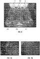
FIG. 6 provides photographs of various glass containers that were analyzed for scuffing in Example 3. In order (from left to right) are:- New Bottle A (no DLC coating);
- DLC-Coated Bottle (20 nm thick DLC coating); and
- New Bottle B (no DLC coating).
-
FIG. 7A is an optical microscope image (enlarged about 100×) of a portion of the exterior surface of the New Bottle A inFIG. 6 . -
FIG. 7B is an optical microscope image (enlarged about 100×) of a portion of the exterior surface of DLC-Coated Bottle inFIG. 6 . - Containers and associated methods disclosed herein include the combination of a body structure and a protective coating of diamond-like carbon (DLC) disposed thereon. The disclosed DLC coating surprisingly maintains the structural, and consequently the aesthetic, properties of the resulting containers for a greater period of time as compared to conventional containers without the protective coating. As a result, the present containers are capable of sustaining an increased number of bottle wash and refill cycles as compared to conventional containers.
- Furthermore, it has now been unexpectedly discovered that employing a DLC coating as a protective coating on at least a portion of a glass container preserves the optical clarity of the glass containers by reducing, minimizing, or at the very least delaying the formation of surface flaws created by the reprocessing of the glass containers for purposes of reuse. This result is beneficial because sustaining optical clarity increases the reusability and life cycle of the glass containers, which in turn reduces manufacturing costs and waste. It has also been unexpectedly discovered that depositing the DLC coating via a high-energy process also provides a substantially clear coating, and consequently, a substantially colorless glass container.
- Still further, it has also been unexpectedly discovered that a DLC coating imparts greater initial lubricity and maintains suitable lubricity for a longer period of time as compared to conventional containers. This effect is also beneficial because minimal friction among beverage bottles is desirable during processing, particularly during refilling operation. The disclosed containers and methods provide the ability to increase the mechanical strength of containers, without having undesirable effects on the overall initial optical clarity of the container material, and further to enhance the lubricity of the container surface, which in turn decreases the containers' susceptibility to scuffing.
- Aspects of this disclosure provide for new containers and methods that enhance the mechanical strength of containers. This disclosure further provides for containers that include a DLC coating that increases the number of container wash and refill cycles while also decreasing certain adverse effects on the aesthetic properties of the containers.
- In one aspect, the disclosure provides for a container comprising a body structure and a protective coating disposed on at least a portion of the body structure, in which the protective coating comprises diamond-like carbon (DLC).
- Diamond-like carbon (DLC) is a metastable amorphous carbon material, but in some instances may include a microcrystalline phase. In some aspects, DLC films or coatings may be generally characterized as having high corrosion resistance, high wear resistance, and low friction coefficients in both dry and wet conditions. However, it was unexpectedly discovered that additional particularly desirable characteristics resulted when DLC coatings were applied to beverage bottles or containers, including certain benefits generally associated with both organic and inorganic materials. As a result, DLC coatings beneficially provided the ability to employ a long-lasting, effective protective coating for containers, particularly beverage containers.
- Additionally, DLC films or coatings can be neutral transparent (i.e., having minimal to no visible light absorption or color hue), which provides further advantages for beverage container use. When combined with DLC's long-lasting, effective protective coating properties and due to the inert nature of DLC, DLC-coated bottles have the further advantage of being easily cleaned/sterilized, which again is particularly desirable for reusable beverage containers.
- In some instances, the DLC protective coating has a thickness from about 0.01 µm to about 10 µm; alternatively from about 0.01 µm to about 0.02 µm; or alternatively from about 1 µm to 10 µm. According to another aspect, the protective coating can have a thickness of about 0.01 µm, 0.02 µm, 0.05 µm, 0.1 µm, 0.15 µm, 0.20 µm, 0.25 µm, 0.3 µm, 0.35 µm, 0.4 µm, 0.45 µm, 0.5 µm, 0.55 µm, 0.6 µm, 0.65 µm, 0.7 µm, 0.75 µm, 0.8 µm, 0.85 µm, 0.9 µm, 0.95 µm, 1 µm, 1.5 µm, 2 µm, 2.5 µm, 3 µm, 3.5 µm, 4 µm, 4.5 µm, 5 µm, 5.5 µm, 6 µm, 6.5 µm, 7 µm, 7.5 µm, 8 µm, 8.5 µm, 9 µm, 9.5 µm, or 10 µm. The protective coating also can have a thickness range between any of these recited thicknesses.
- In certain aspects, the DLC-coated containers according to this disclosure can exhibit substantially lower coefficients of friction as compared to uncoated containers or containers that are coated with conventional coatings such as SnO2. For example, the DLC-coated bottles according to this disclosure can have a coefficient of friction that is up to or about 0.25; alternatively, of about 0.01 to about 0.25; or alternatively, of 0.05 to about 0.2. According to another aspect, the present DLC-coated containers can have a coefficient of friction of about 0.001, 0.005, 0.01, 0.02, 0.03, 0.04, 0.05, 0.06, 0.07, 0.08, 0.09, 0.1, 0.11, 0.12, 0.13, 0.14, 0.15, 0.16, 0.17, 0.18, 0.19, 0.2, 0.21, 0.22, 0.23, 0.24, or 0.25. The DLC-coated containers of this disclosure can also can have a coefficient of friction range between any of these recited coefficients of friction.
- In further aspects, the present DLC-coated containers can have, after about 30 caustic washes, a coefficient of friction that is up to or about 0.25. Alternatively, after about 30 caustic washes, the present DLC-coated containers may have a coefficient of friction of about 0.24 or less, 0.23 or less, 0.22 or less, 0.21 or less, 0.2 or less, 0.19 or less, 0.18 or less, 0.17 or less, 0.16 or less, 0.15 or less, 0.14 or less, 0.13 or less, 0.12 or less, 0.11 or less, 0.1 or less, 0.09 or less, 0.08 or less, 0.07 or less, 0.06 or less, 0.05 or less, 0.04 or less, 0.03, 0.02 or less, 0.01 or less, or 0.005 or less. These DLC-coated containers also can have a coefficient of friction range between any of these recited coefficients of friction.
- As used herein, a "caustic wash" is generally defined as a high temperature aqueous base washing process, which is typically used for sterilization of containers for reuse. During each refilling cycle of a reusable container, the container undergoes a caustic wash. In one instance, a caustic wash includes immersing and/or flushing the interior/exterior surfaces of used containers with 2.25% NaOH water solution at 75°C for about 5 to 7 minutes, and then rinsing the containers with clean water. The caustic washing used in each refilling cycle commonly etches and damages conventional containers (i.e., containers without the DLC protective coating). Reusable beverage containers often can be reused for up to about 20 refilling cycles for PET containers or 30 refilling cycles for glass containers, before structural and/or aesthetic degradation necessitates removing the container from circulation. Surprisingly, it has been discovered that by employing a DLC protective coating on the exterior surface of the present containers, the mechanical strength of the containers is substantially increased, thereby being more resistant to high temperature caustic washing, and consequently, increasing the container life cycle.
- One embodiment of a container is shown in
FIGS. 1A and 1B . Thecontainer 100 includes atop end 102 that defines anopening 104, a sealedbase end 106, and asidewall structure 108 extending between the top and base ends 102, 106. Thesidewall structure 108 has aninterior surface 110 and anexterior surface 112, in which theinterior surface 110 defines an interior space 114. Thecontainer 100 further includes aprotective coating 116 on at least a portion of theexterior surface 112 of thesidewall structure 108. - In certain instances, the protective coating may also be disposed on at least a portion of the top end of the
container 102, on at least a portion of the base end of the container106, or both. Examples of such containers, which are shown in the cross-section, are illustrated inFIGS. 2 and 3 . - In
FIG. 2 , thecontainer 200 includes aprotective coating 216 disposed on at least a portion of theexterior surface 212 of thesidewall structure 208 and the sealed base end 206. InFIG. 3 , thecontainer 300 includes aprotective coating 316 disposed on at least a portion of theexterior surface 312 of thesidewall structure 308 and thetop end 302. - In some instances, the container is a glass container, whereas in other instances, the container is a polyester container, such as a polyethylene terephthalate (PET) container. In one aspect, the container comprises a body structure that comprises glass and polyethylene terephthalate (PET).
- In certain aspects, the protective coating is applied onto at least a portion of the body structure using a high energy deposition process. In one aspect, the high energy deposition process can be ion beam deposition. Hydrocarbon gases, such as CH4, C2H6, C2H4, and C2H2, may be used as precursors in this type of deposition process. These precursor gases may also be diluted with, for example, H2 and/or Ar, during the deposition process.
- As used herein, "high-energy" is defined as energy in the amount of about 25eV or greater. In an aspect, the amount of energy is from about 50eV to about 500 eV. In other instances, the amount of energy is about 50 eV, 55 eV, 60 eV, 65 eV, 70 eV, 75 eV, 80 eV, 85 eV, 90 eV, 95 eV, 100 eV, 105 eV, 110 eV, 115, eV, 120 eV, 125 eV, 130 eV, 135 eV, 140 eV, 145 eV, 150 eV, 155 eV, 160 eV, 165 eV, 170 eV, 175 eV, 180 eV, 185 eV, 190 eV, 195 eV, 200 eV, 205 eV, 210 eV, 215, eV, 220 eV, 225 eV, 230 eV, 235 eV, 240 eV, 245 eV, 250 eV, 255 eV, 260 eV, 265 eV, 270 eV, 275 eV, 280 eV, 285 eV, 290 eV, 295 eV, 300 eV, 305 eV, 310 eV, 315, eV, 320 eV, 325 eV, 330 eV, 335 eV, 340 eV, 345 eV, 350 eV, 355 eV, 360 eV, 365 eV, 370 eV, 375 eV, 380 eV, 385 eV, 390 eV, 395 eV, 400 eV, 405 eV, 410 eV, 415, eV, 420 eV, 425 eV, 430 eV, 435 eV, 440 eV, 445 eV, 450 eV, 455 eV, 460 eV, 465 eV, 470 eV, 475 eV, 480 eV, 485 eV, 490 eV, 495 eV, or 500 eV. The energy also may be in an amount that is in a range between any of the recited energy values.
- In some aspects, the protective coating is directly deposited onto at least a portion of the body structure of the container. In such embodiments, no other coating is disposed between the protective coating and the body structure.
- In other aspects, the protective coating is indirectly deposited onto at least a portion of the body structure of the container. In such instances, one or more other coatings are deposited or otherwise disposed between the protective coating and the body structure. In one instance, one or more other coatings, such as a SnO2 hot end coating or a stearate cold end coating, may be disposed onto the body structure prior to depositing the protective coating, such that the one or more other coatings are located between the body structure and protective coating of the resulting container.
- In certain aspects, the present containers may be substantially clear. For example, in one instance, a glass container having the protective coating may be substantially clear.
- As used herein, "substantially clear" when used to describe a glass bottle is defined as a glass bottle having a purity of up to 6% and a brightness of 65 % or greater. The purity and brightness are each measured at a dominant wavelength between 500-573 nm, calibrated at a 38 mm glass thickness equivalent.
- The purity (the excitation purity) of a stimulus is the difference from the illuminant's white point to the furthest point on the chromaticity diagram with the same hue (dominant wavelength for monochromatic sources). As used herein, "purity", according to the CIE 1931 color space, is defined by the following formula:

- X, Y is the chromaticity of the stimulus;
- Xn, Yn is the chromaticity of the white point; and
- XI, YI is the point on the perimeter whose line segment to the white point contains the chromaticity of the stimulus.
- Also as used herein, "brightness" is the light transmission equivalent through 38 mm glass thickness.
- In some aspects, the protective coating may also include one or more dopants. Non-limiting examples of suitable dopants include hydrogen, oxygen, nitrogen, fluorine, boron, silicon, metals, and combinations thereof.
- Without being bound to a single theory, by employing one or more dopants within the protective coating, it is thought that any remaining optically-absorbing sp2 bonds may effectively be optically "neutralized" so that absorption peaks do not encroach into the visible spectrum. This effect helps to achieve a substantially clear protective coating, and consequently a substantially clear container (for example, a substantially clear glass container). It should be noted, however, that such dopants may affect the mechanical strength of the resulting container. For example, in some instances, these dopants may alter and even reduce the coefficient of friction of the container's surface in certain service conditions, whereas in other instances, alter or reduce the overall hardness of the protective coating.
- Susceptibility to scuffing and scratching during filling processes is also a factor in container design and configuration, particularly refillable containers. Scuffing damage is often caused by caustic wash cycles and mechanical contact friction, both of which typically occur during sanitizing and refilling procedures using refillable containers. For example, in order to make scuffing less visible or obstructive on the container surface, conventional refillable containers may be designed with contact rings on the exterior surfaces, which extend about the circumference of the containers. These contact rings may be continuous with the outer surface of the bottle. For example, on an irregularlyshaped bottle, the contact ring may be the widest portion of the bottle, where bottles being passed through typical bottling machinery will contact one another. In these embodiments, the contact ring may be a portion of the outer surface of the bottle which extends along the entire outer circumference of the bottle. Scuffing, if any, may be limited to these contact rings. The extent of scuffing may be measured or quantified by what portion of the contact ring is scuffed. As used herein, "scuff height" is a distance to which scuffing can be visually perceived to extend across the height of a contact ring. That is, the scuff height extends in a direction that is perpendicular to the circumference of the container. Scuff height may increase with each bottle refilling process cycle. Surprisingly, it has been discovered that, under the same filling process conditions, containers comprising a DLC coating according to aspects of the present disclosure may display less scuffing than comparative containers without the protective coating.
- In some aspects, a container having the protective DLC coating, after undergoing a filling or refilling process, can have less scuffing than a comparative container (a standard or control) that does not have the protective DLC coating when measured under the same conditions. For example, in certain instances, a glass or PET container having the DLC protective coating, after undergoing a filling or refilling cycle, has a scuff height that is less than the scuff height of a comparative glass or PET container that does not have the protective coating.
- As used herein, a "filling process" is a process in which the beverage containers are sorted, cleaned, inspected, filled with a beverage product, re-inspected, packed, and then shipped.
- As used herein, a "comparative container" (glass or PET) is a control container which is substantially the same in composition and structure as a test container, except that the comparative control container does not include the DLC protective coating of the test container. In some instances, a comparative (control) container may include organic coatings which are not present on the test container. The comparative (control) container and the test container (including the DLC protective coating) are usually derived from the same base body structure material (for example, glass and/or PET) and designed with the same body structure. The DLC protective coating is then deposited onto at least a portion of the body structure of the test container, whereas no DLC protective coating at all is deposited onto the body structure of the comparative (control) container. In some aspects, the comparative container may include a protective coating deposited onto the body structure of the comparative container, so long as the protective coating is not a DLC protective coating.
- As used herein, the term "comparative scuff ring height" means the scuff height of a "comparative container" that is measured under the same conditions and parameters as the measured scuff ring height of the test container including a DLC protective coating in accordance with the present disclosure.
- Three sets of glass bottles were prepared and analyzed in the following examples:
- New Bottles: These bottles were glass bottles having SnO2 hot end coating (HEC) and organic stearate cold end coating (CEC) deposited thereon. These bottles, unlike the Scuffed Bottles, were not filled with product and introduced into the market.
- Scuffed Bottles: These bottles were initially new bottles as described above, but then filled/refilled and used/reused in the market. These bottles underwent 4 refilling cycles.
- DLC-Coated Bottles: These bottles were initially new bottles as described above. Then the organic stearate CEC was removed from the bottles using solvent, such as Acetone, and then further plasma cleaned by ion beam sputtering to produce cleansed bottles. Each cleansed bottle was then coated with a DLC coating using an ion deposition process, which was performed by by Genvac Aerospace Inc. The resulting DLC-Coated bottles had a DLC coating thickness of 20 nm. These bottles, like the New Bottles, were not filled with product and were not introduced into the marketplace.
- Internal tilt angle tests were performed on New Bottles, Scuffed Bottles, And DLC-Coated Bottles to measure the coefficient of friction between the bottles. The procedure for each test was conducted as follows: (1) Three bottles were placed horizontally on a tilt table in a pyramidal configuration, with two bottles alongside each other on the bottom, and the third bottle on top of the two lower bottles; (2) the test began by slowly increasing the angle of inclination of the tilt table, at a rate of 3.6 degrees per second; (3) the test was stopped when the top bottle slipped from its resting state atop the lower two bottles; (4) the angle at which the top bottle slipped was read and recorded from the dial on the tester; and (5) the bottle on the top was rotated horizontally by 90° and steps (1) through (4) were repeated.
- The specific tilt angle tests conducted were as follows:
Test Number Top Bottle Bottom Bottles 1 Scuffed Scuffed 2 New New 3 DLC-Coated New 4 DLC-Coated DLC-Coated - Table 1 below summarizes the results of the each tilt angle test, which are also graphically represented in
FIG. 4 . The higher angles correspond to higher friction, while the lower angles corresponding to lower friction (higher lubricity) between the top and bottom bottles:Table 1. Measured Tilt Angle and Coefficient of Friction Test Number Rotation Angle Angle in Degrees Coefficient of Friction 1 -0 22.5 0.383 -90 15.5 0.267 -180 18.0 0.309 -270 23.0 0.391 2 -0 12.5 0.216 -90 11.5 0.199 -180 9.0 0.156 -270 10.0 0.174 3 -0 7.0 0.122 -90 8.0 0.139 -180 7.0 0.122 -270 7.5 0.131 4 -0 3.0 0.052 -90 6.5 0.113 -180 5.0 0.087 -270 7.0 0.122 - The results of Table 1 indicate that the DLC-Coated bottles had the lowest tilt angle as compared to the New and Scuffed bottles. Specifically, the DLC-Coated Bottles had tilt angles as low as 3°. The tilt angles of the DLC-Coated Bottles were significantly less than the New Bottles, which had tilt angles of 9~12.5°, and than the Scuffed Bottles, which had tilt angles of 15.5~22.5°. As indicated by the low measured tilt angle, the DLC-Coated Bottles had the lowest coefficient friction, and therefore the greatest lubricity. It should be noted that the non-uniformity among the foregoing results for the coefficient of friction of the DLC-Coated Bottles is believed to be due to the fact that only one side of these bottles was actually coated with DLC. Specifically, while not intending to be bound by theory, it is believed that only the side that faced the ion beam source of the deposition equipment was coated with DLC.
- A low coefficient of friction, or high lubricity, between glass bottles is desirable to maintain a smooth filing line operation without excessive pressure and breakage. It can be seen from the results of Table 1 that employing DLC as a protective coating is surprisingly effective in decreasing the coefficient of friction and sustaining a low coefficient of friction.
- Although conventional new glass bottles are typically sprayed with a cold end coating (CEC) near the end of bottle production to improve lubricity among the bottles, the CEC can typically be washed off during the caustic washing process. The CEC applied to conventional new glass bottles therefore becomes ineffective after about one use. Because the Scuffed Bottles underwent caustic washing and refilling processes, and because scuffing occurs during the refilling process, it is not surprising that the scuffed on scuffed (Test 1) results reflect high coefficients of friction. While not intending to be bound by theory, it is believed that, during the caustic washing and refilling processes experienced by the Scuffed Bottles, the original CEC coating was rendered ineffective.
- One DLC-Coated Bottle and three New Bottles each underwent an internal caustic wash test and analysis, in which each bottle was washed with a 2.25 wt% NaOH aqueous solution at 75°C for 3 hours, which is equivalent to about 36 washing cycles. After this caustic wash test, a tilt angle test was performed on each test sample.
- The tilt angle tests were as follows:
Test Number Top Bottle Bottom Bottles 5 New (caustic washed) New (caustic washed) 6 DLC-Coated (caustic washed) New (caustic washed) 7 New (caustic washed) New 8 DLC-Coated (caustic washed) New - Table 2 below summarizes the results of the each tilt angle test, which are also graphically represented in
FIG. 5 . The higher tilt angles correspond to higher coefficients of friction, while the lower angles corresponding to lower coefficients of friction (higher lubricity):Table 2. Measured Tilt Angle and Coefficient of Friction Test Number Rotation Angle Angle in Degrees Coefficient of Friction 5 -0 41.5 0.663 -90 30.0 0.500 -180 38.0 0.616 -270 33.0 0.545 6 -0 32.0 0.530 -90 28.0 0.469 -180 27.0 0.454 -270 29.0 0.485 7 -0 25.0 0.423 -90 22.0 0.375 -180 17.5 0.301 -270 20.5 0.350 8 -0 19.0 0.326 -90 13.5 0.233 -180 12.0 0.208 -270 30.0 0.500 - The results of Table 2 indicate that the DLC-Coated caustic washed bottles had lower tilt angles for each rotational angle than the New (caustic washed) bottles. This indicates that, after the caustic washing, at least a portion of the DLC coating remained on the glass bottle surface. In contrast, the tilt angle results drastically increased for the New (caustic washed) bottles compared to the New Bottles, indicating the CEC, and likely the underlying hot end coating (HEC), were etched away from the New Bottles by the caustic washing. Moreover, none of the New (caustic washed) bottles had a tilt angle of less than 15°.
- Again, for at least the reasons stated above, it is desirable for there to be minimal friction (high lubricity) between the glass bottles during refilling production. It can be seen from the results of Table 2 that employing DLC as a protective coating is surprisingly effective in not only initially decreasing friction, but also sustaining this decrease in friction after a number of refilling cycles.
- An internal line simulator test was conducted, using an Agr Line Simulator, to simulate the scuffing creation during the refilling process of glass containers. One DLC-Coated Bottle and 3 New Bottles, all went through the 3-hour caustic test, and 24 Scuffed Bottles returned from market (as balance) were tested for a total duration of 3 hours.
- The test was conducted as follows: the Arg Line Simulator carried containers on a circular aluminum drive plate covered with a non-metallic disk. A motor drove the disk at a speed of 20 rpm. This speed simulated a container speed of approximately 500 containers per minute using 12 ounce capacity containers, with 28 containers in testing. The containers were guided in a circular path by two pairs of non-abrasive plastic rails. A rubber-covered gate, activated by an adjustable spring, interrupted the flow of containers through the channel. This created line pressure, resulting in approximately 20% slippage of the containers on the cover disk. The equivalent linear speed of the containers was about 400 containers per minute (12 ounce capacity container). The containers rotated against each other as they passed through the gate and received an impact as they caught up to the line. At a point just ahead of the gate, water from an adjustable spray head was automatically turned on by an electric valve during the test. The duration of the test was controlled by an automatic reset timer, or switching on/off manually.
-
FIGS. 6, 7A and 7B visually illustrate the scuffing development comparison between two of the three New Bottles, i.e., New Bottle A and New Bottle B, and the DLC-CoatedBottle 601 after caustic test and the line simulator test. Specifically, as can be seen inFIG. 6 , there was relatively less scuffing in theheel contact area 603 of the DLC-CoatedBottle 601 than theheel contact areas Bottle 601 has a scuff height at the heel contact ring that is less than the scuff height at the heel contact ring of each New Bottle A, B. - The disclosures of various publications may be referenced throughout this specification, which are hereby incorporated by reference in pertinent part in order to more fully describe the state of the art to which the disclosed subject matter pertains. To the extent that any definition or usage provided by any document incorporated herein by reference conflicts with the definition or usage provided herein, the definition or usage provided herein controls.
- Throughout the specification and claims, the word "comprise" and variations of the word, such as "comprising" and "comprises," means "including but not limited to," and is not intended to exclude, for example, other additives, components, elements, or steps. While methods and features are described in terms of "comprising" various steps or components, these methods and features can also "consist essentially of' or "consist of' the various steps or components.
- Unless indicated otherwise, when a range of any type is disclosed or claimed, for example a range of percentage, thickness, coefficient of friction, and the like, it is intended to disclose or claim individually each possible number that such a range could reasonably encompass, including any sub-ranges or combinations of sub-ranges encompassed therein. When describing a range of measurements such as these, every possible number that such a range could reasonably encompass can, for example, refer to values within the range with one significant figure more than is present in the end points of a range, or refer to values within the range with the same number of significant figures as the end point with the most significant figures, as the context indicates or permits. For example, when describing a range of percentages such as from 85% to 95%, it is understood that this disclosure is intended to encompass each of 85%, 86%, 87%, 88%, 89%, 90%, 91%, 92%, 93%, 94%, and 95%, as well as any ranges, sub-ranges, and combinations of sub-ranges encompassed therein. Applicants' intent is that these two methods of describing the range are interchangeable. Accordingly, Applicants reserve the right to proviso out or exclude any individual members of any such group, including any sub-ranges or combinations of sub-ranges within the group, if for any reason Applicants choose to claim less than the full measure of the disclosure, for example, to account for a reference that Applicants are unaware of at the time of the filing of the application.
- Values or ranges may be expressed herein as "about", from "about" one particular value, and/or to "about" another particular value. When such values or ranges are expressed, other embodiments disclosed include the specific value recited, from the one particular value, and/or to the other particular value. Similarly, when values are expressed as approximations, by use of the antecedent "about," it will be understood that the particular value forms another embodiment. It will be further understood that there are a number of values disclosed herein, and that each value is also herein disclosed as "about" that particular value in addition to the value itself. In aspects, "about" can be used to mean within 10% of the recited value, within 5% of the recited value, or within 2% of the recited value.
- For the purposes of describing and defining the present teachings, it is noted that the term "substantially" is utilized herein to represent the inherent degree of uncertainty that may be attributed to any quantitative comparison, value, measurement, or other representation. The term "substantially" is also utilized herein to represent the degree by which a quantitative representation may vary from a stated reference without resulting in a change in the basic function of the subject matter at issue.
- In any application before the United States Patent and Trademark Office, the Abstract of this application is provided for the purpose of satisfying the requirements of 37 C.F.R. § 1.72 and the purpose stated in 37 C.F.R. § 1.72(b) "to enable the United States Patent and Trademark Office and the public generally to determine quickly from a cursory inspection the nature and gist of the technical disclosure." Therefore, the Abstract of this application is not intended to be used to construe the scope of the claims or to limit the scope of the subject matter that is disclosed herein. Moreover, any headings that are employed herein are also not intended to be used to construe the scope of the claims or to limit the scope of the subject matter that is disclosed herein. Any use of the past tense to describe an example otherwise indicated as constructive or prophetic is not intended to reflect that the constructive or prophetic example has actually been carried out.
- Those skilled in the art will readily appreciate that many modifications are possible in the exemplary embodiments disclosed herein without materially departing from the novel teachings and advantages according to this disclosure. Accordingly, all such modifications and equivalents are intended to be included within the scope of this disclosure as defined in the following claims. Therefore, it is to be understood that resort can be had to various other aspects, embodiments, modifications, and equivalents thereof which, after reading the description herein, may suggest themselves to one of ordinary skill in the art without departing from the spirit of the present disclosure or the scope of the appended claims.
- Applicants reserve the right to proviso out any selection, feature, range, element, or aspect, for example, to limit the scope of any claim to account for a prior disclosure of which Applicants may be unaware.
- The following numbered embodiments, aspects, and features of the disclosure are provided, with an emphasis on the ability to combine the various features which may disclosed only in certain embodiments, into other disclosed embodiments, as the context and technical reason allow.
- 1. A glass container comprising:
- a body structure having a top end that defines an opening, a sealed base end, and a sidewall structure extending between the top and base ends, wherein the sidewall structure has an interior surface and an exterior surface, the interior surface defining an interior space; and
- a protective coating on at least a portion of the exterior surface of the sidewall structure, the protective coating comprising diamond-like carbon,
- wherein the glass container is substantially clear.
- 2. The glass container according to
embodiment 1, wherein the protective coating is applied on the at least a portion of the exterior surface via a high-energy deposition process. - 3. The glass container according to any of
embodiments - 4. The glass container according to any preceding embodiment, wherein the protective coating further comprises one or more dopants.
- 5. The glass container according to any preceding embodiment, wherein the glass container has a coefficient of friction that is up to or about 0.25.
- 6. The glass container according to any of embodiments 1-4, wherein, after about 30 caustic washes, the glass container has a coefficient of friction that is up to or about 0.25.
- 7. The glass container according to any preceding embodiment, wherein the glass container has less scuffing than a comparative glass container without the protective coating.
- 8. The glass container according to any preceding embodiment, wherein the protective coating has a thickness from about 0.01 µm to about 10 µm.
- 9. A method for enhancing the mechanical strength of a glass container, the method comprising:
- providing a body structure having a top end that defines an opening, a sealed base end, and a sidewall structure extending between the top and base ends, wherein the sidewall structure has an interior surface and an exterior surface, the interior surface defining an interior space; and
- depositing a protective coating on at least a portion of the exterior surface of the sidewall structure, the protective coating comprising diamond-like carbon,
- wherein the glass container is substantially clear.
- 10. The method according to embodiment 9, wherein the protective coating is applied on the at least a portion of the exterior surface via a high-energy deposition process.
- 11. The method according to embodiment 9 and 10, wherein the protective coating is on at least a portion of the top end, at least a portion of the base end, or both.
- 12. The method according to embodiments 9-11, wherein the protective coating further comprises one or more dopants.
- 13. The method according to embodiments 9-11, wherein the glass container has a coefficient of friction that is up to or about 0.25.
- 14. The method according to embodiments 9-11, wherein, after about 30 caustic washes, the glass container has a coefficient of friction that is up to or about 0.25.
- 15. The method according to embodiments 9-14, wherein the glass container has less scuffing than a comparative glass container without the protective coating.
- 16. The method according to embodiments 9-15, wherein the protective coating has a thickness from about 0.01 µm to about 10 µm.
- 17. A polyethylene terephthalate (PET) container comprising:
- a body structure having a top end that defines an opening, a sealed base end, and a sidewall structure extending between the top and base ends, wherein the sidewall structure has an interior surface and an exterior surface, the interior surface defining an interior space; and
- a protective coating on at least a portion of the exterior surface of the sidewall structure, the protective coating comprising diamond-like carbon.
- 18. The PET container according to embodiment 17, wherein the protective coating is applied on the at least a portion of the exterior surface via a high-energy deposition process.
- 19. The PET container according to any of embodiments 17 and 18, wherein the protective coating is on at least a portion of the top end, at least a portion of the base end, or both.
- 20. The PET container according to any of embodiments 17-19, wherein the protective coating further comprises one or more dopants.
- 21. The PET container according to any of embodiments 17-20, wherein the PET container has a coefficient of friction that is up to or about 0.25.
- 22. The PET container according to any of embodiments 17-21, wherein the PET container has less scuffing than a comparative PET container without the protective coating.
- 23. The PET container according to any of embodiments 17-22, wherein the protective coating has a thickness from about 0.01 µm to about 10 µm.
- 24. A method for enhancing the mechanical strength of a polyethylene terephthalate (PET) container, the method comprising:
- providing a body structure having a top end that defines an opening, a sealed base end, and a sidewall structure extending between the top and base ends, wherein the sidewall structure has an interior surface and an exterior surface, the interior surface defining an interior space; and
- depositing a protective coating on at least a portion of the exterior surface of the sidewall structure, the protective coating comprising diamond-like carbon.
- 25. The method according to embodiment 24, wherein the protective coating is applied on the at least a portion of the exterior surface via a high-energy deposition process.
- 26. The method according to any of embodiments 24 and 25, wherein the protective coating is on at least a portion of the top end, at least a portion of the base end, or both.
- 27. The method according to any of embodiments 24-26, wherein the protective coating further comprises dopants.
- 28. The method according to any of embodiments 24-27, wherein the PET container has a coefficient of friction that is up to or about 0.25.
- 29. The method according to any of embodiments 24-28, wherein the PET container has less scuffing than a comparative PET container without the protective coating.
- 30. The method according to any of embodiments 24-29, wherein the protective coating has a thickness from about 0.01 µm to about 10 µm.
Claims (12)
- A polyethylene terephthalate (PET) beverage container comprising:a body structure having a top end that defines an opening, a sealed base end, and a sidewall structure extending between the top and base ends, wherein the sidewall structure has an interior surface and an exterior surface, the interior surface defining an interior space; anda protective coating on at least a portion of the exterior surface of the sidewall structure, the protective coating comprising diamond-like carbon having a thickness from about 0.01 µm to about 0.05 µm; andwherein the protective coating is applied via a high-energy deposition process utilizing an energy value of 25 eV or greater.
- The container according to any preceding claim, wherein the protective coating is on at least a portion of the top end, at least a portion of the base end, or both.
- The container according to any preceding claim, wherein the protective coating further comprises one or more dopants.
- The container according to any preceding claim, wherein the container has a coefficient of friction that is up to or about 0.25.
- The container according to any preceding claim, wherein the container has less scuffing than a comparative container without the protective coating after undergoing a filling or refilling process, when measured under the same conditions.
- The container according to any preceding claim, wherein the protective coating has a thickness from about 0.02 µm to about 0.05 µm.
- A method for enhancing the mechanical strength of a polyethylene terephthalate (PET) carbonated beverage container, the method comprising:providing a body structure having a top end that defines an opening, a sealed base end, and a sidewall structure extending between the top and base ends, wherein the sidewall structure has an interior surface and an exterior surface, the interior surface defining an interior space; anddepositing a protective coating on at least a portion of the exterior surface of the sidewall structure, the protective coating comprising diamond-like carbon having a thickness from about 0.01 µm to about 0.05 µm, andwherein the protective coating is applied via a high-energy deposition process utilizing an energy value of 25 eV or greater.
- The method of claim 7, wherein the protective coating is deposited on at least a portion of the top end, at least a portion of the base end, or both.
- The method of claim 7 or 8, wherein the protective coating further comprises one or more dopants.
- The method of any of claims 7-9, wherein the container has a coefficient of friction that is up to or about 0.25.
- The method of any of claims 7-10, wherein the container has less scuffing than a comparative container without the protective coating after undergoing a filling or refilling process, when measured under the same conditions.
- The container of any of claims 7-11, wherein the protective coating has a thickness from about 0.02 µm to about 0.05 µm.
Applications Claiming Priority (3)
| Application Number | Priority Date | Filing Date | Title |
|---|---|---|---|
| US201662332057P | 2016-05-05 | 2016-05-05 | |
| PCT/US2017/031272 WO2017192975A1 (en) | 2016-05-05 | 2017-05-05 | Containers and methods for improved mechanical strength |
| EP17793438.7A EP3452384B1 (en) | 2016-05-05 | 2017-05-05 | Containers and methods for improved mechanical strength |
Related Parent Applications (2)
| Application Number | Title | Priority Date | Filing Date |
|---|---|---|---|
| EP17793438.7A Division-Into EP3452384B1 (en) | 2016-05-05 | 2017-05-05 | Containers and methods for improved mechanical strength |
| EP17793438.7A Division EP3452384B1 (en) | 2016-05-05 | 2017-05-05 | Containers and methods for improved mechanical strength |
Publications (3)
| Publication Number | Publication Date |
|---|---|
| EP4095056A1 true EP4095056A1 (en) | 2022-11-30 |
| EP4095056B1 EP4095056B1 (en) | 2024-04-17 |
| EP4095056C0 EP4095056C0 (en) | 2024-04-17 |
Family
ID=60203684
Family Applications (2)
| Application Number | Title | Priority Date | Filing Date |
|---|---|---|---|
| EP17793438.7A Active EP3452384B1 (en) | 2016-05-05 | 2017-05-05 | Containers and methods for improved mechanical strength |
| EP22185366.6A Active EP4095056B1 (en) | 2016-05-05 | 2017-05-05 | Containers and methods for improved mechanical strength |
Family Applications Before (1)
| Application Number | Title | Priority Date | Filing Date |
|---|---|---|---|
| EP17793438.7A Active EP3452384B1 (en) | 2016-05-05 | 2017-05-05 | Containers and methods for improved mechanical strength |
Country Status (6)
| Country | Link |
|---|---|
| US (1) | US11472590B2 (en) |
| EP (2) | EP3452384B1 (en) |
| JP (1) | JP7270381B2 (en) |
| CN (1) | CN109311565A (en) |
| MX (1) | MX2018013537A (en) |
| WO (1) | WO2017192975A1 (en) |
Families Citing this family (5)
| Publication number | Priority date | Publication date | Assignee | Title |
|---|---|---|---|---|
| JP2019202802A (en) * | 2018-05-23 | 2019-11-28 | 石塚硝子株式会社 | Resin container with scratch resistance |
| CN109023232B (en) * | 2018-10-22 | 2020-12-01 | 中国科学院宁波材料技术与工程研究所 | A method for forming amorphous carbon film on the surface of plastic substrate |
| AU2021202920A1 (en) * | 2020-05-08 | 2021-11-25 | Orora Packaging Australia Pty Ltd | A bottle, and an insert and a mould for making the bottle |
| DE102020133285A1 (en) * | 2020-12-14 | 2022-06-15 | Schott Ag | Color-neutral wear protection layer, substrate with such a color-neutral wear protection layer and method for the production thereof |
| WO2024118413A1 (en) * | 2022-11-30 | 2024-06-06 | Corning Incorporated | Reusable pharmaceutical containers and processes of reusing the same |
Citations (3)
| Publication number | Priority date | Publication date | Assignee | Title |
|---|---|---|---|---|
| WO2002036511A2 (en) * | 2000-11-01 | 2002-05-10 | Guardian Industries Corp. | Method of depositing dlc inclusive coating system on substrate including step of heating substrate during ion beam deposition of dlc inclusive coating system |
| CN101184669A (en) * | 2005-05-27 | 2008-05-21 | 麒麟麦酒株式会社 | Gas-barrier plastic container manufacturing device, manufacturing method of the container, and the container |
| JP2014005071A (en) * | 2012-06-27 | 2014-01-16 | Kirin Brewery Co Ltd | Bottle for carbonated beverage and carbonated beverage filled therein |
Family Cites Families (21)
| Publication number | Priority date | Publication date | Assignee | Title |
|---|---|---|---|---|
| FR2776540B1 (en) * | 1998-03-27 | 2000-06-02 | Sidel Sa | BARRIER-EFFECT CONTAINER AND METHOD AND APPARATUS FOR ITS MANUFACTURING |
| AU2403001A (en) * | 1999-12-27 | 2001-07-09 | Mitsubishi Shoji Plastics Corporation | Pet container for foods and drinks containing recycled resin and having dlc coating film formed on surface thereof |
| GB2383340B (en) * | 2001-04-19 | 2004-09-29 | Nissei Asb Machine Co Ltd | Machine for making a gas barrier synthetic resin container |
| WO2003016149A1 (en) * | 2001-08-16 | 2003-02-27 | Mitsubishi Shoji Plastics Corporation | System for producing dlc film coated plastic container and method for producing the same |
| BR0304820A (en) * | 2002-04-11 | 2004-06-15 | Mitsubishi Shoji Plastics Corp | Plasma cvd film forming mechanism and method for manufacturing a plastic container coated with a cvd film |
| JP4188315B2 (en) * | 2002-05-28 | 2008-11-26 | 麒麟麦酒株式会社 | DLC film coated plastic container and manufacturing apparatus thereof |
| AU2003203251A1 (en) * | 2003-01-17 | 2004-08-13 | Fujitsu Limited | Purchase motivation analysis support apparatus, method, and program |
| EP1828433A1 (en) * | 2004-12-01 | 2007-09-05 | Sidel Participations | Method for manufacturing a pecvd carbon coated polymer article and article obtained by such method |
| US7608151B2 (en) | 2005-03-07 | 2009-10-27 | Sub-One Technology, Inc. | Method and system for coating sections of internal surfaces |
| JP2007016300A (en) | 2005-07-11 | 2007-01-25 | Mitsubishi Heavy Ind Ltd | Plasma processing apparatus and operation method thereof |
| US20080014466A1 (en) * | 2006-07-11 | 2008-01-17 | Ronghua Wei | Glass with scratch-resistant coating |
| EP1884978B1 (en) | 2006-08-03 | 2011-10-19 | Creepservice S.à.r.l. | Process for the coating of substrates with diamond-like carbon layers |
| EP2241513B1 (en) * | 2008-01-31 | 2013-08-07 | Nihon Yamamura Glass Co., Ltd. | Use of a cap for a container containing a carbonated beverage |
| US9435916B2 (en) * | 2008-12-30 | 2016-09-06 | 3M Innovative Properties Company | Antireflective articles and methods of making the same |
| EP2589680B1 (en) * | 2009-02-18 | 2014-12-24 | Council of Scientific & Industrial Research | Apparatus for the deposition of diamondlike carbon as protective coating on an inner surface of a shaped object |
| US8715789B2 (en) * | 2009-12-18 | 2014-05-06 | Sub-One Technology, Inc. | Chemical vapor deposition for an interior of a hollow article with high aspect ratio |
| US20110250346A1 (en) | 2010-04-07 | 2011-10-13 | Remington Jr Michael P | Adhesion of organic coatings on glass |
| US9034442B2 (en) * | 2012-11-30 | 2015-05-19 | Corning Incorporated | Strengthened borosilicate glass containers with improved damage tolerance |
| KR102292497B1 (en) * | 2012-07-05 | 2021-08-20 | 인테벡, 인코포레이티드 | Method to produce highly transparent hydrogenated carbon protective coating for transparent substrates |
| JP2014224023A (en) | 2013-05-17 | 2014-12-04 | 石塚硝子株式会社 | Coating agent for treating glass container surface and glass container using the same |
| JP2017531609A (en) | 2014-10-24 | 2017-10-26 | エージーシー グラス ユーロップAgc Glass Europe | Ion implantation method and ion-implanted glass substrate |
-
2017
- 2017-05-05 EP EP17793438.7A patent/EP3452384B1/en active Active
- 2017-05-05 WO PCT/US2017/031272 patent/WO2017192975A1/en not_active Ceased
- 2017-05-05 JP JP2018558198A patent/JP7270381B2/en active Active
- 2017-05-05 CN CN201780034721.6A patent/CN109311565A/en active Pending
- 2017-05-05 EP EP22185366.6A patent/EP4095056B1/en active Active
- 2017-05-05 MX MX2018013537A patent/MX2018013537A/en unknown
- 2017-05-05 US US16/099,127 patent/US11472590B2/en active Active
Patent Citations (3)
| Publication number | Priority date | Publication date | Assignee | Title |
|---|---|---|---|---|
| WO2002036511A2 (en) * | 2000-11-01 | 2002-05-10 | Guardian Industries Corp. | Method of depositing dlc inclusive coating system on substrate including step of heating substrate during ion beam deposition of dlc inclusive coating system |
| CN101184669A (en) * | 2005-05-27 | 2008-05-21 | 麒麟麦酒株式会社 | Gas-barrier plastic container manufacturing device, manufacturing method of the container, and the container |
| JP2014005071A (en) * | 2012-06-27 | 2014-01-16 | Kirin Brewery Co Ltd | Bottle for carbonated beverage and carbonated beverage filled therein |
Also Published As
| Publication number | Publication date |
|---|---|
| US20190389615A1 (en) | 2019-12-26 |
| JP7270381B2 (en) | 2023-05-10 |
| MX2018013537A (en) | 2019-01-31 |
| EP3452384B1 (en) | 2023-12-27 |
| CN109311565A (en) | 2019-02-05 |
| EP3452384A4 (en) | 2019-12-11 |
| EP3452384A1 (en) | 2019-03-13 |
| US11472590B2 (en) | 2022-10-18 |
| EP4095056B1 (en) | 2024-04-17 |
| EP4095056C0 (en) | 2024-04-17 |
| JP2019514803A (en) | 2019-06-06 |
| WO2017192975A1 (en) | 2017-11-09 |
| EP3452384C0 (en) | 2023-12-27 |
Similar Documents
| Publication | Publication Date | Title |
|---|---|---|
| EP3452384B1 (en) | Containers and methods for improved mechanical strength | |
| EP3175016B1 (en) | Scratch-resistant materials and articles including the same | |
| US20230091466A1 (en) | Low contrast anti-reflection articles with reduced scratch and fingerprint visibility | |
| CN102741187B (en) | Impact damage resistant glass sheet | |
| EP3044177B1 (en) | Fracture-resistant layered-substrates and articles including the same | |
| US10914867B2 (en) | Hardcoated glass-ceramic articles | |
| US20190039946A1 (en) | Glass-film laminates with controlled failure strength | |
| US20120100397A1 (en) | Glass for substrate, and glass substrate | |
| WO2018160541A1 (en) | Scratch resistant films and methods of making the same | |
| WO2015031428A2 (en) | Laminates with a polymeric scratch resistant layer | |
| US20040163414A1 (en) | Method of processing a glass substrate for a magnetic disk and method of manufacturing the glass substrate | |
| CN105143134A (en) | Anti-reflection glass products and methods of making and using the same | |
| US20170362121A1 (en) | Glazing comprising a protective coating | |
| CN109153600B (en) | Glass container and method for manufacturing same | |
| Nakagawa et al. | Development of lightweight returnable bottles | |
| JP2008127243A (en) | Treatment liquid for chemically reinforcing, manufacturing method of glass substrate for information recording medium, glass substrate for information recording medium and information recording medium | |
| Jung et al. | Assessing the reliability of chemically strengthened borosilicate glass vials under simulated scratching conditions | |
| JP2003006843A (en) | Method of manufacturing substrate for information recording medium and method of manufacturing information recording medium | |
| Gul | and Ali Abas Wani |
Legal Events
| Date | Code | Title | Description |
|---|---|---|---|
| PUAI | Public reference made under article 153(3) epc to a published international application that has entered the european phase |
Free format text: ORIGINAL CODE: 0009012 |
|
| STAA | Information on the status of an ep patent application or granted ep patent |
Free format text: STATUS: THE APPLICATION HAS BEEN PUBLISHED |
|
| AC | Divisional application: reference to earlier application |
Ref document number: 3452384 Country of ref document: EP Kind code of ref document: P |
|
| AK | Designated contracting states |
Kind code of ref document: A1 Designated state(s): AL AT BE BG CH CY CZ DE DK EE ES FI FR GB GR HR HU IE IS IT LI LT LU LV MC MK MT NL NO PL PT RO RS SE SI SK SM TR |
|
| STAA | Information on the status of an ep patent application or granted ep patent |
Free format text: STATUS: REQUEST FOR EXAMINATION WAS MADE |
|
| 17P | Request for examination filed |
Effective date: 20230530 |
|
| RBV | Designated contracting states (corrected) |
Designated state(s): AL AT BE BG CH CY CZ DE DK EE ES FI FR GB GR HR HU IE IS IT LI LT LU LV MC MK MT NL NO PL PT RO RS SE SI SK SM TR |
|
| GRAP | Despatch of communication of intention to grant a patent |
Free format text: ORIGINAL CODE: EPIDOSNIGR1 |
|
| STAA | Information on the status of an ep patent application or granted ep patent |
Free format text: STATUS: GRANT OF PATENT IS INTENDED |
|
| INTG | Intention to grant announced |
Effective date: 20231113 |
|
| GRAS | Grant fee paid |
Free format text: ORIGINAL CODE: EPIDOSNIGR3 |
|
| GRAA | (expected) grant |
Free format text: ORIGINAL CODE: 0009210 |
|
| STAA | Information on the status of an ep patent application or granted ep patent |
Free format text: STATUS: THE PATENT HAS BEEN GRANTED |
|
| AC | Divisional application: reference to earlier application |
Ref document number: 3452384 Country of ref document: EP Kind code of ref document: P |
|
| AK | Designated contracting states |
Kind code of ref document: B1 Designated state(s): AL AT BE BG CH CY CZ DE DK EE ES FI FR GB GR HR HU IE IS IT LI LT LU LV MC MK MT NL NO PL PT RO RS SE SI SK SM TR |
|
| REG | Reference to a national code |
Ref country code: GB Ref legal event code: FG4D |
|
| REG | Reference to a national code |
Ref country code: CH Ref legal event code: EP |
|
| REG | Reference to a national code |
Ref country code: IE Ref legal event code: FG4D Ref country code: DE Ref legal event code: R096 Ref document number: 602017081215 Country of ref document: DE |
|
| U01 | Request for unitary effect filed |
Effective date: 20240508 |
|
| U07 | Unitary effect registered |
Designated state(s): AT BE BG DE DK EE FI FR IT LT LU LV MT NL PT SE SI Effective date: 20240522 |
|
| U20 | Renewal fee for the european patent with unitary effect paid |
Year of fee payment: 8 Effective date: 20240528 |
|
| PG25 | Lapsed in a contracting state [announced via postgrant information from national office to epo] |
Ref country code: IS Free format text: LAPSE BECAUSE OF FAILURE TO SUBMIT A TRANSLATION OF THE DESCRIPTION OR TO PAY THE FEE WITHIN THE PRESCRIBED TIME-LIMIT Effective date: 20240817 |
|
| PG25 | Lapsed in a contracting state [announced via postgrant information from national office to epo] |
Ref country code: HR Free format text: LAPSE BECAUSE OF FAILURE TO SUBMIT A TRANSLATION OF THE DESCRIPTION OR TO PAY THE FEE WITHIN THE PRESCRIBED TIME-LIMIT Effective date: 20240417 |
|
| PG25 | Lapsed in a contracting state [announced via postgrant information from national office to epo] |
Ref country code: GR Free format text: LAPSE BECAUSE OF FAILURE TO SUBMIT A TRANSLATION OF THE DESCRIPTION OR TO PAY THE FEE WITHIN THE PRESCRIBED TIME-LIMIT Effective date: 20240718 |
|
| PG25 | Lapsed in a contracting state [announced via postgrant information from national office to epo] |
Ref country code: ES Free format text: LAPSE BECAUSE OF FAILURE TO SUBMIT A TRANSLATION OF THE DESCRIPTION OR TO PAY THE FEE WITHIN THE PRESCRIBED TIME-LIMIT Effective date: 20240417 |
|
| PG25 | Lapsed in a contracting state [announced via postgrant information from national office to epo] |
Ref country code: PL Free format text: LAPSE BECAUSE OF FAILURE TO SUBMIT A TRANSLATION OF THE DESCRIPTION OR TO PAY THE FEE WITHIN THE PRESCRIBED TIME-LIMIT Effective date: 20240417 |
|
| PG25 | Lapsed in a contracting state [announced via postgrant information from national office to epo] |
Ref country code: PL Free format text: LAPSE BECAUSE OF FAILURE TO SUBMIT A TRANSLATION OF THE DESCRIPTION OR TO PAY THE FEE WITHIN THE PRESCRIBED TIME-LIMIT Effective date: 20240417 Ref country code: NO Free format text: LAPSE BECAUSE OF FAILURE TO SUBMIT A TRANSLATION OF THE DESCRIPTION OR TO PAY THE FEE WITHIN THE PRESCRIBED TIME-LIMIT Effective date: 20240717 Ref country code: IS Free format text: LAPSE BECAUSE OF FAILURE TO SUBMIT A TRANSLATION OF THE DESCRIPTION OR TO PAY THE FEE WITHIN THE PRESCRIBED TIME-LIMIT Effective date: 20240817 Ref country code: HR Free format text: LAPSE BECAUSE OF FAILURE TO SUBMIT A TRANSLATION OF THE DESCRIPTION OR TO PAY THE FEE WITHIN THE PRESCRIBED TIME-LIMIT Effective date: 20240417 Ref country code: GR Free format text: LAPSE BECAUSE OF FAILURE TO SUBMIT A TRANSLATION OF THE DESCRIPTION OR TO PAY THE FEE WITHIN THE PRESCRIBED TIME-LIMIT Effective date: 20240718 Ref country code: ES Free format text: LAPSE BECAUSE OF FAILURE TO SUBMIT A TRANSLATION OF THE DESCRIPTION OR TO PAY THE FEE WITHIN THE PRESCRIBED TIME-LIMIT Effective date: 20240417 Ref country code: RS Free format text: LAPSE BECAUSE OF FAILURE TO SUBMIT A TRANSLATION OF THE DESCRIPTION OR TO PAY THE FEE WITHIN THE PRESCRIBED TIME-LIMIT Effective date: 20240717 |
|
| REG | Reference to a national code |
Ref country code: CH Ref legal event code: PL |
|
| REG | Reference to a national code |
Ref country code: DE Ref legal event code: R097 Ref document number: 602017081215 Country of ref document: DE |
|
| PG25 | Lapsed in a contracting state [announced via postgrant information from national office to epo] |
Ref country code: CZ Free format text: LAPSE BECAUSE OF FAILURE TO SUBMIT A TRANSLATION OF THE DESCRIPTION OR TO PAY THE FEE WITHIN THE PRESCRIBED TIME-LIMIT Effective date: 20240417 |
|
| PG25 | Lapsed in a contracting state [announced via postgrant information from national office to epo] |
Ref country code: SK Free format text: LAPSE BECAUSE OF FAILURE TO SUBMIT A TRANSLATION OF THE DESCRIPTION OR TO PAY THE FEE WITHIN THE PRESCRIBED TIME-LIMIT Effective date: 20240417 Ref country code: RO Free format text: LAPSE BECAUSE OF FAILURE TO SUBMIT A TRANSLATION OF THE DESCRIPTION OR TO PAY THE FEE WITHIN THE PRESCRIBED TIME-LIMIT Effective date: 20240417 |
|
| PG25 | Lapsed in a contracting state [announced via postgrant information from national office to epo] |
Ref country code: SM Free format text: LAPSE BECAUSE OF FAILURE TO SUBMIT A TRANSLATION OF THE DESCRIPTION OR TO PAY THE FEE WITHIN THE PRESCRIBED TIME-LIMIT Effective date: 20240417 |
|
| PG25 | Lapsed in a contracting state [announced via postgrant information from national office to epo] |
Ref country code: SM Free format text: LAPSE BECAUSE OF FAILURE TO SUBMIT A TRANSLATION OF THE DESCRIPTION OR TO PAY THE FEE WITHIN THE PRESCRIBED TIME-LIMIT Effective date: 20240417 Ref country code: SK Free format text: LAPSE BECAUSE OF FAILURE TO SUBMIT A TRANSLATION OF THE DESCRIPTION OR TO PAY THE FEE WITHIN THE PRESCRIBED TIME-LIMIT Effective date: 20240417 Ref country code: RO Free format text: LAPSE BECAUSE OF FAILURE TO SUBMIT A TRANSLATION OF THE DESCRIPTION OR TO PAY THE FEE WITHIN THE PRESCRIBED TIME-LIMIT Effective date: 20240417 Ref country code: CZ Free format text: LAPSE BECAUSE OF FAILURE TO SUBMIT A TRANSLATION OF THE DESCRIPTION OR TO PAY THE FEE WITHIN THE PRESCRIBED TIME-LIMIT Effective date: 20240417 Ref country code: MC Free format text: LAPSE BECAUSE OF FAILURE TO SUBMIT A TRANSLATION OF THE DESCRIPTION OR TO PAY THE FEE WITHIN THE PRESCRIBED TIME-LIMIT Effective date: 20240417 Ref country code: CH Free format text: LAPSE BECAUSE OF NON-PAYMENT OF DUE FEES Effective date: 20240531 |
|
| PLBE | No opposition filed within time limit |
Free format text: ORIGINAL CODE: 0009261 |
|
| STAA | Information on the status of an ep patent application or granted ep patent |
Free format text: STATUS: NO OPPOSITION FILED WITHIN TIME LIMIT |
|
| 26N | No opposition filed |
Effective date: 20250120 |
|
| PG25 | Lapsed in a contracting state [announced via postgrant information from national office to epo] |
Ref country code: IE Free format text: LAPSE BECAUSE OF NON-PAYMENT OF DUE FEES Effective date: 20240505 |
|
| U20 | Renewal fee for the european patent with unitary effect paid |
Year of fee payment: 9 Effective date: 20250423 |
|
| PG25 | Lapsed in a contracting state [announced via postgrant information from national office to epo] |
Ref country code: CY Free format text: LAPSE BECAUSE OF FAILURE TO SUBMIT A TRANSLATION OF THE DESCRIPTION OR TO PAY THE FEE WITHIN THE PRESCRIBED TIME-LIMIT; INVALID AB INITIO Effective date: 20170505 |
|
| PG25 | Lapsed in a contracting state [announced via postgrant information from national office to epo] |
Ref country code: HU Free format text: LAPSE BECAUSE OF FAILURE TO SUBMIT A TRANSLATION OF THE DESCRIPTION OR TO PAY THE FEE WITHIN THE PRESCRIBED TIME-LIMIT; INVALID AB INITIO Effective date: 20170505 |
|
| U20 | Renewal fee for the european patent with unitary effect paid |
Year of fee payment: 10 Effective date: 20260421 |
|
| PG25 | Lapsed in a contracting state [announced via postgrant information from national office to epo] |
Ref country code: TR Free format text: LAPSE BECAUSE OF FAILURE TO SUBMIT A TRANSLATION OF THE DESCRIPTION OR TO PAY THE FEE WITHIN THE PRESCRIBED TIME-LIMIT Effective date: 20240417 |
|
| PGFP | Annual fee paid to national office [announced via postgrant information from national office to epo] |
Ref country code: GB Payment date: 20260421 Year of fee payment: 10 |