EP4095004A1 - Vehicle control device, vehicle control method, and vehicle following system - Google Patents
Vehicle control device, vehicle control method, and vehicle following system Download PDFInfo
- Publication number
- EP4095004A1 EP4095004A1 EP21743655.9A EP21743655A EP4095004A1 EP 4095004 A1 EP4095004 A1 EP 4095004A1 EP 21743655 A EP21743655 A EP 21743655A EP 4095004 A1 EP4095004 A1 EP 4095004A1
- Authority
- EP
- European Patent Office
- Prior art keywords
- vehicle
- velocity
- following
- lead
- maximum allowable
- Prior art date
- Legal status (The legal status is an assumption and is not a legal conclusion. Google has not performed a legal analysis and makes no representation as to the accuracy of the status listed.)
- Pending
Links
- 238000000034 method Methods 0.000 title claims description 10
- 230000003044 adaptive effect Effects 0.000 claims abstract description 58
- 230000001133 acceleration Effects 0.000 claims description 133
- 230000008859 change Effects 0.000 claims description 19
- 238000012545 processing Methods 0.000 description 36
- 230000005540 biological transmission Effects 0.000 description 15
- 230000006870 function Effects 0.000 description 11
- 238000010586 diagram Methods 0.000 description 10
- 238000004891 communication Methods 0.000 description 9
- 230000014509 gene expression Effects 0.000 description 6
- 238000005259 measurement Methods 0.000 description 6
- 230000007246 mechanism Effects 0.000 description 4
- 230000007423 decrease Effects 0.000 description 2
- 230000000694 effects Effects 0.000 description 2
- 101001020552 Rattus norvegicus LIM/homeobox protein Lhx1 Proteins 0.000 description 1
- 230000001174 ascending effect Effects 0.000 description 1
- 230000006399 behavior Effects 0.000 description 1
- 238000012986 modification Methods 0.000 description 1
- 230000004048 modification Effects 0.000 description 1
- 230000009467 reduction Effects 0.000 description 1
Images


Classifications
-
- B—PERFORMING OPERATIONS; TRANSPORTING
- B60—VEHICLES IN GENERAL
- B60W—CONJOINT CONTROL OF VEHICLE SUB-UNITS OF DIFFERENT TYPE OR DIFFERENT FUNCTION; CONTROL SYSTEMS SPECIALLY ADAPTED FOR HYBRID VEHICLES; ROAD VEHICLE DRIVE CONTROL SYSTEMS FOR PURPOSES NOT RELATED TO THE CONTROL OF A PARTICULAR SUB-UNIT
- B60W30/00—Purposes of road vehicle drive control systems not related to the control of a particular sub-unit, e.g. of systems using conjoint control of vehicle sub-units, or advanced driver assistance systems for ensuring comfort, stability and safety or drive control systems for propelling or retarding the vehicle
- B60W30/14—Adaptive cruise control
- B60W30/16—Control of distance between vehicles, e.g. keeping a distance to preceding vehicle
- B60W30/165—Automatically following the path of a preceding lead vehicle, e.g. "electronic tow-bar"
-
- B—PERFORMING OPERATIONS; TRANSPORTING
- B60—VEHICLES IN GENERAL
- B60T—VEHICLE BRAKE CONTROL SYSTEMS OR PARTS THEREOF; BRAKE CONTROL SYSTEMS OR PARTS THEREOF, IN GENERAL; ARRANGEMENT OF BRAKING ELEMENTS ON VEHICLES IN GENERAL; PORTABLE DEVICES FOR PREVENTING UNWANTED MOVEMENT OF VEHICLES; VEHICLE MODIFICATIONS TO FACILITATE COOLING OF BRAKES
- B60T13/00—Transmitting braking action from initiating means to ultimate brake actuator with power assistance or drive; Brake systems incorporating such transmitting means, e.g. air-pressure brake systems
- B60T13/10—Transmitting braking action from initiating means to ultimate brake actuator with power assistance or drive; Brake systems incorporating such transmitting means, e.g. air-pressure brake systems with fluid assistance, drive, or release
- B60T13/66—Electrical control in fluid-pressure brake systems
- B60T13/662—Electrical control in fluid-pressure brake systems characterised by specified functions of the control system components
-
- B—PERFORMING OPERATIONS; TRANSPORTING
- B60—VEHICLES IN GENERAL
- B60T—VEHICLE BRAKE CONTROL SYSTEMS OR PARTS THEREOF; BRAKE CONTROL SYSTEMS OR PARTS THEREOF, IN GENERAL; ARRANGEMENT OF BRAKING ELEMENTS ON VEHICLES IN GENERAL; PORTABLE DEVICES FOR PREVENTING UNWANTED MOVEMENT OF VEHICLES; VEHICLE MODIFICATIONS TO FACILITATE COOLING OF BRAKES
- B60T7/00—Brake-action initiating means
- B60T7/12—Brake-action initiating means for automatic initiation; for initiation not subject to will of driver or passenger
-
- B—PERFORMING OPERATIONS; TRANSPORTING
- B60—VEHICLES IN GENERAL
- B60T—VEHICLE BRAKE CONTROL SYSTEMS OR PARTS THEREOF; BRAKE CONTROL SYSTEMS OR PARTS THEREOF, IN GENERAL; ARRANGEMENT OF BRAKING ELEMENTS ON VEHICLES IN GENERAL; PORTABLE DEVICES FOR PREVENTING UNWANTED MOVEMENT OF VEHICLES; VEHICLE MODIFICATIONS TO FACILITATE COOLING OF BRAKES
- B60T8/00—Arrangements for adjusting wheel-braking force to meet varying vehicular or ground-surface conditions, e.g. limiting or varying distribution of braking force
- B60T8/24—Arrangements for adjusting wheel-braking force to meet varying vehicular or ground-surface conditions, e.g. limiting or varying distribution of braking force responsive to vehicle inclination or change of direction, e.g. negotiating bends
-
- B—PERFORMING OPERATIONS; TRANSPORTING
- B60—VEHICLES IN GENERAL
- B60T—VEHICLE BRAKE CONTROL SYSTEMS OR PARTS THEREOF; BRAKE CONTROL SYSTEMS OR PARTS THEREOF, IN GENERAL; ARRANGEMENT OF BRAKING ELEMENTS ON VEHICLES IN GENERAL; PORTABLE DEVICES FOR PREVENTING UNWANTED MOVEMENT OF VEHICLES; VEHICLE MODIFICATIONS TO FACILITATE COOLING OF BRAKES
- B60T8/00—Arrangements for adjusting wheel-braking force to meet varying vehicular or ground-surface conditions, e.g. limiting or varying distribution of braking force
- B60T8/32—Arrangements for adjusting wheel-braking force to meet varying vehicular or ground-surface conditions, e.g. limiting or varying distribution of braking force responsive to a speed condition, e.g. acceleration or deceleration
-
- B—PERFORMING OPERATIONS; TRANSPORTING
- B60—VEHICLES IN GENERAL
- B60W—CONJOINT CONTROL OF VEHICLE SUB-UNITS OF DIFFERENT TYPE OR DIFFERENT FUNCTION; CONTROL SYSTEMS SPECIALLY ADAPTED FOR HYBRID VEHICLES; ROAD VEHICLE DRIVE CONTROL SYSTEMS FOR PURPOSES NOT RELATED TO THE CONTROL OF A PARTICULAR SUB-UNIT
- B60W10/00—Conjoint control of vehicle sub-units of different type or different function
- B60W10/18—Conjoint control of vehicle sub-units of different type or different function including control of braking systems
-
- B—PERFORMING OPERATIONS; TRANSPORTING
- B60—VEHICLES IN GENERAL
- B60W—CONJOINT CONTROL OF VEHICLE SUB-UNITS OF DIFFERENT TYPE OR DIFFERENT FUNCTION; CONTROL SYSTEMS SPECIALLY ADAPTED FOR HYBRID VEHICLES; ROAD VEHICLE DRIVE CONTROL SYSTEMS FOR PURPOSES NOT RELATED TO THE CONTROL OF A PARTICULAR SUB-UNIT
- B60W30/00—Purposes of road vehicle drive control systems not related to the control of a particular sub-unit, e.g. of systems using conjoint control of vehicle sub-units, or advanced driver assistance systems for ensuring comfort, stability and safety or drive control systems for propelling or retarding the vehicle
- B60W30/14—Adaptive cruise control
- B60W30/143—Speed control
-
- B—PERFORMING OPERATIONS; TRANSPORTING
- B60—VEHICLES IN GENERAL
- B60W—CONJOINT CONTROL OF VEHICLE SUB-UNITS OF DIFFERENT TYPE OR DIFFERENT FUNCTION; CONTROL SYSTEMS SPECIALLY ADAPTED FOR HYBRID VEHICLES; ROAD VEHICLE DRIVE CONTROL SYSTEMS FOR PURPOSES NOT RELATED TO THE CONTROL OF A PARTICULAR SUB-UNIT
- B60W30/00—Purposes of road vehicle drive control systems not related to the control of a particular sub-unit, e.g. of systems using conjoint control of vehicle sub-units, or advanced driver assistance systems for ensuring comfort, stability and safety or drive control systems for propelling or retarding the vehicle
- B60W30/18—Propelling the vehicle
- B60W30/18009—Propelling the vehicle related to particular drive situations
- B60W30/18145—Cornering
-
- B—PERFORMING OPERATIONS; TRANSPORTING
- B60—VEHICLES IN GENERAL
- B60W—CONJOINT CONTROL OF VEHICLE SUB-UNITS OF DIFFERENT TYPE OR DIFFERENT FUNCTION; CONTROL SYSTEMS SPECIALLY ADAPTED FOR HYBRID VEHICLES; ROAD VEHICLE DRIVE CONTROL SYSTEMS FOR PURPOSES NOT RELATED TO THE CONTROL OF A PARTICULAR SUB-UNIT
- B60W30/00—Purposes of road vehicle drive control systems not related to the control of a particular sub-unit, e.g. of systems using conjoint control of vehicle sub-units, or advanced driver assistance systems for ensuring comfort, stability and safety or drive control systems for propelling or retarding the vehicle
- B60W30/18—Propelling the vehicle
- B60W30/188—Controlling power parameters of the driveline, e.g. determining the required power
-
- B—PERFORMING OPERATIONS; TRANSPORTING
- B60—VEHICLES IN GENERAL
- B60W—CONJOINT CONTROL OF VEHICLE SUB-UNITS OF DIFFERENT TYPE OR DIFFERENT FUNCTION; CONTROL SYSTEMS SPECIALLY ADAPTED FOR HYBRID VEHICLES; ROAD VEHICLE DRIVE CONTROL SYSTEMS FOR PURPOSES NOT RELATED TO THE CONTROL OF A PARTICULAR SUB-UNIT
- B60W40/00—Estimation or calculation of non-directly measurable driving parameters for road vehicle drive control systems not related to the control of a particular sub unit, e.g. by using mathematical models
- B60W40/02—Estimation or calculation of non-directly measurable driving parameters for road vehicle drive control systems not related to the control of a particular sub unit, e.g. by using mathematical models related to ambient conditions
- B60W40/06—Road conditions
- B60W40/072—Curvature of the road
-
- G—PHYSICS
- G05—CONTROLLING; REGULATING
- G05D—SYSTEMS FOR CONTROLLING OR REGULATING NON-ELECTRIC VARIABLES
- G05D1/00—Control of position, course or altitude of land, water, air, or space vehicles, e.g. automatic pilot
- G05D1/02—Control of position or course in two dimensions
- G05D1/021—Control of position or course in two dimensions specially adapted to land vehicles
- G05D1/0287—Control of position or course in two dimensions specially adapted to land vehicles involving a plurality of land vehicles, e.g. fleet or convoy travelling
- G05D1/0291—Fleet control
- G05D1/0293—Convoy travelling
-
- G—PHYSICS
- G05—CONTROLLING; REGULATING
- G05D—SYSTEMS FOR CONTROLLING OR REGULATING NON-ELECTRIC VARIABLES
- G05D1/00—Control of position, course or altitude of land, water, air, or space vehicles, e.g. automatic pilot
- G05D1/02—Control of position or course in two dimensions
- G05D1/021—Control of position or course in two dimensions specially adapted to land vehicles
- G05D1/0287—Control of position or course in two dimensions specially adapted to land vehicles involving a plurality of land vehicles, e.g. fleet or convoy travelling
- G05D1/0291—Fleet control
- G05D1/0295—Fleet control by at least one leading vehicle of the fleet
-
- G—PHYSICS
- G08—SIGNALLING
- G08G—TRAFFIC CONTROL SYSTEMS
- G08G1/00—Traffic control systems for road vehicles
- G08G1/22—Platooning, i.e. convoy of communicating vehicles
-
- H—ELECTRICITY
- H04—ELECTRIC COMMUNICATION TECHNIQUE
- H04W—WIRELESS COMMUNICATION NETWORKS
- H04W4/00—Services specially adapted for wireless communication networks; Facilities therefor
- H04W4/30—Services specially adapted for particular environments, situations or purposes
- H04W4/40—Services specially adapted for particular environments, situations or purposes for vehicles, e.g. vehicle-to-pedestrians [V2P]
- H04W4/46—Services specially adapted for particular environments, situations or purposes for vehicles, e.g. vehicle-to-pedestrians [V2P] for vehicle-to-vehicle communication [V2V]
-
- B—PERFORMING OPERATIONS; TRANSPORTING
- B60—VEHICLES IN GENERAL
- B60T—VEHICLE BRAKE CONTROL SYSTEMS OR PARTS THEREOF; BRAKE CONTROL SYSTEMS OR PARTS THEREOF, IN GENERAL; ARRANGEMENT OF BRAKING ELEMENTS ON VEHICLES IN GENERAL; PORTABLE DEVICES FOR PREVENTING UNWANTED MOVEMENT OF VEHICLES; VEHICLE MODIFICATIONS TO FACILITATE COOLING OF BRAKES
- B60T2230/00—Monitoring, detecting special vehicle behaviour; Counteracting thereof
-
- B—PERFORMING OPERATIONS; TRANSPORTING
- B60—VEHICLES IN GENERAL
- B60W—CONJOINT CONTROL OF VEHICLE SUB-UNITS OF DIFFERENT TYPE OR DIFFERENT FUNCTION; CONTROL SYSTEMS SPECIALLY ADAPTED FOR HYBRID VEHICLES; ROAD VEHICLE DRIVE CONTROL SYSTEMS FOR PURPOSES NOT RELATED TO THE CONTROL OF A PARTICULAR SUB-UNIT
- B60W2520/00—Input parameters relating to overall vehicle dynamics
- B60W2520/14—Yaw
-
- B—PERFORMING OPERATIONS; TRANSPORTING
- B60—VEHICLES IN GENERAL
- B60W—CONJOINT CONTROL OF VEHICLE SUB-UNITS OF DIFFERENT TYPE OR DIFFERENT FUNCTION; CONTROL SYSTEMS SPECIALLY ADAPTED FOR HYBRID VEHICLES; ROAD VEHICLE DRIVE CONTROL SYSTEMS FOR PURPOSES NOT RELATED TO THE CONTROL OF A PARTICULAR SUB-UNIT
- B60W2552/00—Input parameters relating to infrastructure
- B60W2552/30—Road curve radius
-
- B—PERFORMING OPERATIONS; TRANSPORTING
- B60—VEHICLES IN GENERAL
- B60W—CONJOINT CONTROL OF VEHICLE SUB-UNITS OF DIFFERENT TYPE OR DIFFERENT FUNCTION; CONTROL SYSTEMS SPECIALLY ADAPTED FOR HYBRID VEHICLES; ROAD VEHICLE DRIVE CONTROL SYSTEMS FOR PURPOSES NOT RELATED TO THE CONTROL OF A PARTICULAR SUB-UNIT
- B60W2556/00—Input parameters relating to data
- B60W2556/45—External transmission of data to or from the vehicle
- B60W2556/65—Data transmitted between vehicles
-
- B—PERFORMING OPERATIONS; TRANSPORTING
- B60—VEHICLES IN GENERAL
- B60W—CONJOINT CONTROL OF VEHICLE SUB-UNITS OF DIFFERENT TYPE OR DIFFERENT FUNCTION; CONTROL SYSTEMS SPECIALLY ADAPTED FOR HYBRID VEHICLES; ROAD VEHICLE DRIVE CONTROL SYSTEMS FOR PURPOSES NOT RELATED TO THE CONTROL OF A PARTICULAR SUB-UNIT
- B60W2720/00—Output or target parameters relating to overall vehicle dynamics
- B60W2720/10—Longitudinal speed
- B60W2720/106—Longitudinal acceleration
Abstract
Description
- The present invention relates to a vehicle control apparatus, to a vehicle control method, and to an adaptive cruise control system. In particular, it relates to adaptive cruise control that non-mechanically connects following vehicles to a lead vehicle sequentially and causes each of the following vehicles to follow its immediately preceding vehicle.
- Adaptive cruise control has been known. In this adaptive cruise control, a vehicle controls its driving and braking forces to follow its immediately preceding vehicle that is running in the same lane in accordance with a set velocity (see
Patent Document 1, for example). In the adaptive cruise control, if it is determined that the vehicle is the lead vehicle of a convoy, the vehicle changes its set velocity to a first upper limit. If it is determined that the vehicle is not the lead vehicle, the vehicle changes its set velocity to a second upper limit greater than the first upper limit. - Patent Document 1:
JP2015-020502A - There is a situation in which a lead vehicle is on a straight path and a following vehicle that is controlled to follow this lead vehicle is on a curve. In this situation, if the lead vehicle accelerates, the lateral acceleration of the following vehicle may excessively increase. This lateral acceleration occurs in a direction orthogonal to the driving direction of the following vehicle. While conventional adaptive cruise control limits the velocity of the lead vehicle such that the following vehicle can follow the lead vehicle, conventional adaptive cruise control does not take into consideration the lateral acceleration that occurs in the following vehicle. Thus, the following vehicle may, for example, experience deteriorated ride quality, slipping, or freight collapsing.
- The present invention has been made to solve the above problems, and it is an object of the present invention to provide a vehicle control apparatus, a vehicle control method, and an adaptive cruise control system that prevent excessively large lateral acceleration that adaptive cruise control may cause in a following vehicle on a curve.
- A vehicle control apparatus according to the present invention includes a control unit which is mounted on a lead vehicle in an adaptive cruise control system that non-mechanically connects a following vehicle to the lead vehicle sequentially and that causes the following vehicle to follow its immediately preceding vehicle and which outputs a calculation result obtained based on input information to a brake apparatus or a drive apparatus as a control command, wherein the control unit calculates a vehicle velocity limit for limiting a velocity of the lead vehicle based on a maximum allowable vehicle velocity of the following vehicle, the maximum allowable vehicle velocity satisfying a turning performance of the following vehicle, and wherein the control unit outputs the control command to the brake apparatus and/or the drive apparatus such that the velocity of the lead vehicle will not exceed the vehicle velocity limit.
- In addition, in a vehicle control method according to the present invention, a lead vehicle in an adaptive cruise control system that non-mechanically connects a following vehicle to the lead vehicle sequentially and that causes the following vehicle to follow its immediately preceding vehicle calculates a vehicle velocity limit for limiting a velocity of the lead vehicle based on a maximum allowable vehicle velocity of the following vehicle, the maximum allowable vehicle velocity satisfying a turning performance of the following vehicle, and controls a brake apparatus and/or a drive apparatus such that the velocity of the lead vehicle will not exceed the vehicle velocity limit.
- In addition, an adaptive cruise control system according to the present invention non-mechanically connects a following vehicle to a lead vehicle sequentially and causes the following vehicle to follow its immediately preceding vehicle, wherein the lead vehicle includes: a control unit, a brake apparatus, and a drive apparatus. The control unit calculates a vehicle velocity limit for limiting a velocity of the lead vehicle based on a maximum allowable vehicle velocity of the following vehicle, the maximum allowable vehicle velocity satisfying a turning performance of the following vehicle, and outputs a control command for limiting acceleration or deceleration of the lead vehicle such that the velocity of the lead vehicle will not exceed the vehicle velocity limit. The brake apparatus controls braking force based on the control command, and the drive apparatus controls driving force based on the control command.
- The vehicle control apparatus, the vehicle control method, and the adaptive cruise control system according to the present invention can prevent excessively large lateral acceleration that adaptive cruise control may cause in a following vehicle on a curve.
-
-
FIG. 1 is a schematic diagram illustrating a convoy in an adaptive cruise control system according to a first example. -
FIG. 2 is a schematic diagram illustrating an example of the driving state of a convoy including a single following vehicle. -
FIG. 3 is a schematic diagram illustrating an example of the driving state of a convoy including a plurality of following vehicles. -
FIG. 4 is a functional block diagram illustrating an example of an adaptive cruise control system of a following vehicle. -
FIG. 5 is a schematic diagram illustrating another example of the adaptive cruise control system of the following vehicle. -
FIG. 6 is a functional block diagram illustrating an example of an adaptive cruise control system of a lead vehicle. -
FIG. 7 is a flowchart illustrating an example of a main part of control processing performed by a following vehicle. -
FIG. 8 is a flowchart illustrating an example of a main part of control processing performed by the lead vehicle. -
FIG. 9 is a flowchart illustrating an example of a subroutine for determination of whether outputting a forced deceleration command is appropriate. -
FIG. 10 is a schematic diagram illustrating an outline of an adaptive cruise control system according to a second example. -
FIG. 11 is a functional block diagram illustrating an example of an adaptive cruise control system of a following vehicle. -
FIG. 12 is a functional block diagram illustrating an example of an adaptive cruise control system of a lead vehicle. -
FIG. 13 is a flowchart illustrating an example of a main part of control processing performed by a following vehicle. -
FIG. 14 is a flowchart illustrating an example of a main part of control processing performed by the lead vehicle. - Hereinafter, examples of the present invention will be described in detail with reference to the accompanying drawings.
- An outline of an adaptive cruise control system according to a first example will be described with reference to
FIGS. 1 to 3 . In this adaptive cruise control system, at least one following vehicle is non-mechanically connected to a lead vehicle sequentially, and each of the following vehicles follows its immediately preceding vehicle. The vehicles in the present description are automobiles that run on roads. -
FIG. 1 illustrates a convoy formed by a plurality of vehicles in an adaptive cruise control system. The convoy inFIG. 1 includes alead vehicle 1 that leads the convoy and a plurality of followingvehicles 2 that run afterlead vehicle 1. Each followingvehicle 2 follows its immediately preceding vehicle while maintaining a certain inter-vehicle distance from the immediately preceding vehicle. -
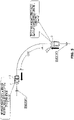
FIG. 2 illustrates an example of the driving state of a convoy including only one following vehicle in the adaptive cruise control system. InFIG. 2 ,lead vehicle 1 is on a straight path after passing through a curve, and followingvehicle 2 is on the curve. - A turning performance unique to following
vehicle 2 is previously set in followingvehicle 2, to prevent at least one of deteriorated ride quality, slipping, and freight collapsing. The turning performance of followingvehicle 2 is set based on the upper limit of a lateral acceleration (lateral acceleration limit) aylim or the upper limit of a yaw rate (yaw rate limit) rlim. To satisfy this turning performance, for the velocity of the followingvehicle 2, an upper limit (maximum allowable vehicle velocity) V2max is set based on the driving path on which followingvehicle 2 runs. Maximum allowable vehicle velocity V2max of followingvehicle 2 is the velocity of followingvehicle 2 when an actual lateral acceleration ay reaches lateral acceleration limit aylim. Alternatively, maximum allowable vehicle velocity V2max of followingvehicle 2 is the velocity of followingvehicle 2 when an actual yaw rate r reaches yaw rate limit rlim of followingvehicle 2. - When following
vehicle 2 is on a driving path having a relatively large curvature, the actual lateral acceleration and the actual yaw rate increase more easily as the vehicle velocity of followingvehicle 2 increases than those when followingvehicle 2 is on a driving path having a relatively small curvature. Thus, when followingvehicle 2 is on a driving path having a relatively large curvature, the actual lateral acceleration and the actual yaw rate of followingvehicle 2 reach lateral acceleration limit aylim and yaw rate limit rlim at a relatively low vehicle velocity. Thus, maximum allowable vehicle velocity V2max of followingvehicle 2 on a driving path having a relatively large curvature is less than maximum allowable vehicle velocity V2max of followingvehicle 2, which is on a driving path that has a relatively small curvature (including a straight path). - Referring back to
FIG. 2 , iflead vehicle 1 accelerates on a straight path after passing through the curve, the velocity (turning velocity) of followingvehicle 2 followinglead vehicle 1 also increases while maintaining a certain inter-vehicle distance therefrom on the curve. If the velocity of followingvehicle 2 exceeds its maximum allowable vehicle velocity V2max on the curve, the actual lateral acceleration or the actual yaw rate of followingvehicle 2 exceeds its upper limit aylim or nlim used to set the turning performance, possibly resulting in deteriorated ride quality, slipping, or freight collapsing. - Thus, following
vehicle 2 calculates its maximum allowable velocity V2max (= u1) that satisfies its turning performance at its driving location and transmits information about maximum allowable velocity V2max (= u1) to leadvehicle 1 via inter-vehicle communication. Next,lead vehicle 1 sets a vehicle velocity limit V1max for controlling its vehicle velocity to the same value as maximum allowable velocity V2max (= u1) and performs vehicle velocity control such that the vehicle velocity will not exceed vehicle velocity limit V1max. In this way, the velocity of followingvehicle 2 does not exceed maximum allowable vehicle velocity V2max, and the actual lateral acceleration and the actual yaw rate of followingvehicle 2 are maintained at or below their respective upper limits aylim and rlim used to set the turning performance. -
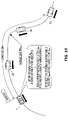
FIG. 3 illustrates an example of the driving state of a convoy including three following vehicles in the adaptive cruise control system. InFIG. 3 ,lead vehicle 1 and a first followingvehicle 2A followinglead vehicle 1 are on a straight path after passing through a curve. A second followingvehicle 2B following first followingvehicle 2A is on the curve, and a third followingvehicle 2C following second followingvehicle 2B is on a straight path before entering the curve. - As in the case of the above convoy including only one following vehicle, each of following
vehicles 2A to 2C calculates its maximum allowable vehicle velocity V2max based on its turning performance at its driving location and transmits information about maximum allowable vehicle velocity V2max to leadvehicle 1 via inter-vehicle communication. Specifically, first followingvehicle 2A calculates its maximum allowable vehicle velocity V2max (= u1) on the straight path on which first followingvehicle 2A is running and transmits information about maximum allowable vehicle velocity V2max (= u1) to leadvehicle 1. Second followingvehicle 2B calculates its maximum allowable vehicle velocity V2max (= u2) on the curve on which second followingvehicle 2B is running and transmits information about maximum allowable vehicle velocity V2max (= u2) to leadvehicle 1. Third followingvehicle 2C calculates its maximum allowable vehicle velocity V2max (= u3) on the straight path on which second followingvehicle 2C is running and transmits information about maximum allowable vehicle velocity V2max (= u3) to leadvehicle 1. - Lead
vehicle 1 sets the lowest one of maximum allowable vehicle velocities V2max of followingvehicles 2A to 2C as vehicle velocity limit V1max. If followingvehicles 2A to 2C have the same turning performance, maximum allowable vehicle velocity V2max (= u2) of second followingvehicle 2B running on the curve is the lowest. Thus,lead vehicle 1 sets maximum allowable vehicle velocity V2max (= u2) of second followingvehicle 2B as vehicle velocity limit V1max and performs vehicle velocity control such that the vehicle velocity oflead vehicle 1 will not exceed vehicle velocity limit V1max set as described above. In this way, the velocities of followingvehicles 2A to 2C are maintained below their respective maximum allowable vehicle velocities V2max, and the actual lateral accelerations and the actual yaw rates of followingvehicles 2A to 2C are maintained at their respective upper limits aylim and rlim or less used to set their respective turning performances. First to third followingvehicles 2A to 2C may have mutually different turning performances. - In short, according to the first example, each of following
vehicles 2 calculates its maximum allowable vehicle velocity V2max that satisfies its turning performance at its driving location, andlead vehicle 1 performs vehicle velocity control so that its vehicle velocity will not exceed vehicle velocity limit V1max set based on maximum allowable vehicle velocities V2max of followingvehicles 2. -
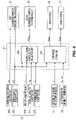
FIG. 4 illustrates an example of an adaptive cruise control system mounted on a following vehicle. The adaptive cruise control system mounted on followingvehicle 2 includes avehicle control apparatus 20 as a main component including a microcomputer as a control unit. The adaptive cruise control system also includes an externalinformation recognition apparatus 21, a vehiclestate acquisition apparatus 22, areception apparatus 23, afirst transmission apparatus 24, asecond transmission apparatus 25, adrive apparatus 26, and abrake apparatus 27. - For example, external
information recognition apparatus 21 recognizes objects present in front of corresponding followingvehicle 2 by using a camera, a radar, a sonar, or the like. Specifically, externalinformation recognition apparatus 21 measures an inter-vehicle distance d between corresponding followingvehicle 2 and its immediately preceding vehicle and outputs information about inter-vehicle distance d. - Vehicle
state acquisition apparatus 22 acquires the vehicle state of corresponding followingvehicle 2 and includes a vehiclevelocity acquisition unit 221, a longitudinalacceleration acquisition unit 222, a yawrate acquisition unit 223, a lateralacceleration acquisition unit 224, and a steeringangle acquisition unit 225. - Vehicle
velocity acquisition unit 221 acquires a vehicle velocity V2 of corresponding followingvehicle 2 based on a vehicle velocity pulse signal output from a vehicle-mounted vehicle velocity sensor or a vehicle velocity estimation result obtained by a vehicle behavior control apparatus such as an ABS (Anti-lock Braking System) and outputs information about vehicle velocity V2. Longitudinalacceleration acquisition unit 222 acquires a longitudinal acceleration ax of corresponding followingvehicle 2 by performing measurement using a vehicle-mounted longitudinal acceleration sensor and outputs information about longitudinal acceleration ax. Longitudinalacceleration acquisition unit 222 may calculate longitudinal acceleration ax based on change of vehicle velocity V2 acquired by vehiclevelocity acquisition unit 221. - Yaw
rate acquisition unit 223 acquires yaw rate r of corresponding followingvehicle 2 by performing measurement, for example, using a vehicle-mounted yaw rate sensor and outputs information about yaw rate r. Yawrate acquisition unit 223 may calculate yaw rate r by using measured values of physical amounts such as vehicle velocity V2 and a steering angle δ, without performing measurement using a yaw rate sensor. Lateralacceleration acquisition unit 224 acquires lateral acceleration ay of corresponding followingvehicle 2 by performing measurement, for example, using a vehicle-mounted lateral acceleration sensor and outputs information about lateral acceleration ay. Lateralacceleration acquisition unit 224 may calculate lateral acceleration ay by using measured values of physical amounts such as vehicle velocity V2 and steering angle δ, without performing measurement using a lateral acceleration sensor. Steeringangle acquisition unit 225 acquires steeringangle 8 of corresponding followingvehicle 2 by performing measurement, for example, using a vehicle-mounted steering angle sensor and outputs information about steering angle δ. -
Reception apparatus 23 receives, from the immediately preceding vehicle of corresponding followingvehicle 2, information about a velocity Vf of the immediately preceding vehicle (immediately preceding vehicle velocity) via inter-vehicle communication between followingvehicle 2 and the immediately preceding vehicle in accordance with an instruction fromvehicle control apparatus 20. If followingvehicle 2 is not the last vehicle in a convoy,first transmission apparatus 24 transmits the output information of vehiclevelocity acquisition unit 221 and longitudinalacceleration acquisition unit 222 to the vehicle immediately behind followingvehicle 2 via inter-vehicle communication between corresponding followingvehicle 2 and the vehicle immediately behind following vehicle 2 (the following vehicle) in accordance with an instruction fromvehicle control apparatus 20.Second transmission apparatus 25 transmits, to leadvehicle 1, information about maximum allowable vehicle velocity V2max of corresponding followingvehicle 2 calculated byvehicle control apparatus 20 via inter-vehicle communication between corresponding followingvehicle 2 andlead vehicle 1 in accordance with an instruction fromvehicle control apparatus 20. -
Drive apparatus 26 includes a drive source (an engine, an electric motor, or a combination thereof) that generates driving force for wheels of corresponding followingvehicle 2 and a drive controller that controls the driving force based on an acceleration command fromvehicle control apparatus 20. -
Brake apparatus 27 includes a brake mechanism (a friction brake, a drum brake, or the like) that applies braking force to wheels of corresponding followingvehicle 2, and a brake controller that controls the braking force based on a deceleration command fromvehicle control apparatus 20. - The microcomputer in
vehicle control apparatus 20 includes a processor such as a central processing unit (CPU), a non-volatile memory such as a read-only memory (ROM), a volatile memory such as a random access memory (RAM), and an input-output port, which are connected to a bus. The same applies to various microcomputers, which will be described below. - The microcomputer in
vehicle control apparatus 20 receives various kinds of information output from externalinformation recognition apparatus 21, vehiclestate acquisition apparatus 22, andreception apparatus 23 and outputs calculation results obtained based on various kinds of information tosecond transmission apparatus 25,drive apparatus 26, andbrake apparatus 27.Vehicle control apparatus 20 has two main functions, which are aninter-vehicle control unit 201 that causes corresponding followingvehicle 2 to follow its immediately preceding vehicle while maintaining the inter-vehicle distance between corresponding followingvehicle 2 and the immediately preceding vehicle at a target value and a maximum allowable vehiclevelocity calculation unit 202 that calculates maximum allowable vehicle velocity V2max that satisfies the turning performance of corresponding followingvehicle 2 at an individual driving location. - The individual functions of
vehicle control apparatus 20 are realized by causing, in the microcomputer, the processor to read out a control program from the non-volatile memory to the volatile memory and to execute the control program. Alternatively, the functions ofvehicle control apparatus 20 may be entirely or partly realized by hardware components. The same applies to various vehicle control apparatuses, which will be described below. - To maintain the inter-vehicle distance between corresponding following
vehicle 2 and the immediately preceding vehicle at a target value during convoy driving,inter-vehicle control unit 201 outputs an acceleration command value Acom as an acceleration command to driveapparatus 26, and outputs a deceleration command Dcom as a deceleration command to brakeapparatus 27. The target value of the inter-vehicle distance may be a constant value or a variable value. That is, the target value of the inter-vehicle distance may be changed as the driving state changes. For example, the target value of the inter-vehicle distance may be increased as the vehicle velocity increases.Inter-vehicle control unit 201 calculates acceleration command value Acom in accordance with the following mathematical equation (1), for example.
- In mathematical equation (1), Δx denotes the difference between inter-vehicle distance d acquired based on the output information of external
information recognition apparatus 21 and a target value d∗ of inter-vehicle distance d (Δx = d - d∗). When inter-vehicle distance d is greater than target value d∗, Δx is calculated as a positive value. When inter-vehicle distance d is less than target value d∗, Δx is calculated as a negative value. In addition, Δv denotes the difference between immediately preceding vehicle velocity Vf acquired based on the output information ofreception apparatus 23 and vehicle velocity V2 of corresponding followingvehicle 2 acquired based on the output information of vehicle velocity acquisition unit 221 (Δv = Vf - V2). When the immediately preceding vehicle velocity Vf is faster than vehicle velocity V2 of corresponding followingvehicle 2, Δv is calculated as a positive value. When immediately preceding vehicle velocity Vf is slower than vehicle velocity V2 of corresponding followingvehicle 2, Δv is calculated as a negative value. - In mathematical equation (1), axf denotes the longitudinal acceleration of the immediately preceding vehicle acquired based on the output information of
reception apparatus 23. When the immediately preceding vehicle accelerates and immediately preceding vehicle velocity Vf increases, axf is given as a positive value. When the immediately preceding vehicle decelerates and immediately preceding vehicle velocity Vf decreases, axf is given as a negative value. In addition, Kx and Kv are positive gain constants, which are control constants stored in the non-volatile memory of the microcomputer. - When acceleration command value Acom calculated in accordance with mathematical equation (1) is a positive value,
inter-vehicle control unit 201 outputs acceleration command value Acom as an acceleration command to driveapparatus 26. In contrast, when acceleration command value Acom calculated in accordance with mathematical equation (1) is a negative value,inter-vehicle control unit 201 calculates deceleration command Dcom as Dcorn= |Acom| and calculated outputs deceleration command Dcom as a deceleration command to brakeapparatus 27. - Other than mathematical equation (1),
inter-vehicle control unit 201 may use a different mathematical equation for calculating acceleration command value Acom. For example,inter-vehicle control unit 201 may use a different mathematical equation as needed, depending on a control request. For example,inter-vehicle control unit 201 may use a mathematical equation including a derivative term or an integral term or may modify and use information about longitudinal acceleration axf or immediately preceding vehicle velocity Vf of the immediately preceding vehicle. Alternatively,inter-vehicle control unit 201 may use a mathematical equation that does not use these items of information. - Maximum allowable vehicle
velocity calculation unit 202 calculates maximum allowable vehicle velocity V2max based on lateral acceleration limit aylim or yaw rate limit rlim used to set the turning performance of corresponding followingvehicle 2 and a curvature κ2 of the driving path on which corresponding followingvehicle 2 is running. - Lateral acceleration limit aylim and yaw rate limit rlim can be stored as fixed values in the non-volatile memory of the microcomputer. Alternatively, a vehicle user may specify any values as lateral acceleration limit aylim and yaw rate limit rlim by operating a switch or the like. For example, if lateral acceleration limit aylim or yaw rate limit rlim is defined to prevent slip, lateral acceleration limit aylim or yaw rate limit rlim may be set changeably depending on the road conditions of the driving path. If lateral acceleration limit aylim or yaw rate limit rlim is defined to prevent collapsing of the freight, lateral acceleration limit aylim or yaw rate limit rlim may be set changeably depending on the load weight or load height.
- In accordance with the following mathematical equation (2), maximum allowable vehicle velocity V2max is calculated as the square root of a value obtained by dividing lateral acceleration limit aylim by curvature κ2. Alternatively, in accordance with the following mathematical equation (3), maximum allowable vehicle velocity V2max may be calculated as a value obtained by dividing yaw rate limit rlim by curvature κ2.


- Curvature κ2 of the driving path on which following
vehicle 2 is running is calculated by suitably assigning physical amounts indicating the vehicle state at an actual driving location of followingvehicle 2 to any one of various relational expressions indicating basic motion characteristics of followingvehicle 2. Examples of the physical amounts include vehicle velocity V2, lateral acceleration ay, yaw rate r, and steering angle δ of followingvehicle 2. For example, if vehicle velocity V2 and lateral acceleration ay of followingvehicle 2 at the driving location of followingvehicle 2 have already been acquired, curvature κ2 can be calculated as a value obtained by dividing lateral acceleration ay by the square of vehicle velocity V2 (κ2 = ay/V22). If vehicle velocity V2 and yaw rate r of followingvehicle 2 at the driving location of followingvehicle 2 have already been acquired, curvature κ2 can be calculated as a value obtained by dividing yaw rate r by vehicle velocity V2 (κ2 = r/V2). In addition, if vehicle velocity V2 and steering angle δ of followingvehicle 2 at the driving location of followingvehicle 2 have already been acquired, and a stability factor A and a wheelbase L that are constants unique to followingvehicle 2 are known, curvature κ2can be calculated in accordance with a relational expression (κ2 = δ/(1 + A × V22) × L). - Maximum allowable vehicle
velocity calculation unit 202 may calculate maximum allowable vehicle velocity V2max by using yaw rate r or lateral acceleration ay acquired at the driving location of followingvehicle 2, instead of using curvature κ2 of the driving path on which followingvehicle 2 is running. Specifically, maximum allowable vehiclevelocity calculation unit 202 may calculate maximum allowable vehicle velocity V2max as a value obtained by dividing lateral acceleration limit aylim by yaw rate r in accordance with the following mathematical equation (4) or as a value obtained by dividing lateral acceleration ay by yaw rate limit rlim in accordance with the following mathematical equation (5).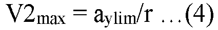

-
Vehicle control apparatus 20 of followingvehicle 2 may use a different method for calculating maximum allowable vehicle velocity V2max as necessary, depending on a specific configuration of vehiclestate acquisition apparatus 22 of followingvehicle 2. After maximum allowable vehiclevelocity calculation unit 202 outputs information about maximum allowable vehicle velocity V2max calculated thereby fromvehicle control apparatus 20 tosecond transmission apparatus 25,second transmission apparatus 25 transmits the information to leadvehicle 1. -
FIG. 5 is a schematic diagram illustrating another example of the adaptive cruise control system of the following vehicle. InFIG. 5 ,lead vehicle 1 is on a straight path after passing through a curve, and a certain followingvehicle 2 is on a straight path before entering the curve. In the above adaptive cruise control system, followingvehicle 2 calculates maximum allowable vehicle velocity V2max that satisfies its turning performance on the straight path on which followingvehicle 2 is actually running. However, in this example, as illustrated inFIG. 5 , followingvehicle 2 calculates its maximum allowable vehicle velocity V2max that satisfies its turning performance on the curve on which followingvehicle 2 is about to enter. That is, followingvehicle 2 calculates its maximum allowable vehicle velocity V2max (= u2) based on curvature (forward curvature) κ2est of the curve into which followingvehicle 2 is about to enter and its turning performance. In addition, whenlead vehicle 1 sets vehicle velocity limit V1max,lead vehicle 1 uses maximum allowable vehicle velocity V2max (= u2). In this way, sincelead vehicle 1 can reduce velocity limit V1max before followingvehicle 2 enters the curve, and the lateral acceleration generated on the curve on which followingvehicle 2 is about to enter is reduced more reliably. - Specifically,
vehicle control apparatus 20 of followingvehicle 2 calculates its maximum allowable vehicle velocity V2max by assigning lateral acceleration limit aylim and forward curvature κ2est in place of curvature κ2 to mathematical equation (2) or by assigning yaw rate limit rlim andforward curvature K2est in place of curvature κ2 to mathematical equation (3). Next,vehicle control apparatus 20 compares maximum allowable vehicle velocity V2max calculated based onforward curvature K2est and the turning performance of followingvehicle 2 with maximum allowable vehicle velocity V2max that satisfies the turning performance of followingvehicle 2 at the driving location on which followingvehicle 2 is actually running. As a result of the comparison, thevehicle control apparatus 20 transmits information about the lower one of maximum allowable vehicle velocities V2max to leadvehicle 1. When setting vehicle velocity limit V1max,lead vehicle 1 uses the lower maximum allowable vehicle velocity V2max. - Forward curvature κ2est can be estimated based on external information recognized by external
information recognition apparatus 21. For example, if externalinformation recognition apparatus 21 is configured to recognize road demarcation lines (white lines) by processing its camera images, forward curvature κ2est can be estimated from the recognized road demarcation lines. If externalinformation recognition apparatus 21 can acquire a relative location and a relative angle, in addition to inter-vehicle distance d between corresponding followingvehicle 2 and the immediately preceding vehicle thereof, by processing its camera images, forward curvature κ2est can be estimated based on a curve obtained by interpolation as the driving path of the immediately preceding vehicle from the acquired data. In another example, from the acquired data, a line extending in the front-back direction of corresponding followingvehicle 2 and a line extending in the front-back direction of the immediately preceding vehicle on a two-dimensional plane are determined, and forward curvature κ2est can be estimated based on a curve that is into contact with these lines and that connects corresponding followingvehicle 2 and the immediately preceding vehicle without an inflection point. - In addition, forward curvature κ2est can be estimated by determining the road shape of the forward driving path from map information. For example, if following
vehicle 2 can acquire its vehicle location from a global positioning system (GPS), a locator, or the like, forward curvature κ2est can be estimated by reading out map information about the acquired vehicle location from a map information database and determining the road shape of the forward driving path. - In addition, forward curvature κ2est can be estimated by acquiring past records of the vehicle state of the immediately preceding vehicle. For example,
reception apparatus 23 of corresponding followingvehicle 2 receives physical amounts (longitudinal acceleration ax, lateral acceleration ay, yaw rate r, vehicle velocity V2, etc.) relating to the vehicle state acquired by vehiclestate acquisition apparatus 22 of the immediately preceding vehicle of corresponding followingvehicle 2, and the driving path of the immediately preceding vehicle can be estimated by performing dead reckoning using integral values of these physical amounts. Corresponding followingvehicle 2 can estimate forward curvature κ2est based on the estimated driving path. Alternatively, if the immediately preceding vehicle is configured to acquire and transmit its own vehicle location, corresponding followingvehicle 2 can estimate the driving path from past records of the vehicle location of the immediately preceding vehicle and can estimate forward curvature κ2est based on this estimated driving path. -
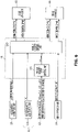
FIG. 6 illustrates an example of an adaptive cruise control system mounted on the lead vehicle. The adaptive cruise control system mounted onlead vehicle 1 includes avehicle control apparatus 10 as a main component including a microcomputer as a control unit. The adaptive cruise control system also includes a vehiclestate acquisition apparatus 11, areception apparatus 12, anaccelerator operation unit 13, abrake operation unit 14, adrive apparatus 15, and abrake apparatus 16. Vehiclestate acquisition apparatus 11 includes a vehiclevelocity acquisition unit 111. Since vehiclevelocity acquisition unit 111 is configured in the same way as vehiclevelocity acquisition unit 221 of followingvehicle 2, description thereof will be omitted. -
Reception apparatus 12 receives information about maximum allowable vehicle velocities V2max(1) to V2max(n) from followingvehicles 2 via inter-vehicle communication with followingvehicles 2 and outputs the information tovehicle control apparatus 10, and n is an integer (a natural number) or 1 or greater for indicating identification numbers of followingvehicles 2. For example, identification numbers are allocated to followingvehicles 2 followinglead vehicle 1 in ascending order via inter-vehicle communication. -
Accelerator operation unit 13 is a mechanism (for example, an accelerator pedal) that receives an acceleration operation amount (for example, an accelerator position) allowing the vehicle user to acceleratelead vehicle 1 and includes an acceleration operation amount sensor (not illustrated) that detects the acceleration operation amount and that outputs information about the acceleration operation amount. The acceleration operation amount is a positive value, and the vehicle velocity oflead vehicle 1 increases as the acceleration operation amount increases. -
Brake operation unit 14 is a mechanism (for example, a brake pedal) that receives a brake operation amount (for example, a brake position) for allowing the vehicle user to deceleratelead vehicle 1 and includes a brake operation amount sensor (not illustrated) that detects the brake operation amount and that outputs information about the brake operation amount. The brake operation amount is a positive value, and the vehicle velocity oflead vehicle 1 decreases as the brake operation amount increases. -
Drive apparatus 15 includes a drive source (an engine, an electric motor, or a combination thereof) that generates driving force for wheels oflead vehicle 1, and a drive controller that controls the driving force based on a control command fromvehicle control apparatus 10.Vehicle control apparatus 10 outputs, to driveapparatus 15, a normal acceleration command or a limited acceleration command as a control command. -
Brake apparatus 16 includes a brake mechanism (a friction brake, a drum brake, or the like) that applies braking force to wheels oflead vehicle 1 and a brake controller that controls the braking force based on a control command output fromvehicle control apparatus 10. Thevehicle control apparatus 10 outputs, to brakeapparatus 16, a normal deceleration command or a forced deceleration command as a control command. - The microcomputer of
vehicle control apparatus 10 receives various kinds of information output from vehiclevelocity acquisition unit 111,reception apparatus 12,accelerator operation unit 13, andbrake operation unit 14 and outputs calculation results obtained based on various kinds of information as control commands to driveapparatus 15 andbrake apparatus 16.Vehicle control apparatus 10 has two main functions, which are a vehicle velocitylimit setting unit 101 and a vehiclevelocity control unit 102. - Vehicle velocity
limit setting unit 101 acquires maximum allowable vehicle velocities V2max(1) to V2max(n) (n is a natural number) of followingvehicles 2 from the output information ofreception apparatus 12 and sets vehicle velocity limit V1max based on maximum allowable vehicle velocities V2max(1) to V2max(n). Specifically, if there is only one followingvehicle 2, vehicle velocitylimit setting unit 101 sets maximum allowable vehicle velocity V2max(1) as vehicle velocity limit V1max. If there are a plurality of followingvehicles 2, vehicle velocitylimit setting unit 101 sets the lowest one of maximum allowable vehicle velocities V2max(1) to V2max(n) (n is a natural number of 2 or more) as vehicle velocity limit V1max. - Vehicle
velocity control unit 102 acquires vehicle velocity V1, the acceleration operation amount, and the brake operation amount from the output information of vehiclevelocity acquisition unit 111,accelerator operation unit 13, andbrake operation unit 14 and outputs control commands generated based on the acceleration operation amount, vehicle velocity V1, vehicle velocity limit V1max, and the brake operation amount to driveapparatus 15 andbrake apparatus 16. Vehiclevelocity control unit 102 performs vehicle velocity control in this way. - Basically, vehicle
velocity control unit 102 outputs a normal acceleration command generated based on an acceleration operation amount associated with an acceleration request from the vehicle user to driveapparatus 15 as a control command. However, when velocity V1 exceeds a predetermined vehicle velocity V1d less than vehicle velocity limit V1max, vehiclevelocity control unit 102 generates a limited acceleration command based on a corrected acceleration operation amount that is less than the acceleration operation amount, to limit the acceleration oflead vehicle 1. Next, vehiclevelocity control unit 102 outputs this limited acceleration command to driveapparatus 15 as a control command. Specifically, if vehicle velocity V1 is between vehicle velocity limit V1max and predetermined vehicle velocity V1d, vehiclevelocity control unit 102 reduces the acceleration operation amount to a value within a range in which leadvehicle 1 can be accelerated. Vehiclevelocity control unit 102 may perform greater reduction from the acceleration operation amount to the corrected acceleration operation amount when the difference (= V1max - V1) between vehicle velocity limit V1max and vehicle velocity V1 is less. If vehicle velocity V1 is over vehicle velocity limit V1max, vehiclevelocity control unit 102 reduces the acceleration operation amount to a value that does not substantially accelerate lead vehicle 1 (for example, 0). - In the case of
vehicle control apparatus 10, predetermined vehicle velocity V1d may be set variably depending on the acceleration operation amount. For example, as the acceleration operation amount increases (that is, as the longitudinal acceleration increases), predetermined vehicle velocity V1d may be separated further from vehicle velocity limit V1max. In the case ofvehicle control apparatus 10, even when vehicle velocity V1 is over predetermined vehicle velocity V1d, if no acceleration operation amount is input, or if the acceleration operation amount is not a value indicating an acceleration request from the vehicle user, outputting of the limited acceleration command can be omitted. - In addition, basically, vehicle
velocity control unit 102 outputs a normal deceleration command generated based on a brake operation amount associated with a brake request from the vehicle user to brakeapparatus 16 as a control command. However, if vehicle velocity V1 exceeds vehicle velocity limit V1max, vehiclevelocity control unit 102 outputs the forced deceleration command as a control command to brakeapparatus 16 for forcibly deceleratinglead vehicle 1, so as to reduce vehicle velocity V1 to vehicle velocity limit V1max or less. The brake operation amount, when the forced deceleration command is output, may be set as a fixed value or a value that varies depending on the excess of vehicle velocity V1 from vehicle velocity limit V1max. - There is a case in which the vehicle user generates a brake request while a forced deceleration command is being output. That is, there may be a situation in which a brake operation amount acquired from the output information of
brake operation unit 14 ofvehicle control apparatus 10 indicates a value indicating a brake request given by the vehicle user. In this situation, if vehiclevelocity control unit 102 predicts that the change by the deceleration oflead vehicle 1 based on the brake operation in accordance with the normal deceleration command will be greater than the change by the deceleration oflead vehicle 1 based on the brake operation in accordance with the forced deceleration command, vehiclevelocity control unit 102 outputs the normal deceleration command to brakeapparatus 16 as a control command. In contrast, if vehiclevelocity control unit 102 predicts that the change by the deceleration oflead vehicle 1 based on the brake operation in accordance with the normal deceleration command will be less than the change by the deceleration oflead vehicle 1 based on the brake operation in accordance with the forced deceleration command, vehiclevelocity control unit 102 continues to output the forced deceleration command to thebrake apparatus 16 as a control command. - The prediction of whether the change by the deceleration based on the brake operation in accordance with the normal deceleration command will be greater than the change by the deceleration based on the brake operation in accordance with the forced deceleration command can be performed as follows. For example, vehicle
velocity control unit 102 can predict which one of the changes will be greater by comparing the brake operation amount that outputs the forced deceleration command with the brake operation amount acquired from the output information ofbrake operation unit 14. - If vehicle
velocity control unit 102 determines that the change by the deceleration based on the brake operation in accordance with the forced deceleration command is the same as the change by the deceleration based on the brake operation in accordance with the normal deceleration command, vehiclevelocity control unit 102 may output either the forced deceleration command or the normal deceleration command as a control command. -
FIG. 7 illustrates a part of an example of processing that realizes maximum allowable vehiclevelocity calculation unit 202 of the vehicle control apparatus of a following vehicle, the processing being included in the control processing repeatedly performed when the ignition switch of the following vehicle is turned on. - In step S1001 (which is abbreviated "S1001" in
FIG. 7 , and the same abbreviation will also apply to the following flowcharts),vehicle control apparatus 20 of followingvehicle 2 calculates maximum allowable vehicle velocity V2max that satisfies the turning performance of followingvehicle 2. Specific methods for calculating maximum allowable vehicle velocity V2max have already been described in the above description of the adaptive cruise control system of followingvehicle 2 and another example thereof. - In step S1002,
vehicle control apparatus 20 of followingvehicle 2 instructssecond transmission apparatus 25 to transmit information about calculated maximum allowable vehicle velocity V2max to leadvehicle 1. -
FIG. 8 illustrates a part of an example of processing that realizes vehicle velocitylimit setting unit 101 and vehiclevelocity control unit 102 of the vehicle control apparatus of a lead vehicle, the processing being included in the control processing repeatedly performed when the ignition switch of the lead vehicle is turned on. - In step S2001,
vehicle control apparatus 10 oflead vehicle 1 instructsreception apparatus 12 to receive information about maximum allowable vehicle velocities V2max(1) to V2max(n) (n is a natural number) from followingvehicles 2. - In step S2002,
vehicle control apparatus 10 oflead vehicle 1 sets vehicle velocity limit V1max based on maximum allowable vehicle velocities V2max(1) to V2max(n) (n is a natural number) of followingvehicles 2 acquired from the output information ofreception apparatus 12. - In step S2003,
vehicle control apparatus 10 oflead vehicle 1 determines whether vehicle velocity V1 is greater than vehicle velocity limit V1max. Ifvehicle control apparatus 10 oflead vehicle 1 determines that vehicle velocity V1 is greater than vehicle velocity limit V1max (YES in step S2003), the processing proceeds to step S2004. However, ifvehicle control apparatus 10 oflead vehicle 1 determines that vehicle velocity V1 is less than or equal to vehicle velocity limit V1max (NO in step S2003), the processing proceeds to step S2007. - In step S2004,
vehicle control apparatus 10 oflead vehicle 1 outputs a limited acceleration command to driveapparatus 15. As described above, the limited acceleration command is generated based on a corrected acceleration operation amount obtained by reducing the acceleration operation amount associated with the acceleration request from the vehicle user to a value that does not substantially acceleratelead vehicle 1. - In step S2005,
vehicle control apparatus 10 oflead vehicle 1 outputs a forced deceleration command to brakeapparatus 16. In step S2006,vehicle control apparatus 10 oflead vehicle 1 determines whether outputting the forced deceleration command is appropriate. A specific processing content of this determination of whether outputting the forced deceleration command is appropriate will be described below. - In step S2007,
vehicle control apparatus 10 oflead vehicle 1 determines whether vehicle velocity V1 is greater than predetermined vehicle velocity V1d. Ifvehicle control apparatus 10 oflead vehicle 1 determines that vehicle velocity V1 is greater than predetermined vehicle velocity V1d (YES in step S2007), the processing proceeds to step S2008. However, ifvehicle control apparatus 10 oflead vehicle 1 determines that vehicle velocity V1 is less than or equal to predetermined vehicle velocity V1d (NO in step S2007),vehicle control apparatus 10 ends the present control processing without limiting vehicle velocity V1. - In step S2008,
vehicle control apparatus 10 oflead vehicle 1 outputs a limited acceleration command to driveapparatus 15. Unlike the limited acceleration command output in step S2004, as described above, the limited acceleration command output in this step is generated based on a corrected acceleration operation amount obtained by reducing the acceleration operation amount associated with the acceleration request from the vehicle user to a value within a range in which leadvehicle 1 can be accelerated. -
FIG. 9 is a subroutine illustrating an example of the determination of whether outputting the forced deceleration command is appropriate in step S2006 included in the control processing inFIG. 8 performed by the vehicle control apparatus of the lead vehicle. - In step S3001,
vehicle control apparatus 10 oflead vehicle 1 determines whether there is a brake request from the vehicle user. As described above, whether there is a brake request from the vehicle user can be determined based on the value of a brake operation amount acquired from the output information ofbrake operation unit 14. - In step S3002,
vehicle control apparatus 10 oflead vehicle 1 determines whether the change by the deceleration oflead vehicle 1 based on the brake operation in accordance with the normal deceleration command is greater than the change by the deceleration oflead vehicle 1 based on the brake operation in accordance with the forced deceleration command. Ifvehicle control apparatus 10 oflead vehicle 1 determines that the change by the deceleration oflead vehicle 1 based on the brake operation in accordance with the normal deceleration command is greater than the change by the deceleration oflead vehicle 1 based on the brake operation in accordance with the forced deceleration command (YES in step S3002),vehicle control apparatus 10 determines that outputting the forced deceleration command is not appropriate, and the processing proceeds to step S3003. In contrast, ifvehicle control apparatus 10 oflead vehicle 1 determines that the change by the deceleration oflead vehicle 1 based on the brake operation in accordance with the normal deceleration command is not greater than the change by the deceleration oflead vehicle 1 based on the brake operation in accordance with the forced deceleration command (NO in step S3002),vehicle control apparatus 10 determines that outputting of the forced deceleration command is appropriate and ends the present subroutine by skipping step S3003. - In step S3003,
vehicle control apparatus 10 oflead vehicle 1 generates the normal deceleration command based on the brake operation amount acquired from the output information ofbrake operation unit 14 and outputs the normal deceleration command, instead of the forced deceleration command, to brakeapparatus 16 as a control command. - As described above, in the adaptive cruise control system according to the first example, each following
vehicle 2 calculates its maximum allowable vehicle velocity V2max that satisfies its turning performance, andlead vehicle 1 calculates vehicle velocity limit V1max based on maximum allowable vehicle velocities V2max transmitted from followingvehicles 2 and performs vehicle velocity control such that vehicle velocity V1 will not exceed vehicle velocity limit V1max. In this way, followingvehicle 2 running on a curve is prevented from experiencing excessively large lateral acceleration that causes at least one of deteriorated ride quality, slipping, and freight collapsing. - Hereinafter, an outline of an adaptive cruise control system according to a second example will be described with reference to
FIG. 10 . The present example will focus on the difference from the first example. The same components in the first and second examples will be denoted by the same reference numerals, and description thereof will be omitted or simplified. -
FIG. 10 illustrates an example of the driving state of a convoy including three following vehicles in the adaptive cruise control system. InFIG. 10 , first followingvehicle 2A, second followingvehicle 2B, and third followingvehicle 2C are non-mechanically connected to leadvehicle 1 sequentially, and each of followingvehicles 2A to 2C follows its immediately preceding vehicle. In the above adaptive cruise control system, each of the followingvehicles 2A to 2C calculates its maximum allowable vehicle velocity V2max that satisfies its turning performance on its driving path on which the corresponding following vehicle is actually running or is about to run. However, in the present example,lead vehicle 1 calculates, for the following vehicles, maximum allowable vehicle velocities V2max that satisfy their respective turning performances on the driving path in the convoy section fromlead vehicle 1 to third followingvehicle 2C, of the entire driving path that leadvehicle 1 has already passed (driven path). - Specifically,
lead vehicle 1 calculates the curvature of the driving path on which leadvehicle 1 is running while sequentially storing the curvature and determines a maximum curvature κmax on the driving path in the convoy section of the entire driven path. Next,lead vehicle 1 calculates maximum allowable vehicle velocity V2max for each of the following vehicles based on maximum curvature κmax and the turning performances of followingvehicles 2A to 2C. Next,lead vehicle 1 sets the lowest one of calculated maximum allowable vehicle velocities V2max of followingvehicles 2A to 2C as vehicle velocity limit V1max and performs vehicle velocity control such that the vehicle velocity will not exceed vehicle velocity limit V1max. Although not illustrated, when only one followingvehicle 2A followslead vehicle 1,lead vehicle 1 sets maximum allowable vehicle velocity V2max calculated based onmaximum curvature κ max1 and the turning performance of followingvehicle 2A as vehicle velocity limit V1max. -
FIG. 11 illustrates an example of an adaptive cruise control system mounted on a following vehicle. The adaptive cruise control system mounted on followingvehicle 2 includes avehicle control apparatus 20a as a main component, externalinformation recognition apparatus 21, a vehiclestate acquisition apparatus 22a,reception apparatus 23,first transmission apparatus 24,second transmission apparatus 25,drive apparatus 26, andbrake apparatus 27. - While
vehicle control apparatus 20a includes a microcomputer as a control unit andinter-vehicle control unit 201 described above as a main function,vehicle control apparatus 20a does not include maximum allowable vehiclevelocity calculation unit 202. In addition,vehicle control apparatus 20a instructssecond transmission apparatus 25 to transmit, instead of information about maximum allowable vehicle velocity V2max, information about inter-vehicle distance d output from externalinformation recognition apparatus 21 to leadvehicle 1. - While vehicle
state acquisition apparatus 22a includes longitudinalacceleration acquisition unit 222 and vehiclevelocity acquisition unit 221 necessary for vehicle velocity control, vehiclestate acquisition apparatus 22a does not include yawrate acquisition unit 223, lateralacceleration acquisition unit 224, and steeringangle acquisition unit 225 necessary for calculating maximum allowable vehicle velocity V2max. -
FIG. 12 illustrates an example of an adaptive cruise control system mounted on the lead vehicle. The adaptive cruise control system mounted onlead vehicle 1 includes avehicle control apparatus 10a as a main component including a microcomputer as a control unit. The adaptive cruise control system also includes a vehiclestate acquisition apparatus 11a,reception apparatus 12,accelerator operation unit 13,brake operation unit 14,drive apparatus 15, andbrake apparatus 16. In addition to vehiclevelocity acquisition unit 111, vehiclestate acquisition apparatus 11a includes a yawrate acquisition unit 112, a lateralacceleration acquisition unit 113, and a steeringangle acquisition unit 114. - Because yaw
rate acquisition unit 112, lateralacceleration acquisition unit 113, and steeringangle acquisition unit 114 are configured in the same way as yawrate acquisition unit 223, lateralacceleration acquisition unit 224, and steeringangle acquisition unit 225 of followingvehicle 2 according to the first example, description thereof will be omitted. - The microcomputer of
vehicle control apparatus 10a receives various kinds of information output from vehiclestate acquisition apparatus 11a,reception apparatus 12,accelerator operation unit 13, andbrake operation unit 14 and outputs calculation results obtained based on various kinds of information to driveapparatus 15 andbrake apparatus 16 as control commands. - In addition to the two main functions which vehicle velocity
limit setting unit 101 and vehiclevelocity control unit 102 have as described above,vehicle control apparatus 10a has another main function of acquiring information necessary for setting vehicle velocity limit V1max. This function is realized by five units of a drivingdistance acquisition unit 103, a driving pathinformation acquisition unit 104, a driven pathinformation storage unit 105, a convoylength estimation unit 106, and a maximum allowable vehiclevelocity calculation unit 107. - Driving
distance acquisition unit 103 acquires vehicle velocity V1 from the output information of vehiclevelocity acquisition unit 111 and acquires driving distance B oflead vehicle 1 based on vehicle velocity V1. For example, driving distance B oflead vehicle 1 can be acquired by multiplying vehicle velocity V1 acquired per control cycle of the microcomputer ofvehicle control apparatus 10a by control cycle time and by adding up the calculated products. - Driving path
information acquisition unit 104 acquires physical amounts indicating the vehicle state at an actual driving location oflead vehicle 1 from the output information of vehiclestate acquisition apparatus 11a and acquires, based on these physical amounts, information about the shape of the driving path at the actual driving location of lead vehicle 1 (driving path information). - Examples of the driving path information include a curvature κ1 of the driving path at the driving location of
lead vehicle 1. Curvature κ1 is calculated by suitably assigning vehicle velocity V1, lateral acceleration ay, yaw rate r, and steering angle δ to any one of various relational expressions indicating basic motion characteristics oflead vehicle 1. Because these various relational expressions indicating basic motion characteristics oflead vehicle 1 are the same as those used for calculating curvature κ2 of the driving path on which followingvehicle 2 is running according to the first example, description thereof will be omitted. Regarding various relational expressions that leadvehicle 1 uses to calculate curvature κ1, a suitable relational expression may be selected depending on which acquisition units are included in vehiclestate acquisition apparatus 11a oflead vehicle 1. - For example, there are cases in which there is only one following
vehicle 2, the convoy section is relatively short, orlead vehicle 1 has run at a constant velocity on the driving path in the convoy section. In any one of these cases, it can be assumed that the vehicle velocity oflead vehicle 1 has not changed much from the location of followingvehicle 2 at the end of the convoy to the location oflead vehicle 1 and that the vehicle velocity oflead vehicle 1 has been constant on the driving path in the convoy section. Thus, in these cases, it is reasonable to say that the individual values of the yaw rate, the lateral acceleration, and the steering angle acquired on the driving path in the convoy section indirectly indicate curvature κ1 on the driving path in the convoy section. Thus, when the vehicle velocity oflead vehicle 1 can be regarded as being constant on the driving path in the convoy section, yaw rate r or lateral acceleration ay acquired by vehiclestate acquisition unit 11a may be acquired as the driving path information, instead of curvature κ1. - Each time that driven path
information storage unit 105 acquires driving distance B and driving path information, driven pathinformation storage unit 105 associates driving distance B with the driving path information and stores the associated information as driven path information in the volatile memory or the like of the microcomputer. The driven path information is information about the shape of the driving path on which leadvehicle 1 has already run. - Convoy
length estimation unit 106 estimates a convoy length C corresponding to the length of the convoy section based on inter-vehicle distances d(1) to d(n) (n is a natural number) acquired from the output information ofreception apparatus 12. As described above, n is a natural number for indicating identification numbers of followingvehicles 2. Specifically, while convoylength estimation unit 106 estimates convoy length C based on a sum of inter-vehicle distances d(1) to d(n) (n is a natural number), if the vehicle length of followingvehicle 2 is known, this vehicle length may be added to convoy length C. - Maximum allowable vehicle
velocity calculation unit 107 sets maximum allowable vehicle velocity V2max as follows, based on driving distance B acquired by drivingdistance acquisition unit 103, the driven path information stored in driven pathinformation storage unit 105, and convoy length C estimated by convoylength estimation unit 106. - First, maximum allowable vehicle
velocity calculation unit 107 subtracts convoy length C from driving distance B oflead vehicle 1 and determines a driving distance Bend oflead vehicle 1, driving distance Bend corresponding to the driving location of the last vehicle in the convoy. Next, maximum allowable vehiclevelocity calculation unit 107 refers to the driven path information and determines maximum curvature κmax on the driving path in the convoy section from curvatures κ1 from driving distance B to driving distance Bend. To save memory resources, of all the driven path information stored in the volatile memory or the like, driven path information less than driving distance Bend may be deleted. - Next, maximum allowable vehicle
velocity calculation unit 107 calculates maximum allowable vehicle velocity V2max for each of followingvehicles 2 based on maximum curvature κmax and the turning performance of corresponding followingvehicles 2. Maximum allowable vehiclevelocity calculation unit 107 may calculate maximum allowable vehicle velocity V2max by replacing curvature κ2 in mathematical equation (2) or mathematical equation (3) by maximum curvature κmax. That is, maximum allowable vehiclevelocity calculation unit 107 may calculate maximum allowable vehicle velocity V2max as the square root of a value obtained by dividing lateral acceleration limit aylim by maximum curvature κmax or a value obtained by dividing yaw rate limit rlim by maximum curvature κmax. If a plurality of followingvehicles 2 have the same turning performance, maximum allowable vehiclevelocity calculation unit 107 may calculate maximum allowable vehicle velocity V2max for only one followingvehicle 2, without calculating maximum allowable vehicle velocity V2max for each followingvehicle 2. - If driving path
information acquisition unit 104 has acquired yaw rate r or lateral acceleration ay as the driving path information, maximum allowable vehiclevelocity calculation unit 107 refers to the driven path information and determines the maximum value of yaw rate r or lateral acceleration ay on the driving path in the convoy section. This is because it is conceivable, when yaw rate r or lateral acceleration ay on the driving path in the convoy section reaches its maximum value, the curvature on the driving path in the convoy section reaches maximum curvature κmax. Next, maximum allowable vehiclevelocity calculation unit 107 assigns the maximum value of yaw rate r to mathematical equation (4) or the maximum value of lateral acceleration ay to mathematical equation (5), to calculate maximum allowable vehicle velocity V2max for each followingvehicle 2. - Vehicle velocity
limit setting unit 101 sets vehicle velocity limit V1max based on maximum allowable vehicle velocities V2max(1) to V2max(n) (n is a natural number) of followingvehicles 2 calculated by maximum allowable vehiclevelocity calculation unit 107. Specifically, if there is only one followingvehicle 2, vehicle velocitylimit setting unit 101 sets maximum allowable vehicle velocity V2max(1) as vehicle velocity limit V1max. If there are a plurality of followingvehicles 2, vehicle velocitylimit setting unit 101 sets the lowest one of maximum allowable vehicle velocities V2max(1) to V2max(n) (n is a natural number of 2 or greater) as vehicle velocity limit V1max. - Vehicle
velocity control unit 102 acquires vehicle velocity V1, the acceleration operation amount, and the brake operation amount from the output information of vehiclevelocity acquisition unit 111,accelerator operation unit 13, andbrake operation unit 14 and outputs control commands generated based on the acceleration operation amount, vehicle velocity V1, vehicle velocity limit V1max, and the brake operation amount to driveapparatus 15 andbrake apparatus 16. Vehiclevelocity control unit 102 performs vehicle velocity control in this way. Since other specific contents about vehiclevelocity control unit 102 are the same as those according to the first example, description thereof will be omitted. -
FIG. 13 illustrates a part of an example of a main part of the control processing repeatedly performed by the vehicle control apparatus of a following vehicle when the ignition switch of the following vehicle is turned on. The processing that realizesinter-vehicle control unit 201, the processing being included in the main part, is not included in this example. - In step S4001,
vehicle control apparatus 20a of followingvehicle 2 acquires inter-vehicle distance d from its immediately preceding vehicle from the output information of externalinformation recognition apparatus 21. - In step S4002,
vehicle control apparatus 20a of followingvehicle 2 instructssecond transmission apparatus 25 to transmit information about inter-vehicle distance d to leadvehicle 1. -
FIG. 14 illustrates a part of an example of processing that realizes the above main functions of all the control processing repeatedly performed by the vehicle control apparatus of a lead vehicle when the ignition switch of the lead vehicle is turned on. - In step S5001,
vehicle control apparatus 10a oflead vehicle 1 acquires vehicle velocity V1 from the output information of vehiclevelocity acquisition unit 111 and calculates driving distance B based on vehicle velocity V1. - In step S5002,
vehicle control apparatus 10a oflead vehicle 1 acquires physical amounts indicating the vehicle state at its actual driving location from the output information of vehiclestate acquisition apparatus 11a and acquires driving path information (for example, curvature κ1) from the physical amounts. Step S5002 may be performed before step S5001. - In step S5003,
vehicle control apparatus 10a oflead vehicle 1 associates the driving path information acquired in step S5002 with driving distance B acquired in step S5001 and stores the associated information in the volatile memory or the like of the microcomputer as driven path information. - In step S5004,
vehicle control apparatus 10a oflead vehicle 1 estimates convoy length C based on inter-vehicle distances d(1) to d(n) (n is a natural number) acquired from the output information ofreception apparatus 12. Step S5004 may be performed before step S5003. - In step S5005,
vehicle control apparatus 10a oflead vehicle 1 calculates maximum allowable vehicle velocities V2max based on driving distance B acquired in step S5001, convoy length C estimated in step S5002, and driven path information stored in step S5003. Since specific methods for calculating maximum allowable vehicle velocity V2max are the same are those described with maximum allowable vehiclevelocity calculation unit 107, description thereof will be omitted. - In step S5006,
vehicle control apparatus 10a oflead vehicle 1 sets vehicle velocity limit V1max based on maximum allowable vehicle velocities V2max(1) to V2max(n) (n is a natural number) of followingvehicles 2 calculated in step S5005. Since steps S5007 to S5012 are the same as steps S2003 to S2008, description thereof will be omitted. - As described above, while each following
vehicle 2 measures inter-vehicle distance d from its immediately preceding vehicle so thatlead vehicle 1 can estimate convoy length C, inter-vehicle distance d may be measured in a different way. For example, if there is only one followingvehicle 2,lead vehicle 1 can measure inter-vehicle distance d from followingvehicle 2 by using a rear side recognition apparatus that can recognize objects behindlead vehicle 1. In this way, followingvehicle 2 does not need to transmit information about inter-vehicle distance d to leadvehicle 1. If there are a plurality of followingvehicles 2, in addition to havelead vehicle 1 measure inter-vehicle distance d from the vehicle immediately followinglead vehicle 1 by using a rear side recognition apparatus, each followingvehicle 2 may measure inter-vehicle distance d from the vehicle immediately following this followingvehicle 2 by using a rear side recognition apparatus equivalent to that oflead vehicle 1. In this way, the last vehicle in the convoy does not need to transmit information about inter-vehicle distance d to leadvehicle 1. - When the target value of the inter-vehicle distance in the inter-vehicle control unit of following
vehicle 2 is a constant value and when actual convoy length C will not probably change by the inter-vehicle control,vehicle control apparatus 10a oflead vehicle 1 may be configured without convoylength estimation unit 106. In this case, maximum allowable vehiclevelocity calculation unit 107 ofvehicle control apparatus 10a oflead vehicle 1 calculates maximum allowable vehicle velocity V2max assuming that convoy length C is a known fixed value stored in advance in the non-volatile memory or the like of the microcomputer. - As described above, in the adaptive cruise control system according to the second example,
lead vehicle 1 calculates maximum allowable vehicle velocities V2max based on maximum curvature κmax of the driving path in the convoy section in the driven path and the turning performances of followingvehicles 2. Next,lead vehicle 1 sets vehicle velocity limit V1max based on maximum allowable vehicle velocities V2max of followingvehicles 2 and performs vehicle velocity control such that the vehicle velocity oflead vehicle 1 will not exceed vehicle velocity limit V1max. In this way, in addition to preventing followingvehicle 2 on a curve from experiencing excessively large lateral acceleration that causes at least one of deteriorated ride quality, slipping, and freight collapsing, the following significant advantageous effects can be provided. That is, followingvehicles 2 do not need to calculate maximum allowable vehicle velocities V2max. In addition, when the convoy length will not probably change, each followingvehicle 2 does not need transmit information about inter-vehicle distance d. Thus, since followingvehicle 2 has less processing load, calculation resources can be allocated to other control processing such inter-vehicle control processing. - As describe above, in
FIG. 12 , maximum allowable vehiclevelocity calculation unit 107 calculates maximum allowable vehicle velocities V2max of followingvehicles 2 and supplies calculated maximum allowable vehicle velocities V2max to vehicle velocitylimit setting unit 101, which then calculates vehicle velocity limit V1max. However, alternatively, vehicle velocity limit V1max may directly be determined based on the driven path information stored in driven pathinformation storage unit 105. - Although the present invention has thus been described in detail with reference to preferable examples, the individual technical concepts described in the above first and second examples can be appropriately combined and used as long as there is no conflict. In addition, it is apparent to those skilled in the art that various types of modifications, as described below, are possible, based on the basic technical concept and teaching of the present invention.
- In the above first and second examples,
lead vehicle 1 sets vehicle velocity limit V1max based on maximum allowable vehicle velocities V2max of followingvehicles 2 and performs vehicle velocity control such that the vehicle velocity oflead vehicle 1 will not exceed vehicle velocity limit V1max. Alternatively,lead vehicle 1 may simply perform vehicle velocity control such thatlead vehicle 1 does not accelerate when followingvehicle 2 enters a curve. For example, when followingvehicle 2 determines that followingvehicle 2 has entered a curve based on the output information of yawrate acquisition unit 223, lateralacceleration acquisition unit 224, or steeringangle acquisition unit 225, followingvehicle 2 transmits a limitation request signal requestinglead vehicle 1 to limit the vehicle velocity oflead vehicle 1. Upon receiving this limitation request signal,lead vehicle 1 performs vehicle velocity control that prevents acceleration oflead vehicle 1. In this way, it is possible to reduce the risk that followingvehicle 2 on a curve will experience excessively large lateral acceleration that causes at least one of deteriorated ride quality, slipping, and freight collapsing. - In the above first and second examples, the processing for determining whether outputting the forced deceleration command is appropriate is performed in a predetermined step in the control processing of
lead vehicle 1. However, alternatively, this determination processing may be performed as interrupt processing performed when a brake request is issued from the vehicle user while the forced deceleration command is being output. - In each of the above adaptive cruise control systems of following
vehicles 2, for convenience of description of the functions, three functions that perform inter-vehicle communication have been described. However,reception apparatus 23,first transmission apparatus 24, andsecond transmission apparatus 25 may be configured as a single communication apparatus. - In each of the above adaptive cruise control systems of
lead vehicles 1, vehiclevelocity control unit 102 selects the normal acceleration command or the limited acceleration command and selects the normal deceleration command or the forced deceleration command. However, the drive controller ofdrive apparatus 15 may select the normal acceleration command fromaccelerator operation unit 13 or the limited acceleration command from vehiclevelocity control unit 102, and the brake controller ofbrake apparatus 16 may select the normal deceleration command frombrake operation unit 14 or the forced deceleration command from vehiclevelocity control unit 102. -
- 1
- lead vehicle
- 10, 10a
- vehicle control apparatus
- 12
- reception apparatus
- 13
- accelerator operation unit
- 14
- brake operation unit
- 15
- drive apparatus
- 16
- brake apparatus
- 101
- vehicle velocity limit setting unit
- 102
- vehicle velocity control unit
- 103
- driving distance acquisition unit
- 104
- driving path information acquisition unit
- 105
- driven path information storage unit
- 106
- convoy length estimation unit
- 107
- maximum allowable vehicle velocity calculation unit
- 111
- vehicle velocity acquisition unit
- 112
- yaw rate acquisition unit
- 113
- lateral acceleration acquisition unit
- 114
- steering angle acquisition unit
- 2, 2A, 2B, 2C
- following vehicle
- 20, 20a
- vehicle control apparatus
- 21
- external information recognition apparatus
- 25
- second transmission apparatus
- 202
- maximum allowable vehicle velocity calculation unit
- 221
- vehicle velocity acquisition unit
- 223
- yaw rate acquisition unit
- 224
- lateral acceleration acquisition unit
- 225
- steering angle acquisition unit
- ay
- lateral acceleration
- aylim
- lateral acceleration limit
- r
- yaw rate
- rlim
- yaw rate limit
- V1
- vehicle velocity of lead vehicle
- V1d
- predetermined vehicle velocity
- V1max
- vehicle velocity limit
- V2max
- maximum allowable vehicle velocity of following vehicle
- κ1
- curvature at driving location of lead vehicle
- κmax
- maximum curvature of driving path in convoy section
- κ2
- curvature at driving location of following vehicle
- κ2est
- forward curvature of following vehicle
Claims (14)
- A vehicle control apparatus comprising:a control unit which is mounted on a lead vehicle in an adaptive cruise control system that non-mechanically connects a following vehicle to the lead vehicle sequentially and that causes the following vehicle to follow its immediately preceding vehicle and which outputs a calculation result obtained based on input information to a brake apparatus or a drive apparatus as a control command,wherein the control unit calculates a vehicle velocity limit for limiting a velocity of the lead vehicle based on a maximum allowable vehicle velocity of the following vehicle, the maximum allowable vehicle velocity satisfying a turning performance of the following vehicle, andwherein the control unit outputs the control command to the brake apparatus and/or the drive apparatus such that the velocity of the lead vehicle will not exceed the vehicle velocity limit.
- The vehicle control apparatus according to claim 1,
wherein the following vehicle calculates the maximum allowable vehicle velocity, and the control unit acquires the maximum allowable vehicle velocity from the following vehicle. - The vehicle control apparatus according to claim 2, wherein, when the velocity of the lead vehicle exceeds a predetermined vehicle velocity lower than the vehicle velocity limit, the control unit outputs a limited acceleration command for limiting acceleration of the lead vehicle to the drive apparatus as the control command.
- The vehicle control apparatus according to claim 2, wherein when the velocity of the lead vehicle is higher than the vehicle velocity limit, the control unit outputs a forced deceleration command for forcibly decelerating the lead vehicle to the brake apparatus as the control command.
- The vehicle control apparatus according to claim 4, wherein, when a brake operation amount associated with a brake request from a vehicle user is input while the forced deceleration command is being output, if the control unit determines that change by deceleration of the lead vehicle by a brake operation in accordance with the brake request from the vehicle user is greater than change by deceleration of the lead vehicle by a brake operation in accordance with the forced deceleration command, the control unit outputs a deceleration command generated based on the brake operation amount to the brake apparatus as the control command.
- The vehicle control apparatus according to claim 2, wherein the turning performance of the following vehicle is an allowable lateral acceleration upper limit of the following vehicle.
- The vehicle control apparatus according to claim 2, wherein the turning performance of the following vehicle is an allowable yaw rate upper limit of the following vehicle.
- The vehicle control apparatus according to claim 2, wherein the maximum allowable vehicle velocity is calculated based on a curvature of a driving path on which the following vehicle runs.
- The vehicle control apparatus according to claim 2, wherein the maximum allowable vehicle velocity is calculated based on the turning performance of the following vehicle and a physical amount indicating a shape of a driving path on which the following vehicle is turning or a physical amount indicating a vehicle state of the following vehicle that is turning.
- The vehicle control apparatus according to claim 2, wherein the maximum allowable vehicle velocity is calculated based on the turning performance of the following vehicle and a physical amount indicating a shape of a driving path on which the following vehicle is predicted to run.
- The vehicle control apparatus according to claim 1, wherein the control unit sets the vehicle velocity limit based on the turning performance of the following vehicle and information about a shape of a driving path on which the lead vehicle has already run.
- The vehicle control apparatus according to claim 1, wherein the following vehicle is provided in plurality, and the control unit sets a lowest one of the maximum allowable vehicle velocities calculated for the plurality of following vehicles as the vehicle velocity limit.
- A vehicle control method for a lead vehicle in an adaptive cruise control system that non-mechanically connects a following vehicle to the lead vehicle sequentially and that causes the following vehicle to follow its immediately preceding vehicle, the vehicle control method comprising:calculating a vehicle velocity limit for limiting a velocity of the lead vehicle based on a maximum allowable vehicle velocity of the following vehicle, the maximum allowable vehicle velocity satisfying a turning performance of the following vehicle; andcontrolling a brake apparatus and/or a drive apparatus such that the velocity of the lead vehicle will not exceed the vehicle velocity limit.
- An adaptive cruise control system that non-mechanically connects a following vehicle to a lead vehicle sequentially and that causes the following vehicle to follow its immediately preceding vehicle, wherein the lead vehicle comprises:a control unit that calculates a vehicle velocity limit for limiting a velocity of the lead vehicle based on a maximum allowable vehicle velocity of the following vehicle, the maximum allowable vehicle velocity satisfying a turning performance of the following vehicle, and that outputs a control command for limiting acceleration or deceleration of the lead vehicle such that the velocity of the lead vehicle will not exceed the vehicle velocity limit;a brake apparatus that controls braking force based on the control command; anda drive apparatus that controls driving force based on the control command.
Applications Claiming Priority (2)
| Application Number | Priority Date | Filing Date | Title |
|---|---|---|---|
| JP2020009097 | 2020-01-23 | ||
| PCT/JP2021/002054 WO2021149768A1 (en) | 2020-01-23 | 2021-01-21 | Vehicle control deice, vehicle control method, and vehicle following system |
Publications (2)
| Publication Number | Publication Date |
|---|---|
| EP4095004A1 true EP4095004A1 (en) | 2022-11-30 |
| EP4095004A4 EP4095004A4 (en) | 2023-07-19 |
Family
ID=76992544
Family Applications (1)
| Application Number | Title | Priority Date | Filing Date |
|---|---|---|---|
| EP21743655.9A Pending EP4095004A4 (en) | 2020-01-23 | 2021-01-21 | Vehicle control device, vehicle control method, and vehicle following system |
Country Status (5)
| Country | Link |
|---|---|
| US (1) | US20230073287A1 (en) |
| EP (1) | EP4095004A4 (en) |
| JP (1) | JP7465286B2 (en) |
| CN (1) | CN115023378A (en) |
| WO (1) | WO2021149768A1 (en) |
Families Citing this family (2)
| Publication number | Priority date | Publication date | Assignee | Title |
|---|---|---|---|---|
| JP2021142905A (en) * | 2020-03-12 | 2021-09-24 | 本田技研工業株式会社 | Vehicle follow-up travel system, information processing method, and program |
| CN114013457A (en) * | 2021-11-19 | 2022-02-08 | 长沙智能驾驶研究院有限公司 | Vehicle control method, device, equipment and computer storage medium |
Family Cites Families (5)
| Publication number | Priority date | Publication date | Assignee | Title |
|---|---|---|---|---|
| JP5023894B2 (en) | 2007-08-31 | 2012-09-12 | トヨタ自動車株式会社 | Travel plan generator |
| JP2010030525A (en) * | 2008-07-30 | 2010-02-12 | Toyota Motor Corp | Travel support device |
| JP5760835B2 (en) * | 2011-08-10 | 2015-08-12 | 株式会社デンソー | Driving support device and driving support system |
| JP6201473B2 (en) | 2013-07-17 | 2017-09-27 | 日産自動車株式会社 | Vehicle travel control device |
| JP6813433B2 (en) * | 2017-06-13 | 2021-01-13 | 日立オートモティブシステムズ株式会社 | Vehicle motion control device, vehicle motion control method and vehicle motion control system |
-
2021
- 2021-01-21 EP EP21743655.9A patent/EP4095004A4/en active Pending
- 2021-01-21 US US17/794,717 patent/US20230073287A1/en active Pending
- 2021-01-21 CN CN202180010679.0A patent/CN115023378A/en active Pending
- 2021-01-21 JP JP2021572792A patent/JP7465286B2/en active Active
- 2021-01-21 WO PCT/JP2021/002054 patent/WO2021149768A1/en unknown
Also Published As
| Publication number | Publication date |
|---|---|
| WO2021149768A9 (en) | 2022-06-09 |
| JP7465286B2 (en) | 2024-04-10 |
| US20230073287A1 (en) | 2023-03-09 |
| CN115023378A (en) | 2022-09-06 |
| EP4095004A4 (en) | 2023-07-19 |
| WO2021149768A1 (en) | 2021-07-29 |
| WO2021149768A8 (en) | 2022-07-07 |
| JPWO2021149768A1 (en) | 2021-07-29 |
Similar Documents
| Publication | Publication Date | Title |
|---|---|---|
| EP4095004A1 (en) | Vehicle control device, vehicle control method, and vehicle following system | |
| US11110927B2 (en) | System for controlling braking energy regeneration step variable and method thereof | |
| EP2561502B1 (en) | Assessment method and system pertaining to acceleration | |
| US8073606B2 (en) | Vehicle control system | |
| US20180001764A1 (en) | Control method for improving fuel efficiency in adaptive cruise control system when preceding vehicle exists | |
| US9174535B2 (en) | System and apparatus for controlling speed in excess speed enforcement section | |
| US9969394B2 (en) | Distance regulating system, motor vehicle and computer program product | |
| CN111506087A (en) | Self-adaptive car following method, device, equipment and storage medium for automatic driving car | |
| US20220315003A1 (en) | Automated lane changing device and method for vehicle | |
| CN113348121B (en) | Method and control unit for operating an adaptive speed regulator | |
| CN110789524A (en) | Adaptive cruise control | |
| US10882519B2 (en) | Apparatus and method for setting speed of vehicle | |
| CN107428341A (en) | For the method and apparatus for the car speed for being adapted to vehicle | |
| CN113147762A (en) | Control method and device for adaptive cruise, commercial vehicle and storage medium | |
| US20160229401A1 (en) | Vehicle Running Control Apparatus | |
| US11136028B2 (en) | Speed controller for platooning vehicle and method therefor | |
| US20200062251A1 (en) | System and method of determining risk situation of collision of autonomous vehicle | |
| US20220410905A1 (en) | Method and System for Recognizing an Object Which Is Turning Off | |
| CN111572561B (en) | Speed control method, device and equipment for automatic driving automobile and storage medium | |
| CN111497843A (en) | Driving assistance system, and brake control unit and brake control method thereof | |
| CN112455404A (en) | Method, apparatus, storage medium, and device for vehicle brake control | |
| CN112937561A (en) | Vehicle brake assist device | |
| CN115805952A (en) | Safety distance correction method and device for automatic brake auxiliary system | |
| US20220118957A1 (en) | Control device for vehicle, actuator system, control method, non-transitory storage medium, and vehicle | |
| JP2023075502A (en) | Vehicle information processing device, vehicle information processing method and program |
Legal Events
| Date | Code | Title | Description |
|---|---|---|---|
| STAA | Information on the status of an ep patent application or granted ep patent |
Free format text: STATUS: THE INTERNATIONAL PUBLICATION HAS BEEN MADE |
|
| PUAI | Public reference made under article 153(3) epc to a published international application that has entered the european phase |
Free format text: ORIGINAL CODE: 0009012 |
|
| STAA | Information on the status of an ep patent application or granted ep patent |
Free format text: STATUS: REQUEST FOR EXAMINATION WAS MADE |
|
| 17P | Request for examination filed |
Effective date: 20220719 |
|
| AK | Designated contracting states |
Kind code of ref document: A1 Designated state(s): AL AT BE BG CH CY CZ DE DK EE ES FI FR GB GR HR HU IE IS IT LI LT LU LV MC MK MT NL NO PL PT RO RS SE SI SK SM TR |
|
| DAV | Request for validation of the european patent (deleted) | ||
| DAX | Request for extension of the european patent (deleted) | ||
| A4 | Supplementary search report drawn up and despatched |
Effective date: 20230621 |
|
| RIC1 | Information provided on ipc code assigned before grant |
Ipc: G08G 1/00 20060101ALI20230615BHEP Ipc: B60W 30/14 20060101ALI20230615BHEP Ipc: B60W 30/188 20120101ALI20230615BHEP Ipc: B60W 30/165 20200101ALI20230615BHEP Ipc: B60T 7/12 20060101AFI20230615BHEP |