EP4094966A1 - Electric truck - Google Patents
Electric truck Download PDFInfo
- Publication number
- EP4094966A1 EP4094966A1 EP20917253.5A EP20917253A EP4094966A1 EP 4094966 A1 EP4094966 A1 EP 4094966A1 EP 20917253 A EP20917253 A EP 20917253A EP 4094966 A1 EP4094966 A1 EP 4094966A1
- Authority
- EP
- European Patent Office
- Prior art keywords
- pair
- electric truck
- steering
- vehicle
- motor
- Prior art date
- Legal status (The legal status is an assumption and is not a legal conclusion. Google has not performed a legal analysis and makes no representation as to the accuracy of the status listed.)
- Pending
Links
Images


Classifications
-
- B—PERFORMING OPERATIONS; TRANSPORTING
- B60—VEHICLES IN GENERAL
- B60G—VEHICLE SUSPENSION ARRANGEMENTS
- B60G11/00—Resilient suspensions characterised by arrangement, location or kind of springs
- B60G11/26—Resilient suspensions characterised by arrangement, location or kind of springs having fluid springs only, e.g. hydropneumatic springs
- B60G11/27—Resilient suspensions characterised by arrangement, location or kind of springs having fluid springs only, e.g. hydropneumatic springs wherein the fluid is a gas
-
- B—PERFORMING OPERATIONS; TRANSPORTING
- B60—VEHICLES IN GENERAL
- B60K—ARRANGEMENT OR MOUNTING OF PROPULSION UNITS OR OF TRANSMISSIONS IN VEHICLES; ARRANGEMENT OR MOUNTING OF PLURAL DIVERSE PRIME-MOVERS IN VEHICLES; AUXILIARY DRIVES FOR VEHICLES; INSTRUMENTATION OR DASHBOARDS FOR VEHICLES; ARRANGEMENTS IN CONNECTION WITH COOLING, AIR INTAKE, GAS EXHAUST OR FUEL SUPPLY OF PROPULSION UNITS IN VEHICLES
- B60K7/00—Disposition of motor in, or adjacent to, traction wheel
- B60K7/0007—Disposition of motor in, or adjacent to, traction wheel the motor being electric
-
- B—PERFORMING OPERATIONS; TRANSPORTING
- B60—VEHICLES IN GENERAL
- B60G—VEHICLE SUSPENSION ARRANGEMENTS
- B60G11/00—Resilient suspensions characterised by arrangement, location or kind of springs
- B60G11/26—Resilient suspensions characterised by arrangement, location or kind of springs having fluid springs only, e.g. hydropneumatic springs
- B60G11/28—Resilient suspensions characterised by arrangement, location or kind of springs having fluid springs only, e.g. hydropneumatic springs characterised by means specially adapted for attaching the spring to axle or sprung part of the vehicle
-
- B—PERFORMING OPERATIONS; TRANSPORTING
- B60—VEHICLES IN GENERAL
- B60G—VEHICLE SUSPENSION ARRANGEMENTS
- B60G11/00—Resilient suspensions characterised by arrangement, location or kind of springs
- B60G11/32—Resilient suspensions characterised by arrangement, location or kind of springs having springs of different kinds
- B60G11/48—Resilient suspensions characterised by arrangement, location or kind of springs having springs of different kinds not including leaf springs
- B60G11/56—Resilient suspensions characterised by arrangement, location or kind of springs having springs of different kinds not including leaf springs having helical, spiral or coil springs, and also fluid springs
- B60G11/58—Resilient suspensions characterised by arrangement, location or kind of springs having springs of different kinds not including leaf springs having helical, spiral or coil springs, and also fluid springs arranged coaxially
-
- B—PERFORMING OPERATIONS; TRANSPORTING
- B60—VEHICLES IN GENERAL
- B60G—VEHICLE SUSPENSION ARRANGEMENTS
- B60G15/00—Resilient suspensions characterised by arrangement, location or type of combined spring and vibration damper, e.g. telescopic type
- B60G15/02—Resilient suspensions characterised by arrangement, location or type of combined spring and vibration damper, e.g. telescopic type having mechanical spring
- B60G15/06—Resilient suspensions characterised by arrangement, location or type of combined spring and vibration damper, e.g. telescopic type having mechanical spring and fluid damper
- B60G15/062—Resilient suspensions characterised by arrangement, location or type of combined spring and vibration damper, e.g. telescopic type having mechanical spring and fluid damper the spring being arranged around the damper
-
- B—PERFORMING OPERATIONS; TRANSPORTING
- B60—VEHICLES IN GENERAL
- B60K—ARRANGEMENT OR MOUNTING OF PROPULSION UNITS OR OF TRANSMISSIONS IN VEHICLES; ARRANGEMENT OR MOUNTING OF PLURAL DIVERSE PRIME-MOVERS IN VEHICLES; AUXILIARY DRIVES FOR VEHICLES; INSTRUMENTATION OR DASHBOARDS FOR VEHICLES; ARRANGEMENTS IN CONNECTION WITH COOLING, AIR INTAKE, GAS EXHAUST OR FUEL SUPPLY OF PROPULSION UNITS IN VEHICLES
- B60K17/00—Arrangement or mounting of transmissions in vehicles
- B60K17/04—Arrangement or mounting of transmissions in vehicles characterised by arrangement, location, or kind of gearing
- B60K17/043—Transmission unit disposed in on near the vehicle wheel, or between the differential gear unit and the wheel
-
- B—PERFORMING OPERATIONS; TRANSPORTING
- B62—LAND VEHICLES FOR TRAVELLING OTHERWISE THAN ON RAILS
- B62D—MOTOR VEHICLES; TRAILERS
- B62D13/00—Steering specially adapted for trailers
- B62D13/04—Steering specially adapted for trailers for individually-pivoted wheels
-
- B—PERFORMING OPERATIONS; TRANSPORTING
- B62—LAND VEHICLES FOR TRAVELLING OTHERWISE THAN ON RAILS
- B62D—MOTOR VEHICLES; TRAILERS
- B62D21/00—Understructures, i.e. chassis frame on which a vehicle body may be mounted
- B62D21/02—Understructures, i.e. chassis frame on which a vehicle body may be mounted comprising longitudinally or transversely arranged frame members
-
- B—PERFORMING OPERATIONS; TRANSPORTING
- B60—VEHICLES IN GENERAL
- B60G—VEHICLE SUSPENSION ARRANGEMENTS
- B60G2200/00—Indexing codes relating to suspension types
- B60G2200/40—Indexing codes relating to the wheels in the suspensions
- B60G2200/422—Driving wheels or live axles
-
- B—PERFORMING OPERATIONS; TRANSPORTING
- B60—VEHICLES IN GENERAL
- B60G—VEHICLE SUSPENSION ARRANGEMENTS
- B60G2200/00—Indexing codes relating to suspension types
- B60G2200/40—Indexing codes relating to the wheels in the suspensions
- B60G2200/44—Indexing codes relating to the wheels in the suspensions steerable
-
- B—PERFORMING OPERATIONS; TRANSPORTING
- B60—VEHICLES IN GENERAL
- B60G—VEHICLE SUSPENSION ARRANGEMENTS
- B60G2202/00—Indexing codes relating to the type of spring, damper or actuator
- B60G2202/10—Type of spring
- B60G2202/15—Fluid spring
- B60G2202/152—Pneumatic spring
-
- B—PERFORMING OPERATIONS; TRANSPORTING
- B60—VEHICLES IN GENERAL
- B60G—VEHICLE SUSPENSION ARRANGEMENTS
- B60G2204/00—Indexing codes related to suspensions per se or to auxiliary parts
- B60G2204/10—Mounting of suspension elements
- B60G2204/12—Mounting of springs or dampers
- B60G2204/124—Mounting of coil springs
-
- B—PERFORMING OPERATIONS; TRANSPORTING
- B60—VEHICLES IN GENERAL
- B60G—VEHICLE SUSPENSION ARRANGEMENTS
- B60G2204/00—Indexing codes related to suspensions per se or to auxiliary parts
- B60G2204/10—Mounting of suspension elements
- B60G2204/12—Mounting of springs or dampers
- B60G2204/126—Mounting of pneumatic springs
-
- B—PERFORMING OPERATIONS; TRANSPORTING
- B60—VEHICLES IN GENERAL
- B60G—VEHICLE SUSPENSION ARRANGEMENTS
- B60G2300/00—Indexing codes relating to the type of vehicle
- B60G2300/02—Trucks; Load vehicles
- B60G2300/026—Heavy duty trucks
- B60G2300/0262—Multi-axle trucks
-
- B—PERFORMING OPERATIONS; TRANSPORTING
- B60—VEHICLES IN GENERAL
- B60G—VEHICLE SUSPENSION ARRANGEMENTS
- B60G2300/00—Indexing codes relating to the type of vehicle
- B60G2300/50—Electric vehicles; Hybrid vehicles
-
- B—PERFORMING OPERATIONS; TRANSPORTING
- B60—VEHICLES IN GENERAL
- B60K—ARRANGEMENT OR MOUNTING OF PROPULSION UNITS OR OF TRANSMISSIONS IN VEHICLES; ARRANGEMENT OR MOUNTING OF PLURAL DIVERSE PRIME-MOVERS IN VEHICLES; AUXILIARY DRIVES FOR VEHICLES; INSTRUMENTATION OR DASHBOARDS FOR VEHICLES; ARRANGEMENTS IN CONNECTION WITH COOLING, AIR INTAKE, GAS EXHAUST OR FUEL SUPPLY OF PROPULSION UNITS IN VEHICLES
- B60K7/00—Disposition of motor in, or adjacent to, traction wheel
- B60K2007/0038—Disposition of motor in, or adjacent to, traction wheel the motor moving together with the wheel axle
-
- B—PERFORMING OPERATIONS; TRANSPORTING
- B60—VEHICLES IN GENERAL
- B60K—ARRANGEMENT OR MOUNTING OF PROPULSION UNITS OR OF TRANSMISSIONS IN VEHICLES; ARRANGEMENT OR MOUNTING OF PLURAL DIVERSE PRIME-MOVERS IN VEHICLES; AUXILIARY DRIVES FOR VEHICLES; INSTRUMENTATION OR DASHBOARDS FOR VEHICLES; ARRANGEMENTS IN CONNECTION WITH COOLING, AIR INTAKE, GAS EXHAUST OR FUEL SUPPLY OF PROPULSION UNITS IN VEHICLES
- B60K7/00—Disposition of motor in, or adjacent to, traction wheel
- B60K2007/0061—Disposition of motor in, or adjacent to, traction wheel the motor axle being parallel to the wheel axle
-
- B—PERFORMING OPERATIONS; TRANSPORTING
- B60—VEHICLES IN GENERAL
- B60K—ARRANGEMENT OR MOUNTING OF PROPULSION UNITS OR OF TRANSMISSIONS IN VEHICLES; ARRANGEMENT OR MOUNTING OF PLURAL DIVERSE PRIME-MOVERS IN VEHICLES; AUXILIARY DRIVES FOR VEHICLES; INSTRUMENTATION OR DASHBOARDS FOR VEHICLES; ARRANGEMENTS IN CONNECTION WITH COOLING, AIR INTAKE, GAS EXHAUST OR FUEL SUPPLY OF PROPULSION UNITS IN VEHICLES
- B60K7/00—Disposition of motor in, or adjacent to, traction wheel
- B60K2007/0092—Disposition of motor in, or adjacent to, traction wheel the motor axle being coaxial to the wheel axle
-
- B—PERFORMING OPERATIONS; TRANSPORTING
- B60—VEHICLES IN GENERAL
- B60Y—INDEXING SCHEME RELATING TO ASPECTS CROSS-CUTTING VEHICLE TECHNOLOGY
- B60Y2200/00—Type of vehicle
- B60Y2200/10—Road Vehicles
- B60Y2200/14—Trucks; Load vehicles, Busses
- B60Y2200/142—Heavy duty trucks
- B60Y2200/1422—Multi-axle trucks
-
- B—PERFORMING OPERATIONS; TRANSPORTING
- B60—VEHICLES IN GENERAL
- B60Y—INDEXING SCHEME RELATING TO ASPECTS CROSS-CUTTING VEHICLE TECHNOLOGY
- B60Y2200/00—Type of vehicle
- B60Y2200/40—Special vehicles
- B60Y2200/45—Vehicles having steerable wheels mounted on a vertically moving column
-
- B—PERFORMING OPERATIONS; TRANSPORTING
- B62—LAND VEHICLES FOR TRAVELLING OTHERWISE THAN ON RAILS
- B62D—MOTOR VEHICLES; TRAILERS
- B62D21/00—Understructures, i.e. chassis frame on which a vehicle body may be mounted
- B62D21/02—Understructures, i.e. chassis frame on which a vehicle body may be mounted comprising longitudinally or transversely arranged frame members
- B62D21/05—Understructures, i.e. chassis frame on which a vehicle body may be mounted comprising longitudinally or transversely arranged frame members pinched frame type, i.e. formed of at least two longitudinal frame sections connected by other longitudinal frame sections of lesser transverse dimension
Landscapes
- Engineering & Computer Science (AREA)
- Mechanical Engineering (AREA)
- Chemical & Material Sciences (AREA)
- Combustion & Propulsion (AREA)
- Transportation (AREA)
- Arrangement Or Mounting Of Propulsion Units For Vehicles (AREA)
- Vehicle Body Suspensions (AREA)
- Body Structure For Vehicles (AREA)
Abstract
Description
- The present disclosure relate to an electric truck that travels only by driving force of an electric motor.
- In recent years, from the viewpoint of reducing the environmental load, in the field of commercial vehicles such as trucks, there has been developed an electric truck which does not have an internal combustion engine and is driven only by an electric motor (see Patent Literature 1). As a drive apparatus used for such an electric truck, for example, as shown in
Patent Literature 1, a drive apparatus in which a driving motor and a reducer are integrally provided in a differential gear has been considered. - [PATENT LITERATURE 1]
Japanese Laid-open Patent Publication No. 2019-026050 - Here, commercial vehicles such as trucks have wide variety of specifications and also have wide variety of gross vehicle weight and wide variety of cargo type. Consequently, the optimum wheelbase between the front wheel and the rear wheel is different with vehicles. Accordingly, in manufacturing an electric truck provided with the above drive apparatus, there is a possibility of increasing the manufacturing costs because the layout variants in the entire vehicle and the packaging process of the entire vehicle in the design stage becomes complex.
- With the foregoing problem in view, one of the objects of the present disclosure to provide an electric truck that can be manufactured at low costs.
- The present disclosure is made in order to solve at least part of the above problems and can be carried out in the following embodiment or application.
- (1) An electric truck of the present application example includes drive units being provided to each of driving wheels on left and right sides of the electric truck, each of the drive units transmitting a driving force of a motor to each of the driving wheels; a body frame casing comprising a pair of mounting frame bodies extending in a vehicle width direction of the electric truck and being arranged apart in a vehicle front-rear direction and a pair of cross members connecting the pair of mounting frame bodies; and body-connecting parts connecting each of a vehicle front side and a vehicle rear side of each of the drive units arranged in a frame of the body frame casing to each of the mounting frame bodies, wherein the pair of drive units are arranged so as to be adjacent to each other in the vehicle width direction inside the frame of the body frame casing.
As a result, since the body frame casing to which the pair of drive units are connected by the body-connecting part constitutes the front axle and/or the rear axle of the vehicle, a common drive apparatus can be applied even to electric trucks having different vehicle total weights, types of cargo, wheel bases, and the like. In other words, it is not necessary to manufacture the drive apparatus for each of the electric trucks having different specifications, and the manufacturing cost can be reduced. In addition, it is possible to adjust the wheel base on the customer side, thereby the product value can be enhanced. - (2) In the electric truck of the present application example, each of the drive units may include the motor, a reducer that reduces a rotation speed of the motor, a final gear that is coupled to the reducer and that transfers the driving force of the motor to the driving wheel, and a drive unit housing that integrally accommodates the motor, the reducer, and the final gear.
Since the drive unit includes the reducer, a large driving force can be obtained, and moreover, since the motor and the like are integrally accommodated in the drive unit housing, a configuration compact in size can be obtained. - (3) The electric truck of the present application example may further include an air suspension part disposed over the final gear in the drive unit housing.
As described above, by providing the air suspension part absorbing the vehicle body vibration to each driving wheel, the vehicle body vibration can be absorbed with a compact configuration. - (4) The electric truck of the present application example may further include a steering gear part provided on the driving wheel and configured to be able to steer the driving wheel, and a steering shaft having a steering center of the driving wheel may be disposed equidistantly from each of the pair of mounting frame bodies.
With such a configuration, the driving wheels are steered at the center in the front-rear direction in the frame of the body frame casing, so that the arrangement balance is enhanced. - (5) In the electric truck of the present application example, the steering gear part may be configured to be capable of steering the driving wheel up to 90° leftward and rightward on an assumption that a steering angle of the driving wheel under a state where the electric truck is traveling straight forward is 0°.
With such a configuration, the steering performance is improved, and for example, the electric truck can be parked while moving in the left and right direction. - (6) The electric truck of the present application example may further include a pair of hinge parts disposed one to each of a vehicle front side and a vehicle rear side of the steering gear part; and the pair of body-connecting parts may connect the steering gear part to the mounting frame body through the pair of hinge parts.
As described above, the steering gear part is connected to the mounting frame body of the body frame casing through the part of hinge parts and the pair of body-connecting parts, so that the driving feeling can be enhanced. - (7) In an electric truck of the present application example, the electric truck may be provided with double tires constituting two of the driving wheels; and the drive units may transfer the driving force to the double tires.
By adopting a double-tire as the above, the drive apparatus can be also applied to a larger electric truck. - According to the present disclosure, a common drive apparatus can be applied to electric-vehicles having respective different specifications, so that the manufacturing cost can be lowered.
-
- [
FIG. 1 ]
FIG. 1 is an overall perspective view of an electric truck according to an embodiment. - [
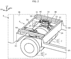
FIG. 2 ]
FIG. 2 is a perspective view of the periphery of a drive apparatus arranged on the front side of the electric truck ofFIG.1 . - [
FIG. 3 ]
FIG. 3 is a side view of a drive apparatus applied to an electric truck according to an embodiment, omitting one of the wheels. - [
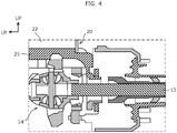
FIG. 4 ]
FIG. 4 is a cross-sectional view taken along the A-A arrows ofFIG. 3 . - [
FIG. 5 ]
FIG. 5 is a perspective view of a drive apparatus applied to an electric truck according to an embodiment, omitting a double-tire. - [
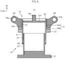
FIG. 6 ]
FIG. 6 is a schematic cross-sectional view explaining the main configuration of a drive apparatus. - [
FIG. 7 ]
FIG. 7 is a partial cross-sectional view of a drive apparatus applied to an electric truck as an embodiment, which is cut in a vehicle front-rear direction through a steering center. - [
FIG. 8 ]
FIG. 8 shows examples in which a common drive apparatus is applied to electric trucks having different specifications. - An electric truck according to an embodiment will now be described with reference to accompanying drawings. The following embodiment is merely example, so there is no intention to exclude various modifications and applications of techniques not explicitly described in the following embodiment. Each of the structures of the present embodiment can be variously modified without departing from the scope of the structure. The structures may be appropriately selected, omitted, or combined according to the requirement.
- As illustrated in
FIG. 1 , theelectric truck 1 is a vehicle that travels only by driving force of a motor 11 (seeFIG. 3 ) and that does not have an internal combustion engine but is equipped with a driving apparatus. InFIG. 1 , the electric truck 1 (hereinafter simply referred to as the "truck 1") including a pair of left and right side frames 1A (also referred to as chassis frames) extending in the front-rear direction of the vehicle and acab 1B disposed in the front part of the vehicle is illustrated, and the illustration of the body is omitted. In addition to the side frames 1A, a frame extending in the vehicle widthwise direction may be provided, or the side frames 1A may be omitted. - In the following description, the forward direction of the
truck 1 will be referred to as the "front", and the opposite direction to the front will be referred to as the "rear". In addition, the left-right direction is determined with reference to the state of thetruck 1 facing forward. The left-right direction is orthogonal to the front-rear direction of the vehicle. Hereinafter, the left-right direction is referred to as a "vehicle width direction", and the front-rear direction of the vehicle is simply referred to as a "front-rear direction". - As illustrated in
Fig. 1 andFig. 2 , thetruck 1 of the present embodiment includes double-tires 2 each consisting of twodriving wheels 2A. In thetruck 1 of the present embodiment, a pair of left and right double-tires 2 are provided on the front side (front wheel side) of the vehicle, and two pairs of left and right double-tires 2 are provided side by side on the rear side (rear wheel side) of the vehicle, but the number of double-tires 2 in the front-rear direction is not limited to this. Each double-tire 2 is provided with onedrive unit 10 including themotor 11, and the driving force of themotor 11 is transmitted to the double-tire 2 (driving wheels 2A). The configuration of thedrive unit 10 will be described below. - The
truck 1 includes a body frame casing 5 composed of a pair of mountingframe bodies 5A extending in the vehicle width direction, a pair ofcross members 5B and a pair ofcross members 5C connecting the mountingframe bodies 5A, and body-connectingparts drive unit 10 disposed in the frame of the body frame casing 5 to the respectivemounting frame bodies 5A. - The pair of mounting
frame bodies 5A are disposed apart from each other in the front-rear direction. Each of thecross members frame bodies 5A. The pair of left andright drive units 10 are disposed in the frame of the body frame casing 5 so as to be adjacent to each other in the vehicle width direction. In thetruck 1 of the present embodiment, onebody frame casing 5 is provided on the front side (front wheel side) of the vehicle, and twobody frame casings 5 are provided on the rear side (rear wheel side) of the vehicle, but the number ofbody frame casings 5 in front and that in rear are not limited to these. As described above, in thetruck 1 of the present embodiment, the body frame casing 5 in which the pair of left andright drive units 10 are connected by the body-connectingparts - The body frame casing 5 of the present embodiment is formed of a rectangular flat plate member in which the front and rear mounting
frame bodies 5A extend in the vehicle width direction and the vertical direction. Thecross members 5B located above thebody frame casing 5 are each formed of a member having a U-shaped or hat-shaped cross section extending in the front-rear direction, and connects the flanges at the upper ends of the front and rear mountingframe bodies 5A. On the other hand, thecross members 5C located on the sides of thebody frame casing 5 are each formed of a flat plate member extending in the front-rear direction and the vertical direction and having a concave portion formed so as to surround thedriving wheel 2A. Any one of thecross members - As illustrated in
Fig. 2 , the front body-connectingpart 32 connects the front side of thedrive unit 10 in the frame to the front mountingframe body 5A, and the rear body-connectingpart 33 connects the rear side of thedrive unit 10 in the frame to the rearmounting frame body 5A. As illustrated inFig. 3 andFig. 5 , the front and rear body-connectingparts parts frame body 5A to constitute a part of the frame of thetruck 1. - At the front end portion of the front body-connecting
part 32, a planar mountingface 32a extending in a direction orthogonal to the front-rear direction is provided. At the rear end portion of the front body-connectingpart 32, a pair of connectingside protruding portions 32b protruding rearward is provided. The mountingface 32a is a part to be attached to the mountingframe body 5A, and has a fastening hole (not shown). The pair of connectingside protruding portions 32b are separated from each other in the vehicle width direction, and haveholes 32c penetrating in the vehicle width direction. The connectingside protruding portion 32b constitutes a part of ahinge part 40, which will be described below, and is connected to asteering gear part 30, which will also be described below. - At the rear end portion of the rear body-connecting
part 33, a planar mountingface 33a extending in a direction orthogonal to the front-rear direction is provided. At the front end portion of the rear body-connectingpart 33, a pair of connectingside protruding portions 33b protruding forward and each having ahole 33c are provided. The configuration of the mountingface 33a and the connectingside protruding portions 33b are the same as the configuration of the mountingface 32a and the connectingside protruding portions 32b, respectively. - As illustrated in
Fig. 3 andFig. 4 , thedrive unit 10 includes themotor 11 that generates driving force, areducer 12 that reduces a rotation speed of themotor 11, afinal gear 14 that is connected to thereducer 12 and transfers the driving force of themotor 11 to adrive shaft 13 of the double-tire 2, and adrive unit housing 15 that integrally accommodates these units. That is, thedrive unit housing 15 integrally houses themotor 11, thereducer 12, and thefinal gear 14. - The
motor 11 functions as an electric motor when the vehicle is driven, and functions as an electric generator when the vehicle is decelerated. Thereducer 12 decelerates the rotation speed of themotor 11 to amplify the motor torque (driving force). Thedrive shaft 13 is extended in the vehicle width direction with thetruck 1 traveling straight forward, and is arranged in pairs on the left and right across thefinal gear 14. Thefinal gear 14 is positioned substantially at the center of the twodriving wheels 2A in the vehicle width direction, and distributes the driving force of themotor 11 amplified by thereducer 12 to the twodriving wheels 2A. Thefinal gear 14 may be included in a differential gear. However, in the double-tire 2, the differential gear can be omitted because the twodriving wheels 2A are closer to each other than the normal left and right wheels. - In addition to the
drive units 10 disposed on the left and right sides of thetruck 1, the drive apparatus of thetruck 1 includes asuspension part 20 provided above thefinal gear 14 in thedrive unit housing 15, and asteering gear part 30 provided above thesuspension part 20. Further, the drive apparatus of the present embodiment includes the pair ofhinge parts 40 provided one on each of the vehicle front side and the vehicle rear side of thesteering gear part 30, respectively, and the body-connectingparts - The
suspension part 20 functions as a suspension for absorbing vertical vibration of the double-tire 2. Thesteering gear part 30 is configured to be able to steer the double-tire 2, and has a function of steering the double-tire 2 around asteering shaft 30a (changing a steering angle). The double-tire 2 may be steered manually or automatically. Each double-tire 2 is individually driven and individually steered. Thehinge part 40 has a function of suppressing the vertical vibration of the double-tire 2 from being transmitted to the vehicle body. The body-connectingparts steering gear part 30 and the vehicle body of thetruck 1 through the pair ofhinge parts 40. A pair of the front and rear body-connectingparts shaft 30a. - In the present embodiment, as illustrated in
Fig. 2 , both thesuspension part 20 and thesteering gear part 30 are located above a space between the twodriving wheels 2A constituting the double-tire 2. Further, in the drive apparatus shown inFIG. 3 , themotor 11 is disposed in front of thefinal gear 14 and above thereducer 12, but the position of themotor 11 may be set according to the specification and the size of themotor 11, the space in which themotor 11 can be disposed, and the like. For example, themotor 11 may be disposed behind thefinal gear 14, or may be disposed obliquely above thefinal gear 14. Alternatively, the output shaft (not shown) of themotor 11 may be disposed in a downward extending posture. - First, the
suspension part 20 will be described in detail. As illustrated inFig. 5 andFig. 6 , thesuspension part 20 of the present embodiment is an air suspension including anouter tube 21 centered at thesteering shaft 30a of the double-tire 2, and aninner tube 22 being concentric with theouter tube 21. Theinner tube 22 is slidable along an inner circumference face of theouter tube 21 in an axis direction and incapable of relatively rotating with respect to theouter tube 21. The steeringshaft 30a is a shaft portion having a steering center Cs when the double-tire 2 is steered, and extends in the vertical direction. The steering center Cs coincides with the centers of theouter tube 21 and theinner tube 22. - As illustrated in
Fig. 7 , thesuspension part 20 may also have acoil spring 28 surrounding theouter tube 21 and theinner tube 22. Thesuspension part 20 having thecoil spring 28 is applied to the relativelylightweight truck 1. On the other hand, thesuspension part 20 without thecoil spring 28 shown inFig. 5 andFig. 6 is applied to thetruck 1 which has a relatively large weight because thesuspension part 20 has a larger capacity of air than that of thesuspension part 20 having thecoil spring 28. Thesuspension part 20 shown inFig. 7 is basically the same as thesuspension part 20 shown inFig. 5 andFig. 6 except that thecoil spring 28 is provided. Therefore, hereinafter,Fig. 7 will be described with reference to one of the embodiments. - As illustrated in
Fig. 5 to Fig. 7 , each of theouter tube 21 and theinner tube 22 has a vertically-long cylindrical shape, and the inner diameter of theouter tube 21 is slightly larger than the outer diameter of theinner tube 22. The upper opening of theouter tube 21 is sealed by acover part 30b to which thesteering shaft 30a is fixed, and the lower opening of theouter tube 21 communicates with theinner tube 22 by insertion of the upper portion of theinner tube 22. The upper opening of theinner tube 22 enters the lower portion of theouter tube 21 and communicates with theouter tube 21, the lower opening of theinner tube 22 is sealed with aflat drive head 25. Air is sealed inside theouter tube 21 and theinner tube 22. - As illustrated in
Fig. 6 , thedrive head 25 may have a stepped shape so that thedrive head 25 is also fixed to the inner peripheral surface at the lower end of theinner tube 22. In this case, the fixation between theinner tube 22 and thedrive head 25 becomes strong, and it becomes possible to resist a load in the lateral direction. Astopper 24 that prevents theinner tube 22 from coming off and that seals the lower end of theouter tube 21 is fixed to the lower end of theouter tube 21. When thecoil spring 28 is provided on thesuspension part 20, thecoil spring 28 is arranged around theouter tube 21 and theinner tube 22, as illustrated inFig. 7 . - The
outer tube 21 and theinner tube 22 are relatively displaced (slide) in the axial direction (vertical direction) according to the vertical vibration of the truck 1 (vertical movement of the double-tire 2). As illustrated inFig. 6 , thesuspension part 20 of the present embodiment includes a lowfrictional member 23 being arranged at a point where theouter tube 21 is brought into slidable contact with theinner tube 22. The lowfrictional member 23 is a member that reduces sliding friction of theouter tube 21 withinner tube 22, and is attached to, for example, the inner peripheral surface of theouter tube 21 or the outer peripheral surface of theinner tube 22. The lowfrictional member 23 avoids direct contact between theouter tube 21 and theinner tube 22, and reduces the friction when these slide relatively in the vertical direction. - As illustrated in
Fig. 5 andFig. 7 , in the present embodiment, an annular attachingpart 26 is fixed to the outer peripheral surface of the upper portion of theouter tube 21, and the attachingpart 26 and thedrive head 25 are linked by a stabilizer 27 (also referred to as a steering arm). Thereby, the relative rotation of theouter tube 21 and theinner tube 22 is restricted. Further, by linking the upper part of theouter tube 21 and the lower part of theinner tube 22 to each other, relative vertical movement of theouter tube 21 and theinner tube 22 is allowed, and these movements are smoothed. - In the
suspension part 20 of the present embodiment,shock absorbers 29 are provided on both left and right sides of thestabilizer 27, respectively. Theshock absorber 29 has an upper end connected to the attachingpart 26 and a lower end connected to thedrive head 25 via mounting components. - Next, the
steering gear part 30 will be described in detail. Thesteering gear part 30 of the present embodiment is configured to be capable of steering the double-tire 2 up to 90° leftward and rightward on an assumption that a steering angle of the double-tire 2 under a state where thetruck 1 is traveling straight forward (that is, when thedrive shaft 13 extends in the vehicle width direction) is 0° (reference). That is, the double-tire 2 can be steered by 180° by thesteering gear part 30, and when the double-tire 2 is steered 90° leftward or rightward from the forward direction, the extending direction of thedrive shaft 13 becomes the front-rear direction, and thetruck 1 can move in the left-right direction. - As illustrated in
Fig. 5 andFig. 7 , thesteering gear part 30 includes thesteering shaft 30a fixed to thecover part 30b, aspur gear 30c fixed to thesteering shaft 30a, anannular gear 30d that meshes with thespur gear 30c, atube portion 30e concentrically arranged with thesteering shaft 30a, and a drivingpart 31 connected to theannular gear 30d to rotate theannular gear 30d. The drivingpart 31 is an actuator such as a hydraulic cylinder or a stepping motor. - In the example of
Fig. 5 , when the drivingpart 31 rotates theannular gear 30d clockwise in a top view, thespur gear 30c also rotates clockwise. Accordingly, since thesteering shaft 30a also rotates clockwise, the double-tire 2 is steered rightward. Conversely, when the drivingpart 31 rotates theannular gear 30d counterclockwise, thespur gear 30c also rotates counterclockwise. Accordingly, since thesteering shaft 30a also rotates counterclockwise, the double-tire 2 is steered leftward. As illustrated inFig. 3 , the steeringshaft 30a is disposed equidistant from each of the pair of mountingframes 5A. - As illustrated in
Fig. 5 to Fig. 7 , a pair of front and rear protrudingportions 30f are formed on thetube portion 30e and connected to the connectingside protruding portions parts portion 30f protrudes in the front-rear direction from each of the outer peripheral surface on the front side and the outer peripheral surface on the rear side of thetube portion 30e, and forms thehinge part 40 together with the above-mentioned connectingside protruding portions front protruding portion 30f is interposed between the pair of connectingside protruding portions 32b, and a portion functioning as a rotating center Ch of thehinge parts 40 is inserted into thehole 32c of each connectingside protruding portion 32b. In the protrudingportions 30f of the present embodiment, a cylindrical portion (not shown) having a throughhole 30g penetrating in the vehicle width direction is inserted into thehole 32c. - Similarly, the
rear protruding portion 30f is interposed between the pair of connectingside protruding portions 33b, and a cylindrical portion functioning as the rotating center Ch of thehinge part 40 is inserted into thehole 33c of each connectingside protruding portion 33b. A bush (not shown) that absorbs a load to be transmitted to the vehicle body is interposed in thehinge parts 40 of the present embodiment. With the bush interposed, the load to be transmitted to the vehicle body is absorbed, and the drive feel is further improved. - As illustrated in
Fig. 6 andFig. 7 , in thetube portion 30e, thecover part 30b and the upper portion of theouter tube 21 are concentrically arranged and rotatably supported with respect to thetube portion 30e. That is, theouter tube 21, theinner tube 22, thecover part 30b, and thedrive head 25 rotate integrally about thesteering shaft 30a with respect to thetube portion 30e. Athrust plate 34 that receives a vertical load is interposed between the inner peripheral surface of thetube portion 30e and the outer peripheral surface of theouter tube 21. At the upper end of thethrust plate 34, astopper 36 for preventing theouter tube 21 from coming off is fixed. - The
thrust plate 34 of the present embodiment includes acylinder portion 34a located between thetube portion 30e and theouter tube 21, and aflange portion 34b projecting radially outward from a lower end of thecylinder portion 34a. Theflange portion 34b is sandwiched between the upper surface of the attachingpart 26 and the lower surface of thetube portion 30e. Thethrust plate 34 is a metal component that is not fixed to any component and functions as a spacer, and avoids direct contact between thetube portion 30e on the fixed side and theouter tube 21 and the attachingpart 26 on the rotating side. Thethrust plate 34 is made replaceable due to wear. - The
steering gear part 30 of the present embodiment includes a lowfrictional member 35 arranged at a sliding position between theouter tube 21 and thethrust plate 34. The lowfrictional member 35 is a member that reduces friction between theouter tube 21 and thethrust plate 34, and is attached to, for example, the outer peripheral surface of theouter tube 21 or the inner peripheral surface of thethrust plate 34. The friction at the time of relative displacement between theouter tube 21 and thethrust plate 34 is reduced by the lowfrictional member 35. - According to the
above truck 1, it is possible to obtain the following actions and effects. - (1) The drive apparatus is packaged by arranging the pair of
drive units 10 to be adjacent to each other in the frame of thebody frame casing 5 and connecting thedrive units 10 to the body frame casing 5 via the body-connectingparts Fig. 8 , a common drive apparatus can be applied to theelectric trucks 1' and 1" having different gross vehicle weight, cargo type, wheelbase, and the like. In other words, since it is not necessary to manufacture a drive apparatus for each of electric trucks having different specifications, manufacturing costs can be reduced. Further, the adjustment of the wheelbase can be made on the customer side, and the commercial value can be enhanced. The electric truck 1' inFig. 8 is one having a single-axle on the front wheel side and a single-axle also on the rear wheel side, and theelectric truck 1" inFig. 8 is a single-axle truck on the front wheel side and a dual-axle truck on the rear wheel side. By using the above-described drive apparatus, an appropriate number of axels can be arranged on the front wheel side and the rear wheel side. - (2) In the above-described
truck 1, thedrive unit 10 including thedrive unit housing 15 integrally accommodating themotor 11, thereducer 12, and thefinal gear 14 is provided to each of thedriving wheels 2A arranged on each of the left and right sides of thetruck 1. Thedrive unit 10 in which thereducer 12 is included can obtain large driving force. Further, integrally accommodating themotor 11 and other elements in thedrive unit housing 15 makes thedrive unit 10 possible to have a compact size. - (3) According to the above-described
truck 1, providing theair suspension part 20 above thefinal gear 14 in thedrive unit housing 15 makes it possible to absorb vehicle-body vibration with a compact structure. - (4) In the above-described
truck 1, the steeringshaft 30a is disposed equidistant from each of the pair of mountingframes 5A. That is, the double-tire 2 is steered at the center in the front-rear direction within the frame of thebody frame casing 5, so that the arrangement balance can be improved. - (5) According to the
truck 1 described above, since thesteering gear part 30 is configured to be capable of steering thedriving wheel 2A up to 90° leftward and rightward from reference (that is, up to 180°), the steering performance can be enhanced and mobile parking in the left-right direction is also possible, for example. - (6) In the above-described
truck 1, thesteering gear part 30 is coupled to the mountingframe body 5A via the pair of thehinge parts 40 and the pair of the body-connectingparts hinge parts 40, which have a function to suppress propagation of vertical vibration of thedriving wheel 2A to the vehicle body, can suppress the vehicle vibration as well as thesuspension part 20, so that drive feeling can be improved. - (7) Assuming that the
electric truck 1 includes the double-tires 2 and thedrive unit 10 transmits driving force to the double-tire 2, the drive apparatus can be adopted to an electric truck larger in size. - (8) In the drive apparatus of the present embodiment, the
drive unit 10 including adrive unit housing 15 integrally accommodating themotor 11, thereducer 12, and thefinal gear 14 is provided for each double-tire 2 disposed on each of the left and right sides of thetruck 1, and thesuspension part 20 and thesteering gear part 30 are provided above thefinal gear 14. This drive apparatus drives each individual double-tire 2 and steers each individual double-tire 2, and consequently can achieve a steering angle in the range of 0° to 180°, which makes the turning radius small. Consequently, a drive apparatus forelectric truck 1 which has steering performance of 0° to 180° can be provided while adopting a double-tire structure. - (9) In particular, according to the drive apparatus of the present embodiment, since the
suspension part 20 and thesteering gear part 30 are disposed over a space between two drivingwheels 2A constituting the double-tire 2, the weight balance is good, so that the steering performance of the double-tire 2 can be enhanced. - (10) In the drive apparatus described above, the
suspension part 20 is an air suspension including: theouter tube 21 centered at thesteering shaft 30a of thedouble tire 2; and theinner tube 22 being slidable along the inner circumference face of theouter tube 21 in the axis direction and being incapable of relatively rotating with respect to theouter tube 21. As such, the air suspension serving as thesuspension part 20 can have a simpler configuration as compared with a hydraulic suspension and an electromagnetic suspension. - (11) As illustrated in
Fig. 7 , since thesuspension part 20 also has thecoil spring 28, it is possible to configure thesuspension part 20 appropriate for the gross vehicle weight. - (12) The
suspension part 20 of the present embodiment includes a lowfrictional member 23 disposed at a sliding position between theouter tube 21 and theinner tube 22. For this reason, the friction when theouter tube 21 and theinner tube 22 relatively slide can be reduced, and the performance of the air suspension can be improved. - (13) According to the drive apparatus described above, since the upper part of the
outer tube 21 and the lower part of theinner tube 22 are linked to each other, relative vertical movement can be allowed under a state where the relative rotation of theouter tube 21 and theinner tube 22 is restricted. Further, the axial movement of theouter tube 21 and theinner tube 22 can be smoothed. - (14) In the drive apparatus of the present embodiment, since the
thrust plate 34 interposed between thetube portion 30e and theouter tube 21 functions as a spacer, direct contact between thetube portion 30e on the fixed side and theouter tube 21 and the attachingpart 26 on the rotating side can be avoided. Further, since thethrust plate 34 receives a load in the vertical direction, the drive feel can be further improved. - (15) In particular, since the
steering gear part 30 of the present embodiment includes a lowfrictional member 35 disposed at a sliding position between theouter tube 21 and thethrust plate 34, friction at the time of relative displacement between theouter tube 21 and thethrust plate 34 can be reduced. Therefore, the steering performance can be further improved. - The above-described drive apparatus and the
truck 1 are all examples. For example, although thesuspension part 20 is an air suspension including theouter tube 21 and theinner tube 22, or a hybrid of an air suspension and thecoil spring 28, the suspension part can be selected based on the load and application. Alternatively, a hydraulic suspension or an electromagnetic suspension may be employed. - The low
frictional members thrust plate 34 are not essential and can be omitted. The structure for restricting the relative rotation between theouter tube 21 and theinner tube 22 is not limited to the link connection by thestabilizer 27. Thesteering gear part 30 may be realized using gears other than thespur gear 30c and theannular gear 30d. The range of the steering angle of the double-tire 2 may be set according to the required turning radius. - In the above-described
truck 1, although the drive apparatus is packaged by arranging the pair ofdrive units 10 adjacent to each other in the vehicle width direction in the frame of thebody frame casing 5, a drive unit except for the above-describeddrive unit 10 may be arranged in thebody frame casing 5. For example, thedrive unit housing 15 does not have to accommodate thereducer 12, and the arrangement of thesuspension part 20 and thesteering gear part 30 may be different from the above-described arrangement. Note that thehinge parts 40 are not essential and may be omitted. The above-describedtruck 1 has double-tires 2, but may alternatively have a single-tire structure. In this alternative, a drive unit may be arranged at each driving wheels, considering weight balance. -
- 1, 1', 1": truck (electric truck)
- 2: double-tire
- 2A: driving wheel
- 5: body frame casing
- 5A: mounting frame body
- 5B, 5C: cross member
- 10: drive unit
- 11: motor
- 12: reducer
- 14: final gear
- 15: drive unit housing
- 20: suspension part
- 21: outer tube
- 22: inner tube
- 30: steering gear part
- 30a: steering shaft
- 32: front body-connecting part
- 33: rear body-connecting part
- Cs: steering center
Claims (7)
- An electric truck comprising:drive units being provided to each of driving wheels on left and right sides of the electric truck, each of the drive units transmitting a driving force of a motor to each of the driving wheels;a body frame casing comprising a pair of mounting frame bodies extending in a vehicle width direction of the electric truck and being arranged apart in a vehicle front-rear direction and a pair of cross members connecting the pair of mounting frame bodies; andbody-connecting parts connecting each of a vehicle front side and a vehicle rear side of each of the drive units arranged in a frame of the body frame casing to each of the mounting frame bodies, whereinthe pair of drive units are arranged so as to be adjacent to each other in the vehicle width direction inside the frame of the body frame casing.
- The electric truck according to claim 1, wherein each of the drive units comprises the motor, a reducer that reduces a rotation speed of the motor, a final gear that is coupled to the reducer and that transfers the driving force of the motor to the driving wheel, and a drive unit housing that integrally accommodates the motor, the reducer, and the final gear.
- The electric truck according to claim 2, further comprising an air suspension part disposed over the final gear in the drive unit housing.
- The electric truck according to any one of claims 1-3, further comprising a steering gear part provided on the driving wheel and configured to be able to steer the driving wheel, wherein
a steering shaft having a steering center of the driving wheel is disposed equidistantly from each of the pair of mounting frame bodies. - The electric truck according to claim 4, wherein the steering gear part is configured to be capable of steering the driving wheel up to 90° leftward and rightward on an assumption that a steering angle of the driving wheel under a state where the electric truck is traveling straight forward is 0°.
- The electric truck according to any one of claims 3-5, further comprising a pair of hinge parts disposed one to each of a vehicle front side and a vehicle rear side of the steering gear part, wherein
the pair of body-connecting parts connect the steering gear part to the mounting frame body through the pair of hinge parts. - The electric truck according to any one of claims 1-6, wherein:the electric truck is provided with double-tires constituting two of the driving wheels; andthe drive units transfer the driving force to the double-tires.
Applications Claiming Priority (2)
| Application Number | Priority Date | Filing Date | Title |
|---|---|---|---|
| JP2020010656A JP7422551B2 (en) | 2020-01-27 | 2020-01-27 | electric truck |
| PCT/JP2020/045615 WO2021153015A1 (en) | 2020-01-27 | 2020-12-08 | Electric truck |
Publications (2)
| Publication Number | Publication Date |
|---|---|
| EP4094966A1 true EP4094966A1 (en) | 2022-11-30 |
| EP4094966A4 EP4094966A4 (en) | 2023-10-04 |
Family
ID=77078213
Family Applications (1)
| Application Number | Title | Priority Date | Filing Date |
|---|---|---|---|
| EP20917253.5A Pending EP4094966A4 (en) | 2020-01-27 | 2020-12-08 | Electric truck |
Country Status (5)
| Country | Link |
|---|---|
| US (1) | US20220410692A1 (en) |
| EP (1) | EP4094966A4 (en) |
| JP (1) | JP7422551B2 (en) |
| CN (1) | CN115038603A (en) |
| WO (1) | WO2021153015A1 (en) |
Family Cites Families (11)
| Publication number | Priority date | Publication date | Assignee | Title |
|---|---|---|---|---|
| JP3961719B2 (en) * | 1999-06-18 | 2007-08-22 | 三菱ふそうトラック・バス株式会社 | Axle structure of electric vehicle |
| AU3101901A (en) * | 2000-01-20 | 2001-07-31 | Kress Corporation | Off-highway off-road dump truck |
| JP2007022163A (en) * | 2005-07-12 | 2007-02-01 | Nissan Motor Co Ltd | Loading structure of running gear |
| JP2007022276A (en) * | 2005-07-15 | 2007-02-01 | Nissan Motor Co Ltd | Motor mount of electric vehicle |
| EP2360047B1 (en) * | 2010-02-15 | 2012-07-25 | Hitachi Construction Machinery Co., Ltd. | Vehicle drive unit for dump truck |
| DE102010017991A1 (en) * | 2010-04-21 | 2011-10-27 | Fachhochschule Südwestfalen | Autonomous axle module for motor vehicle, has electric drive wheel suspension unit for driving left or right wheel, where axle module is operated separately in permanently functional manner |
| JP2014101043A (en) * | 2012-11-20 | 2014-06-05 | Toshiba Corp | Drive device and vehicle |
| GB2521647A (en) * | 2013-12-24 | 2015-07-01 | Mira Ltd | An axle assembly, a steering mechanism, a vehicle, and a trailer |
| US11292332B2 (en) * | 2017-07-12 | 2022-04-05 | Allison Transmission, Inc. | Axle assembly for low floor vehicle |
| JP6703965B2 (en) * | 2017-07-28 | 2020-06-03 | ダイムラー・アクチェンゲゼルシャフトDaimler AG | Electric truck drive |
| DE102018208975A1 (en) * | 2018-06-07 | 2019-12-12 | Zf Friedrichshafen Ag | Industrial truck with a vehicle frame and with a travel drive |
-
2020
- 2020-01-27 JP JP2020010656A patent/JP7422551B2/en active Active
- 2020-12-08 EP EP20917253.5A patent/EP4094966A4/en active Pending
- 2020-12-08 US US17/782,484 patent/US20220410692A1/en active Pending
- 2020-12-08 CN CN202080094675.0A patent/CN115038603A/en active Pending
- 2020-12-08 WO PCT/JP2020/045615 patent/WO2021153015A1/en unknown
Also Published As
| Publication number | Publication date |
|---|---|
| CN115038603A (en) | 2022-09-09 |
| JP2021115963A (en) | 2021-08-10 |
| WO2021153015A1 (en) | 2021-08-05 |
| JP7422551B2 (en) | 2024-01-26 |
| US20220410692A1 (en) | 2022-12-29 |
| EP4094966A4 (en) | 2023-10-04 |
Similar Documents
| Publication | Publication Date | Title |
|---|---|---|
| EP3241691B1 (en) | Suspension module having a subframe assembly | |
| US9266557B2 (en) | Steering device for wheel | |
| EP1950072B1 (en) | Arrangement of in-wheel motor and suspension links for vehicle | |
| US3703215A (en) | Independent front suspension system for a front wheel drive automobile | |
| US4848789A (en) | Vehicle chassis tranverse structural member | |
| US9346492B2 (en) | Off-road vehicle | |
| KR20110086005A (en) | A vehicle suspension | |
| US20140265201A1 (en) | Automotive rear suspension subassembly | |
| CN109789748B (en) | Suspension structure for in-wheel motor drive device | |
| WO2022134087A1 (en) | Suspension structure, angle module system and motor vehicle | |
| JP2008168804A (en) | Arrangement structure of driving device for vehicle | |
| US20190184822A1 (en) | Drive Configuration for Vehicle | |
| EP4094965A1 (en) | Drive device for electric truck | |
| EP4094964A1 (en) | Drive device for electric truck | |
| CN110997356B (en) | Axle with centrally arranged drive unit | |
| EP4094966A1 (en) | Electric truck | |
| RU2565631C2 (en) | Automotive steering control system | |
| JP4857658B2 (en) | Suspension device | |
| JP2005343354A (en) | Motor driving system of automobile | |
| US11376910B1 (en) | Suspension structure of utility vehicle | |
| RU2740522C1 (en) | Controlled suspension of two-wheel unit | |
| RU2743346C1 (en) | Wheel unit with controlled suspension | |
| WO2023048257A1 (en) | Vehicle | |
| JP2022054931A (en) | Suspension structure for in-wheel motor drive device | |
| JP2022114514A (en) | vehicle suspension system |
Legal Events
| Date | Code | Title | Description |
|---|---|---|---|
| STAA | Information on the status of an ep patent application or granted ep patent |
Free format text: STATUS: THE INTERNATIONAL PUBLICATION HAS BEEN MADE |
|
| PUAI | Public reference made under article 153(3) epc to a published international application that has entered the european phase |
Free format text: ORIGINAL CODE: 0009012 |
|
| STAA | Information on the status of an ep patent application or granted ep patent |
Free format text: STATUS: REQUEST FOR EXAMINATION WAS MADE |
|
| 17P | Request for examination filed |
Effective date: 20220825 |
|
| AK | Designated contracting states |
Kind code of ref document: A1 Designated state(s): AL AT BE BG CH CY CZ DE DK EE ES FI FR GB GR HR HU IE IS IT LI LT LU LV MC MK MT NL NO PL PT RO RS SE SI SK SM TR |
|
| RAP1 | Party data changed (applicant data changed or rights of an application transferred) |
Owner name: DAIMLER TRUCK AG |
|
| DAV | Request for validation of the european patent (deleted) | ||
| DAX | Request for extension of the european patent (deleted) | ||
| A4 | Supplementary search report drawn up and despatched |
Effective date: 20230904 |
|
| RIC1 | Information provided on ipc code assigned before grant |
Ipc: B60K 1/02 20060101ALI20230829BHEP Ipc: B60G 11/58 20060101ALI20230829BHEP Ipc: B62D 21/00 20060101ALI20230829BHEP Ipc: B60K 7/00 20060101AFI20230829BHEP |