EP4094956A1 - Non-pneumatic tire and rim assembly - Google Patents
Non-pneumatic tire and rim assembly Download PDFInfo
- Publication number
- EP4094956A1 EP4094956A1 EP22174604.3A EP22174604A EP4094956A1 EP 4094956 A1 EP4094956 A1 EP 4094956A1 EP 22174604 A EP22174604 A EP 22174604A EP 4094956 A1 EP4094956 A1 EP 4094956A1
- Authority
- EP
- European Patent Office
- Prior art keywords
- pneumatic tire
- spoke
- ring
- rim
- wheel assembly
- Prior art date
- Legal status (The legal status is an assumption and is not a legal conclusion. Google has not performed a legal analysis and makes no representation as to the accuracy of the status listed.)
- Granted
Links
- 230000014759 maintenance of location Effects 0.000 claims abstract description 6
- 238000010146 3D printing Methods 0.000 claims abstract description 4
- 230000000295 complement effect Effects 0.000 claims abstract description 4
- 238000004519 manufacturing process Methods 0.000 claims description 2
- 239000002861 polymer material Substances 0.000 claims 1
- 239000000463 material Substances 0.000 description 7
- 229920001971 elastomer Polymers 0.000 description 4
- 230000000712 assembly Effects 0.000 description 3
- 238000000429 assembly Methods 0.000 description 3
- 238000001746 injection moulding Methods 0.000 description 3
- 239000005060 rubber Substances 0.000 description 3
- 230000002787 reinforcement Effects 0.000 description 2
- 239000000243 solution Substances 0.000 description 2
- 229920002943 EPDM rubber Polymers 0.000 description 1
- 244000043261 Hevea brasiliensis Species 0.000 description 1
- 229910000831 Steel Inorganic materials 0.000 description 1
- 239000002998 adhesive polymer Substances 0.000 description 1
- 238000000748 compression moulding Methods 0.000 description 1
- 230000001419 dependent effect Effects 0.000 description 1
- 239000013013 elastic material Substances 0.000 description 1
- 239000000806 elastomer Substances 0.000 description 1
- 239000013536 elastomeric material Substances 0.000 description 1
- 239000004744 fabric Substances 0.000 description 1
- 239000012530 fluid Substances 0.000 description 1
- 238000002347 injection Methods 0.000 description 1
- 239000007924 injection Substances 0.000 description 1
- 238000012423 maintenance Methods 0.000 description 1
- 238000000034 method Methods 0.000 description 1
- 239000000203 mixture Substances 0.000 description 1
- 238000012544 monitoring process Methods 0.000 description 1
- 229920003052 natural elastomer Polymers 0.000 description 1
- 229920001194 natural rubber Polymers 0.000 description 1
- 229920002857 polybutadiene Polymers 0.000 description 1
- 229920000642 polymer Polymers 0.000 description 1
- 229920002635 polyurethane Polymers 0.000 description 1
- 239000004814 polyurethane Substances 0.000 description 1
- 239000007787 solid Substances 0.000 description 1
- 239000010959 steel Substances 0.000 description 1
- 229920003048 styrene butadiene rubber Polymers 0.000 description 1
- 229920002725 thermoplastic elastomer Polymers 0.000 description 1
Images


Classifications
-
- B—PERFORMING OPERATIONS; TRANSPORTING
- B60—VEHICLES IN GENERAL
- B60C—VEHICLE TYRES; TYRE INFLATION; TYRE CHANGING; CONNECTING VALVES TO INFLATABLE ELASTIC BODIES IN GENERAL; DEVICES OR ARRANGEMENTS RELATED TO TYRES
- B60C7/00—Non-inflatable or solid tyres
- B60C7/24—Non-inflatable or solid tyres characterised by means for securing tyres on rim or wheel body
-
- B—PERFORMING OPERATIONS; TRANSPORTING
- B60—VEHICLES IN GENERAL
- B60C—VEHICLE TYRES; TYRE INFLATION; TYRE CHANGING; CONNECTING VALVES TO INFLATABLE ELASTIC BODIES IN GENERAL; DEVICES OR ARRANGEMENTS RELATED TO TYRES
- B60C7/00—Non-inflatable or solid tyres
- B60C7/10—Non-inflatable or solid tyres characterised by means for increasing resiliency
- B60C7/14—Non-inflatable or solid tyres characterised by means for increasing resiliency using springs
- B60C7/146—Non-inflatable or solid tyres characterised by means for increasing resiliency using springs extending substantially radially, e.g. like spokes
-
- B—PERFORMING OPERATIONS; TRANSPORTING
- B29—WORKING OF PLASTICS; WORKING OF SUBSTANCES IN A PLASTIC STATE IN GENERAL
- B29D—PRODUCING PARTICULAR ARTICLES FROM PLASTICS OR FROM SUBSTANCES IN A PLASTIC STATE
- B29D30/00—Producing pneumatic or solid tyres or parts thereof
- B29D30/02—Solid tyres ; Moulds therefor
-
- B—PERFORMING OPERATIONS; TRANSPORTING
- B33—ADDITIVE MANUFACTURING TECHNOLOGY
- B33Y—ADDITIVE MANUFACTURING, i.e. MANUFACTURING OF THREE-DIMENSIONAL [3-D] OBJECTS BY ADDITIVE DEPOSITION, ADDITIVE AGGLOMERATION OR ADDITIVE LAYERING, e.g. BY 3-D PRINTING, STEREOLITHOGRAPHY OR SELECTIVE LASER SINTERING
- B33Y80/00—Products made by additive manufacturing
-
- B—PERFORMING OPERATIONS; TRANSPORTING
- B60—VEHICLES IN GENERAL
- B60B—VEHICLE WHEELS; CASTORS; AXLES FOR WHEELS OR CASTORS; INCREASING WHEEL ADHESION
- B60B25/00—Rims built-up of several main parts ; Locking means for the rim parts
- B60B25/002—Rims split in circumferential direction
- B60B25/006—Rims split symmetrically
-
- B—PERFORMING OPERATIONS; TRANSPORTING
- B60—VEHICLES IN GENERAL
- B60C—VEHICLE TYRES; TYRE INFLATION; TYRE CHANGING; CONNECTING VALVES TO INFLATABLE ELASTIC BODIES IN GENERAL; DEVICES OR ARRANGEMENTS RELATED TO TYRES
- B60C7/00—Non-inflatable or solid tyres
- B60C7/10—Non-inflatable or solid tyres characterised by means for increasing resiliency
- B60C7/14—Non-inflatable or solid tyres characterised by means for increasing resiliency using springs
- B60C7/143—Non-inflatable or solid tyres characterised by means for increasing resiliency using springs having a lateral extension disposed in a plane parallel to the wheel axis
-
- B—PERFORMING OPERATIONS; TRANSPORTING
- B60—VEHICLES IN GENERAL
- B60C—VEHICLE TYRES; TYRE INFLATION; TYRE CHANGING; CONNECTING VALVES TO INFLATABLE ELASTIC BODIES IN GENERAL; DEVICES OR ARRANGEMENTS RELATED TO TYRES
- B60C7/00—Non-inflatable or solid tyres
- B60C7/22—Non-inflatable or solid tyres having inlays other than for increasing resiliency, e.g. for armouring
-
- B—PERFORMING OPERATIONS; TRANSPORTING
- B60—VEHICLES IN GENERAL
- B60C—VEHICLE TYRES; TYRE INFLATION; TYRE CHANGING; CONNECTING VALVES TO INFLATABLE ELASTIC BODIES IN GENERAL; DEVICES OR ARRANGEMENTS RELATED TO TYRES
- B60C7/00—Non-inflatable or solid tyres
- B60C2007/005—Non-inflatable or solid tyres made by casting, e.g. of polyurethane
Definitions
- the invention relates in general to a vehicle wheel, and more particularly to a non-pneumatic tire and rim assembly and to its method of manufacturing.
- the pneumatic tire has been the solution of choice for vehicular mobility for over a century.
- the pneumatic tire is a tensile structure.
- the pneumatic tire has at least four characteristics that make the pneumatic tire so dominate today.
- Pneumatic tires are efficient at carrying loads, because all of the tire structure is involved in carrying the load.
- Pneumatic tires are also desirable because they have low contact pressure, resulting in lower wear on roads due to the distribution of the load of the vehicle.
- Pneumatic tires also have low stiffness, which ensures a comfortable ride in a vehicle.
- the primary drawback to a pneumatic tire is that it requires compressed fluid.
- a conventional pneumatic tire is rendered useless after a complete loss of inflation pressure.
- a tire designed to operate without inflation pressure may eliminate many of the problems and compromises associated with a pneumatic tire. Neither pressure maintenance nor pressure monitoring is required. Structurally supported tires such as solid tires or other elastomeric structures to date have not provided the levels of performance required from a conventional pneumatic tire. A structurally supported tire solution that delivers pneumatic tire-like performance would be a desirous improvement.
- Non-pneumatic tires are typically defined by their load carrying efficiency.
- Bottom loaders are essentially rigid structures that carry a majority of the load in the portion of the structure below the hub.
- Top loaders are designed so that all of the structure is involved in carrying the load. Top loaders thus have a higher load carrying efficiency than bottom loaders, allowing a design that has less mass.
- an improved non-pneumatic tire that has all the features of the pneumatic tires without the drawback of the need for air inflation is desired. It is also desired to have an improved non-pneumatic tire that has longer tread life as compared to a pneumatic tire of the same size.
- the invention relates to a non-pneumatic tire and wheel assembly in accordance with claim 1 and to a method in accordance with claim 10.
- the invention provides in a first aspect a non-pneumatic tire and wheel assembly comprising: a rim, a spoke ring structure having an inner ring that is mounted on an outer surface of the rim, wherein the inner ring has one or more retention nubs aligned for reception in complementary shaped grooves on the outer surface of the rim, wherein the spoke ring structure has a plurality of spoke members, and an outer tread ring mounted on the outer circumference of the spoke ring.
- Axial and “axially” means the lines or directions that are parallel to the axis of rotation of the tire.
- “Circumferential” means lines or directions extending along the perimeter of the surface of the annular tread perpendicular to the axial direction.
- Ring and radially mean directions radially toward or away from the axis of rotation of the tire.
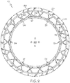
- the non-pneumatic tire and rim assembly 10 includes an outer annular tread ring 30, a spoke ring structure 20, and a rim 40.
- the outer annular tread ring 30 is preferably a one piece annular structure that is formed of a polymer, rubber or other desired elastomer.
- the tread ring 30 may be molded and cured as a one piece ring, and is mounted on the outer periphery of the spoke ring.
- the outer surface of the tread ring 30 may include tread elements such as ribs, blocks, lugs, grooves, and sipes as desired in order to improve the performance of the tire in various conditions.
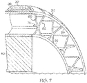
- the tread ring 30 may include an optional shear ring 35, as shown in FIG. 7 .
- the optional shear ring 35 is preferably a discrete ring, formed of a different material than the tread ring 30.
- the optional shear ring 35 may be integrally formed with the spoke ring 20, and located on the outer annular surface of the spoke ring.
- the optional shear ring 35 is preferably located between the outer circumference of the spoke ring, and the inner circumference of the tread ring.
- the optional shear ring 35 may optionally include one or more annular reinforcement layers, which could be fabric with optional parallel reinforcement cables preferably oriented in the zero degree (circumferential) orientation.
- the tread ring 30, optional shear ring 35 and spoke structure may be integrally formed via injection molding or three dimensional printing, or they may be formed in discrete components by injection molding or three dimensional printing and then assembled together.
- the non-pneumatic tire and rim assembly 10 further includes a spoke ring structure 20.
- the spoke ring structure 20 has an inner ring 22 that is mounted on the rim.
- the inner ring 22 has a plurality of retaining nubs or projections 24, as shown in FIG. 2 and FIG. 10 .
- the nubs 24 are hemispherical or rounded in cross-sectional shape.
- the nubs 24 may be any desired shape.
- the retaining nubs 24 are received in complementary shaped grooves 42 located on the outer surface 44 of the rim 40.
- the spoke ring structure further includes an outer ring 26 having an outer surface that is joined to the inner tread surface 32 by an adhesive polymer.
- the spoke ring structure further includes a plurality of spoke members that extend between the inner ring 22 to the outer ring 26.
- the spoke ring structure has a first spoke member 60 that extends from the inner ring 22 to the outer ring 26 at an angle.
- the spoke ring structure includes a second spoke member 62 that also extends from the inner ring to the outer ring 26 at an angle.
- the first and second spoke member 60, 62 are joined together at a junction 70 to form an X shaped spoke.
- the first and second spoke members 60, 62 may be straight or curved.
- the spoke ring structure 20 is preferably an integrally formed annular structure made of a resilient elastomeric material or moldable polymeric material such as natural rubber, styrene butadiene rubber, polybutadiene rubber or EPDM rubber or a blend of two or more of these rubbers which can be utilized in either injection molding or compression molding.
- the spoke ring structure 20 has an axial thickness equal to the axial thickness of the non-pneumatic tire.
- the spoke ring structure 20 has a plurality of spokes that connect an inner ring 22 and an outer ring 24.
- the spoke disks are preferably formed of an elastic material, more preferably, a thermoplastic elastomer.
- the material of the spoke disks is selected based upon one or more of the following material properties.
- the tensile (Young's) modulus of the spoke disk material is preferably in the range of 15 MPa to 100 MPa, and more preferably in the range of 30 MPa to 70 MPa.
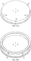
- the rim 40 is a split rim or two piece rim 44a, 44b that are joined together by fasteners to form a tire engaging surface surrounded by tire-engaging flanges.
- the rim 40 is preferably of a substantially rigid material such as steel and has a tire-supporting outer circumferential surface.
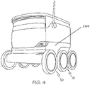
- the tire of the present invention is provided on a mobile delivery vehicle 100 as shown in FIG. 4 .
- the mobile delivery vehicle 100 has at least three, preferably four or more non-pneumatic tire and rim assemblies of the present invention, and more particularly, six non-pneumatic tire and rim assemblies.
- the tire has an outer rubber tread and a spoke ring structure that is injection molded and formed of a TPU or polyurethane material having a tensile modulus of 10-100 MPA.
- the spoke ring structure may also be three dimensionally printed.
- the non-pneumatic tire and rim of the present invention has a spring rate in the range of 43780 N/m to 52520 N/m (250 to 300 pounds per inch).
- the non-pneumatic tire and rim of the present invention has an axial width of 38.1 mm (or from 30 to 50 mm) with 15 x to 24 x shaped spokes having a radial height of 25.4 mm (or from 15 to 40 mm). While the non-pneumatic tire and wheel assembly is described as having X shaped spokes, other spoke designs could be used.
- the rim has an outer diameter of 127 mm (or 76.2 mm to 203.2 mm) but could be sized to be smaller in the outer diameter to provide a greater radial height of the spoke ring structure.
Landscapes
- Engineering & Computer Science (AREA)
- Mechanical Engineering (AREA)
- Chemical & Material Sciences (AREA)
- Manufacturing & Machinery (AREA)
- Materials Engineering (AREA)
- Tires In General (AREA)
Abstract
Description
- The invention relates in general to a vehicle wheel, and more particularly to a non-pneumatic tire and rim assembly and to its method of manufacturing.
- The pneumatic tire has been the solution of choice for vehicular mobility for over a century. The pneumatic tire is a tensile structure. The pneumatic tire has at least four characteristics that make the pneumatic tire so dominate today. Pneumatic tires are efficient at carrying loads, because all of the tire structure is involved in carrying the load. Pneumatic tires are also desirable because they have low contact pressure, resulting in lower wear on roads due to the distribution of the load of the vehicle. Pneumatic tires also have low stiffness, which ensures a comfortable ride in a vehicle. The primary drawback to a pneumatic tire is that it requires compressed fluid. A conventional pneumatic tire is rendered useless after a complete loss of inflation pressure.
- A tire designed to operate without inflation pressure may eliminate many of the problems and compromises associated with a pneumatic tire. Neither pressure maintenance nor pressure monitoring is required. Structurally supported tires such as solid tires or other elastomeric structures to date have not provided the levels of performance required from a conventional pneumatic tire. A structurally supported tire solution that delivers pneumatic tire-like performance would be a desirous improvement.
- Non-pneumatic tires are typically defined by their load carrying efficiency. "Bottom loaders" are essentially rigid structures that carry a majority of the load in the portion of the structure below the hub. "Top loaders" are designed so that all of the structure is involved in carrying the load. Top loaders thus have a higher load carrying efficiency than bottom loaders, allowing a design that has less mass.
- Thus, an improved non-pneumatic tire is desired that has all the features of the pneumatic tires without the drawback of the need for air inflation is desired. It is also desired to have an improved non-pneumatic tire that has longer tread life as compared to a pneumatic tire of the same size.
- The invention relates to a non-pneumatic tire and wheel assembly in accordance with claim 1 and to a method in accordance with
claim 10. - Dependent claims refer to preferred embodiments of the invention.
- The invention provides in a first aspect a non-pneumatic tire and wheel assembly comprising: a rim, a spoke ring structure having an inner ring that is mounted on an outer surface of the rim, wherein the inner ring has one or more retention nubs aligned for reception in complementary shaped grooves on the outer surface of the rim, wherein the spoke ring structure has a plurality of spoke members, and an outer tread ring mounted on the outer circumference of the spoke ring.
- "Aspect Ratio" means the ratio of a tire's section height to its section width.
- "Axial" and "axially" means the lines or directions that are parallel to the axis of rotation of the tire.
- "Circumferential" means lines or directions extending along the perimeter of the surface of the annular tread perpendicular to the axial direction.
- "Radial" and "radially" mean directions radially toward or away from the axis of rotation of the tire.
- The invention will be described by way of example and with reference to the accompanying drawings in which:
-
FIG. 1 is a front view of a non-pneumatic tire and rim assembly of the present invention; -
FIG. 2 is a rear view of the non-pneumatic tire and rim assembly ofFIG. 1 ; -
FIG. 3 is an exploded view of the non-pneumatic tire and rim assembly ofFIG. 1 ; -
FIG. 4 is an exemplary vehicle with multiple non-pneumatic tire and rim assemblies of the present invention; -
FIG. 5A is a front view of a spoke ring assembly, whileFIG. 5B is a perspective view of the spoke ring assembly ofFIG. 5A ; -
FIG. 6A is a perspective view of the left rim half, whileFIG. 6B is a perspective view of the right rim half; -
FIG. 7 is a close-up view cut away section of the non-pneumatic tire and rim assembly; -
FIG. 8 is a perspective view of the split rim; -
FIG. 9 is a close-up perspective view of the non-pneumatic tire and rim assembly; and -
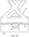
FIG. 10 is a close-up view of the retention nubs located on the inner ring of the spoke ring structure and the retention groove of the rim. - Referring to
FIGS. 1 ,2 and3 , a non-pneumatic tire andrim assembly 10 of the present invention is shown. The non-pneumatic tire andrim assembly 10 includes an outerannular tread ring 30, aspoke ring structure 20, and arim 40. The outerannular tread ring 30 is preferably a one piece annular structure that is formed of a polymer, rubber or other desired elastomer. Thetread ring 30 may be molded and cured as a one piece ring, and is mounted on the outer periphery of the spoke ring. The outer surface of thetread ring 30 may include tread elements such as ribs, blocks, lugs, grooves, and sipes as desired in order to improve the performance of the tire in various conditions. - The
tread ring 30 may include anoptional shear ring 35, as shown inFIG. 7 . Theoptional shear ring 35 is preferably a discrete ring, formed of a different material than thetread ring 30. Alternatively, theoptional shear ring 35 may be integrally formed with thespoke ring 20, and located on the outer annular surface of the spoke ring. Theoptional shear ring 35 is preferably located between the outer circumference of the spoke ring, and the inner circumference of the tread ring. Theoptional shear ring 35 may optionally include one or more annular reinforcement layers, which could be fabric with optional parallel reinforcement cables preferably oriented in the zero degree (circumferential) orientation. Thetread ring 30,optional shear ring 35 and spoke structure may be integrally formed via injection molding or three dimensional printing, or they may be formed in discrete components by injection molding or three dimensional printing and then assembled together. - The non-pneumatic tire and
rim assembly 10 further includes aspoke ring structure 20. Thespoke ring structure 20 has aninner ring 22 that is mounted on the rim. Theinner ring 22 has a plurality of retaining nubs orprojections 24, as shown inFIG. 2 andFIG. 10 . In this example, thenubs 24 are hemispherical or rounded in cross-sectional shape. However, thenubs 24 may be any desired shape. The retainingnubs 24 are received in complementary shapedgrooves 42 located on theouter surface 44 of therim 40. - The spoke ring structure further includes an
outer ring 26 having an outer surface that is joined to theinner tread surface 32 by an adhesive polymer. The spoke ring structure further includes a plurality of spoke members that extend between theinner ring 22 to theouter ring 26. In a first example shown inFIGS. 2 and7 , the spoke ring structure has afirst spoke member 60 that extends from theinner ring 22 to theouter ring 26 at an angle. The spoke ring structure includes asecond spoke member 62 that also extends from the inner ring to theouter ring 26 at an angle. The first andsecond spoke member junction 70 to form an X shaped spoke. The first and second spokemembers - The
spoke ring structure 20 is preferably an integrally formed annular structure made of a resilient elastomeric material or moldable polymeric material such as natural rubber, styrene butadiene rubber, polybutadiene rubber or EPDM rubber or a blend of two or more of these rubbers which can be utilized in either injection molding or compression molding. Thespoke ring structure 20 has an axial thickness equal to the axial thickness of the non-pneumatic tire. Thespoke ring structure 20 has a plurality of spokes that connect aninner ring 22 and anouter ring 24. - The spoke disks are preferably formed of an elastic material, more preferably, a thermoplastic elastomer. The material of the spoke disks is selected based upon one or more of the following material properties. The tensile (Young's) modulus of the spoke disk material is preferably in the range of 15 MPa to 100 MPa, and more preferably in the range of 30 MPa to 70 MPa.
- The
rim 40 is a split rim or twopiece rim rim 40 is preferably of a substantially rigid material such as steel and has a tire-supporting outer circumferential surface. - In one example, the tire of the present invention is provided on a
mobile delivery vehicle 100 as shown inFIG. 4 . Themobile delivery vehicle 100 has at least three, preferably four or more non-pneumatic tire and rim assemblies of the present invention, and more particularly, six non-pneumatic tire and rim assemblies. The tire has an outer rubber tread and a spoke ring structure that is injection molded and formed of a TPU or polyurethane material having a tensile modulus of 10-100 MPA. The spoke ring structure may also be three dimensionally printed. The non-pneumatic tire and rim of the present invention has a spring rate in the range of 43780 N/m to 52520 N/m (250 to 300 pounds per inch). The non-pneumatic tire and rim of the present invention has an axial width of 38.1 mm (or from 30 to 50 mm) with 15 x to 24 x shaped spokes having a radial height of 25.4 mm (or from 15 to 40 mm). While the non-pneumatic tire and wheel assembly is described as having X shaped spokes, other spoke designs could be used. The rim has an outer diameter of 127 mm (or 76.2 mm to 203.2 mm) but could be sized to be smaller in the outer diameter to provide a greater radial height of the spoke ring structure.
Claims (10)
- A non-pneumatic tire and wheel assembly comprising a rim (40), a spoke ring structure (20) having an inner ring (22) that is mounted on an outer surface of the rim (40), wherein the inner ring (22) has one or more retention nubs (24) aligned for reception in complementary shaped grooves (42) on the outer surface of the rim (40), wherein the spoke ring structure (20) has a plurality of spoke members (60, 62) and an outer tread ring (30) mounted on the outer circumference of the spoke ring structure (20).
- The non-pneumatic tire and wheel assembly of claim 1 wherein the retention nubs (24) are round in cross-section.
- The non-pneumatic tire and wheel assembly of at least one of the previous claims wherein the spoke members (60, 62) are joined together at a junction (70) to form an X shaped spoke.
- The non-pneumatic tire and wheel assembly of at least one of the previous claims wherein the rim (40) is a two piece rim (44a, 44b).
- The non-pneumatic tire and wheel assembly of at least one of the previous claims further including a shear ring (35).
- The non-pneumatic tire and wheel assembly of claim 5 wherein the shear ring (35) is located between the outer tread ring (30) and the spoke ring structure (20).
- The non-pneumatic tire and wheel assembly of claim 5 or 6 wherein the shear ring (35) is integrally formed with the spoke ring structure (20).
- The non-pneumatic tire and wheel assembly of at least one of the previous claims wherein the spoke ring structure (20) is formed of a polymer material having a tensile modulus in the range of from 15 to 100 MPa.
- The non-pneumatic tire and wheel assembly of at least one of the previous claims wherein the shear ring (35) is mounted radially outward of the spoke ring structure (20), the shear ring (35) being integrally formed with the spoke ring structure (20).
- A method of manufacturing the non-pneumatic tire and wheel assembly of at least one of the previous claims wherein the non-pneumatic tire and wheel assembly (10) is formed by three-dimensional printing.
Applications Claiming Priority (2)
| Application Number | Priority Date | Filing Date | Title |
|---|---|---|---|
| US202163193909P | 2021-05-27 | 2021-05-27 | |
| US17/656,437 US20220379661A1 (en) | 2021-05-27 | 2022-03-25 | Non-pneumatic tire and rim assembly |
Publications (2)
| Publication Number | Publication Date |
|---|---|
| EP4094956A1 true EP4094956A1 (en) | 2022-11-30 |
| EP4094956B1 EP4094956B1 (en) | 2024-06-26 |
Family
ID=81750632
Family Applications (1)
| Application Number | Title | Priority Date | Filing Date |
|---|---|---|---|
| EP22174604.3A Active EP4094956B1 (en) | 2021-05-27 | 2022-05-20 | Non-pneumatic tire and rim assembly |
Country Status (2)
| Country | Link |
|---|---|
| US (1) | US20220379661A1 (en) |
| EP (1) | EP4094956B1 (en) |
Cited By (3)
| Publication number | Priority date | Publication date | Assignee | Title |
|---|---|---|---|---|
| EP4177078A1 (en) * | 2021-11-08 | 2023-05-10 | The Goodyear Tire & Rubber Company | Non-pneumatic tire and wheel assembly amd method of manufacturing |
| WO2024126385A1 (en) * | 2022-12-14 | 2024-06-20 | Compagnie Generale Des Etablissements Michelin | Method for manufacturing an airless tyre by additive manufacturing |
| WO2024126389A1 (en) * | 2022-12-14 | 2024-06-20 | Compagnie Generale Des Etablissements Michelin | Method for additively manufacturing a carcass of an airless tyre for a vehicle |
Citations (9)
| Publication number | Priority date | Publication date | Assignee | Title |
|---|---|---|---|---|
| JP2009269413A (en) * | 2008-04-30 | 2009-11-19 | Toyo Tire & Rubber Co Ltd | Non-pneumatic tire, rim wheel, and wheel |
| CN103350615A (en) * | 2013-07-13 | 2013-10-16 | 王晓辉 | Non-pneumatic and safely combined wheel |
| US20160243890A1 (en) * | 2013-10-22 | 2016-08-25 | Bridgestone Corporation | Non-pneumatic tire |
| US20180029419A1 (en) * | 2016-07-29 | 2018-02-01 | Kumho Tire Co., Inc. | Non-pneumatic tire |
| CN207594648U (en) * | 2017-11-16 | 2018-07-10 | 青岛双星轮胎工业有限公司 | Non-inflatable tyre |
| US20180354304A1 (en) * | 2015-12-29 | 2018-12-13 | Bridgestone Americas Tire Operations, Llc | Composite layer tire |
| US20190143619A1 (en) * | 2017-11-16 | 2019-05-16 | Kumho Tire Co., Inc. | Airless tire manufacturing method |
| JP2021000752A (en) * | 2019-06-21 | 2021-01-07 | 日産自動車株式会社 | Method for manufacturing airless tire and airless tire |
| US20210061009A1 (en) * | 2019-08-30 | 2021-03-04 | The Goodyear Tire & Rubber Company | Nonpneumatic tire and wheel assembly with integrated spoke structure |
Family Cites Families (11)
| Publication number | Priority date | Publication date | Assignee | Title |
|---|---|---|---|---|
| US4226273A (en) * | 1978-06-30 | 1980-10-07 | The Goodyear Tire & Rubber Company | Nonpneumatic tire and rim assembly |
| CA2043082A1 (en) * | 1991-02-27 | 1992-08-28 | James Edward Duddey | Non-pneumatic spare tire |
| EP1420964B1 (en) * | 2001-08-24 | 2007-11-14 | Société de Technologie Michelin | Non-pneumatic tire |
| US6681822B2 (en) * | 2002-04-26 | 2004-01-27 | The Goodyear Tire & Rubber Company | Non-pneumatic spare tire |
| US7878600B2 (en) * | 2007-06-05 | 2011-02-01 | Stellana U.S. Inc. | Mechanical fastener for polyurethane wheels |
| WO2010012091A1 (en) * | 2008-08-01 | 2010-02-04 | Mindmatter Innovates Inc. | Reactive planar suspension for a wheel |
| US20170008342A1 (en) * | 2015-07-10 | 2017-01-12 | Caterpillar Inc. | Non-pneumatic tire including shear band |
| JP6754686B2 (en) * | 2016-12-13 | 2020-09-16 | Toyo Tire株式会社 | Non-pneumatic tires |
| CN107757259B (en) * | 2017-11-16 | 2019-11-19 | 青岛双星轮胎工业有限公司 | Non-inflatable tyre |
| CN110435358B (en) * | 2019-08-09 | 2021-08-31 | 浙江竤屹科技有限公司 | Airless tire and production process thereof |
| US11827062B2 (en) * | 2019-08-29 | 2023-11-28 | The Goodyear Tire & Rubber Company | Non-pneumatic tire with a flexible looped spoke and method of forming |
-
2022
- 2022-03-25 US US17/656,437 patent/US20220379661A1/en active Pending
- 2022-05-20 EP EP22174604.3A patent/EP4094956B1/en active Active
Patent Citations (9)
| Publication number | Priority date | Publication date | Assignee | Title |
|---|---|---|---|---|
| JP2009269413A (en) * | 2008-04-30 | 2009-11-19 | Toyo Tire & Rubber Co Ltd | Non-pneumatic tire, rim wheel, and wheel |
| CN103350615A (en) * | 2013-07-13 | 2013-10-16 | 王晓辉 | Non-pneumatic and safely combined wheel |
| US20160243890A1 (en) * | 2013-10-22 | 2016-08-25 | Bridgestone Corporation | Non-pneumatic tire |
| US20180354304A1 (en) * | 2015-12-29 | 2018-12-13 | Bridgestone Americas Tire Operations, Llc | Composite layer tire |
| US20180029419A1 (en) * | 2016-07-29 | 2018-02-01 | Kumho Tire Co., Inc. | Non-pneumatic tire |
| CN207594648U (en) * | 2017-11-16 | 2018-07-10 | 青岛双星轮胎工业有限公司 | Non-inflatable tyre |
| US20190143619A1 (en) * | 2017-11-16 | 2019-05-16 | Kumho Tire Co., Inc. | Airless tire manufacturing method |
| JP2021000752A (en) * | 2019-06-21 | 2021-01-07 | 日産自動車株式会社 | Method for manufacturing airless tire and airless tire |
| US20210061009A1 (en) * | 2019-08-30 | 2021-03-04 | The Goodyear Tire & Rubber Company | Nonpneumatic tire and wheel assembly with integrated spoke structure |
Cited By (5)
| Publication number | Priority date | Publication date | Assignee | Title |
|---|---|---|---|---|
| EP4177078A1 (en) * | 2021-11-08 | 2023-05-10 | The Goodyear Tire & Rubber Company | Non-pneumatic tire and wheel assembly amd method of manufacturing |
| WO2024126385A1 (en) * | 2022-12-14 | 2024-06-20 | Compagnie Generale Des Etablissements Michelin | Method for manufacturing an airless tyre by additive manufacturing |
| WO2024126389A1 (en) * | 2022-12-14 | 2024-06-20 | Compagnie Generale Des Etablissements Michelin | Method for additively manufacturing a carcass of an airless tyre for a vehicle |
| FR3143414A1 (en) * | 2022-12-14 | 2024-06-21 | Compagnie Generale Des Etablissements Michelin | Process for producing an airless tire by additive manufacturing |
| FR3143412A1 (en) * | 2022-12-14 | 2024-06-21 | Compagnie Generale Des Etablissements Michelin | Optimized process for producing an airless tire by additive manufacturing |
Also Published As
| Publication number | Publication date |
|---|---|
| US20220379661A1 (en) | 2022-12-01 |
| EP4094956B1 (en) | 2024-06-26 |
Similar Documents
| Publication | Publication Date | Title |
|---|---|---|
| EP4094956A1 (en) | Non-pneumatic tire and rim assembly | |
| US10421319B2 (en) | Non-pneumatic tire with integrated polymeric flexible wheel center mount | |
| US20180361792A1 (en) | Tension-based non-pneumatic tire | |
| US9004127B2 (en) | Tension-based non-pneumatic tire | |
| EP2141030B1 (en) | Non-pneumatic tire and method of manufacturing same | |
| KR101931696B1 (en) | An airless tyre for vehicles | |
| EP3142867B1 (en) | Non-pneumatic tire with partially compliant hub | |
| US10150334B2 (en) | Non-pneumatic support structure | |
| US4287927A (en) | Multiple ring tire | |
| EP4023461B1 (en) | Non-pneumatic tire and wheel assembly with reinforced spoke structure | |
| CN100357116C (en) | Tire/wheel assembly body and interior body for noise reduction | |
| EP3838618B1 (en) | Non-pneumatic tire and wheel assembly with integrated spoke structure | |
| CN109466250A (en) | Non-inflatable tyre | |
| EP3785932B1 (en) | Non-pneumatic tire and wheel assembly with integrated spoke structure | |
| EP4105038B1 (en) | Non-pneumatic tire and rim assembly | |
| EP4177078A1 (en) | Non-pneumatic tire and wheel assembly amd method of manufacturing | |
| US20210323352A1 (en) | Tension-based non-pneumatic tire | |
| EP4177077A1 (en) | Non-pneumatic tire and wheel assembly and method of manufacturing | |
| CN114683770B (en) | Inflation-free tyre | |
| JP7561026B2 (en) | NON-PNEUMATIC TIRE AND METHOD FOR MANUFACTURING NON-PNEUMATIC TIRE | |
| CN111936326B (en) | Rolling assembly | |
| US20200391551A1 (en) | Non-pneumatic support structure | |
| JP2003341310A (en) | Support and pneumatic run-flat tire | |
| CN115923400A (en) | Non-pneumatic tire and vehicle | |
| KR20160109795A (en) | Outer wheel with two stage structure and Non-pneumatic wheels with two stage outer wheels |
Legal Events
| Date | Code | Title | Description |
|---|---|---|---|
| PUAI | Public reference made under article 153(3) epc to a published international application that has entered the european phase |
Free format text: ORIGINAL CODE: 0009012 |
|
| STAA | Information on the status of an ep patent application or granted ep patent |
Free format text: STATUS: THE APPLICATION HAS BEEN PUBLISHED |
|
| AK | Designated contracting states |
Kind code of ref document: A1 Designated state(s): AL AT BE BG CH CY CZ DE DK EE ES FI FR GB GR HR HU IE IS IT LI LT LU LV MC MK MT NL NO PL PT RO RS SE SI SK SM TR |
|
| STAA | Information on the status of an ep patent application or granted ep patent |
Free format text: STATUS: REQUEST FOR EXAMINATION WAS MADE |
|
| 17P | Request for examination filed |
Effective date: 20230530 |
|
| RBV | Designated contracting states (corrected) |
Designated state(s): AL AT BE BG CH CY CZ DE DK EE ES FI FR GB GR HR HU IE IS IT LI LT LU LV MC MK MT NL NO PL PT RO RS SE SI SK SM TR |
|
| GRAP | Despatch of communication of intention to grant a patent |
Free format text: ORIGINAL CODE: EPIDOSNIGR1 |
|
| STAA | Information on the status of an ep patent application or granted ep patent |
Free format text: STATUS: GRANT OF PATENT IS INTENDED |
|
| RIC1 | Information provided on ipc code assigned before grant |
Ipc: B33Y 80/00 20150101ALI20231220BHEP Ipc: B29D 30/02 20060101ALI20231220BHEP Ipc: B60C 7/24 20060101ALI20231220BHEP Ipc: B60C 7/14 20060101AFI20231220BHEP |
|
| INTG | Intention to grant announced |
Effective date: 20240124 |
|
| GRAS | Grant fee paid |
Free format text: ORIGINAL CODE: EPIDOSNIGR3 |
|
| GRAA | (expected) grant |
Free format text: ORIGINAL CODE: 0009210 |
|
| STAA | Information on the status of an ep patent application or granted ep patent |
Free format text: STATUS: THE PATENT HAS BEEN GRANTED |
|
| AK | Designated contracting states |
Kind code of ref document: B1 Designated state(s): AL AT BE BG CH CY CZ DE DK EE ES FI FR GB GR HR HU IE IS IT LI LT LU LV MC MK MT NL NO PL PT RO RS SE SI SK SM TR |
|
| REG | Reference to a national code |
Ref country code: GB Ref legal event code: FG4D |
|
| REG | Reference to a national code |
Ref country code: CH Ref legal event code: EP |
|
| PG25 | Lapsed in a contracting state [announced via postgrant information from national office to epo] |
Ref country code: BG Free format text: LAPSE BECAUSE OF FAILURE TO SUBMIT A TRANSLATION OF THE DESCRIPTION OR TO PAY THE FEE WITHIN THE PRESCRIBED TIME-LIMIT Effective date: 20240626 |
|
| PG25 | Lapsed in a contracting state [announced via postgrant information from national office to epo] |
Ref country code: FI Free format text: LAPSE BECAUSE OF FAILURE TO SUBMIT A TRANSLATION OF THE DESCRIPTION OR TO PAY THE FEE WITHIN THE PRESCRIBED TIME-LIMIT Effective date: 20240626 Ref country code: HR Free format text: LAPSE BECAUSE OF FAILURE TO SUBMIT A TRANSLATION OF THE DESCRIPTION OR TO PAY THE FEE WITHIN THE PRESCRIBED TIME-LIMIT Effective date: 20240626 |
|
| REG | Reference to a national code |
Ref country code: LT Ref legal event code: MG9D |
|
| PG25 | Lapsed in a contracting state [announced via postgrant information from national office to epo] |
Ref country code: GR Free format text: LAPSE BECAUSE OF FAILURE TO SUBMIT A TRANSLATION OF THE DESCRIPTION OR TO PAY THE FEE WITHIN THE PRESCRIBED TIME-LIMIT Effective date: 20240927 |