EP4094876B1 - Gesteuerte photomechanische und photothermale gewebebehandlung im picosekundenbereich - Google Patents
Gesteuerte photomechanische und photothermale gewebebehandlung im picosekundenbereich Download PDFInfo
- Publication number
- EP4094876B1 EP4094876B1 EP22157332.2A EP22157332A EP4094876B1 EP 4094876 B1 EP4094876 B1 EP 4094876B1 EP 22157332 A EP22157332 A EP 22157332A EP 4094876 B1 EP4094876 B1 EP 4094876B1
- Authority
- EP
- European Patent Office
- Prior art keywords
- tissue
- laser
- picoseconds
- picosecond
- pulse
- Prior art date
- Legal status (The legal status is an assumption and is not a legal conclusion. Google has not performed a legal analysis and makes no representation as to the accuracy of the status listed.)
- Active
Links
Images


Classifications
-
- A—HUMAN NECESSITIES
- A61—MEDICAL OR VETERINARY SCIENCE; HYGIENE
- A61B—DIAGNOSIS; SURGERY; IDENTIFICATION
- A61B18/00—Surgical instruments, devices or methods for transferring non-mechanical forms of energy to or from the body
- A61B18/18—Surgical instruments, devices or methods for transferring non-mechanical forms of energy to or from the body by applying electromagnetic radiation, e.g. microwaves
- A61B18/20—Surgical instruments, devices or methods for transferring non-mechanical forms of energy to or from the body by applying electromagnetic radiation, e.g. microwaves using laser
- A61B18/22—Surgical instruments, devices or methods for transferring non-mechanical forms of energy to or from the body by applying electromagnetic radiation, e.g. microwaves using laser the beam being directed along or through a flexible conduit, e.g. an optical fibre; Couplings or hand-pieces therefor
- A61B18/26—Surgical instruments, devices or methods for transferring non-mechanical forms of energy to or from the body by applying electromagnetic radiation, e.g. microwaves using laser the beam being directed along or through a flexible conduit, e.g. an optical fibre; Couplings or hand-pieces therefor for producing a shock wave, e.g. laser lithotripsy
-
- B—PERFORMING OPERATIONS; TRANSPORTING
- B23—MACHINE TOOLS; METAL-WORKING NOT OTHERWISE PROVIDED FOR
- B23K—SOLDERING OR UNSOLDERING; WELDING; CLADDING OR PLATING BY SOLDERING OR WELDING; CUTTING BY APPLYING HEAT LOCALLY, e.g. FLAME CUTTING; WORKING BY LASER BEAM
- B23K26/00—Working by laser beam, e.g. welding, cutting or boring
- B23K26/02—Positioning or observing the workpiece, e.g. with respect to the point of impact; Aligning, aiming or focusing the laser beam
- B23K26/06—Shaping the laser beam, e.g. by masks or multi-focusing
- B23K26/062—Shaping the laser beam, e.g. by masks or multi-focusing by direct control of the laser beam
- B23K26/0622—Shaping the laser beam, e.g. by masks or multi-focusing by direct control of the laser beam by shaping pulses
- B23K26/0624—Shaping the laser beam, e.g. by masks or multi-focusing by direct control of the laser beam by shaping pulses using ultrashort pulses, i.e. pulses of 1ns or less
-
- A—HUMAN NECESSITIES
- A61—MEDICAL OR VETERINARY SCIENCE; HYGIENE
- A61B—DIAGNOSIS; SURGERY; IDENTIFICATION
- A61B18/00—Surgical instruments, devices or methods for transferring non-mechanical forms of energy to or from the body
- A61B18/18—Surgical instruments, devices or methods for transferring non-mechanical forms of energy to or from the body by applying electromagnetic radiation, e.g. microwaves
- A61B18/20—Surgical instruments, devices or methods for transferring non-mechanical forms of energy to or from the body by applying electromagnetic radiation, e.g. microwaves using laser
- A61B18/203—Surgical instruments, devices or methods for transferring non-mechanical forms of energy to or from the body by applying electromagnetic radiation, e.g. microwaves using laser applying laser energy to the outside of the body
-
- A—HUMAN NECESSITIES
- A61—MEDICAL OR VETERINARY SCIENCE; HYGIENE
- A61B—DIAGNOSIS; SURGERY; IDENTIFICATION
- A61B18/00—Surgical instruments, devices or methods for transferring non-mechanical forms of energy to or from the body
- A61B2018/00315—Surgical instruments, devices or methods for transferring non-mechanical forms of energy to or from the body for treatment of particular body parts
- A61B2018/00345—Vascular system
- A61B2018/00398—Blood
-
- A—HUMAN NECESSITIES
- A61—MEDICAL OR VETERINARY SCIENCE; HYGIENE
- A61B—DIAGNOSIS; SURGERY; IDENTIFICATION
- A61B18/00—Surgical instruments, devices or methods for transferring non-mechanical forms of energy to or from the body
- A61B2018/00315—Surgical instruments, devices or methods for transferring non-mechanical forms of energy to or from the body for treatment of particular body parts
- A61B2018/00452—Skin
- A61B2018/00458—Deeper parts of the skin, e.g. treatment of vascular disorders or port wine stains
-
- A—HUMAN NECESSITIES
- A61—MEDICAL OR VETERINARY SCIENCE; HYGIENE
- A61B—DIAGNOSIS; SURGERY; IDENTIFICATION
- A61B18/00—Surgical instruments, devices or methods for transferring non-mechanical forms of energy to or from the body
- A61B2018/00571—Surgical instruments, devices or methods for transferring non-mechanical forms of energy to or from the body for achieving a particular surgical effect
- A61B2018/00577—Ablation
-
- A—HUMAN NECESSITIES
- A61—MEDICAL OR VETERINARY SCIENCE; HYGIENE
- A61B—DIAGNOSIS; SURGERY; IDENTIFICATION
- A61B18/00—Surgical instruments, devices or methods for transferring non-mechanical forms of energy to or from the body
- A61B2018/00636—Sensing and controlling the application of energy
- A61B2018/00696—Controlled or regulated parameters
- A61B2018/00702—Power or energy
-
- A—HUMAN NECESSITIES
- A61—MEDICAL OR VETERINARY SCIENCE; HYGIENE
- A61B—DIAGNOSIS; SURGERY; IDENTIFICATION
- A61B18/00—Surgical instruments, devices or methods for transferring non-mechanical forms of energy to or from the body
- A61B18/18—Surgical instruments, devices or methods for transferring non-mechanical forms of energy to or from the body by applying electromagnetic radiation, e.g. microwaves
- A61B18/20—Surgical instruments, devices or methods for transferring non-mechanical forms of energy to or from the body by applying electromagnetic radiation, e.g. microwaves using laser
- A61B18/22—Surgical instruments, devices or methods for transferring non-mechanical forms of energy to or from the body by applying electromagnetic radiation, e.g. microwaves using laser the beam being directed along or through a flexible conduit, e.g. an optical fibre; Couplings or hand-pieces therefor
- A61B18/26—Surgical instruments, devices or methods for transferring non-mechanical forms of energy to or from the body by applying electromagnetic radiation, e.g. microwaves using laser the beam being directed along or through a flexible conduit, e.g. an optical fibre; Couplings or hand-pieces therefor for producing a shock wave, e.g. laser lithotripsy
- A61B2018/263—Surgical instruments, devices or methods for transferring non-mechanical forms of energy to or from the body by applying electromagnetic radiation, e.g. microwaves using laser the beam being directed along or through a flexible conduit, e.g. an optical fibre; Couplings or hand-pieces therefor for producing a shock wave, e.g. laser lithotripsy the conversion of laser energy into mechanical shockwaves taking place in a liquid
Definitions
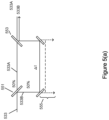
- the system optionally includes a wavelength-shifting resonator 72 for receiving the picosecond pulses generated by the pump radiation source 71 and emitting radiation at a second wavelength in response thereto to the treatment beam delivery system 73.
- the pump radiation source 71 generally generates one or more pulses at a first wavelength to be transmitted to the wavelength-shifting resonator 72, and can have a variety of configurations.
- the pulses generated by the pump radiation source 71 can have a variety of wavelengths, pulse durations, and energies.
- the pump radiation source 71 can be selected to emit substantially monochromatic optical radiation having a wavelength that can be efficiently absorbed by the wavelength-shifting resonator 72 in a minimum number of passes through the gain medium.
- the pump radiation source 71 can be operated so as to generate pulses at various energies, depending for example, on the amount of energy required to stimulate emission by the wavelength-shifting resonator 72 and the amount of energy required to perform a particular treatment in light of the efficiency of the system 70 as a whole.
- the pump radiation source 71 can be configured to generate picosecond pulses of optical radiation. That is, the pump radiation source can generate pulsed radiation exhibiting a pulse duration less than about 1000 picoseconds (e.g., within a range of about 500 picoseconds to about 800 picoseconds).
- the pump radiation source 71 for generating the pump pulse at a first wavelength can include a resonator (or laser cavity containing a lasing medium), an electro-optical device (e.g., a Pockels cell), and a polarizer (e.g., a thin-film polarizer), as described for example with reference to FIG. 2 of U.S. Patent No. 7,586,957, issued on September 8, 2009 and entitled "Picosecond Laser Apparatus and Methods for Its Operation and Use," the contents of which are hereby incorporated by reference in its entirety.
- the lasing or gain medium of the pump radiation source 71 can be pumped by any conventional pumping device such as an optical pumping device (e.g., a flash lamp) or an electrical or injection pumping device.
- the pump radiation source 71 comprises a solid state lasing medium and an optical pumping device.
- Exemplary solid state lasers include an alexandrite or a titanium doped sapphire (TIS) crystal, Nd:YAG lasers, Nd:YAP, Nd:YAlO 3 lasers, Nd:YAF lasers, and other rare earth and transition metal ion dopants (e.g., erbium, chromium, and titanium) and other crystal and glass media hosts (e.g., vanadate crystals such as YVO 4 , fluoride glasses such as ZBLN, silica glasses, and other minerals such as ruby).
- TIS titanium doped sapphire
- At opposite ends of the optical axis of the resonator can be first and second mirrors having substantially complete reflectivity such that a laser pulse traveling from the lasing medium towards second mirror will first pass through the polarizer, then the Pockels cell, reflect at second mirror, traverse Pockels cell a second time, and finally pass through polarizer a second time before returning to the gain medium.
- some portion (or rejected fraction) of the energy in the pulse will be rejected at the polarizer and exit the resonator along an output path to be transmitted to the wavelength-shifting resonator 72.
- the laser energy, oscillating in the resonator of the pump radiation source 71 under amplification conditions, has reached a desired or maximum amplitude, it can thereafter be extracted for transmission to the wavelength-shifting resonator 72 by changing the bias voltage to the Pockels cell such that the effective reflectivity of the second mirror is selected to output laser radiation having the desired pulse duration and energy output.
- the wavelength-shifting resonator 72 can also have a variety of configurations in accordance with the applicant's present teachings, but is generally configured to receive the pulses generated by the pump radiation source 71 and emit radiation at a second wavelength in response thereto.
- the wavelength-shifting resonator 72 comprises a lasing medium and a resonant cavity extending between an input end and an output end, wherein the lasing medium absorbs the pulses of optical energy received from the pump radiation source 71 and, through a process of stimulated emission, emits one or more pulses of optical laser radiation exhibiting a second wavelength.
- the lasing medium of the wavelength-shifting resonator can comprise a neodymium-doped crystal, including by way of non-limiting example solid state crystals of neodymium-doped yttrium-aluminum garnet (Nd:YAG), neodymium-doped pervoskite (Nd:YAP or Nd:YAlO 3 ), neodymium-doped yttrium-lithium-fluoride (Nd:YAF), and neodymium-doped vanadate (Nd:YVO 4 ) crystals.
- Nd:YAG neodymium-doped yttrium-aluminum garnet
- Nd:YAP or Nd:YAlO 3 neodymium-doped pervoskite
- Nd:YAF neodymium-doped yttrium-lithium-fluoride
- the lasing medium of the wavelength-shifting resonator 72 can also have a variety of shapes (e.g., rods, slabs, cubes) but is generally long enough along the optical axis such that the lasing medium absorbs a substantial portion (e.g., most, greater than 80%, greater than 90%) of the pump pulse in two passes through the crystal.
- a substantial portion e.g., most, greater than 80%, greater than 90%
- the roundtrip time can be less than 5 times shorter than the duration of the picosecond pump pulses input into the resonant cavity (e.g., less than 10 times shorter).
- the output pulse extracted from the resonant cavity can have an ultra-short duration without the need for additional pulse-shaping (e.g., without use of a modelocker, Q-switch, pulse picker or any similar device of active or passive type).
- the pulses generated by the wavelength-shifting resonator can have a pulse duration less than 1000 picoseconds (e.g., about 500 picoseconds, about 750 picoseconds).
- the picosecond laser pulses After the picosecond laser pulses are extracted from the wavelength-shifting resonator 72, they can be transmitted directly to the treatment beam delivery system 73 for application to the patient's skin, for example, or they can be further processed through one or more optional optical elements shown in phantom, such as an amplifier 74, frequency doubling waveguide 75, and/or filter (not shown) prior to being transmitted to the treatment beam delivery system.
- one or more optional optical elements shown in phantom such as an amplifier 74, frequency doubling waveguide 75, and/or filter (not shown) prior to being transmitted to the treatment beam delivery system.
- any number of known downstream optical (e.g., lenses) electro-optical and/or acousto-optic elements modified in accordance with the present teachings can be used to focus, shape, and/or alter (e.g., amplify) the pulsed beam for ultimate delivery to the patient's skin to ensure a sufficient laser output, while nonetheless maintaining the ultrashort pulse duration generated in the wavelength-shifting resonator 72.
- an optical element 76 in phantom
- Lasers are recognized as controllable sources of radiation that are relatively monochromatic and coherent (i.e., have little divergence). Laser energy is applied in an ever-increasing number of areas in diverse fields such as telecommunications, data storage and retrieval, entertainment, research, and many others. In the area of medicine, lasers have proven useful in surgical and cosmetic procedures where a precise beam of high energy radiation causes localized heating and ultimately the destruction of unwanted tissues. Such tissues include, for example, subretinal scar tissue that forms in age-related macular degeneration (AMD) or the constituents of ectatic blood vessels that constitute vascular lesions.
- AMD age-related macular degeneration
- the fluence, or energy per unit area, used to accomplish this denaturation or dispersion is generally based on the amount required to achieve the desired targeted tissue temperature, before a significant portion of the absorbed laser energy is lost to diffusion.
- the fluence must, however, be limited to avoid denaturing tissues surrounding the targeted area.
- the pulse duration also referred to as the pulse width
- pulse intensity can impact the degree to which laser energy diffuses into surrounding tissues during the pulse and/or causes undesired, localized vaporization.
- conventional approaches have focused on maintaining this value below the thermal relaxation time of the targeted structures, in order to achieve optimum heating.
- thermal relaxation times and hence the corresponding pulse durations of the treating radiation are often on the order of hundreds of microseconds to several milliseconds.
- PicoSure TM picosecond laser systems can deliver both heat and mechanical stress (e.g., shock waves and/or pressure waves) to shatter the target ink particles from within before any substantial thermal energy can disperse to surrounding tissue.
- PicoSure picosecond laser systems, employing Pressure Wave TM technology are useful for other applications including other aesthetic indications such as dermal rejuvenation, as well as other therapeutic applications where an increase in vascularization is desirable.
- Blast injuries caused by detonation of explosives are known to cause shock waves and/or pressure waves that cause primary injuries that can damage a person's body including the lung, brain, and/or gut.
- Primary blast injuries are caused by blast shock waves and/or pressure waves. These are especially likely when a person is close to an exploding munition, such as a land mine.
- the ears are most often affected by the overpressure, followed by the lungs and the hollow organs of the gastrointestinal tract. Gastrointestinal injuries may present after a delay of hours or even days.
- Traum from blast overpressure is a pressure and time dependent function. By increasing the pressure or its duration, the severity of injury will also increase.
- primary blast injuries are characterized by the absence of external injuries; thus internal injuries are frequently unrecognized and their severity underestimated.
- the extent and types of primary blast-induced injuries depend not only on the peak of the overpressure, but also other parameters such as number of overpressure peaks, time-lag between overpressure peaks, characteristics of the shear fronts between overpressure peaks, frequency resonance, and electromagnetic pulse, among others.
- implosion, inertia, and pressure differentials are the main mechanisms involved in the pathogenesis of primary blast injuries.
- Blast lung refers to severe pulmonary contusion, bleeding or swelling with damage to alveoli and blood vessels, or a combination of these. Blast lung is the most common cause of death among people who initially survive an explosion.
- the shock waves and pressure waves that are known to harm organs and organ systems in a primary blast injury can be scaled down and controlled to provide systems and methods for controlled damage of cells and tissues (e.g., organs) that leads to improvement in the cells and tissues, improvements including tissue rejuvenation.
- Very short and high peak power a very short pulse width range from about 150 picoseconds to about 900 picoseconds, from about 200 picoseconds to about 500 picoseconds, or from about 260 to about 300 picoseconds comprised of deeply penetrating wavelengths (e.g., wavelengths such as that obtained with a 755nm alexandrite laser and/or a 1064nm NdYAG laser) may be focused at a depth in target tissues with the purpose of causing a laser induced optical breakdown (LIOB) injury.
- LIOB injury features plasma initiated rapidly expanding bubbles in some pressure regimes these rapidly expanding bubbles are cavitation bubbles.
- At least a portion of the tissue within rapidly expanding bubble (e.g., the cavitation bubble) is near-instantaneously vaporized providing an ablation volume. Adjacent the vaporized volume are a roughly spherical injury where the most intense pressure waves called shock waves are concentrated.
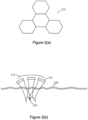
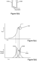
- FIG. 1B depicts a tissue injury 100 caused by the picosecond laser. At least a portion of the cavitation bubble 101 is ablated (e.g., vaporized) and in this pressure bubble 101 the photo thermal effect (e.g., temperature rise) of the picosecond laser on the tissue is largely confined. Biologic tissues and cells proximal to the surface of the cavitation bubble (ablation volume) therefore are exposed to the most intense shock wave region. Regions of tissues and cells farther from the cavitation bubble injury therefore are subject to ever decreasing pressure waves (e.g., ever decreasing magnitude pressure waves).
- the injury 100 is comprised of a central cavitation bubble 101 at least a portion of which has an ablation volume surrounded by tissue regions of relatively high cellular damage 102 having the most damage outside the cavitation bubble 101 with tissue layer 102 having the most cell damage, for example, total damage and immediate cell death, which are in turn surrounded by tissue layers 103, 104 and 105 having progressively lower cellular damage such that longer term cell death occurs with each progressively outer layer.
- layer 104 has a longer term cell damage (e.g., where cell death takes from about 2 to about 7 days) than layer 103 (e.g., where cell death takes from about 1 to about 2 days).
- the exemplary cell death dates are illustrative. Without being bound to any single theory, Applicants believe that it is important in that ongoing deaths of damaged cells which extend at least for several days and possibly for several weeks after the injury, are believed to enhance healing by continuing to deposit dead cell matter including proteins into nearby tissues. This ongoing long term cell death results in a longer duration of new cell genesis stimulated by the ongoing presence of cellular debris.
- the non-thermal effect (e.g., pressure wave and/or shock wave effect) of the cavitation bubbles are distinct from the pure photothermolysis effect resulting from laser irradiation. Photothermolysis does govern the underlying absorption of the applied laser pulse that forms the cavitation bubbles. Nevertheless, the non-thermal effects (e.g., shock waves and/or pressure wave and/or mechanical effects) are believed to create onion-like layers of lesions having varying amounts of cell damage within the target tissues.
- the femtosecond initiated LIOB's are effective at using the LIOB energy to thoroughly ablate the internal bubble volume leaving little to no energy to escape outside the bubble as photomechanical energy (e.g., shockwaves and/or pressure waves). Such precision is paramount in ophthalmology applications to ensure integrity of the eyes.
- the cavitation bubble injury is mediated by shockwaves and by pressure waves, which create the desired injury.
- pulse widths from about 190 picoseconds to about 900 picoseconds, from about 200 picoseconds to about 500 picoseconds, or from about 260 to about 300 picoseconds
- the cavitation bubble expansion and the resulting mechanical damage all contribute to the mechanism of action.
- pulse widths from about 190 picoseconds to about 900 picoseconds, from about 200 picoseconds to about 500 picoseconds, or from about 260 to about 300 picoseconds can be employed to induce micro injuries that are mediated by plasma explosion initiated cavitation bubbles and the resulting shock waves and pressure waves.
- the laser induced plasma absorbs the laser radiation and thus couples the incident energy efficiently into the material.
- the plasma forms the rest of the laser pulse energy is efficiently coupled into either thermal effect in the case of nanosecond pulse widths or in the case of picosecond pulse widths into mechanical forces caused by shockwaves and pressure waves.
- the mechanical forces cause the bulk of the injury as opposed to a temperature rise.
- our application having pulse widths from about 190 picoseconds to about 900 picoseconds, from about 200 picoseconds to about 500 picoseconds, or from about 260 to about 300 picoseconds essentially sacrifices a small region of the tissue that becomes the cavitation bubble containing the vaporized volume as a means to generate mechanical forces including shock waves and pressure waves to disrupt a much larger external volume than the LIOB (vaporized volume) injury alone.
- the femtosecond pulses initiate a more intense multi-photon avalanche mechanism which so efficiently ablates tissue that little to no energy escapes to surrounding tissues as pressure waves.
- Oraevsky et al (IEEE Journal of Selected Topics in Quantum Electronics, Vol. 2, No. 4, December 1996, 801-809 ) describes picosecond pulsewidth LIOB's in high absorbance tissue with a focus toward the "as short as possible" femtosecond pulse widths to confer the most predictable lesion size and reduced collateral damage.
- Oraevsky discloses data which indicate the reduced utility of femtosecond pulses as compared to picosecond pulses for pressure wave generation, although Oraevsky fails to recognize that picosecond pulses are capable of generating maximized pressure waves. Instead Oraevsky focuses on the higher ablation efficiencies achievable with femtosecond pulses due to multi-photon ionization, thereby ignoring the contribution of the pressure wave generation by picosecond pulse widths.
- the picosecond LIOB differs from nanosecond LIOB in several ways. Due to the nanosecond pulse being relatively longer (10 -9 ) than the picosecond pulse (10 -12 ). It takes longer to accumulate energy in an absorptive center of a cavitation bubble with nanosecond as compared to the time it takes using picosecond laser pulse. Therefore nanosecond pulses precipitate lower magnitude pressure waves having a less steep rising edge, which reduces the peak pressure wave stresses imparted to adjacent tissues (e.g., adjacent tissue layers) as compared to the relatively intense peak pressure waves imparted on adjacent tissue layers by a picosecond laser pulse. Thus, picosecond pulses are more efficient at coupling steep rising pressure waves into tissue compared to nanosecond pulses.
- Oraevsky et al teaches that the ionization threshold fluence is relatively independent of pulsewidth for strongly absorbing gel's (target chromophores in our example). Oraevsky says "The laser threshold fluence is largely independent of pulse duration for strongly absorbing gels”. (Oraevsky Section IV. Experimental results). Thus for very high absorption areas a correspondingly longer pulse duration (longer meaning picosecond or short nanosecond opposed to femtosecond) will suffice to initiate LIOB's. Picosecond pulses however, efficiently convert the ablation expansion or LIOB energy into therapeutic shockwaves that attenuate into pressure waves. In contrast nanosecond or femtosecond pulse durations provide energy that creates the cavitation bubble.
- Picosecond pulse durations therefore confer the ability to treat larger volumes of tissues, cells or targets with LIOB injuries, than is possible with femtosecond pulses of equivalent or even greater fluence. This is true because the volume of tissue treated or injured by picosecond duration LIOB's is greater than the volume treated by femtosecond duration LIOB's due to the greater magnitude and greater effective radius of shockwaves and pressure waves possible with picosecond LIOB's. Femtosecond ablation has such a high ablation efficiency and such a steep wavefront that shockwave and pressure wave effects are retarded at these pulse durations. Femtosecond duration LIOB's are ideal for ophthalmologic or other applications where only ablation is desired and where minimal adjacent tissue damage is desired.
- shock waves and pressure waves of varying intensity propagate through the tissue as a result of a picosecond LIOB injury being imparted on the tissue.
- the propagation of these intense waves through biologic tissues manifests as mechanical stress and strain in the tissue cells.
- Susceptibility to mechanical stress and/or cellular damage varies depending on the cellular structure.
- the susceptibility of tissues containing gas or air volumes to pressure waves and/or shock waves is especially pronounced.
- pulmonary tissues are examples of tissues containing gas or air volumes that may be treated in accordance with the methods and devices disclosed herein.
- Control of applied pulse energy and to a lesser extent pulse duration provides control of lesion size.
- Use of an appropriate lens array can provide control of lesion depth. This allows the clinician to create precise injuries in precise locations in the target tissue.
- the fluence may be further intensified and/or focused beneath the tissue surface, for example using a fractional array as described in U.S. Patent No. 6,997,923 which provide focused regions of tissue separated by untreated or less treated tissue or using a CAP array as described in U.S. Patents 7,856,985 , 8,322,348 and 8,317,779 (incorporated by reference herein) which provides for a non-uniform output beam having high and low fluence zones.
- LIOB mediated mechanical waves e.g., shock waves and/or pressure waves
- LIOB mediated shock wave and pressure wave treatments recruit erythrocytes and stimulate tissue growth. Therefore, other potential re-vascularization applications that utilize LIOB to create initial tissue lesions that initiate a healing response include chronic wound care applications such diabetic related edema and other non-acute wound therapies. Typically such wounds can be characterized by poor vascularization which greatly complicates healing. Burn wounds are another potential therapeutic application. Additionally there are a number of liver and circulatory disorders including calcification of vasculature, which are candidates for re-vascularization therapies based on the creation of LIOB channels.
- the pulse width to tune the expansion bubble such that it provides the desired shock wave and/or pressure wave magnitude (more or less), the desired thermal rise (more or less) or the desired combination of shock wave and/or pressure wave and thermal rise.
- Controlling and/or tuning the plasma expansion bubble is accomplished by selection of pulse width used to initiate and drive the plasma bubble expansion.
- Controlling the ablated volume or lesion size is accomplished by selection of a fluence greater (more or less) than the ablation threshold. More specifically, the laser pulse energy in excess of the ablation threshold serves to expand the ablation bubble size. After avalanche breakdown has occurred any remaining laser pulse energy acts to expand the avalanche lesion size. Accordingly, a user's selection of higher relative fluence for a target will necessarily increase the laser energy delivered to the target area/lesion. Applicants believe that plasma expansion bubbles initiated by pulse widths in the femtosecond, picosecond, and nanosecond ranges act on tissue as follows:
- Sections of micro lens arrays could contain one or more lens such as one or more parabolic shaped lenses 215.
- "four lens" parabolic lens clusters 212 are at the tissue surface 230 and are focused on the same deep spot 220 within the tissue, which is useful to minimize fluence through the intervening tissue until co-incident at the "deep spot" target area 220.
- the breakdown threshold for LIOB is only achieved where the irradiation overlaps at spot 220.
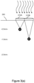
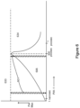
- Figure 3A shows a two single lenses 315A and 315B positioned as a skin surface 330.
- Each of lenses 315A and 315B has a single discrete focus point with 315B achieving a deeper focus depth than lens 315A under otherwise constant treatment conditions.
- the depths from the skin surface 330 that can be achieved with a single lens such as 315A and 315B in skin tissue using a alexandrite laser in the picosecond regime is limited due to scattering within the tissue. For example, the depths of about 0.5 mm and about 1.0 mm can be achieved with single lenses 315A and 315B respectively.
- Relatively shallower targets can be adequately addressed, for example, using single cell micro-lenses, or fewer cell micro-lenses, for example.
- a single tissue area can have relatively shallow targets and relatively deep target and a combination of lenses (e.g., single cell micro-lenses and multi-cell micro-lenses such as quad-cell micro-lenses) can be employed to address the entire depth of the tissue to be treated.
- Use of one or more of the embodiments disclosed in association with Figures 3(a)-3(g) can be employed, for example, to treat scars.
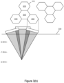
- Figure 3(C) shows a plurality of lens clusters 312 including quad cell (e.g., 4 micro-lens) deep focus micro-lens arrays 315.
- quad cell e.g., 4 micro-lens
- Each 4 micro-lens array targets a relatively deep spot treatment area 320 thereby creating deeper LIOB lesions (e.g., at about 2 mm depth from the tissue surface 330) than would be possible if single cell micro lens arrays (or fewer cell micro lens arrays) were employed.
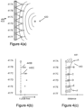
- Figure 3(e) shows a plurality of single cell focus micro-lens arrays 315A and 315B that create two distinct layers of LIOB lesions in a second pass.
- One LIOB lesion layer is shallower than the other (e.g., spot treatment areas 320A are shallower than spot treatment areas 320B). More specifically, treatment areas 320A at a depth of 0.5 mm from the tissue surface 330 and correspond to focus micro-lens array 315A and spot treatment areas 320B are at a depth of 1.0 mm from the tissue surface 330 and correspond to focus micro-lens array 315B.
- Both treatment area lesions are shallower than the layer of LIOB lesions created by the clusters 312 in Figures 3(c) and 3(d) .
- Figure 3(f) depicts the shallowest layer of tissue injury 300A including cavitation bubble 301A and the associated mechanically damaged region 306A of tissue which is at a depth of about 0.5 mm below the tissue surface 330. It also depicts the next deepest layer of tissue injury 300B including cavitation bubble 301B and the associated mechanically damaged region 306B of tissue which is at a depth of about 1.0 mm below the tissue surface 330. And finally it depicts the deepest layer of tissue injury 300 including cavitation bubble 301 and the associated mechanically damaged region 306 of tissue which is at a depth of about 2 mm below the tissue surface 330.
- a picosecond drive pulse 533 is split by an adjustable beam splitter 551 into two equal parts 533A and 533B (e.g., 50% in the first part 533A and 50% in the second part 533B).
- One part e.g., the second part 533B
- the first pulse 533A initiates LIOB (LIOB is not shown in this graphic) and the second pulse 533B arrives at the target while the target area is still ionized by the first pulse 533A, which previously initiated the LIOB.
- a second beam director 553 such as a beam splitter can also be use to further direct light as shown.
- a picosecond laser with an output beam modified via a fractional array e.g., a micro-lens array that creates high intensity focal zones surrounded by non-treated or less treated area of tissue
- a non-uniform beam characterized by a cross-section corresponding to an array of relatively small, relatively high-fluence, spaced-apart regions superimposed on a relatively large, and relatively lower-fluence background provides thermal energy and mechanical energy that cause thermal injury and shockwave and/or pressure wave injury.
- the picosecond laser with the non-uniform array treats tissue there is a component of high fluence causing thermal damage. The regime of injury caused by heat is well known.
- Elastin elongation with minor to no downtime is surprising and desirable in that tissue treatment that leads to desired elastin elongation with less to no downtime opens up the treatment application to the larger population that can't afford downtime and to otherwise open tissue sites where obviousness signs of treatment dissuade treatment of the area.
- elastin elongation is a result of (a) intense thermal action in a small area, (b) mechanical energy (shockwave and pressure wave energy) of the LIOB or (c) a combination of finite thermal intensity and mechanical energy of the LIOB.
- the picopulse laser is at 755 nm and is absorbed in melanin and hemoglobin.
- a purpura like effect was observed upon use of a picopulse laser on tissue. Large voids are not observed in the treated tissue.
- the red blood cells are dispersed throughout the tissue and the temporal dimension of the red blood cells is larger (e.g., at a depth) than that of melanin which is in a local area of the tissue. The dispersal of the red blood cells throughout the tissue could magnify the mechanical part of the effect, which due to the hemoglobin being a target of the 755 nm wavelength, occurs throughout the tissue at the location of the red blood cells in the target.
- EVG stain An Elastin Stain (known as an EVG stain) to study the impact of the picopulse with focused treatment regions of tissue separated by untreated regions of tissue (e.g., a CAPS array) on elastin right after tissue treatment and then later one or more months after tissue treatment, for example, three months after treatment can be performed.
- the EVG stain looks for the live elastin cells. Once elastin cells are thermally denatured they cannot be seen via EVG stain. If elastin fibers are mechanically broken due to the impact of pressure then the EVG stain provides a different result that indicates the mechanical damage to the elastin fibers.
- EVG stain will indicate that elastin fibers (and cell contents) principally damaged by shockwaves will still be visible by means of EVP stain whereas elastin cells damaged by thermal effect will be denatured and thus invisible by means of EVP stain. This effect can distinguish whether thermal or shockwave effects predominantly mediated the tissue injury.
- Controlled re-programming of the scar, of the composition of the scar, specifically its elastic fiber content, is important. It is believed that reforming elastin in the tissue may be controlled by:
- the treatment of tissue using a light source (e.g., laser) in the regime of pulse duration in the picosecond range (without or without CAPs focusing) can elicit a mechanical injury healing process, or a combination mechanical injury and thermal injury healing process and the presence of mechanical injury healing can lead to desirable effects, including:
- the range of photothermal to mechanical effects (with or without CAPs focusing) can be adjusted to optimally treats scars, pigment, skin wrinkles, and skin laxity.
- the pulse width range of about 260-300 picoseconds is believed to make the greatest volume of pressure injury while simultaneously minimizing the deposition of extra-ablation bubble thermal energy. Pressure injury is believed to promote elastic fiber elongation.
- a method of controlling the ratio of mechanical to thermal damage effect can be accomplished by selecting a pulse width for the purpose of controlling the injury including promoting elastic fiber elongation and/or to optimize healing and/or new cell types expressed. Such control can lead to better treatment outcomes.
- a fluence range of from about 0.08J/cm 2 to about 2 J/cm 2 can be employed for highly absorbing targets an up to about 50J/cm 2 (e.g., from about 3 J/cm 2 to about 50 J/cm 2 ) for weakly absorbing targets.
- a light based system e.g., a laser system
- a fractionated beam profile at the unique pulse width of from about 150 picoseconds to about 900 picoseconds, from about 200 picoseconds to about 500 picoseconds, or from about 260 picoseconds to about 300 picoseconds to tissue first imparts a photothermal injury and from that photothermal injury emanate mechanical waves (e.g., shock waves and/or pressure waves) that injure cells and tissues in a manner that stimulates cells and/or causes tissue rejuvenation.
- mechanical waves e.g., shock waves and/or pressure waves
- the injury created by shock waves and/or pressure waves appears to be well suited to tissue rejuvenation.
- the bubble expansion drives a steep edged high pressure wave front that appears to be very useful for causing larger injuries (micro lesions).
- Pressure waves occur below the LIOB threshold near regions of high absorption.
- the high pressure recoiling pressure waves are sufficient to cause injury (micro lesions) to some radius of the absorption center.
- the new and/or repaired cells are expected to include erythrocytes and macrophages that lead to the formation of new collagen and new elastin, for example.
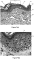
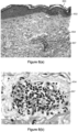
- a PICOSURE ® picosecond laser having a 755 nm wavelength utilizing a lens array having the FOCUS TM trade name with a 6 mm spot size, at a fluence of 0.71 J/cm 2 , and producing a pulse energy of 200 mJ, at a pulse duration of 750 picoseconds was utilized to treat Caucasian skin type II.
- the lens array provides a distance of about 500 ⁇ m between the center of adjacent lenses.
- a skin biopsy punch was taken and its histology was evaluated.
- a standard H&E Stain was utilized to evaluate the biopsied skin.
- Figures 7(a), 7(b) , 8(a) and 8(b) show images of these biopsies.
Landscapes
- Physics & Mathematics (AREA)
- Optics & Photonics (AREA)
- Health & Medical Sciences (AREA)
- Engineering & Computer Science (AREA)
- Surgery (AREA)
- Life Sciences & Earth Sciences (AREA)
- Heart & Thoracic Surgery (AREA)
- Animal Behavior & Ethology (AREA)
- Nuclear Medicine, Radiotherapy & Molecular Imaging (AREA)
- Biomedical Technology (AREA)
- Electromagnetism (AREA)
- Medical Informatics (AREA)
- Molecular Biology (AREA)
- Otolaryngology (AREA)
- General Health & Medical Sciences (AREA)
- Public Health (AREA)
- Veterinary Medicine (AREA)
- Plasma & Fusion (AREA)
- Mechanical Engineering (AREA)
- Laser Surgery Devices (AREA)
- Radiation-Therapy Devices (AREA)
Claims (9)
- Verfahren zur nicht-therapeutischen Gewebebehandlung zur Verbesserung des Erscheinungsbilds von Narbengewebe, wobei das Verfahren aufweist:Bereitstellen eines Pikosekundenlasers, der dazu konfiguriert ist, Licht mit einer Wellenlänge zu emittieren;Bereitstellen eines optischen Systems, das eine Mehrzahl von Brennpunkten aufweist, um eine Laseremission aus dem Pikosekundenlaser auf Ziele in der Epidermis zu konzentrieren;Generieren einer Pikosekunden-Laseremission mit einer Fluenz, aus dem Pikosekundenlaser, wobei die Laseremission eine Wellenlänge hat, die von der Epidermis absorbiert wird; undKonzentrieren der Laseremission durch die Mehrzahl von Brennpunkten auf eine Mehrzahl von Zielen in der Epidermis,wobei jedes Ziel Licht aus der konzentrierten Laseremission an den Zielen absorbiert und eine Elektronenlawinen-Ionisierung an den Zielen auslöst, um eine Druckwellenemission an Gewebe abzugeben, das den Zielen benachbart ist.
- Verfahren zur nicht-therapeutischen Gewebebehandlung zur Entfernung von Pigmentpartikeln aus einer Hautpigmentierung der Epidermis, wobei das Verfahren aufweist:Bereitstellen eines Pikosekundenlasers, der dazu konfiguriert ist, Licht mit einer Wellenlänge zu emittieren;Bereitstellen eines optischen Systems, das eine Mehrzahl von Brennpunkten aufweist, um eine Laseremission aus dem Pikosekundenlaser auf Ziele in der Epidermis zu konzentrieren;Generieren einer Pikosekunden-Laseremission mit einer Fluenz, aus dem Pikosekundenlaser, wobei die Laseremission eine Wellenlänge hat, die von der Epidermis absorbiert wird; undKonzentrieren der Laseremission durch die Mehrzahl von Brennpunkten auf eine Mehrzahl von Zielen in der Epidermis,wobei jedes Ziel Licht aus der konzentrierten Laseremission an den Zielen absorbiert und eine Elektronenlawinen-Ionisierung an den Zielen auslöst, um eine Druckwellenemission an Gewebe abzugeben, das den Zielen benachbart ist.
- Verfahren der Ansprüche 1 oder 2, wobei die Pikosekunden-Laseremission eine Wellenlänge hat, die von Melanin absorbiert wird.
- Verfahren der Ansprüche 1 oder 2, wobei der Pikosekundenlaser einen Impuls innerhalb des Bereichs von ungefähr 260 Pikosekunden bis ungefähr 900 Pikosekunden emittiert.
- Verfahren der Ansprüche 1 oder 2, wobei der Pikosekundenlaser eine Fluenz hat, die von 0,8 J/cm2 bis ungefähr 50 J/cm2 reicht.
- Verfahren nach Anspruch 2, wobei die Hautpigmentierung der Epidermis eine natürlich vorkommende Hautpigmentierung ist.
- Verfahren nach Anspruch 1, wobei das Narbengewebe eines aus einer hypertrophierten Narbe, einer atrophen Narbe, einer Keloid-Narbe, einer Narbe, die von einer Acne-vulgaris-Infektion verursacht wurde, und Striae ist.
- Verfahren der Ansprüche 1 oder 2, wobei die Impulsdauer von ungefähr 260 Pikosekunden bis ungefähr 500 Pikosekunden reicht.
- Verfahren der Ansprüche 1 oder 2, wobei der Laser einen Wellenlängenbereich von 500 nm bis 1100 nm hat.
Priority Applications (1)
| Application Number | Priority Date | Filing Date | Title |
|---|---|---|---|
| EP25182094.0A EP4591925A3 (de) | 2013-03-13 | 2014-03-13 | Gesteuerte photomechanische und photothermische gewebebehandlung im picosekundenbereich |
Applications Claiming Priority (4)
| Application Number | Priority Date | Filing Date | Title |
|---|---|---|---|
| US201361779411P | 2013-03-13 | 2013-03-13 | |
| US201361909563P | 2013-11-27 | 2013-11-27 | |
| PCT/US2014/026335 WO2014160331A1 (en) | 2013-03-13 | 2014-03-13 | Controlled photomechanical and photothermal tissue treatment in the picosecond regime |
| EP14723550.1A EP2969369B1 (de) | 2013-03-13 | 2014-03-13 | Gesteuerte photomechanische und photothermale gewebebehandlung im picosekundenbereich |
Related Parent Applications (1)
| Application Number | Title | Priority Date | Filing Date |
|---|---|---|---|
| EP14723550.1A Division EP2969369B1 (de) | 2013-03-13 | 2014-03-13 | Gesteuerte photomechanische und photothermale gewebebehandlung im picosekundenbereich |
Related Child Applications (1)
| Application Number | Title | Priority Date | Filing Date |
|---|---|---|---|
| EP25182094.0A Division EP4591925A3 (de) | 2013-03-13 | 2014-03-13 | Gesteuerte photomechanische und photothermische gewebebehandlung im picosekundenbereich |
Publications (3)
| Publication Number | Publication Date |
|---|---|
| EP4094876A1 EP4094876A1 (de) | 2022-11-30 |
| EP4094876C0 EP4094876C0 (de) | 2025-07-02 |
| EP4094876B1 true EP4094876B1 (de) | 2025-07-02 |
Family
ID=50693980
Family Applications (3)
| Application Number | Title | Priority Date | Filing Date |
|---|---|---|---|
| EP14723550.1A Active EP2969369B1 (de) | 2013-03-13 | 2014-03-13 | Gesteuerte photomechanische und photothermale gewebebehandlung im picosekundenbereich |
| EP25182094.0A Pending EP4591925A3 (de) | 2013-03-13 | 2014-03-13 | Gesteuerte photomechanische und photothermische gewebebehandlung im picosekundenbereich |
| EP22157332.2A Active EP4094876B1 (de) | 2013-03-13 | 2014-03-13 | Gesteuerte photomechanische und photothermale gewebebehandlung im picosekundenbereich |
Family Applications Before (2)
| Application Number | Title | Priority Date | Filing Date |
|---|---|---|---|
| EP14723550.1A Active EP2969369B1 (de) | 2013-03-13 | 2014-03-13 | Gesteuerte photomechanische und photothermale gewebebehandlung im picosekundenbereich |
| EP25182094.0A Pending EP4591925A3 (de) | 2013-03-13 | 2014-03-13 | Gesteuerte photomechanische und photothermische gewebebehandlung im picosekundenbereich |
Country Status (3)
| Country | Link |
|---|---|
| US (2) | US20150080863A1 (de) |
| EP (3) | EP2969369B1 (de) |
| WO (1) | WO2014160331A1 (de) |
Families Citing this family (12)
| Publication number | Priority date | Publication date | Assignee | Title |
|---|---|---|---|---|
| KR102136901B1 (ko) * | 2012-04-18 | 2020-07-22 | 싸이노슈어, 엘엘씨 | 피코초 레이저 장치 및 그를 사용한 표적 조직의 치료 방법 |
| US20150216598A1 (en) * | 2013-03-13 | 2015-08-06 | Cynosure, Inc. | Controlled photomechanical and photothermal tissue treatment in the picosecond regime |
| WO2014145707A2 (en) | 2013-03-15 | 2014-09-18 | Cynosure, Inc. | Picosecond optical radiation systems and methods of use |
| RU2652746C2 (ru) * | 2013-04-25 | 2018-04-28 | Конинклейке Филипс Н.В. | Неинвазивное устройство для лечения кожи с использованием лазерного света |
| DK3498211T3 (da) * | 2013-08-09 | 2025-03-24 | Massachusetts Gen Hospital | Apparat til behandling af dermal melasma |
| US9913688B1 (en) | 2013-10-01 | 2018-03-13 | Cutera, Inc. | Split pulse picosecond laser for tattoo removal |
| US10245033B2 (en) | 2015-03-06 | 2019-04-02 | Ethicon Llc | Surgical instrument comprising a lockable battery housing |
| WO2018122270A1 (en) * | 2016-12-28 | 2018-07-05 | Koninklijke Philips N.V. | Light based skin treatment device |
| EP3510960A1 (de) | 2018-01-12 | 2019-07-17 | Koninklijke Philips N.V. | Faltenbehandlungssystem und verfahren im zusammenhang mit der faltenbehandlung |
| IL279604B2 (en) * | 2018-06-22 | 2025-09-01 | Avava Inc | Selective tissue treatment device |
| CN112714636B (zh) * | 2018-09-18 | 2022-12-13 | 国神光电科技(上海)有限公司 | 使用一系列脉冲激光的医学治疗系统和方法 |
| FR3143312A1 (fr) | 2022-12-16 | 2024-06-21 | L'oréal | Procédé utilisant la lumière et une composition cosmétique |
Family Cites Families (20)
| Publication number | Priority date | Publication date | Assignee | Title |
|---|---|---|---|---|
| US6156030A (en) * | 1997-06-04 | 2000-12-05 | Y-Beam Technologies, Inc. | Method and apparatus for high precision variable rate material removal and modification |
| US7649153B2 (en) * | 1998-12-11 | 2010-01-19 | International Business Machines Corporation | Method for minimizing sample damage during the ablation of material using a focused ultrashort pulsed laser beam |
| US6808532B2 (en) * | 2000-12-15 | 2004-10-26 | Dan E. Andersen | Laser treatment for reducing wrinkles |
| EP2289598A1 (de) | 2000-12-28 | 2011-03-02 | Palomar Medical Technologies, Inc. | Verfahren und Vorrichtung zur therapeutischen Behandlung der Haut |
| US20050049582A1 (en) * | 2001-12-12 | 2005-03-03 | Debenedictis Leonard C. | Method and apparatus for fractional photo therapy of skin |
| AU2003256252A1 (en) * | 2002-05-31 | 2003-12-19 | Duke University Office Of Science And Technology | Method and apparatus for infrared tissue ablation |
| US20050058701A1 (en) * | 2003-01-29 | 2005-03-17 | Yossi Gross | Active drug delivery in the gastrointestinal tract |
| CN100479778C (zh) * | 2003-08-04 | 2009-04-22 | 皇家飞利浦电子股份有限公司 | 通过激光感应光学击穿作用缩短毛发的装置 |
| US8932278B2 (en) * | 2004-07-12 | 2015-01-13 | Nikolai Tankovich | Skin treatment system with time modulated laser pulses |
| US7856985B2 (en) | 2005-04-22 | 2010-12-28 | Cynosure, Inc. | Method of treatment body tissue using a non-uniform laser beam |
| US20070213695A1 (en) * | 2006-03-08 | 2007-09-13 | Paul Perl | Continuous skin contact handpiece system for cooling during controlled emmission of light and a method thereof |
| US7929579B2 (en) | 2006-08-02 | 2011-04-19 | Cynosure, Inc. | Picosecond laser apparatus and methods for its operation and use |
| US7586957B2 (en) * | 2006-08-02 | 2009-09-08 | Cynosure, Inc | Picosecond laser apparatus and methods for its operation and use |
| US20080055755A1 (en) * | 2006-08-31 | 2008-03-06 | Searete Llc, A Limited Liability Corporation Of The State Of Delaware | Electromagnetic device and method |
| WO2008025371A1 (de) * | 2006-09-01 | 2008-03-06 | Wavelight Aesthetic Gmbh | Vorrichtung für die lichtbehandlung der haut |
| WO2008089344A2 (en) * | 2007-01-19 | 2008-07-24 | Joseph Neev | Devices and methods for generation of subsurface micro-disruptions for biomedical applications |
| EP2307095B1 (de) * | 2008-06-29 | 2020-06-03 | Venus Concept Ltd | Kosmetisches gerät für erhöhte hautverjüngung |
| WO2010102255A1 (en) * | 2009-03-05 | 2010-09-10 | Cynosure, Inc. | Non-uniform beam optical treatment methods and systems |
| DK2747693T3 (en) * | 2011-08-26 | 2018-07-02 | On Light Sciences Inc | SYSTEM AND PROCEDURE FOR TATTOO REMOVAL |
| US9254174B2 (en) * | 2013-02-28 | 2016-02-09 | Fotona D.O.O. | Method for lightening or eradicating pigments in human skin |
-
2014
- 2014-03-13 EP EP14723550.1A patent/EP2969369B1/de active Active
- 2014-03-13 EP EP25182094.0A patent/EP4591925A3/de active Pending
- 2014-03-13 WO PCT/US2014/026335 patent/WO2014160331A1/en not_active Ceased
- 2014-03-13 EP EP22157332.2A patent/EP4094876B1/de active Active
- 2014-03-13 US US14/209,270 patent/US20150080863A1/en not_active Abandoned
-
2022
- 2022-11-01 US US17/978,656 patent/US20230120325A1/en active Pending
Also Published As
| Publication number | Publication date |
|---|---|
| EP2969369A1 (de) | 2016-01-20 |
| US20150080863A1 (en) | 2015-03-19 |
| EP4094876A1 (de) | 2022-11-30 |
| EP4591925A2 (de) | 2025-07-30 |
| EP4094876C0 (de) | 2025-07-02 |
| WO2014160331A9 (en) | 2015-03-19 |
| EP2969369B1 (de) | 2022-03-09 |
| WO2014160331A1 (en) | 2014-10-02 |
| EP4591925A3 (de) | 2025-11-19 |
| US20230120325A1 (en) | 2023-04-20 |
Similar Documents
| Publication | Publication Date | Title |
|---|---|---|
| US20230120325A1 (en) | Systems and Methods of Optically Targeting Melanin and other Tissue Components for Enhanced Dermal Treatment | |
| US11664637B2 (en) | Picosecond laser apparatus and methods for treating target tissues with same | |
| JP6217044B2 (ja) | 皮膚レーザー治療用装置及び方法 | |
| Omi et al. | The role of the CO2 laser and fractional CO2 laser in dermatology | |
| US20160128777A1 (en) | Controlled Photomechanical and Photothermal Treatment of Mucosal Tissue | |
| US20050055071A1 (en) | Method of treating erythematous papules | |
| Orenstein et al. | Treatment of rhinophyma with Er: YAG laser | |
| Clementoni et al. | Facial teleangectasias: our experience in treatment with IPL | |
| Dover et al. | Lasers in skin resurfacing | |
| Hardaway et al. | Non-ablative cutaneous remodeling with a 1.45 µm mid-infrared diode laser: phase I | |
| US20190201096A1 (en) | Controlled photomechanical and photothermal tissue treatment in the picosecond regime | |
| HK40081923B (en) | Controlled photomechanical and photothermal tissue treatment in the picosecond regime | |
| HK40081923A (en) | Controlled photomechanical and photothermal tissue treatment in the picosecond regime | |
| RU2550012C1 (ru) | Способ удаления татуировок | |
| Groff et al. | Fractional carbon dioxide laser and plasmakinetic skin resurfacing | |
| Marini et al. | Fractional Er: YAG skin conditioning for enhanced efficacy for Nd: YAG Q switched laser tattoo removal | |
| Ohshiro | Auto-simultaneous laser treatment: a new effect-based classification | |
| Juhong et al. | Post-laser hair removal folliculitis: A case report. | |
| Ge et al. | Lasers and Light Sources for Vascular and Pigmented Components of Photoaging | |
| Hernandez-Jimenez | Lasers in Cosmetic Dermatology & Skincare Practice | |
| Raminder Saluja et al. | Picosecond Laser Tattoos and Skin Rejuvenation | |
| Almeida et al. | Laser ablation of cutaneous leg veins | |
| Van Swol et al. | Optimization of dosimetry and safety using the holmium laser for urology | |
| Garibyan et al. | Lasers in dermatology | |
| Pandit | LASERS IN HEMANGIOMAS |
Legal Events
| Date | Code | Title | Description |
|---|---|---|---|
| PUAI | Public reference made under article 153(3) epc to a published international application that has entered the european phase |
Free format text: ORIGINAL CODE: 0009012 |
|
| STAA | Information on the status of an ep patent application or granted ep patent |
Free format text: STATUS: THE APPLICATION HAS BEEN PUBLISHED |
|
| AC | Divisional application: reference to earlier application |
Ref document number: 2969369 Country of ref document: EP Kind code of ref document: P |
|
| AK | Designated contracting states |
Kind code of ref document: A1 Designated state(s): AL AT BE BG CH CY CZ DE DK EE ES FI FR GB GR HR HU IE IS IT LI LT LU LV MC MK MT NL NO PL PT RO RS SE SI SK SM TR |
|
| REG | Reference to a national code |
Ref country code: HK Ref legal event code: DE Ref document number: 40081923 Country of ref document: HK |
|
| STAA | Information on the status of an ep patent application or granted ep patent |
Free format text: STATUS: REQUEST FOR EXAMINATION WAS MADE |
|
| 17P | Request for examination filed |
Effective date: 20230530 |
|
| RBV | Designated contracting states (corrected) |
Designated state(s): AL AT BE BG CH CY CZ DE DK EE ES FI FR GB GR HR HU IE IS IT LI LT LU LV MC MK MT NL NO PL PT RO RS SE SI SK SM TR |
|
| GRAP | Despatch of communication of intention to grant a patent |
Free format text: ORIGINAL CODE: EPIDOSNIGR1 |
|
| STAA | Information on the status of an ep patent application or granted ep patent |
Free format text: STATUS: GRANT OF PATENT IS INTENDED |
|
| INTG | Intention to grant announced |
Effective date: 20250214 |
|
| RIN1 | Information on inventor provided before grant (corrected) |
Inventor name: MIRKOV, MIRKO GEORGIEV Inventor name: WELCHES, RICHARD SHAUN |
|
| GRAS | Grant fee paid |
Free format text: ORIGINAL CODE: EPIDOSNIGR3 |
|
| GRAA | (expected) grant |
Free format text: ORIGINAL CODE: 0009210 |
|
| STAA | Information on the status of an ep patent application or granted ep patent |
Free format text: STATUS: THE PATENT HAS BEEN GRANTED |
|
| AC | Divisional application: reference to earlier application |
Ref document number: 2969369 Country of ref document: EP Kind code of ref document: P |
|
| AK | Designated contracting states |
Kind code of ref document: B1 Designated state(s): AL AT BE BG CH CY CZ DE DK EE ES FI FR GB GR HR HU IE IS IT LI LT LU LV MC MK MT NL NO PL PT RO RS SE SI SK SM TR |
|
| REG | Reference to a national code |
Ref country code: GB Ref legal event code: FG4D |
|
| REG | Reference to a national code |
Ref country code: CH Ref legal event code: EP |
|
| REG | Reference to a national code |
Ref country code: DE Ref legal event code: R096 Ref document number: 602014092113 Country of ref document: DE |
|
| REG | Reference to a national code |
Ref country code: IE Ref legal event code: FG4D |
|
| U01 | Request for unitary effect filed |
Effective date: 20250729 |
|
| U07 | Unitary effect registered |
Designated state(s): AT BE BG DE DK EE FI FR IT LT LU LV MT NL PT RO SE SI Effective date: 20250804 |